EP3715606B1 - Method and system for controlling a pneumatic valve - Google Patents
Method and system for controlling a pneumatic valve Download PDFInfo
- Publication number
- EP3715606B1 EP3715606B1 EP20166402.6A EP20166402A EP3715606B1 EP 3715606 B1 EP3715606 B1 EP 3715606B1 EP 20166402 A EP20166402 A EP 20166402A EP 3715606 B1 EP3715606 B1 EP 3715606B1
- Authority
- EP
- European Patent Office
- Prior art keywords
- solenoid
- input signal
- air valve
- starter air
- steady
- Prior art date
- Legal status (The legal status is an assumption and is not a legal conclusion. Google has not performed a legal analysis and makes no representation as to the accuracy of the status listed.)
- Active
Links
Images



Classifications
-
- F—MECHANICAL ENGINEERING; LIGHTING; HEATING; WEAPONS; BLASTING
- F15—FLUID-PRESSURE ACTUATORS; HYDRAULICS OR PNEUMATICS IN GENERAL
- F15B—SYSTEMS ACTING BY MEANS OF FLUIDS IN GENERAL; FLUID-PRESSURE ACTUATORS, e.g. SERVOMOTORS; DETAILS OF FLUID-PRESSURE SYSTEMS, NOT OTHERWISE PROVIDED FOR
- F15B11/00—Servomotor systems without provision for follow-up action; Circuits therefor
- F15B11/02—Systems essentially incorporating special features for controlling the speed or actuating force of an output member
- F15B11/028—Systems essentially incorporating special features for controlling the speed or actuating force of an output member for controlling the actuating force
- F15B11/032—Systems essentially incorporating special features for controlling the speed or actuating force of an output member for controlling the actuating force by means of fluid-pressure converters
-
- F—MECHANICAL ENGINEERING; LIGHTING; HEATING; WEAPONS; BLASTING
- F02—COMBUSTION ENGINES; HOT-GAS OR COMBUSTION-PRODUCT ENGINE PLANTS
- F02C—GAS-TURBINE PLANTS; AIR INTAKES FOR JET-PROPULSION PLANTS; CONTROLLING FUEL SUPPLY IN AIR-BREATHING JET-PROPULSION PLANTS
- F02C7/00—Features, components parts, details or accessories, not provided for in, or of interest apart form groups F02C1/00 - F02C6/00; Air intakes for jet-propulsion plants
- F02C7/26—Starting; Ignition
- F02C7/268—Starting drives for the rotor, acting directly on the rotor of the gas turbine to be started
- F02C7/275—Mechanical drives
- F02C7/277—Mechanical drives the starter being a separate turbine
-
- F—MECHANICAL ENGINEERING; LIGHTING; HEATING; WEAPONS; BLASTING
- F01—MACHINES OR ENGINES IN GENERAL; ENGINE PLANTS IN GENERAL; STEAM ENGINES
- F01D—NON-POSITIVE DISPLACEMENT MACHINES OR ENGINES, e.g. STEAM TURBINES
- F01D17/00—Regulating or controlling by varying flow
- F01D17/20—Devices dealing with sensing elements or final actuators or transmitting means between them, e.g. power-assisted
- F01D17/205—Centrifugal governers directly linked to valves
-
- F—MECHANICAL ENGINEERING; LIGHTING; HEATING; WEAPONS; BLASTING
- F01—MACHINES OR ENGINES IN GENERAL; ENGINE PLANTS IN GENERAL; STEAM ENGINES
- F01D—NON-POSITIVE DISPLACEMENT MACHINES OR ENGINES, e.g. STEAM TURBINES
- F01D19/00—Starting of machines or engines; Regulating, controlling, or safety means in connection therewith
-
- F—MECHANICAL ENGINEERING; LIGHTING; HEATING; WEAPONS; BLASTING
- F02—COMBUSTION ENGINES; HOT-GAS OR COMBUSTION-PRODUCT ENGINE PLANTS
- F02D—CONTROLLING COMBUSTION ENGINES
- F02D41/00—Electrical control of supply of combustible mixture or its constituents
- F02D41/20—Output circuits, e.g. for controlling currents in command coils
-
- F—MECHANICAL ENGINEERING; LIGHTING; HEATING; WEAPONS; BLASTING
- F02—COMBUSTION ENGINES; HOT-GAS OR COMBUSTION-PRODUCT ENGINE PLANTS
- F02M—SUPPLYING COMBUSTION ENGINES IN GENERAL WITH COMBUSTIBLE MIXTURES OR CONSTITUENTS THEREOF
- F02M67/00—Apparatus in which fuel-injection is effected by means of high-pressure gas, the gas carrying the fuel into working cylinders of the engine, e.g. air-injection type
- F02M67/10—Injectors peculiar thereto, e.g. valve less type
- F02M67/12—Injectors peculiar thereto, e.g. valve less type having valves
-
- F—MECHANICAL ENGINEERING; LIGHTING; HEATING; WEAPONS; BLASTING
- F02—COMBUSTION ENGINES; HOT-GAS OR COMBUSTION-PRODUCT ENGINE PLANTS
- F02D—CONTROLLING COMBUSTION ENGINES
- F02D41/00—Electrical control of supply of combustible mixture or its constituents
- F02D41/20—Output circuits, e.g. for controlling currents in command coils
- F02D2041/202—Output circuits, e.g. for controlling currents in command coils characterised by the control of the circuit
- F02D2041/2024—Output circuits, e.g. for controlling currents in command coils characterised by the control of the circuit the control switching a load after time-on and time-off pulses
- F02D2041/2027—Control of the current by pulse width modulation or duty cycle control
-
- F—MECHANICAL ENGINEERING; LIGHTING; HEATING; WEAPONS; BLASTING
- F02—COMBUSTION ENGINES; HOT-GAS OR COMBUSTION-PRODUCT ENGINE PLANTS
- F02D—CONTROLLING COMBUSTION ENGINES
- F02D41/00—Electrical control of supply of combustible mixture or its constituents
- F02D41/20—Output circuits, e.g. for controlling currents in command coils
- F02D2041/202—Output circuits, e.g. for controlling currents in command coils characterised by the control of the circuit
- F02D2041/2051—Output circuits, e.g. for controlling currents in command coils characterised by the control of the circuit using voltage control
-
- F—MECHANICAL ENGINEERING; LIGHTING; HEATING; WEAPONS; BLASTING
- F15—FLUID-PRESSURE ACTUATORS; HYDRAULICS OR PNEUMATICS IN GENERAL
- F15B—SYSTEMS ACTING BY MEANS OF FLUIDS IN GENERAL; FLUID-PRESSURE ACTUATORS, e.g. SERVOMOTORS; DETAILS OF FLUID-PRESSURE SYSTEMS, NOT OTHERWISE PROVIDED FOR
- F15B2211/00—Circuits for servomotor systems
- F15B2211/80—Other types of control related to particular problems or conditions
- F15B2211/885—Control specific to the type of fluid, e.g. specific to magnetorheological fluid
- F15B2211/8855—Compressible fluids, e.g. specific to pneumatics
Definitions
- the present disclosure relates generally to pneumatic valves, and more particularly to control of pneumatic starter air valves of gas turbine engines.
- Gas turbine aircraft engines may be configured for air/pneumatic starts with the use of an air flow provided from an air source, such as from an auxiliary power unit, an external air compressor or cross-bleed air from an already running engine.
- An engine's compressor spools are rotated by the air flow acting directly on the compressor blades to start the engine or the air flow drives a separate motor that starts the engine.
- a pneumatic starter air valve can control the air flow supplied to the compressor spools or the separate motor for starting the engine.
- a solenoid of the pneumatic starter air valve can be actuated with a direct current voltage signal to provide the air flow for turning the engine. However, it is harder to control the pneumatic starter air valve response when the solenoid is actuated with a non-direct current voltage signal.
- US 2018/346100 discloses a prior art manual bowed rotor and full override.
- a method for controlling a pneumatic starter air valve of a gas turbine engine comprises controlling the starter air valve in a first mode of operation by actuating a first solenoid of the starter air valve with a steady-state input signal, allowing passage of the steady-state input signal to a second solenoid of the starter air valve to actuate the second solenoid and enable pressure regulation of the starter air valve, controlling the starter air valve in a second mode of operation by actuating the first solenoid with a pulse-width modulation input signal, and preventing passage of the pulse-width modulation input signal to the second solenoid to disable the pressure regulation in the second mode of operation.
- the pulse-width modulation input signal has a rate and a duty cycle to cause the starter air valve to provide pressure lower than a regulating point of the starter air valve used for starting the engine.
- allowing passage of the steady-state input signal to the second solenoid comprises time delaying the steady-state input signal by a period of time larger than a pulse width time period of the pulse-width modulation input signal.
- allowing passage of the steady-state input signal to the second solenoid comprises: comparing a voltage level of the steady-state input signal to a threshold; and allowing passage of the steady-state input signal to the second solenoid when the threshold has been exceed for a period of time.
- preventing passage of the pulse-width modulation input signal to the second solenoid comprises: comparing a voltage level of the pulse-width modulation input signal to a threshold; and preventing passage of the pulse-width modulation input signal to the second solenoid while the threshold has been exceed for less than a period of time.
- a reference pressure of the starter air valve is vented to ambient pressure when pressure regulation is disabled.
- controlling the starter air valve in the first mode of operation comprises controlling the starter air valve in the first mode of operation in response to a request for starting the engine and controlling the starter air valve in the second mode of operation comprises controlling the starter air valve in the second mode of operation in response to a request for mitigating bowing of a rotor of the engine.
- a system for controlling a pneumatic starter air valve of a gas turbine engine comprising a first solenoid configured to operate the starter air valve in a first mode when the first solenoid is actuated by a steady-state input signal and to operate the starter air valve in a second mode when the first solenoid is actuated by a pulse-width modulation input signal, a second solenoid configured to enable pressure regulation by a pressure regulator of the starter air valve when the second solenoid is actuated by the steady-state voltage input signal, and an electronic circuit between the first solenoid and the second solenoid, the electronic circuit configured to allow passage of the steady-state input signal to the second solenoid and to prevent passage of the pulse-width modulation input signal to the second solenoid, the pressure regulation being disabled when the second solenoid is prevented from being actuated.
- the pulse-width modulation input signal has a rate and a duty cycle to cause the starter air valve to provide pressure lower than a regulating point of the starter air valve used for starting the engine.
- the electronic circuit comprises:
- control component is a relay.
- control component is a transistor.
- the system comprises a pressure regulator and the pressure regulator vents a reference pressure of the valve to ambient pressure when pressure regulation by the pressure regulator is disabled.
- FIG 1 illustrates a gas turbine engine 10 that may be started using the methods and systems described herein.
- Engine 10 generally comprises in serial flow communication: a fan rotor 12 through which ambient air is propelled, a compressor section 14 for pressurizing the air, a combustor 16 in which the compressed air is mixed with fuel and ignited for generating an annular stream of hot combustion gases, and a turbine section 18 for extracting energy from the combustion gases.
- the fan rotor 12 comprises a plurality of fan blades 20. It should be understood that while the engine 10 is a turbofan engine, the methods and systems described herein may be applicable to any other type of gas turbine engine, such as a turboprop, turboshaft or any other suitable industrial engine that may be air started.
- a controllable power supply 203 is configured to output a steady-state voltage signal (i.e., a direct current (DC) voltage signal) or a pulse-width modulation (PWM) voltage signal, which is provided to an input 216 of the system 200.
- the steady-state voltage signal provided to the input 216 is referred to herein as the "steady-state input signal” and the PWM voltage signal provided to the input 216 is referred to herein as the "PWM input signal”.
- the controllable power supply 203 can be controlled, for example, by an engine controller or an aircraft computer, to provide the steady-state input signal or the PWM input signal.
- a first solenoid 201 of the pneumatic valve 210 is configured to operate the pneumatic valve 210 in a first mode of operation when the first solenoid 201 is actuated by the steady-state input signal.
- the first solenoid 201 is configured to operate the pneumatic valve 210 in a second mode of operation when the first solenoid 201 is actuated by the PWM input signal.
- a second solenoid 202 of the pneumatic valve 210 is configured to enable pressure regulation by a mechanical pressure regulator 222 of the pneumatic valve 210 when the second solenoid 202 is actuated by the steady-state input signal. When the second solenoid 202 is not actuated, pressure regulation by the pressure regulator 222 is disabled. While the second solenoid 202 is illustrated as part of the pneumatic valve 210, it should be understood that this is for illustrative purposes only and that the second solenoid 202 may, in some embodiments, be separate from the pneumatic valve 210.
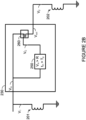
- An electronic circuit 230 is positioned between the first solenoid 201 and the second solenoid 202.
- the electronic circuit 230 is configured to prevent the second solenoid 202 from being actuated by the PWM input signal, when the pneumatic valve 210 is operating in the second mode.
- the electronic circuit 230 is configured to allow passage of the steady-state input signal to the second solenoid 202, when the pneumatic valve 210 is operating in the first mode. While the electronic circuit 230 is illustrated as separate from the pneumatic valve 210, it should be understood that this is for illustrative purposes only and that the electronic circuit 230 may, in some embodiments, be integrated with the pneumatic valve 210.
- the first mode of operation is used for starting the engine 10, in accordance with some embodiments.
- both the first solenoid 201 and the second solenoid 202 are actuated with the steady-state input signal.
- the first solenoid 201 is configured to cause a valve mechanism 220 to open.
- the second solenoid 202 is configured to enable the pressure regulator 222 to regulate air pressure downstream of the valve mechanism 220.
- an air flow is provided to an inlet 212 of the pneumatic valve 210 via a connected air source, such as from an auxiliary power unit, an external air compressor or cross-bleed air from an already running engine.
- a connected air source such as from an auxiliary power unit, an external air compressor or cross-bleed air from an already running engine.
- the valve mechanism 220 is open and the air flow is regulated by the pressure regulator 222, the regulated air flow is provided via an outlet 214 of the pneumatic valve 210 for starting the engine 10.
- the pressure regulator 222 is enabled, the pressure regulator is configured to regulate pressure at a mechanical regulating point suitable for starting the engine 10.
- the second mode of operation is used for low speed motoring functions of the engine 10, in accordance with some embodiments.
- this may cause the engine 10 to rotate at a specific speed depending on a rate and a duty cycle of the PWM input signal.
- the upper portion of the engine 10 may cool more slowly than the bottom portion of the engine 10, which may result in the bending of components of the engine 10.
- the bending of the engine's rotor may be referred to as "rotor bow”. It is not desirable to start the engine 10 when there is "rotor bow”, as this can lead to damage to the engine 10. Accordingly, it may be desirable to operate in the second mode of operation to mitigate rotor bow.
- the PWM input signal has a rate and a duty cycle to cause the pneumatic valve 210 to provide pressure lower than the regulating point of the pneumatic valve 210. This is because the PWM input signal would cause the valve mechanism 220 to pulse open and close and the pressure regulation by the pressure regulator 222 would be disabled. Accordingly, the second mode of operation may be used to mitigate bowing of the rotor by causing the pneumatic valve 210 to provide pressure lower than the regulating point which would normally be used for starting the engine 10. In some embodiments, when the second solenoid 202 is not actuated (i.e., when pressure regulation by the pressure regulator 222 is disabled), the pressure regulator 220 vents a reference pressure of the pneumatic valve 210 to ambient pressure.
- the electronic circuit 230 comprises a power supply monitor circuit 250 and a control component 260.
- the electronic circuit 230 may comprise other electrical and/or electronic components (e.g., resistors, capacitors, diodes, transistors, etc.) to configure the arrangement of the power supply monitor circuit 250 and the control component 260, as would be understood by the person skilled in the art.
- the power supply monitor circuit 250 is configured to enable the control component 260 to allow passage of the input voltage signal V in provided to the electronic circuit 230, when a voltage level of the input voltage signal V in exceeds a threshold R for a period of time T p .
- the power supply monitor circuit 250 is configured to disable the control component 260 to prevent passage of the input voltage signal V in , when the voltage level of the input voltage signal V in does not exceed the threshold R for the period of time T p .
- the power supply monitor circuit 250 is configured to monitor the input voltage signal V in and to compare the voltage level of the input voltage signal V in to the threshold R.
- a timer is started.
- the power supply monitor circuit 250 outputs a control signal V C having a positive voltage.
- the timer is reset and the power supply monitor circuit 250 outputs a zero voltage signal for the control signal V C .
- the power supply monitor circuit 250 may be implemented using any suitable power supply monitor circuit.
- the power supply monitor circuit 250 is the LTC9200 programmable quad supply monitor with adjustable reset timer provided by Linear Technology TM .
- the control component 260 controls the passage of the input voltage signal V in to the output of the electronic circuit 230, as output voltage V out .
- the control component 260 receives the positive voltage control signal V c
- the control component 260 allows for the input voltage signal V in to be output from the electronic circuit 230, as output voltage V out .
- the control component 260 receives the zero voltage control signal V c
- the control component 260 prevents the input voltage signal V in from being output from the electronic circuit 230, as output voltage V out .
- control component 260 is a transistor, which when the positive voltage control signal V c is applied at the transistor's gate (or base), the input voltage signal V in at the source (or collector) is provided to the drain (or emitter), as output voltage V out .
- control component 260 may be a relay (or a switch), which when the positive voltage control signal V c is received by the relay, the relay is closed and the input voltage signal V in passes through the relay, as output voltage V out .
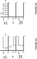
- a signal diagram illustrates the input voltage signal V in , the output voltage V out , and the voltage control signal V c for when the pneumatic valve 210 is operated in the first mode of operation, in accordance with some embodiments.
- the input voltage signal V in is a steady-state input signal, which is also provided to the first solenoid 201 (shown in Figure 2B as V 1 ).
- the control signal V c is a positive voltage and the output voltage V out is a steady-state voltage signal, which is provided to the second solenoid 202 (shown in Figure 2B as V 2 ).
- the electronic circuit 230 causes in some embodiments for there to be a time delay (corresponding to the time period T p ) of the steady-state input signal which is used to actuate the second solenoid 202.
- the electronic circuit 230 is a time delay circuit configured to time delay a steady-state input signal and prevent passage of a PWM input signal.
- a signal diagram illustrates the input voltage signal V in , the output voltage V out , and the voltage control signal V c for when the pneumatic valve 210 is operated in the second mode of operation, in accordance with some embodiments.
- the input voltage signal V in is a PWM input signal, which is also provided to the first solenoid 201.
- the control signal V c is a zero voltage signal and the output voltage V out is a zero voltage signal, which is provided to the second solenoid 202.
- the electronic circuit 230 may vary depending on practical implementations and the electronic circuit 230 illustrated in Figure 2B is a specific and non-limiting example of implementation of an electronic circuit configured to allow passage of a steady-state input signal and prevent passage of a PWM input signal.
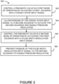
- the pneumatic valve 210 is controlled in a first mode of operation by actuating the first solenoid 201 with a steady-state input signal.
- the pneumatic valve 210 is controlled in a second mode of operation by actuating the first solenoid 201 with a PWM input signal.
- passage of the PWM input signal to the second solenoid 202 is prevented, to disable the pressure regulation in the second mode of operation.
- step 304 comprises time delaying the steady-state input signal provided to the second solenoid 202 by a period of time T p larger than a pulse width time period T w of the PWM input signal.
- step 304 comprises comparing a voltage level of the steady-state input signal to a threshold R and allowing passage of the steady-state input signal to the second solenoid 202 when the threshold R has been exceed for the period of time T p .
- step 308 comprises comparing a voltage level of the PWM input signal to the threshold R and preventing passage of the PWM input signal to the second solenoid 202 while the threshold R has been exceed for less than the period of time T P (i.e., when the threshold R has not been exceeded for the period of time T p ).
- controlling the pneumatic valve 210 in the first mode of operation comprises controlling the pneumatic valve 210 in the first mode of operation in response to a request for starting the engine 10 and controlling the pneumatic valve 210 in the second mode of operation comprises controlling the pneumatic valve 210 in the second mode of operation in response to a request for mitigating bowing of a rotor of the engine 10.
- the PWM input signal has a rate and a duty cycle to cause the pneumatic valve 210 to provide pressure lower than a regulating point of the pneumatic valve 210 used for starting the engine 10.
- a reference pressure of the pneumatic valve is vented to ambient pressure when pressure regulation is disabled.
- the methods and systems may be used to control any other suitable valve and/or any suitable device for any suitable purpose, including, but not limited to, any other suitable pneumatic valve, any suitable solenoid driven device comprising two solenoids and/or any two suitable devices each comprising a solenoid.
- the computing device 400 may be used to control the controllable power supply 203.
- the power supply monitor circuit 250 may be implemented using a computing device of the type of the computing device 400.
- the computing device 400 comprises a processing unit 412 and a memory 414 which has stored therein computer-executable instructions 416.
- the processing unit 412 may comprise any suitable devices configured to implement at least in part the method 300 such that instructions 416, when executed by the computing device 400 or other programmable apparatus, may cause at least in part the functions/acts/steps performed as part of the method 300 as described herein to be executed.
- the processing unit 412 may comprise, for example, any type of general-purpose microprocessor or microcontroller, a digital signal processing (DSP) processor, a central processing unit (CPU), an integrated circuit, a field programmable gate array (FPGA), a reconfigurable processor, other suitably programmed or programmable logic circuits, or any combination thereof.
- DSP digital signal processing
- CPU central processing unit
- FPGA field programmable gate array
- reconfigurable processor other suitably programmed or programmable logic circuits, or any combination thereof.
- the memory 414 may comprise any suitable known or other machine-readable storage medium.
- the memory 414 may comprise non-transitory computer readable storage medium, for example, but not limited to, an electronic, magnetic, optical, electromagnetic, infrared, or semiconductor system, apparatus, or device, or any suitable combination of the foregoing.
- the memory 414 may include a suitable combination of any type of computer memory that is located either internally or externally to device, for example random-access memory (RAM), read-only memory (ROM), compact disc read-only memory (CDROM), electro-optical memory, magneto-optical memory, erasable programmable read-only memory (EPROM), and electrically-erasable programmable read-only memory (EEPROM), Ferroelectric RAM (FRAM) or the like.
- RAM random-access memory
- ROM read-only memory
- CDROM compact disc read-only memory
- electro-optical memory magneto-optical memory
- EPROM erasable programmable read-only memory
- EEPROM electrically-erasable
- Memory 414 may comprise any storage means (e.g., devices) suitable for retrievably storing machine-readable instructions 416 executable by processing unit 412.
- the computing device 400 can be implemented as part of a full-authority digital engine control (FADEC) or other similar device, including electronic engine control (EEC), engine control unit (ECU), and the like.
- FADEC full-authority digital engine control
- EEC electronic engine control
- ECU engine control unit
- Computer-executable instructions 416 may be in many forms, including program modules, executed by one or more computers or other devices.
- program modules include routines, programs, objects, components, data structures, etc., that perform particular tasks or implement particular abstract data types.
- functionality of the program modules may be combined or distributed as desired in various embodiments.
Landscapes
- Engineering & Computer Science (AREA)
- Mechanical Engineering (AREA)
- General Engineering & Computer Science (AREA)
- Chemical & Material Sciences (AREA)
- Combustion & Propulsion (AREA)
- Physics & Mathematics (AREA)
- Fluid Mechanics (AREA)
- Magnetically Actuated Valves (AREA)
- Control Of Turbines (AREA)
Description
- The present disclosure relates generally to pneumatic valves, and more particularly to control of pneumatic starter air valves of gas turbine engines.
- Gas turbine aircraft engines may be configured for air/pneumatic starts with the use of an air flow provided from an air source, such as from an auxiliary power unit, an external air compressor or cross-bleed air from an already running engine. An engine's compressor spools are rotated by the air flow acting directly on the compressor blades to start the engine or the air flow drives a separate motor that starts the engine.
- A pneumatic starter air valve can control the air flow supplied to the compressor spools or the separate motor for starting the engine. A solenoid of the pneumatic starter air valve can be actuated with a direct current voltage signal to provide the air flow for turning the engine. However, it is harder to control the pneumatic starter air valve response when the solenoid is actuated with a non-direct current voltage signal.
- As such, there is a need for improvement.
-
US 2018/346100 discloses a prior art manual bowed rotor and full override. - In one aspect according to the invention, there is provided a method for controlling a pneumatic starter air valve of a gas turbine engine. The method comprises controlling the starter air valve in a first mode of operation by actuating a first solenoid of the starter air valve with a steady-state input signal, allowing passage of the steady-state input signal to a second solenoid of the starter air valve to actuate the second solenoid and enable pressure regulation of the starter air valve, controlling the starter air valve in a second mode of operation by actuating the first solenoid with a pulse-width modulation input signal, and preventing passage of the pulse-width modulation input signal to the second solenoid to disable the pressure regulation in the second mode of operation.
- In a preferred embodiment, the pulse-width modulation input signal has a rate and a duty cycle to cause the starter air valve to provide pressure lower than a regulating point of the starter air valve used for starting the engine.
- In preferred embodiment according to any of the previous embodiments, allowing passage of the steady-state input signal to the second solenoid comprises time delaying the steady-state input signal by a period of time larger than a pulse width time period of the pulse-width modulation input signal.
- In preferred embodiment according to any of the previous embodiments, allowing passage of the steady-state input signal to the second solenoid comprises: comparing a voltage level of the steady-state input signal to a threshold; and allowing passage of the steady-state input signal to the second solenoid when the threshold has been exceed for a period of time.
- In a preferred embodiment according to any of the previous embodiments, preventing passage of the pulse-width modulation input signal to the second solenoid comprises: comparing a voltage level of the pulse-width modulation input signal to a threshold; and preventing passage of the pulse-width modulation input signal to the second solenoid while the threshold has been exceed for less than a period of time.
- In a preferred embodiment according to any of the previous embodiments, a reference pressure of the starter air valve is vented to ambient pressure when pressure regulation is disabled. a preferred embodiment according to any of the previous embodiments, controlling the starter air valve in the first mode of operation comprises controlling the starter air valve in the first mode of operation in response to a request for starting the engine and controlling the starter air valve in the second mode of operation comprises controlling the starter air valve in the second mode of operation in response to a request for mitigating bowing of a rotor of the engine.
- In another aspect according to the invention, there is provided a system for controlling a pneumatic starter air valve of a gas turbine engine. The system comprises a first solenoid configured to operate the starter air valve in a first mode when the first solenoid is actuated by a steady-state input signal and to operate the starter air valve in a second mode when the first solenoid is actuated by a pulse-width modulation input signal, a second solenoid configured to enable pressure regulation by a pressure regulator of the starter air valve when the second solenoid is actuated by the steady-state voltage input signal, and an electronic circuit between the first solenoid and the second solenoid, the electronic circuit configured to allow passage of the steady-state input signal to the second solenoid and to prevent passage of the pulse-width modulation input signal to the second solenoid, the pressure regulation being disabled when the second solenoid is prevented from being actuated.
- In preferred embodiment, the pulse-width modulation input signal has a rate and a duty cycle to cause the starter air valve to provide pressure lower than a regulating point of the starter air valve used for starting the engine.
- In preferred embodiment according to any of the previous embodiments, the electronic circuit comprises:
- a control component configured to allow or prevent passage of an input voltage signal of the electronic circuit to the second solenoid, the input voltage signal being the steady-state input signal or the pulse-width modulation input signal; and
- a power supply monitor circuit configured to compare a voltage level of the input voltage signal to a threshold, the power supply monitor circuit configured to enable the control component to allow passage of the input voltage when the threshold is exceeded from a period of time, and the power supply monitor circuit configured to disable the control component to prevent passage of the input voltage signal when the threshold is not exceeded from the period of time.
- In a preferred embodiment according to any of the previous embodiments, the control component is a relay.
- In a preferred embodiment according to any of the previous embodiments, the control component is a transistor.
- In a preferred embodiment according to any of the previous embodiments, the system comprises a pressure regulator and the pressure regulator vents a reference pressure of the valve to ambient pressure when pressure regulation by the pressure regulator is disabled.
- Reference is now made to the accompanying figures in which:
-
Figure 1 is a schematic of an example gas turbine engine, in accordance with some embodiments; -
Figure 2A is a schematic diagram illustrating a system for controlling a pneumatic valve, in accordance with some embodiments; -
Figure 2B is a schematic diagram illustrating an electronic circuit, in accordance with some embodiments; -
Figure 2C is a signal diagram illustrating voltage signals in a first mode of operation, in accordance with some embodiments; -
Figure 2D is a signal diagram illustrating voltage signals in a second mode of operation, in accordance with some embodiments; -
Figure 3 is a flowchart of a method for controlling a pneumatic valve, in accordance with some embodiments; -
Figure 4 is a block diagram of an example computing device, in accordance with some embodiments. - It will be noted that throughout the appended drawings, like features are identified by like reference numerals.
-
Figure 1 illustrates agas turbine engine 10 that may be started using the methods and systems described herein.Engine 10 generally comprises in serial flow communication: afan rotor 12 through which ambient air is propelled, acompressor section 14 for pressurizing the air, acombustor 16 in which the compressed air is mixed with fuel and ignited for generating an annular stream of hot combustion gases, and aturbine section 18 for extracting energy from the combustion gases. Thefan rotor 12 comprises a plurality offan blades 20. It should be understood that while theengine 10 is a turbofan engine, the methods and systems described herein may be applicable to any other type of gas turbine engine, such as a turboprop, turboshaft or any other suitable industrial engine that may be air started. - With reference to
Figure 2A , there is illustrated asystem 200 for controlling a pneumaticstarter air valve 210 used in air starting an engine, such asengine 10, in accordance with an embodiment. In the illustrated embodiment, acontrollable power supply 203 is configured to output a steady-state voltage signal (i.e., a direct current (DC) voltage signal) or a pulse-width modulation (PWM) voltage signal, which is provided to aninput 216 of thesystem 200. The steady-state voltage signal provided to theinput 216 is referred to herein as the "steady-state input signal" and the PWM voltage signal provided to theinput 216 is referred to herein as the "PWM input signal". Thecontrollable power supply 203 can be controlled, for example, by an engine controller or an aircraft computer, to provide the steady-state input signal or the PWM input signal. - A
first solenoid 201 of thepneumatic valve 210 is configured to operate thepneumatic valve 210 in a first mode of operation when thefirst solenoid 201 is actuated by the steady-state input signal. Thefirst solenoid 201 is configured to operate thepneumatic valve 210 in a second mode of operation when thefirst solenoid 201 is actuated by the PWM input signal. - A
second solenoid 202 of thepneumatic valve 210 is configured to enable pressure regulation by amechanical pressure regulator 222 of thepneumatic valve 210 when thesecond solenoid 202 is actuated by the steady-state input signal. When thesecond solenoid 202 is not actuated, pressure regulation by thepressure regulator 222 is disabled. While thesecond solenoid 202 is illustrated as part of thepneumatic valve 210, it should be understood that this is for illustrative purposes only and that thesecond solenoid 202 may, in some embodiments, be separate from thepneumatic valve 210. - An
electronic circuit 230 is positioned between thefirst solenoid 201 and thesecond solenoid 202. Theelectronic circuit 230 is configured to prevent thesecond solenoid 202 from being actuated by the PWM input signal, when thepneumatic valve 210 is operating in the second mode. Theelectronic circuit 230 is configured to allow passage of the steady-state input signal to thesecond solenoid 202, when thepneumatic valve 210 is operating in the first mode. While theelectronic circuit 230 is illustrated as separate from thepneumatic valve 210, it should be understood that this is for illustrative purposes only and that theelectronic circuit 230 may, in some embodiments, be integrated with thepneumatic valve 210. - The first mode of operation is used for starting the
engine 10, in accordance with some embodiments. In the first mode of operation, both thefirst solenoid 201 and thesecond solenoid 202 are actuated with the steady-state input signal. When thefirst solenoid 201 is actuated with the steady-state input signal, thefirst solenoid 201 is configured to cause avalve mechanism 220 to open. When thesecond solenoid 202 is actuated with the steady-state input signal, thesecond solenoid 202 is configured to enable thepressure regulator 222 to regulate air pressure downstream of thevalve mechanism 220. That is, an air flow is provided to aninlet 212 of thepneumatic valve 210 via a connected air source, such as from an auxiliary power unit, an external air compressor or cross-bleed air from an already running engine. When thevalve mechanism 220 is open and the air flow is regulated by thepressure regulator 222, the regulated air flow is provided via anoutlet 214 of thepneumatic valve 210 for starting theengine 10. When thepressure regulator 222 is enabled, the pressure regulator is configured to regulate pressure at a mechanical regulating point suitable for starting theengine 10. - The second mode of operation is used for low speed motoring functions of the
engine 10, in accordance with some embodiments. By actuating thefirst solenoid 201 with the PWM input signal this may cause theengine 10 to rotate at a specific speed depending on a rate and a duty cycle of the PWM input signal. For example, after theengine 10 has been running and is turned-off, the upper portion of theengine 10 may cool more slowly than the bottom portion of theengine 10, which may result in the bending of components of theengine 10. The bending of the engine's rotor may be referred to as "rotor bow". It is not desirable to start theengine 10 when there is "rotor bow", as this can lead to damage to theengine 10. Accordingly, it may be desirable to operate in the second mode of operation to mitigate rotor bow. In some embodiments, the PWM input signal has a rate and a duty cycle to cause thepneumatic valve 210 to provide pressure lower than the regulating point of thepneumatic valve 210. This is because the PWM input signal would cause thevalve mechanism 220 to pulse open and close and the pressure regulation by thepressure regulator 222 would be disabled. Accordingly, the second mode of operation may be used to mitigate bowing of the rotor by causing thepneumatic valve 210 to provide pressure lower than the regulating point which would normally be used for starting theengine 10. In some embodiments, when thesecond solenoid 202 is not actuated (i.e., when pressure regulation by thepressure regulator 222 is disabled), thepressure regulator 220 vents a reference pressure of thepneumatic valve 210 to ambient pressure. - It should be appreciated that when the
second solenoid 202 is not actuated and the pressure regulation by thepressure regulator 222 is disabled, that this may improve control of the pneumatic valve response while thefirst solenoid 201 is actuated by the PWM input signal. It should further be appreciated that by using theelectronic circuit 230 positioned between the first andsecond solenoids pressure regulator 222 may be done without any additional control signals. - With reference to
Figure 2B , there is illustrated theelectronic circuit 230, in accordance with some embodiments. In the illustrated embodiment, theelectronic circuit 230 comprises a powersupply monitor circuit 250 and acontrol component 260. Theelectronic circuit 230 may comprise other electrical and/or electronic components (e.g., resistors, capacitors, diodes, transistors, etc.) to configure the arrangement of the powersupply monitor circuit 250 and thecontrol component 260, as would be understood by the person skilled in the art. The powersupply monitor circuit 250 is configured to enable thecontrol component 260 to allow passage of the input voltage signal Vin provided to theelectronic circuit 230, when a voltage level of the input voltage signal Vin exceeds a threshold R for a period of time Tp. The powersupply monitor circuit 250 is configured to disable thecontrol component 260 to prevent passage of the input voltage signal Vin, when the voltage level of the input voltage signal Vin does not exceed the threshold R for the period of time Tp. - In accordance with some embodiments, the power
supply monitor circuit 250 is configured to monitor the input voltage signal Vin and to compare the voltage level of the input voltage signal Vin to the threshold R. When the voltage level of the input voltage signal Vin exceeds the threshold R, a timer is started. When the time tm of the timer exceeds a set time period Tp, the powersupply monitor circuit 250 outputs a control signal VC having a positive voltage. When the voltage level of the input voltage signal Vin drops below the threshold, the timer is reset and the powersupply monitor circuit 250 outputs a zero voltage signal for the control signal VC. The powersupply monitor circuit 250 may be implemented using any suitable power supply monitor circuit. In specific and non-limiting examples of implementation, the powersupply monitor circuit 250 is the LTC9200 programmable quad supply monitor with adjustable reset timer provided by Linear Technology™. - The
control component 260 controls the passage of the input voltage signal Vin to the output of theelectronic circuit 230, as output voltage Vout. When thecontrol component 260 receives the positive voltage control signal Vc, thecontrol component 260 allows for the input voltage signal Vin to be output from theelectronic circuit 230, as output voltage Vout. When thecontrol component 260 receives the zero voltage control signal Vc, thecontrol component 260 prevents the input voltage signal Vin from being output from theelectronic circuit 230, as output voltage Vout. In some embodiments, thecontrol component 260 is a transistor, which when the positive voltage control signal Vc is applied at the transistor's gate (or base), the input voltage signal Vin at the source (or collector) is provided to the drain (or emitter), as output voltage Vout. In some embodiments, thecontrol component 260 may be a relay (or a switch), which when the positive voltage control signal Vc is received by the relay, the relay is closed and the input voltage signal Vin passes through the relay, as output voltage Vout. - With additional reference to
Figure 2C , a signal diagram illustrates the input voltage signal Vin, the output voltage Vout, and the voltage control signal Vc for when thepneumatic valve 210 is operated in the first mode of operation, in accordance with some embodiments. The input voltage signal Vin is a steady-state input signal, which is also provided to the first solenoid 201 (shown inFigure 2B as V1). Once the input voltage signal Vin exceeds the threshold R for the time period Tp, the control signal Vc is a positive voltage and the output voltage Vout is a steady-state voltage signal, which is provided to the second solenoid 202 (shown inFigure 2B as V2). As such, theelectronic circuit 230 causes in some embodiments for there to be a time delay (corresponding to the time period Tp) of the steady-state input signal which is used to actuate thesecond solenoid 202. In some embodiments, theelectronic circuit 230 is a time delay circuit configured to time delay a steady-state input signal and prevent passage of a PWM input signal. - With additional reference to
Figure 2D , a signal diagram illustrates the input voltage signal Vin, the output voltage Vout, and the voltage control signal Vc for when thepneumatic valve 210 is operated in the second mode of operation, in accordance with some embodiments. The input voltage signal Vin is a PWM input signal, which is also provided to thefirst solenoid 201. However, as the pulse width time period TW is less than the set time period Tp, the control signal Vc is a zero voltage signal and the output voltage Vout is a zero voltage signal, which is provided to thesecond solenoid 202. - The
electronic circuit 230 may vary depending on practical implementations and theelectronic circuit 230 illustrated inFigure 2B is a specific and non-limiting example of implementation of an electronic circuit configured to allow passage of a steady-state input signal and prevent passage of a PWM input signal. - With reference to
Figure 3 , there is illustrated a flowchart of amethod 300 for controlling a pneumatic valve, such as thepneumatic valve 210, in accordance with some embodiments. Atstep 302, thepneumatic valve 210 is controlled in a first mode of operation by actuating thefirst solenoid 201 with a steady-state input signal. Atstep 304, passage of the steady-state input signal to thesecond solenoid 202 is allowed, to actuate thesecond solenoid 202 and enable pressure regulation of thepneumatic valve 210. Atstep 306, thepneumatic valve 210 is controlled in a second mode of operation by actuating thefirst solenoid 201 with a PWM input signal. Atstep 308, passage of the PWM input signal to thesecond solenoid 202 is prevented, to disable the pressure regulation in the second mode of operation. - In some embodiments,
step 304 comprises time delaying the steady-state input signal provided to thesecond solenoid 202 by a period of time Tp larger than a pulse width time period Tw of the PWM input signal. - In some embodiments,
step 304 comprises comparing a voltage level of the steady-state input signal to a threshold R and allowing passage of the steady-state input signal to thesecond solenoid 202 when the threshold R has been exceed for the period of time Tp. - In some embodiments,
step 308 comprises comparing a voltage level of the PWM input signal to the threshold R and preventing passage of the PWM input signal to thesecond solenoid 202 while the threshold R has been exceed for less than the period of time TP (i.e., when the threshold R has not been exceeded for the period of time Tp). - In some embodiments, controlling the
pneumatic valve 210 in the first mode of operation comprises controlling thepneumatic valve 210 in the first mode of operation in response to a request for starting theengine 10 and controlling thepneumatic valve 210 in the second mode of operation comprises controlling thepneumatic valve 210 in the second mode of operation in response to a request for mitigating bowing of a rotor of theengine 10. - In some embodiments, the PWM input signal has a rate and a duty cycle to cause the
pneumatic valve 210 to provide pressure lower than a regulating point of thepneumatic valve 210 used for starting theengine 10. - In some embodiments, a reference pressure of the pneumatic valve is vented to ambient pressure when pressure regulation is disabled.
- While the methods and systems are described herein in the context of a pneumatic starter air valve used for air starting an engine, the methods and/or systems may be used to control any other suitable valve and/or any suitable device for any suitable purpose, including, but not limited to, any other suitable pneumatic valve, any suitable solenoid driven device comprising two solenoids and/or any two suitable devices each comprising a solenoid.
- With reference to
Figure 4 , an example of acomputing device 400 is illustrated. Thecomputing device 400 may be used to control thecontrollable power supply 203. The powersupply monitor circuit 250 may be implemented using a computing device of the type of thecomputing device 400. Thecomputing device 400 comprises aprocessing unit 412 and amemory 414 which has stored therein computer-executable instructions 416. Theprocessing unit 412 may comprise any suitable devices configured to implement at least in part themethod 300 such thatinstructions 416, when executed by thecomputing device 400 or other programmable apparatus, may cause at least in part the functions/acts/steps performed as part of themethod 300 as described herein to be executed. Theprocessing unit 412 may comprise, for example, any type of general-purpose microprocessor or microcontroller, a digital signal processing (DSP) processor, a central processing unit (CPU), an integrated circuit, a field programmable gate array (FPGA), a reconfigurable processor, other suitably programmed or programmable logic circuits, or any combination thereof. - The
memory 414 may comprise any suitable known or other machine-readable storage medium. Thememory 414 may comprise non-transitory computer readable storage medium, for example, but not limited to, an electronic, magnetic, optical, electromagnetic, infrared, or semiconductor system, apparatus, or device, or any suitable combination of the foregoing. Thememory 414 may include a suitable combination of any type of computer memory that is located either internally or externally to device, for example random-access memory (RAM), read-only memory (ROM), compact disc read-only memory (CDROM), electro-optical memory, magneto-optical memory, erasable programmable read-only memory (EPROM), and electrically-erasable programmable read-only memory (EEPROM), Ferroelectric RAM (FRAM) or the like.Memory 414 may comprise any storage means (e.g., devices) suitable for retrievably storing machine-readable instructions 416 executable by processingunit 412. Note that thecomputing device 400 can be implemented as part of a full-authority digital engine control (FADEC) or other similar device, including electronic engine control (EEC), engine control unit (ECU), and the like. - Computer-
executable instructions 416 may be in many forms, including program modules, executed by one or more computers or other devices. Generally, program modules include routines, programs, objects, components, data structures, etc., that perform particular tasks or implement particular abstract data types. Typically the functionality of the program modules may be combined or distributed as desired in various embodiments. - The above description is meant to be exemplary only, and one skilled in the art will recognize that changes may be made to the embodiments described without departing from the scope of the invention disclosed. Still other modifications which fall within the scope of the present invention will be apparent to those skilled in the art, in light of a review of this disclosure.
- Although particular embodiments have been shown and described, it will be obvious to those skilled in the art that changes and modifications may be made without departing from this invention, the scope of which is defined in the appended claims.
Claims (13)
- A method for controlling a pneumatic starter air valve (210) of a gas turbine engine (10), the method comprising:controlling the starter air valve (210) in a first mode of operation by actuating a first solenoid (201) of the starter air valve (210) with a steady-state input signal;allowing passage of the steady-state input signal to a second solenoid (202) of the starter air valve (210) to actuate the second solenoid (202)and enable pressure regulation of the starter air valve (210);controlling the starter air valve (210) in a second mode of operation by actuating the first solenoid (201) with a pulse-width modulation input signal; andpreventing passage of the pulse-width modulation input signal to the second solenoid (202) to disable the pressure regulation in the second mode of operation.
- The method of claim 1 wherein the pulse-width modulation input signal has a rate and a duty cycle to cause the starter air valve (210) to provide pressure lower than a regulating point of the starter air valve (210) used for starting the engine (10).
- The method of claims 1 or 2, wherein allowing passage of the steady-state input signal to the second solenoid (202) comprises time delaying the steady-state input signal by a period of time larger than a pulse width time period of the pulse-width modulation input signal.
- The method of any of claims 1 to 3, wherein allowing passage of the steady-state input signal to the second solenoid (202) comprises:comparing a voltage level of the steady-state input signal to a threshold; andallowing passage of the steady-state input signal to the second solenoid (202) when the threshold has been exceeded for a period of time.
- The method of any one of claims 1 to 4, wherein preventing passage of the pulse-width modulation input signal to the second solenoid comprises:comparing a voltage level of the pulse-width modulation input signal to a threshold; andpreventing passage of the pulse-width modulation input signal to the second solenoid (202) while the threshold has been exceeded for less than a period of time.
- The method of any one of claims 1 to 5, wherein a reference pressure of the starter air valve (210) is vented to ambient pressure when pressure regulation is disabled.
- The method of any one of claims 1 to 6, wherein controlling the starter air valve (210) in the first mode of operation comprises controlling the starter air valve (210) in the first mode of operation in response to a request for starting the engine (10) and wherein controlling the starter air valve (210) in the second mode of operation comprises controlling the starter air valve (210) in the second mode of operation in response to a request for mitigating bowing of a rotor of the engine (10).
- A system (200) for controlling a pneumatic starter air valve (210) of a gas turbine engine (10), the system (200) comprising:a first solenoid (201) configured to operate the starter air valve (210) in a first mode when the first solenoid (201) is actuated by a steady-state input signal and to operate the starter air valve (210) in a second mode when the first solenoid (201) is actuated by a pulse-width modulation input signal;a second solenoid (202) configured to enable pressure regulation by a pressure regulator (222) of the starter air valve (210) when the second solenoid (202) is actuated by the steady-state voltage input signal; andan electronic circuit (230) between the first solenoid (201) and the second solenoid (202), the electronic circuit (230) configured to allow passage of the steady-state input signal to the second solenoid (202) and to prevent passage of the pulse-width modulation input signal to the second solenoid (202), the pressure regulation being disabled when the second solenoid (202) is prevented from being actuated.
- The system (200) of claim 8, wherein the pulse-width modulation input signal has a rate and a duty cycle to cause the starter air valve (210) to provide pressure lower than a regulating point of the starter air valve (210) used for starting the engine (10).
- The system (200) of claims 8 or 9, wherein the electronic circuit (230) comprises:a control component (260) configured to allow or prevent passage of an input voltage signal of the electronic circuit (230) to the second solenoid (202), the input voltage signal being the steady-state input signal or the pulse-width modulation input signal; anda power supply monitor circuit (250) configured to compare a voltage level of the input voltage signal to a threshold, the power supply monitor circuit (250) configured to enable the control component (260) to allow passage of the input voltage when the threshold is exceeded from a period of time, and the power supply monitor circuit (250) configured to disable the control component (260) to prevent passage of the input voltage signal when the threshold is not exceeded from the period of time.
- The system (200) of claim 10, wherein the control component (260) is a relay.
- The system (200) of claim 10, wherein the control component (260) is a transistor.
- The system (200) of any one of claims 8 to 12, wherein the system (200) comprises a pressure regulator (222) and wherein the pressure regulator (222) vents a reference pressure of the valve (210) to ambient pressure when pressure regulation by the pressure regulator (222) is disabled.
Applications Claiming Priority (1)
| Application Number | Priority Date | Filing Date | Title |
|---|---|---|---|
| US16/366,163 US10767666B1 (en) | 2019-03-27 | 2019-03-27 | Method and system for controlling a pneumatic valve |
Publications (2)
| Publication Number | Publication Date |
|---|---|
| EP3715606A1 EP3715606A1 (en) | 2020-09-30 |
| EP3715606B1 true EP3715606B1 (en) | 2023-05-17 |
Family
ID=70056993
Family Applications (1)
| Application Number | Title | Priority Date | Filing Date |
|---|---|---|---|
| EP20166402.6A Active EP3715606B1 (en) | 2019-03-27 | 2020-03-27 | Method and system for controlling a pneumatic valve |
Country Status (3)
| Country | Link |
|---|---|
| US (1) | US10767666B1 (en) |
| EP (1) | EP3715606B1 (en) |
| CA (1) | CA3075320A1 (en) |
Family Cites Families (4)
| Publication number | Priority date | Publication date | Assignee | Title |
|---|---|---|---|---|
| US20100085676A1 (en) * | 2008-10-03 | 2010-04-08 | Honeywell International Inc. | Nested pulse width modulation control |
| US10934885B2 (en) * | 2016-11-07 | 2021-03-02 | Raytheon Technologies Corporation | System and method for controlling dual starter air valve |
| US10301963B2 (en) * | 2016-12-28 | 2019-05-28 | Hamilton Sundstrand Corporation | Starter air valve systems configured for low speed motoring |
| US10711701B2 (en) * | 2017-06-06 | 2020-07-14 | Hamilton Sunstrand Corporation | Manual bowed rotor and full override |
-
2019
- 2019-03-27 US US16/366,163 patent/US10767666B1/en active Active
-
2020
- 2020-03-11 CA CA3075320A patent/CA3075320A1/en active Pending
- 2020-03-27 EP EP20166402.6A patent/EP3715606B1/en active Active
Also Published As
| Publication number | Publication date |
|---|---|
| CA3075320A1 (en) | 2020-09-27 |
| US20200309160A1 (en) | 2020-10-01 |
| US10767666B1 (en) | 2020-09-08 |
| EP3715606A1 (en) | 2020-09-30 |
Similar Documents
| Publication | Publication Date | Title |
|---|---|---|
| US9567906B2 (en) | Systems and methods for controlling aircraft main engine speeds by adjusting compressed air flow from an APU | |
| US7917278B2 (en) | System and method for lean blowout protection in turbine engines | |
| US7469545B2 (en) | Auxiliary power unit inlet door position control system and method | |
| EP2119892A2 (en) | Method for controlling a set point for extracting air from a compressor to provide turbine cooling air in a gas turbine | |
| EP2022948B1 (en) | Deicing method and device for variable inlet guide vanes of a compressor | |
| US20090060707A1 (en) | Compressor inlet guide vane de-ice control system and method | |
| CA2826299C (en) | Compressor surge prevention digital system | |
| EP3361072A1 (en) | Method and system for testing operation of solenoid valves | |
| US20130019606A1 (en) | Gas turbine engine speed control system and method during maximum fuel flow | |
| US20050274115A1 (en) | Method and Apparatus for Prevention of Compressor Stall and Combustion Flameout in a Turbine Engine | |
| EP3715606B1 (en) | Method and system for controlling a pneumatic valve | |
| US11359546B2 (en) | System and method for controlling engine speed with bowed rotor mitigation | |
| EP4141238A1 (en) | System and method for controlling fuel flow to an aircraft engine during start | |
| EP3839234A1 (en) | Systems and methods for operating an on-off valve | |
| JP4906607B2 (en) | COMPRESSION DEVICE AND METHOD FOR STARTING COMPRESSION DEVICE | |
| EP4239177A1 (en) | Method for controlling a valve | |
| US11585279B2 (en) | Systems and methods for controlling a bleed-off valve of a gas turbine engine | |
| CA3069360A1 (en) | System and method for managing power to an engine controller | |
| JP2680352B2 (en) | Furnace draft control method | |
| US10731570B2 (en) | Reducing an acoustic signature of a gas turbine engine | |
| JPH0246774B2 (en) |
Legal Events
| Date | Code | Title | Description |
|---|---|---|---|
| PUAI | Public reference made under article 153(3) epc to a published international application that has entered the european phase |
Free format text: ORIGINAL CODE: 0009012 |
|
| STAA | Information on the status of an ep patent application or granted ep patent |
Free format text: STATUS: THE APPLICATION HAS BEEN PUBLISHED |
|
| AK | Designated contracting states |
Kind code of ref document: A1 Designated state(s): AL AT BE BG CH CY CZ DE DK EE ES FI FR GB GR HR HU IE IS IT LI LT LU LV MC MK MT NL NO PL PT RO RS SE SI SK SM TR |
|
| AX | Request for extension of the european patent |
Extension state: BA ME |
|
| STAA | Information on the status of an ep patent application or granted ep patent |
Free format text: STATUS: REQUEST FOR EXAMINATION WAS MADE |
|
| 17P | Request for examination filed |
Effective date: 20210330 |
|
| RBV | Designated contracting states (corrected) |
Designated state(s): AL AT BE BG CH CY CZ DE DK EE ES FI FR GB GR HR HU IE IS IT LI LT LU LV MC MK MT NL NO PL PT RO RS SE SI SK SM TR |
|
| GRAP | Despatch of communication of intention to grant a patent |
Free format text: ORIGINAL CODE: EPIDOSNIGR1 |
|
| STAA | Information on the status of an ep patent application or granted ep patent |
Free format text: STATUS: GRANT OF PATENT IS INTENDED |
|
| INTG | Intention to grant announced |
Effective date: 20221207 |
|
| GRAS | Grant fee paid |
Free format text: ORIGINAL CODE: EPIDOSNIGR3 |
|
| GRAA | (expected) grant |
Free format text: ORIGINAL CODE: 0009210 |
|
| STAA | Information on the status of an ep patent application or granted ep patent |
Free format text: STATUS: THE PATENT HAS BEEN GRANTED |
|
| AK | Designated contracting states |
Kind code of ref document: B1 Designated state(s): AL AT BE BG CH CY CZ DE DK EE ES FI FR GB GR HR HU IE IS IT LI LT LU LV MC MK MT NL NO PL PT RO RS SE SI SK SM TR |
|
| REG | Reference to a national code |
Ref country code: GB Ref legal event code: FG4D |
|
| REG | Reference to a national code |
Ref country code: CH Ref legal event code: EP |
|
| REG | Reference to a national code |
Ref country code: DE Ref legal event code: R096 Ref document number: 602020010891 Country of ref document: DE |
|
| REG | Reference to a national code |
Ref country code: IE Ref legal event code: FG4D |
|
| REG | Reference to a national code |
Ref country code: AT Ref legal event code: REF Ref document number: 1568456 Country of ref document: AT Kind code of ref document: T Effective date: 20230615 |
|
| P01 | Opt-out of the competence of the unified patent court (upc) registered |
Effective date: 20230530 |
|
| REG | Reference to a national code |
Ref country code: LT Ref legal event code: MG9D |
|
| REG | Reference to a national code |
Ref country code: NL Ref legal event code: MP Effective date: 20230517 |
|
| REG | Reference to a national code |
Ref country code: AT Ref legal event code: MK05 Ref document number: 1568456 Country of ref document: AT Kind code of ref document: T Effective date: 20230517 |
|
| PG25 | Lapsed in a contracting state [announced via postgrant information from national office to epo] |
Ref country code: SE Free format text: LAPSE BECAUSE OF FAILURE TO SUBMIT A TRANSLATION OF THE DESCRIPTION OR TO PAY THE FEE WITHIN THE PRESCRIBED TIME-LIMIT Effective date: 20230517 Ref country code: PT Free format text: LAPSE BECAUSE OF FAILURE TO SUBMIT A TRANSLATION OF THE DESCRIPTION OR TO PAY THE FEE WITHIN THE PRESCRIBED TIME-LIMIT Effective date: 20230918 Ref country code: NO Free format text: LAPSE BECAUSE OF FAILURE TO SUBMIT A TRANSLATION OF THE DESCRIPTION OR TO PAY THE FEE WITHIN THE PRESCRIBED TIME-LIMIT Effective date: 20230817 Ref country code: NL Free format text: LAPSE BECAUSE OF FAILURE TO SUBMIT A TRANSLATION OF THE DESCRIPTION OR TO PAY THE FEE WITHIN THE PRESCRIBED TIME-LIMIT Effective date: 20230517 Ref country code: ES Free format text: LAPSE BECAUSE OF FAILURE TO SUBMIT A TRANSLATION OF THE DESCRIPTION OR TO PAY THE FEE WITHIN THE PRESCRIBED TIME-LIMIT Effective date: 20230517 Ref country code: AT Free format text: LAPSE BECAUSE OF FAILURE TO SUBMIT A TRANSLATION OF THE DESCRIPTION OR TO PAY THE FEE WITHIN THE PRESCRIBED TIME-LIMIT Effective date: 20230517 |
|
| PG25 | Lapsed in a contracting state [announced via postgrant information from national office to epo] |
Ref country code: RS Free format text: LAPSE BECAUSE OF FAILURE TO SUBMIT A TRANSLATION OF THE DESCRIPTION OR TO PAY THE FEE WITHIN THE PRESCRIBED TIME-LIMIT Effective date: 20230517 Ref country code: PL Free format text: LAPSE BECAUSE OF FAILURE TO SUBMIT A TRANSLATION OF THE DESCRIPTION OR TO PAY THE FEE WITHIN THE PRESCRIBED TIME-LIMIT Effective date: 20230517 Ref country code: LV Free format text: LAPSE BECAUSE OF FAILURE TO SUBMIT A TRANSLATION OF THE DESCRIPTION OR TO PAY THE FEE WITHIN THE PRESCRIBED TIME-LIMIT Effective date: 20230517 Ref country code: LT Free format text: LAPSE BECAUSE OF FAILURE TO SUBMIT A TRANSLATION OF THE DESCRIPTION OR TO PAY THE FEE WITHIN THE PRESCRIBED TIME-LIMIT Effective date: 20230517 Ref country code: IS Free format text: LAPSE BECAUSE OF FAILURE TO SUBMIT A TRANSLATION OF THE DESCRIPTION OR TO PAY THE FEE WITHIN THE PRESCRIBED TIME-LIMIT Effective date: 20230917 Ref country code: HR Free format text: LAPSE BECAUSE OF FAILURE TO SUBMIT A TRANSLATION OF THE DESCRIPTION OR TO PAY THE FEE WITHIN THE PRESCRIBED TIME-LIMIT Effective date: 20230517 Ref country code: GR Free format text: LAPSE BECAUSE OF FAILURE TO SUBMIT A TRANSLATION OF THE DESCRIPTION OR TO PAY THE FEE WITHIN THE PRESCRIBED TIME-LIMIT Effective date: 20230818 |
|
| PG25 | Lapsed in a contracting state [announced via postgrant information from national office to epo] |
Ref country code: FI Free format text: LAPSE BECAUSE OF FAILURE TO SUBMIT A TRANSLATION OF THE DESCRIPTION OR TO PAY THE FEE WITHIN THE PRESCRIBED TIME-LIMIT Effective date: 20230517 |
|
| PG25 | Lapsed in a contracting state [announced via postgrant information from national office to epo] |
Ref country code: SK Free format text: LAPSE BECAUSE OF FAILURE TO SUBMIT A TRANSLATION OF THE DESCRIPTION OR TO PAY THE FEE WITHIN THE PRESCRIBED TIME-LIMIT Effective date: 20230517 |
|
| PG25 | Lapsed in a contracting state [announced via postgrant information from national office to epo] |
Ref country code: SM Free format text: LAPSE BECAUSE OF FAILURE TO SUBMIT A TRANSLATION OF THE DESCRIPTION OR TO PAY THE FEE WITHIN THE PRESCRIBED TIME-LIMIT Effective date: 20230517 Ref country code: SK Free format text: LAPSE BECAUSE OF FAILURE TO SUBMIT A TRANSLATION OF THE DESCRIPTION OR TO PAY THE FEE WITHIN THE PRESCRIBED TIME-LIMIT Effective date: 20230517 Ref country code: RO Free format text: LAPSE BECAUSE OF FAILURE TO SUBMIT A TRANSLATION OF THE DESCRIPTION OR TO PAY THE FEE WITHIN THE PRESCRIBED TIME-LIMIT Effective date: 20230517 Ref country code: EE Free format text: LAPSE BECAUSE OF FAILURE TO SUBMIT A TRANSLATION OF THE DESCRIPTION OR TO PAY THE FEE WITHIN THE PRESCRIBED TIME-LIMIT Effective date: 20230517 Ref country code: DK Free format text: LAPSE BECAUSE OF FAILURE TO SUBMIT A TRANSLATION OF THE DESCRIPTION OR TO PAY THE FEE WITHIN THE PRESCRIBED TIME-LIMIT Effective date: 20230517 Ref country code: CZ Free format text: LAPSE BECAUSE OF FAILURE TO SUBMIT A TRANSLATION OF THE DESCRIPTION OR TO PAY THE FEE WITHIN THE PRESCRIBED TIME-LIMIT Effective date: 20230517 |
|
| REG | Reference to a national code |
Ref country code: DE Ref legal event code: R097 Ref document number: 602020010891 Country of ref document: DE |
|
| PLBE | No opposition filed within time limit |
Free format text: ORIGINAL CODE: 0009261 |
|
| STAA | Information on the status of an ep patent application or granted ep patent |
Free format text: STATUS: NO OPPOSITION FILED WITHIN TIME LIMIT |
|
| 26N | No opposition filed |
Effective date: 20240220 |
|
| PG25 | Lapsed in a contracting state [announced via postgrant information from national office to epo] |
Ref country code: SI Free format text: LAPSE BECAUSE OF FAILURE TO SUBMIT A TRANSLATION OF THE DESCRIPTION OR TO PAY THE FEE WITHIN THE PRESCRIBED TIME-LIMIT Effective date: 20230517 |
|
| PG25 | Lapsed in a contracting state [announced via postgrant information from national office to epo] |
Ref country code: SI Free format text: LAPSE BECAUSE OF FAILURE TO SUBMIT A TRANSLATION OF THE DESCRIPTION OR TO PAY THE FEE WITHIN THE PRESCRIBED TIME-LIMIT Effective date: 20230517 Ref country code: IT Free format text: LAPSE BECAUSE OF FAILURE TO SUBMIT A TRANSLATION OF THE DESCRIPTION OR TO PAY THE FEE WITHIN THE PRESCRIBED TIME-LIMIT Effective date: 20230517 |
|
| REG | Reference to a national code |
Ref country code: CH Ref legal event code: PL |
|
| PG25 | Lapsed in a contracting state [announced via postgrant information from national office to epo] |
Ref country code: BG Free format text: LAPSE BECAUSE OF FAILURE TO SUBMIT A TRANSLATION OF THE DESCRIPTION OR TO PAY THE FEE WITHIN THE PRESCRIBED TIME-LIMIT Effective date: 20230517 |
|
| PG25 | Lapsed in a contracting state [announced via postgrant information from national office to epo] |
Ref country code: LU Free format text: LAPSE BECAUSE OF NON-PAYMENT OF DUE FEES Effective date: 20240327 |
|
| PG25 | Lapsed in a contracting state [announced via postgrant information from national office to epo] |
Ref country code: MC Free format text: LAPSE BECAUSE OF FAILURE TO SUBMIT A TRANSLATION OF THE DESCRIPTION OR TO PAY THE FEE WITHIN THE PRESCRIBED TIME-LIMIT Effective date: 20230517 |
|
| PG25 | Lapsed in a contracting state [announced via postgrant information from national office to epo] |
Ref country code: MC Free format text: LAPSE BECAUSE OF FAILURE TO SUBMIT A TRANSLATION OF THE DESCRIPTION OR TO PAY THE FEE WITHIN THE PRESCRIBED TIME-LIMIT Effective date: 20230517 Ref country code: LU Free format text: LAPSE BECAUSE OF NON-PAYMENT OF DUE FEES Effective date: 20240327 Ref country code: BG Free format text: LAPSE BECAUSE OF FAILURE TO SUBMIT A TRANSLATION OF THE DESCRIPTION OR TO PAY THE FEE WITHIN THE PRESCRIBED TIME-LIMIT Effective date: 20230517 |
|
| REG | Reference to a national code |
Ref country code: BE Ref legal event code: MM Effective date: 20240331 |
|
| PG25 | Lapsed in a contracting state [announced via postgrant information from national office to epo] |
Ref country code: BE Free format text: LAPSE BECAUSE OF NON-PAYMENT OF DUE FEES Effective date: 20240331 |
|
| PG25 | Lapsed in a contracting state [announced via postgrant information from national office to epo] |
Ref country code: IE Free format text: LAPSE BECAUSE OF NON-PAYMENT OF DUE FEES Effective date: 20240327 |
|
| PG25 | Lapsed in a contracting state [announced via postgrant information from national office to epo] |
Ref country code: IE Free format text: LAPSE BECAUSE OF NON-PAYMENT OF DUE FEES Effective date: 20240327 Ref country code: BE Free format text: LAPSE BECAUSE OF NON-PAYMENT OF DUE FEES Effective date: 20240331 Ref country code: CH Free format text: LAPSE BECAUSE OF NON-PAYMENT OF DUE FEES Effective date: 20240331 |
|
| PG25 | Lapsed in a contracting state [announced via postgrant information from national office to epo] |
Ref country code: CY Free format text: LAPSE BECAUSE OF FAILURE TO SUBMIT A TRANSLATION OF THE DESCRIPTION OR TO PAY THE FEE WITHIN THE PRESCRIBED TIME-LIMIT; INVALID AB INITIO Effective date: 20200327 |
|
| PG25 | Lapsed in a contracting state [announced via postgrant information from national office to epo] |
Ref country code: HU Free format text: LAPSE BECAUSE OF FAILURE TO SUBMIT A TRANSLATION OF THE DESCRIPTION OR TO PAY THE FEE WITHIN THE PRESCRIBED TIME-LIMIT; INVALID AB INITIO Effective date: 20200327 |
|
| PG25 | Lapsed in a contracting state [announced via postgrant information from national office to epo] |
Ref country code: TR Free format text: LAPSE BECAUSE OF FAILURE TO SUBMIT A TRANSLATION OF THE DESCRIPTION OR TO PAY THE FEE WITHIN THE PRESCRIBED TIME-LIMIT Effective date: 20230517 |
|
| PGFP | Annual fee paid to national office [announced via postgrant information from national office to epo] |
Ref country code: GB Payment date: 20260219 Year of fee payment: 7 |
|
| PGFP | Annual fee paid to national office [announced via postgrant information from national office to epo] |
Ref country code: DE Payment date: 20260219 Year of fee payment: 7 |
|
| PGFP | Annual fee paid to national office [announced via postgrant information from national office to epo] |
Ref country code: FR Payment date: 20260219 Year of fee payment: 7 |