EP3715605B1 - Catalytic fuel tank inerting system for an aircraft - Google Patents
Catalytic fuel tank inerting system for an aircraft Download PDFInfo
- Publication number
- EP3715605B1 EP3715605B1 EP19212589.6A EP19212589A EP3715605B1 EP 3715605 B1 EP3715605 B1 EP 3715605B1 EP 19212589 A EP19212589 A EP 19212589A EP 3715605 B1 EP3715605 B1 EP 3715605B1
- Authority
- EP
- European Patent Office
- Prior art keywords
- flow path
- nozzle
- gas flow
- recited
- downstream
- Prior art date
- Legal status (The legal status is an assumption and is not a legal conclusion. Google has not performed a legal analysis and makes no representation as to the accuracy of the status listed.)
- Active
Links
Images

Classifications
-
- B—PERFORMING OPERATIONS; TRANSPORTING
- B01—PHYSICAL OR CHEMICAL PROCESSES OR APPARATUS IN GENERAL
- B01F—MIXING, e.g. DISSOLVING, EMULSIFYING OR DISPERSING
- B01F25/00—Flow mixers; Mixers for falling materials, e.g. solid particles
- B01F25/30—Injector mixers
- B01F25/31—Injector mixers in conduits or tubes through which the main component flows
- B01F25/314—Injector mixers in conduits or tubes through which the main component flows wherein additional components are introduced at the circumference of the conduit
- B01F25/3143—Injector mixers in conduits or tubes through which the main component flows wherein additional components are introduced at the circumference of the conduit characterised by the specific design of the injector
-
- F—MECHANICAL ENGINEERING; LIGHTING; HEATING; WEAPONS; BLASTING
- F02—COMBUSTION ENGINES; HOT-GAS OR COMBUSTION-PRODUCT ENGINE PLANTS
- F02C—GAS-TURBINE PLANTS; AIR INTAKES FOR JET-PROPULSION PLANTS; CONTROLLING FUEL SUPPLY IN AIR-BREATHING JET-PROPULSION PLANTS
- F02C7/00—Features, components parts, details or accessories, not provided for in, or of interest apart form groups F02C1/00 - F02C6/00; Air intakes for jet-propulsion plants
- F02C7/22—Fuel supply systems
-
- A—HUMAN NECESSITIES
- A62—LIFE-SAVING; FIRE-FIGHTING
- A62C—FIRE-FIGHTING
- A62C3/00—Fire prevention, containment or extinguishing specially adapted for particular objects or places
- A62C3/07—Fire prevention, containment or extinguishing specially adapted for particular objects or places in vehicles, e.g. in road vehicles
- A62C3/08—Fire prevention, containment or extinguishing specially adapted for particular objects or places in vehicles, e.g. in road vehicles in aircraft
-
- A—HUMAN NECESSITIES
- A62—LIFE-SAVING; FIRE-FIGHTING
- A62C—FIRE-FIGHTING
- A62C99/00—Subject matter not provided for in other groups of this subclass
- A62C99/0009—Methods of extinguishing or preventing the spread of fire by cooling down or suffocating the flames
- A62C99/0018—Methods of extinguishing or preventing the spread of fire by cooling down or suffocating the flames using gases or vapours that do not support combustion, e.g. steam, carbon dioxide
-
- B—PERFORMING OPERATIONS; TRANSPORTING
- B01—PHYSICAL OR CHEMICAL PROCESSES OR APPARATUS IN GENERAL
- B01F—MIXING, e.g. DISSOLVING, EMULSIFYING OR DISPERSING
- B01F23/00—Mixing according to the phases to be mixed, e.g. dispersing or emulsifying
- B01F23/20—Mixing gases with liquids
- B01F23/23—Mixing gases with liquids by introducing gases into liquid media, e.g. for producing aerated liquids
- B01F23/232—Mixing gases with liquids by introducing gases into liquid media, e.g. for producing aerated liquids using flow-mixing means for introducing the gases, e.g. baffles
-
- B—PERFORMING OPERATIONS; TRANSPORTING
- B64—AIRCRAFT; AVIATION; COSMONAUTICS
- B64D—EQUIPMENT FOR FITTING IN OR TO AIRCRAFT; FLIGHT SUITS; PARACHUTES; ARRANGEMENT OR MOUNTING OF POWER PLANTS OR PROPULSION TRANSMISSIONS IN AIRCRAFT
- B64D13/00—Arrangements or adaptations of air-treatment apparatus for aircraft crew or passengers, or freight space
-
- B—PERFORMING OPERATIONS; TRANSPORTING
- B64—AIRCRAFT; AVIATION; COSMONAUTICS
- B64D—EQUIPMENT FOR FITTING IN OR TO AIRCRAFT; FLIGHT SUITS; PARACHUTES; ARRANGEMENT OR MOUNTING OF POWER PLANTS OR PROPULSION TRANSMISSIONS IN AIRCRAFT
- B64D37/00—Arrangements in connection with fuel supply for power plant
- B64D37/32—Safety measures not otherwise provided for, e.g. preventing explosive conditions
-
- F—MECHANICAL ENGINEERING; LIGHTING; HEATING; WEAPONS; BLASTING
- F23—COMBUSTION APPARATUS; COMBUSTION PROCESSES
- F23D—BURNERS
- F23D11/00—Burners using a direct spraying action of liquid droplets or vaporised liquid into the combustion space
- F23D11/10—Burners using a direct spraying action of liquid droplets or vaporised liquid into the combustion space the spraying being induced by a gaseous medium, e.g. water vapour
- F23D11/106—Burners using a direct spraying action of liquid droplets or vaporised liquid into the combustion space the spraying being induced by a gaseous medium, e.g. water vapour medium and fuel meeting at the burner outlet
- F23D11/107—Burners using a direct spraying action of liquid droplets or vaporised liquid into the combustion space the spraying being induced by a gaseous medium, e.g. water vapour medium and fuel meeting at the burner outlet at least one of both being subjected to a swirling motion
-
- F—MECHANICAL ENGINEERING; LIGHTING; HEATING; WEAPONS; BLASTING
- F23—COMBUSTION APPARATUS; COMBUSTION PROCESSES
- F23D—BURNERS
- F23D11/00—Burners using a direct spraying action of liquid droplets or vaporised liquid into the combustion space
- F23D11/24—Burners using a direct spraying action of liquid droplets or vaporised liquid into the combustion space by pressurisation of the fuel before a nozzle through which it is sprayed by a substantial pressure reduction into a space
-
- F—MECHANICAL ENGINEERING; LIGHTING; HEATING; WEAPONS; BLASTING
- F23—COMBUSTION APPARATUS; COMBUSTION PROCESSES
- F23D—BURNERS
- F23D11/00—Burners using a direct spraying action of liquid droplets or vaporised liquid into the combustion space
- F23D11/36—Details
- F23D11/38—Nozzles; Cleaning devices therefor
-
- F—MECHANICAL ENGINEERING; LIGHTING; HEATING; WEAPONS; BLASTING
- F23—COMBUSTION APPARATUS; COMBUSTION PROCESSES
- F23K—FEEDING FUEL TO COMBUSTION APPARATUS
- F23K5/00—Feeding or distributing other fuel to combustion apparatus
- F23K5/02—Liquid fuel
- F23K5/08—Preparation of fuel
-
- B—PERFORMING OPERATIONS; TRANSPORTING
- B01—PHYSICAL OR CHEMICAL PROCESSES OR APPARATUS IN GENERAL
- B01F—MIXING, e.g. DISSOLVING, EMULSIFYING OR DISPERSING
- B01F2101/00—Mixing characterised by the nature of the mixed materials or by the application field
- B01F2101/503—Mixing fuel or propellant and water or gas, e.g. air, or other fluids, e.g. liquid additives to obtain fluid fuel
-
- B—PERFORMING OPERATIONS; TRANSPORTING
- B01—PHYSICAL OR CHEMICAL PROCESSES OR APPARATUS IN GENERAL
- B01F—MIXING, e.g. DISSOLVING, EMULSIFYING OR DISPERSING
- B01F23/00—Mixing according to the phases to be mixed, e.g. dispersing or emulsifying
- B01F23/20—Mixing gases with liquids
- B01F23/23—Mixing gases with liquids by introducing gases into liquid media, e.g. for producing aerated liquids
- B01F23/237—Mixing gases with liquids by introducing gases into liquid media, e.g. for producing aerated liquids characterised by the physical or chemical properties of gases or vapours introduced in the liquid media
- B01F23/2376—Mixing gases with liquids by introducing gases into liquid media, e.g. for producing aerated liquids characterised by the physical or chemical properties of gases or vapours introduced in the liquid media characterised by the gas being introduced
- B01F23/23761—Aerating, i.e. introducing oxygen containing gas in liquids
- B01F23/237611—Air
-
- B—PERFORMING OPERATIONS; TRANSPORTING
- B01—PHYSICAL OR CHEMICAL PROCESSES OR APPARATUS IN GENERAL
- B01J—CHEMICAL OR PHYSICAL PROCESSES, e.g. CATALYSIS OR COLLOID CHEMISTRY; THEIR RELEVANT APPARATUS
- B01J19/00—Chemical, physical or physico-chemical processes in general; Their relevant apparatus
- B01J19/26—Nozzle-type reactors, i.e. the distribution of the initial reactants within the reactor is effected by their introduction or injection through nozzles
-
- B—PERFORMING OPERATIONS; TRANSPORTING
- B01—PHYSICAL OR CHEMICAL PROCESSES OR APPARATUS IN GENERAL
- B01J—CHEMICAL OR PHYSICAL PROCESSES, e.g. CATALYSIS OR COLLOID CHEMISTRY; THEIR RELEVANT APPARATUS
- B01J4/00—Feed or outlet devices; Feed or outlet control devices
- B01J4/001—Feed or outlet devices as such, e.g. feeding tubes
- B01J4/002—Nozzle-type elements
-
- F—MECHANICAL ENGINEERING; LIGHTING; HEATING; WEAPONS; BLASTING
- F05—INDEXING SCHEMES RELATING TO ENGINES OR PUMPS IN VARIOUS SUBCLASSES OF CLASSES F01-F04
- F05D—INDEXING SCHEME FOR ASPECTS RELATING TO NON-POSITIVE-DISPLACEMENT MACHINES OR ENGINES, GAS-TURBINES OR JET-PROPULSION PLANTS
- F05D2220/00—Application
- F05D2220/30—Application in turbines
- F05D2220/32—Application in turbines in gas turbines
- F05D2220/323—Application in turbines in gas turbines for aircraft propulsion, e.g. jet engines
-
- F—MECHANICAL ENGINEERING; LIGHTING; HEATING; WEAPONS; BLASTING
- F23—COMBUSTION APPARATUS; COMBUSTION PROCESSES
- F23K—FEEDING FUEL TO COMBUSTION APPARATUS
- F23K2900/00—Special features of, or arrangements for fuel supplies
- F23K2900/05082—Removing gaseous substances from liquid fuel line, e.g. oxygen
-
- F—MECHANICAL ENGINEERING; LIGHTING; HEATING; WEAPONS; BLASTING
- F23—COMBUSTION APPARATUS; COMBUSTION PROCESSES
- F23N—REGULATING OR CONTROLLING COMBUSTION
- F23N2235/00—Valves, nozzles or pumps
- F23N2235/26—Fuel nozzles
-
- Y—GENERAL TAGGING OF NEW TECHNOLOGICAL DEVELOPMENTS; GENERAL TAGGING OF CROSS-SECTIONAL TECHNOLOGIES SPANNING OVER SEVERAL SECTIONS OF THE IPC; TECHNICAL SUBJECTS COVERED BY FORMER USPC CROSS-REFERENCE ART COLLECTIONS [XRACs] AND DIGESTS
- Y02—TECHNOLOGIES OR APPLICATIONS FOR MITIGATION OR ADAPTATION AGAINST CLIMATE CHANGE
- Y02T—CLIMATE CHANGE MITIGATION TECHNOLOGIES RELATED TO TRANSPORTATION
- Y02T50/00—Aeronautics or air transport
- Y02T50/60—Efficient propulsion technologies, e.g. for aircraft
Definitions
- the present invention relates to fuel inerting systems.
- the outer gas flow path is defined between an outer nozzle shell and at least one of an outer heat shield or an outer diameter liquid distributor.
- the outer nozzle shell can be radially outward from the outer heat shield.
- the metering flow lip can be defined by a radially inward extending flange of the outer nozzle shell.
- An annular opening defined between the metering flow lip and an outer diameter surface of the outer diameter liquid distributor can be smaller than an upstream annular opening defined between an inner diameter surface of the outer nozzle shell and the outer diameter surface of the outer diameter liquid distributor.
- An outer housing gas flow path can be defined radially outward from the outer nozzle shell.
- An annular opening defined between the metering flow lip and an outer diameter surface of the outer diameter liquid distributor can be smaller than an upstream annular opening defined between an inner diameter surface of the outer nozzle shell and an outer diameter surface of the outer heat shield.
- the core conduit can be defined within a core nozzle shell.
- the outer gas flow path can be defined between an outer nozzle shell and at least one of an outer heat shield or an outer diameter liquid distributor.
- the outer nozzle shell and the core nozzle shell can terminate at respective downstream ends at the same axial position relative to a longitudinal nozzle axis.
- the core conduit is coaxial with the outer gas flow path and the inner gas flow path.
- the core conduit can be in fluid communication with a first gas source.
- the inner gas flow path and the outer air flow path can be in fluid communication with a second gas source different from the first gas source.
- the liquid flow path can be defined between an inner diameter liquid distributor and an outer diameter liquid distributor.
- the inner gas flow path can be defined between an inner heat shield and a core nozzle shell.
- a mixing zone is defined downstream from an outlet of the nozzle and may have an air-to-liquid ratio of 400 to 1.
- At least one of the inner heat shield or a core nozzle shell can include swirl vanes extending therefrom.
- the outer gas flow path can be a converging non-swirling gas flow path.
- the inner gas flow path can be a diverging swirling gas flow path.
- At least one of the inner diameter liquid distributor or the outer diameter liquid distributor can include helical threads. Helical threads can be defined on a cylindrical surface of at least one of the inner diameter liquid distributor or the outer diameter liquid distributor.
- the metering flow lip is defined by a radially inward extending flange of the outer nozzle shell.
- An annular opening defined between the metering flow lip and an outer diameter surface of the outer diameter liquid distributor can be smaller than an upstream annular opening defined between an inner diameter surface of the outer nozzle shell and the outer diameter surface of the outer diameter liquid distributor.
- the annular opening defined between the metering flow lip and an outer diameter surface of the outer diameter liquid distributor can be smaller than an upstream annular opening defined between the inner diameter surface of the outer nozzle shell and an outer diameter surface of the outer heat shield.
- the core conduit can be defined within a core nozzle shell.
- the outer gas flow path can be defined between an outer nozzle shell and at least one of an outer heat shield or an outer diameter liquid distributor.
- the outer nozzle shell and the core nozzle shell can terminate at respective downstream ends at the same axial position relative to a longitudinal nozzle axis.
- the injector assembly includes a gas manifold in fluid communication with at least one of the inner gas flow path or the outer gas flow path of the nozzle.
- the injector assembly can include at least one strut operatively connecting the nozzle to the outer housing.
- the core conduit can be coaxial with the outer gas flow path, the inner gas flow path and the outer housing gas flow path.
- the core conduit and the outer housing gas flow path can be in fluid communication with a first air source.
- the inner gas flow path and the outer gas flow path can be in fluid communication with a second air source different from the first air source.
- a pressure drop in the duct from a first position upstream from the nozzle to a second position downstream from the nozzle is three inches of water pressure (750 Pa) or less.
- the duct includes an upstream portion and a downstream portion.
- the injector assembly can include an outer housing with a first portion and a second portion. The first portion of the outer housing can be connected to the upstream portion of the duct and the second portion of the outer housing can be connected to the downstream portion of the duct.
- Fig. 1 a partial view of an exemplary embodiment of a fuel inerting system in accordance with the invention is shown in Fig. 1 and is designated generally by reference character 100.
- the systems and methods described herein can be used to facilitate fuel injecting/mixing in fuel inerting systems to vaporize fuel under arduous flight conditions.
- Nozzles described herein provide the desired mixing, and production of fine spray at very low flow rates while still maintaining contamination resistance.
- a fuel inerting system 100 includes a duct 102 and an injector assembly 104 positioned within the duct 102.
- the injector assembly 104 is schematically shown in Fig. 1 , with more detail shown in Figs. 2A-2C and 3 .
- the injector assembly 104 includes a nozzle 101, which is also schematically shown in Fig. 1 .
- Nozzle 101 is an encapsulated, aerating fuel atomizer that uses engine bleed air to finely atomize very cold fuel flowing at very low flow rates.
- the inerting system 100 includes a catalytic reactor 106 positioned within the duct 102 downstream from the injector assembly 104 and at least one fuel tank 108 downstream from the catalytic reactor 106.
- Temperature and/or humidity control system 110 is positioned downstream from the catalytic reactor 106 and upstream from the nozzle 101.
- the temperature and/or humidity control system 110 includes at least one heat exchanger 110a and at least one water condenser 1 10b.
- a hot recirculation flow enters into the nozzle 101 after being heated by a heat exchanger 110a.
- the hot recirculation flow is mixed with a fresh air and fuel mixture (generated by nozzle 101) downstream from the nozzle 101 to generate a hot mixed/mixing fuel and gas mixture.
- the liquid/gas mixing by nozzle 101 is thorough but very efficient to maintain low system pressure loss.
- the injection process within nozzle 101 itself is configured to cause minimal drop on the recirculating flow, as pressure is required downstream from the nozzle 101 to push flow through the reactor 106, heat exchanger 110a and water condenser 110b as well as provide flow to the fuel tank(s) 108.
- That hot mixed/mixing fuel and gas mixture goes into the catalytic reactor 106 and exits as mostly nitrogen, carbon dioxide and water (in the form of a low reactivity gas).
- the mixture entering catalytic reactor 106 contains mostly nitrogen and the catalytic reactor 106 reduces levels of oxygen that were present in the air before the reactor.
- the carbon dioxide and water are the remnants of the fuel.
- the oxygen in the air is reduced, not totally eliminated, to reduce reactivity.
- the mixture exiting the catalytic reactor is then dewatered by way of water condenser 110b before going to the fuel tank 108 to replace the air in the ullage of fuel tank 108.
- the injector assembly 104 includes an outer housing 112.
- the nozzle 101 is positioned within the outer housing 112.
- the injector assembly 104 includes an annular outer housing gas flow path 114 radially outward from the nozzle 101 between an inner surface 116 of the outer housing 112 and an outer surface 118 of the nozzle 101.
- Annular outer housing gas flow path 114 facilitates a low-pressure flow of gas from the upstream recirculating gas path (labeled "recirculating air in" in Fig. 3 ) to pass around an outer diameter of nozzle 101.
- the nozzle 101 defines a core conduit 134 radially inward from nozzle body.
- Conduit 134 defines a low pressure flow path that allows air from the upstream recirculating gas path (labeled “recirculating air in” in Fig. 3 ) to pass through the center of nozzle 101 in order to maximize air for mixing with the atomized fuel stream downstream of the nozzle 101, as shown schematically by central recirculating air arrow 167.
- recirculating air in the upstream recirculating gas path
- 50% or less of the "air in” flows through core conduit 134, depending on the size, while the remaining “air in” flows through flow path 114.
- the direction of flow path 114 is schematically shown by the two outer diameter arrows 167, which are labeled "recirculating air,” in Fig. 3 .
- the injector assembly 104 includes a plurality of struts 122 operatively connecting the nozzle 101 to the outer housing 112.
- the upstream and downstream shape of strut 122 keeps a uniform flow delivery through gas flow path 114.
- Struts 112 have a narrow construction to reduce drag through 114.
- Outer housing 112 mounts between two portions 102a and 102b of duct 102.
- the outer housing 112 includes a first portion 124 and a second portion 126.
- the first portion 124 of the outer housing 112 is connected to the upstream portion 102a of the duct 102 and the second portion 126 of the outer housing 112 is connected to the downstream portion 102b of the duct 102. This configuration allows for ease of part exchange in the field.
- Each housing portion 124 and 126 include respective flanges 124a and 126a that facilitate exchangeability in the field.
- a pressure drop in the duct 102 from a first position 160 upstream from the nozzle 101 to a second position 162 downstream from the nozzle 101 is minimal, which accommodates the pressure needs downstream in system 100.
- the nozzle 101 includes an annular pressurized outer gas flow path 128 and an annular pressurized inner gas flow path 130 radially inward from the outer gas flow path 128, both the outer gas flow path 128 and the inner gas flow path 130 being air flow paths.
- the outer gas flow path 128 has a metering flow lip 129 at an outlet thereof.
- Metering flow lip 129 is an annular flow lip 129.
- Metering flow lip 129 maximizes flow velocity through outer gas flow path 128 while still maintaining the desired annular gap margins for contamination resistance, described in more detail below.
- the nozzle 101 includes an annular liquid flow path 132 defined radially between the inner gas flow path 130 and the outer gas flow path 128.
- the inner gas flow path 130 is defined between an annular inner heat shield 142 and an annular core nozzle shell 136.
- Liquid flow path 132 is a liquid fuel flow path that is in fluid communication with a fluid conduit 135.
- Fluid conduit 135 extends out of nozzle 101 through one of struts 122 and connects to a fluid inlet 137 defined through second portion 126 of housing 112.
- Fluid inlet 137 includes a fitting or other conduit 171 attached thereto to provide fuel (or other fluid) to fuel inlet 137.
- the core conduit 134 is coaxial with the outer gas flow path 128, the inner gas flow path 130 and the outer housing gas flow path 114 about nozzle longitudinal axis A.
- the outer gas flow path 128 is defined between an annular outer nozzle shell 144 and at least one of an annular outer heat shield 146 or an annular outer diameter liquid distributor 140.
- the outer surface 118 of the nozzle 101 is also an outer surface of outer nozzle shell 144, meaning that the outer housing gas flow path 114 is radially outward from the outer nozzle shell 144.
- the outer gas flow path 128 is a converging non-swirling gas flow path.
- the outer nozzle shell 144 is radially outward from the outer heat shield 146.
- the metering flow lip 129 is defined by a radially inward extending flange 129 of the outer nozzle shell 144.
- Flange 129 extends inwardly and perpendicular to the nozzle longitudinal axis A.
- An annular opening G defined in a radial direction between an edge surface 131 of metering flow lip 129 and an outer diameter surface 141 of the outer diameter liquid distributor 140 is smaller than an upstream annular opening H defined in a radial direction between an inner diameter surface 145 of the outer nozzle shell 144 and the outer diameter surface 141 of the outer diameter liquid distributor 140.
- the annular opening G is smaller than a further upstream annular opening J defined in a radial direction between the inner diameter surface 145 of the outer nozzle shell 144 and an outer diameter surface 147 of the outer heat shield 146.
- annular opening G is sized to be at or above a minimum annular gap threshold to ensure durability and contamination resistance.
- a minimum annular gap threshold For example, sand ingested by the engine can find its way into the air stream utilized in manifold 120, described below.
- small annular gaps for outer gas flow path 128 and inner gas flow path 130 are desired in order to meter the air flow through the nozzle 101 at a desired pressure.
- the downstream gas flow paths 128 and 130 must be a minimum size to accommodate for this contamination. In some embodiments, however, due to the large overall diameter of nozzle 101, e.g.
- the minimum annular gap required for contamination may not be small enough to meet the desired pressure.
- the metering flow lip 129 e.g. a flange
- the metering flow lip 129 is used to accelerate air through the outer gas flow path 128 without reducing the size of the annular opening G below the minimum threshold.
- the use of an inwardly extending flange 129 to form the lip creates a "hook" like downstream end that deflects and thereby accelerates the flow through outer gas flow path 128 (this deflection is shown schematically by the flow arrows through flow path 128 in Fig. 4B ). This flow acceleration imposes an increase in pressure drop and reduces the effective gap height.
- outer nozzle shell 144 and the core nozzle shell 136 terminate at respective downstream ends 150 and 139 at the same axial position relative to a longitudinal nozzle axis A.
- a downstream end 150 of outer nozzle shell 144 can terminate at an upstream or downstream axial position relative to the downstream end 139 of the core nozzle shell 136.
- the injector assembly 104 includes a gas manifold, e.g. a fresh air manifold 120.
- the fresh air is fed into the nozzle 101 from a fresh air inlet 164 defined through second portion 126 of housing 112 into manifold 120.
- Fresh air inlet 164 is supplied via a conduit 165.
- Fresh air supply to conduit 165 could be bleed air from an aircraft engine which may be laden with particulate matter (i.e. sand) from the aircraft environment.
- nozzle 101 is configured and adapted to withstand this particulate matter, for example by using a minimum gap threshold as described above.
- Manifold 120 then distributes the fresh air through the struts 122 struts to an annular air distributor 166 of nozzle 101.
- the annular air distributor 166 is in fluid communication with the inner gas flow path 130 and the outer gas flow path 128 of the nozzle 101.
- the pressure drop from inlet 164 to outlets of gas flow paths 128 and 130 of nozzle 101 is relatively low, e.g. ranging from 0.10 to 0.69 bar, such as 0.21 bar (0.5 to 10 psi, such as 3 psi).
- Liquid fuel from liquid flow path 132 is thoroughly premixed with the fresh air supply from inner and outer gas flow paths 130 and 128, respectively.
- nozzle 101 is configured and adapted to mix 0.23 to 2.3 kg/h, e.g. 1.4 kg/h (0.5 to 5 pounds per hour (pph), e.g. 3 pph), or more, jet fuel between -40 to 121 °C (-40 to 250 °F), using large flow area contamination resistant annular flow channels, (e.g. having a width in a radial direction of 0.51mm (0.020 inches)), with high pressure engine bleed air (e.g. "fresh air" at about 3.4 bar, and 204 °C (50 psia, and 400 °F)) at about a 40:1 air to fuel by mass ratio (for the nozzle itself). It is contemplated that in some embodiments, nozzle 101 can mix fuel that is lower than -40° C (-40 °F).
- Flow kinetic energy from fuel nozzle 101 facilitates good atomization of the fuel, for example, to achieve an air-to-fuel mass ratio of 40:1.
- the flow rate through nozzle 101 and/or the mixing ratio can vary as determined by the requirements for the downstream catalytic converter 106.
- a low fuel flow rate his would usually require a very small pressure atomizing nozzle spray at a high fuel pressure, however these are susceptible to contamination when immersed in a hot air environment.
- the spray issued from nozzle 101 is then thoroughly mixed with the recirculating air downstream from nozzle 101, preferably without any supplementary mixing devices which would rob the system 100 of pressure required to circulate the mixture through the reactor 106 and temperature and/or humidity control system 110.
- This further dilutes the previously reacted mixture (e.g. the air schematically shown as "Air In” in Fig. 3 , which is the recirculating vitiated dilution gas that goes into core conduit 134 and outer gas flow path 114) before entering the catalytic reactor 106.
- the recirculating vitiated dilution gas is, for example, approximately at a pressure of 3.2 bar and 204 °C (47 psia and 400 °F).
- This is mixed with the fuel/fresh air mixture from nozzle 101 at a ratio of about 10:1 recirculating vitiated dilution gas to fresh air and fuel flow, for an overall air (vitiated and fresh) to fuel ratio which could exceed 400:1.
- the core conduit 134 is defined along an interior of the annular core nozzle shell 136 and an annular upstream inner core housing 168.
- the core conduit 134 and the outer housing gas flow path 114 are in fluid communication with a first gas source, e.g. a recirculating vitiated air source from upstream portion 102a of duct 102.
- a pressure drop across at least one of the core conduit 134 or the outer housing gas flow path 114 from a first position 160 upstream from the nozzle 101 to a second position 162 downstream from the nozzle 101 is minimal, e.g. approximately a few inches of water pressure differential (a few hundred Pascals).
- the inner gas flow path 130 and the outer gas flow path 128 are in fluid communication with a second gas source (e.g. a pressurized fresh air source, such as engine bleed air) through annular air distributor 166 as described above, which is different from the first gas source.
- a second gas source e.g. a pressurized fresh air source, such as engine bleed air
- the first gas source is at a lower pressure than the second gas source.
- the liquid flow path 132 is defined between an annular inner diameter liquid distributor 138 and the annular outer diameter liquid distributor 140.
- the inner diameter liquid distributor 138 includes helical threads 154, for example, three helical threads 154.
- Helical threads 154 are defined on an outer cylindrical surface 138a of the inner diameter liquid distributor 138 and form multiple high-swirl angle channels 170 as part of liquid flow path 132.
- the threads 154 can readily be defined on an inner cylindrical surface of the outer diameter liquid distributor 140.
- Multiple high swirl angle channels 170 help distribute fuel to a large diameter annulus, e.g. approximately 0.5 inches to 5 inches in diameter (1.2cm to 12cm). Channels 170 are large in flow area to avoid contamination, for example, depending on the shape, they can be approximately 0.020 inches wide (in a radial direction) (0.51mm).
- the inner gas flow path 130 is a diverging swirling gas flow path.
- the core nozzle shell 136 includes swirl vanes 152 extending therefrom.
- Swirl vanes 152 can be at approximately 60 degrees or greater with respect to an upstream direction of inner gas flow path 130 (which is approximately parallel to the direction of longitudinal axis A).
- Mixing and atomization processes require energy in the form of kinetic energy to impart shearing action on the flow to produce mixing and stretching of fuel film to produce drops.
- the high angle air swirler (defined by the inner heat shield 142 and the core nozzle shell 136) is used to pressurize air through inner gas flow path 130, and energize (kinetically) the fuel atomizer and the downstream mixer.
- the high angle air swirler helps to thin out and circumferentially distribute the fuel film coming from the liquid fuel path 132.
- the swirl vanes 152 can extend from the inner heat shield 142.
- a mixing zone where spray 148, schematically depicted (in part) with stippling in Fig. 3 , and recirculating air 167 mix together is defined downstream from an outlet 150 of the nozzle 101 and can, in some embodiments, have an air-to-liquid ratio of 400 to 1.
- the spray 148 is generally made up of fine droplets to facilitate evaporation fast enough before the catalytic reactor 106.
- the uniform vapor permits optimal catalytic reactor performance and durability.
- the droplet size in the spray leaving nozzle 101 can be in the order of twenty microns or less.
- the final gas mixture e.g.
- the spray combined with the recirculating air may be up to 400:1 gas to fuel by mass such that the temperature of the resulting gas be kept sufficiently low to be below the auto ignition temperature of jet fuel (approx. 204 °C (400 °F)), to thereby avoid inadvertently igniting any fuel/air mixture in the mixing process.
- system 100 provides for an injection process where the spray issued from nozzle 101 is narrow such that spray is kept off any conduits in system 100.
Landscapes
- Engineering & Computer Science (AREA)
- Chemical & Material Sciences (AREA)
- Combustion & Propulsion (AREA)
- Mechanical Engineering (AREA)
- General Engineering & Computer Science (AREA)
- Aviation & Aerospace Engineering (AREA)
- Chemical Kinetics & Catalysis (AREA)
- Health & Medical Sciences (AREA)
- Public Health (AREA)
- Business, Economics & Management (AREA)
- Emergency Management (AREA)
- General Health & Medical Sciences (AREA)
- Pulmonology (AREA)
- Nozzles (AREA)
- Fuel-Injection Apparatus (AREA)
Description
- The present invention relates to fuel inerting systems.
- Generally, fuel tank inerting systems reduce the quantity of oxygen in an ullage of an aircraft fuel tank in order to reduce its reactivity with any fuel vapor.
US 2016/265778 A1 ,EP 2093489 A2 , andGB 1395691 A - The conventional techniques have been considered satisfactory for their intended purpose. However, there is an ever present need for improved inerting systems. This disclosure may address at least one of these needs.
- According to the invention, there is provided an inerting system according to claim 1.
- In certain embodiments, the outer gas flow path is defined between an outer nozzle shell and at least one of an outer heat shield or an outer diameter liquid distributor. The outer nozzle shell can be radially outward from the outer heat shield. The metering flow lip can be defined by a radially inward extending flange of the outer nozzle shell. An annular opening defined between the metering flow lip and an outer diameter surface of the outer diameter liquid distributor can be smaller than an upstream annular opening defined between an inner diameter surface of the outer nozzle shell and the outer diameter surface of the outer diameter liquid distributor. An outer housing gas flow path can be defined radially outward from the outer nozzle shell. An annular opening defined between the metering flow lip and an outer diameter surface of the outer diameter liquid distributor can be smaller than an upstream annular opening defined between an inner diameter surface of the outer nozzle shell and an outer diameter surface of the outer heat shield.
- The core conduit can be defined within a core nozzle shell. The outer gas flow path can be defined between an outer nozzle shell and at least one of an outer heat shield or an outer diameter liquid distributor. The outer nozzle shell and the core nozzle shell can terminate at respective downstream ends at the same axial position relative to a longitudinal nozzle axis.
- In certain embodiments, the core conduit is coaxial with the outer gas flow path and the inner gas flow path. The core conduit can be in fluid communication with a first gas source. The inner gas flow path and the outer air flow path can be in fluid communication with a second gas source different from the first gas source. The liquid flow path can be defined between an inner diameter liquid distributor and an outer diameter liquid distributor. The inner gas flow path can be defined between an inner heat shield and a core nozzle shell. A mixing zone is defined downstream from an outlet of the nozzle and may have an air-to-liquid ratio of 400 to 1. At least one of the inner heat shield or a core nozzle shell can include swirl vanes extending therefrom. The outer gas flow path can be a converging non-swirling gas flow path. The inner gas flow path can be a diverging swirling gas flow path. At least one of the inner diameter liquid distributor or the outer diameter liquid distributor can include helical threads. Helical threads can be defined on a cylindrical surface of at least one of the inner diameter liquid distributor or the outer diameter liquid distributor.
- In certain embodiments, the metering flow lip is defined by a radially inward extending flange of the outer nozzle shell. An annular opening defined between the metering flow lip and an outer diameter surface of the outer diameter liquid distributor can be smaller than an upstream annular opening defined between an inner diameter surface of the outer nozzle shell and the outer diameter surface of the outer diameter liquid distributor. The annular opening defined between the metering flow lip and an outer diameter surface of the outer diameter liquid distributor can be smaller than an upstream annular opening defined between the inner diameter surface of the outer nozzle shell and an outer diameter surface of the outer heat shield. The core conduit can be defined within a core nozzle shell. The outer gas flow path can be defined between an outer nozzle shell and at least one of an outer heat shield or an outer diameter liquid distributor. The outer nozzle shell and the core nozzle shell can terminate at respective downstream ends at the same axial position relative to a longitudinal nozzle axis.
- In certain embodiments, the injector assembly includes a gas manifold in fluid communication with at least one of the inner gas flow path or the outer gas flow path of the nozzle. The injector assembly can include at least one strut operatively connecting the nozzle to the outer housing. The core conduit can be coaxial with the outer gas flow path, the inner gas flow path and the outer housing gas flow path. The core conduit and the outer housing gas flow path can be in fluid communication with a first air source. The inner gas flow path and the outer gas flow path can be in fluid communication with a second air source different from the first air source.
- In certain embodiments, a pressure drop in the duct from a first position upstream from the nozzle to a second position downstream from the nozzle is three inches of water pressure (750 Pa) or less. The duct includes an upstream portion and a downstream portion. The injector assembly can include an outer housing with a first portion and a second portion. The first portion of the outer housing can be connected to the upstream portion of the duct and the second portion of the outer housing can be connected to the downstream portion of the duct.
- These and other features of the systems of the subject invention will become more readily apparent to those skilled in the art from the following detailed description taken in conjunction with the drawings.
- So that those skilled in the art to which the subject disclosure appertains will readily understand how to make and use the systems of the present invention without undue experimentation, preferred embodiments thereof will be described in detail herein below with reference to certain figures, wherein:
-
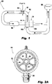
Fig. 1 is a schematic depiction of a fuel inerting system constructed in accordance with embodiments of the present invention, schematically showing an injector assembly; -
Fig. 2A is a downstream view of an injector assembly constructed in accordance with embodiments of the present invention, showing a nozzle within an outer housing; -
Fig. 2B is a side view of the injector assembly ofFig. 2A , showing first and second portions of the outer housing; -
Fig. 2C is an upstream view of the injector assembly ofFig. 2A , showing first and second portions of the outer housing; -
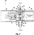
Fig. 3 is cross-sectional side elevation view of the fuel inerting system ofFig. 1 , showing the injector assembly ofFig. 2A connected to a duct with the nozzle body (not in cross-section) shown in the middle of the duct, the struts extending out of the page are shown in cross-section for sake of clarity; -
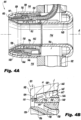
Fig. 4A is a cross-sectional side elevation view of a nozzle of the injector assembly ofFigs. 2A-2B constructed in accordance with the embodiments of the present invention, showing inner and outer gas flow paths; -
Fig. 4B is an enlarged cross-sectional side elevation view of a portion of the nozzle ofFig. 4A , showing a metering flow lip of the gas flow path; -
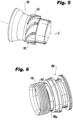
Fig. 5 is a perspective view of the core nozzle shell of the nozzle ofFig. 4A , showing the swirl vanes of the core nozzle shell; and -
Fig. 6 is a perspective view of the inner diameter liquid distributor of the nozzle ofFig. 4A , showing the distribution channels between the helical threads. - Reference will now be made to the drawings wherein like reference numerals identify similar structural features or aspects of the subject invention. For purposes of explanation and illustration, and not limitation, a partial view of an exemplary embodiment of a fuel inerting system in accordance with the invention is shown in
Fig. 1 and is designated generally byreference character 100. Other embodiments of fuel inerting systems in accordance with the invention, or aspects thereof, are provided inFigs. 2A-6 , as will be described. The systems and methods described herein can be used to facilitate fuel injecting/mixing in fuel inerting systems to vaporize fuel under arduous flight conditions. Nozzles described herein provide the desired mixing, and production of fine spray at very low flow rates while still maintaining contamination resistance. - As shown in
Fig. 1 , afuel inerting system 100 includes aduct 102 and aninjector assembly 104 positioned within theduct 102. Theinjector assembly 104 is schematically shown inFig. 1 , with more detail shown inFigs. 2A-2C and3 . Theinjector assembly 104 includes anozzle 101, which is also schematically shown inFig. 1 .Nozzle 101 is an encapsulated, aerating fuel atomizer that uses engine bleed air to finely atomize very cold fuel flowing at very low flow rates. Theinerting system 100 includes acatalytic reactor 106 positioned within theduct 102 downstream from theinjector assembly 104 and at least onefuel tank 108 downstream from thecatalytic reactor 106. Temperature and/orhumidity control system 110 is positioned downstream from thecatalytic reactor 106 and upstream from thenozzle 101. The temperature and/orhumidity control system 110 includes at least oneheat exchanger 110a and at least one water condenser 1 10b. A hot recirculation flow enters into thenozzle 101 after being heated by aheat exchanger 110a. The hot recirculation flow is mixed with a fresh air and fuel mixture (generated by nozzle 101) downstream from thenozzle 101 to generate a hot mixed/mixing fuel and gas mixture. The liquid/gas mixing bynozzle 101 is thorough but very efficient to maintain low system pressure loss. Moreover, the injection process withinnozzle 101 itself is configured to cause minimal drop on the recirculating flow, as pressure is required downstream from thenozzle 101 to push flow through thereactor 106,heat exchanger 110a andwater condenser 110b as well as provide flow to the fuel tank(s) 108. That hot mixed/mixing fuel and gas mixture goes into thecatalytic reactor 106 and exits as mostly nitrogen, carbon dioxide and water (in the form of a low reactivity gas). The mixture enteringcatalytic reactor 106 contains mostly nitrogen and thecatalytic reactor 106 reduces levels of oxygen that were present in the air before the reactor. The carbon dioxide and water are the remnants of the fuel. The oxygen in the air is reduced, not totally eliminated, to reduce reactivity. The mixture exiting the catalytic reactor is then dewatered by way ofwater condenser 110b before going to thefuel tank 108 to replace the air in the ullage offuel tank 108. - As shown in
Figs. 2A-2C and3 , theinjector assembly 104 includes anouter housing 112. Thenozzle 101 is positioned within theouter housing 112. Theinjector assembly 104 includes an annular outer housinggas flow path 114 radially outward from thenozzle 101 between aninner surface 116 of theouter housing 112 and anouter surface 118 of thenozzle 101. Annular outer housinggas flow path 114 facilitates a low-pressure flow of gas from the upstream recirculating gas path (labeled "recirculating air in" inFig. 3 ) to pass around an outer diameter ofnozzle 101. Thenozzle 101 defines acore conduit 134 radially inward from nozzle body.Conduit 134 defines a low pressure flow path that allows air from the upstream recirculating gas path (labeled "recirculating air in" inFig. 3 ) to pass through the center ofnozzle 101 in order to maximize air for mixing with the atomized fuel stream downstream of thenozzle 101, as shown schematically by centralrecirculating air arrow 167. In some embodiments, 50% or less of the "air in" flows throughcore conduit 134, depending on the size, while the remaining "air in" flows throughflow path 114. The direction offlow path 114 is schematically shown by the twoouter diameter arrows 167, which are labeled "recirculating air," inFig. 3 . Theinjector assembly 104 includes a plurality ofstruts 122 operatively connecting thenozzle 101 to theouter housing 112. The upstream and downstream shape ofstrut 122 keeps a uniform flow delivery throughgas flow path 114.Struts 112 have a narrow construction to reduce drag through 114.Outer housing 112 mounts between twoportions 102a and 102b ofduct 102. Theouter housing 112 includes afirst portion 124 and asecond portion 126. Thefirst portion 124 of theouter housing 112 is connected to theupstream portion 102a of theduct 102 and thesecond portion 126 of theouter housing 112 is connected to the downstream portion 102b of theduct 102. This configuration allows for ease of part exchange in the field. Eachhousing portion respective flanges 124a and 126a that facilitate exchangeability in the field. A pressure drop in theduct 102 from afirst position 160 upstream from thenozzle 101 to asecond position 162 downstream from thenozzle 101 is minimal, which accommodates the pressure needs downstream insystem 100. - As shown in
Figs. 3-4B , thenozzle 101 includes an annular pressurized outergas flow path 128 and an annular pressurized innergas flow path 130 radially inward from the outergas flow path 128, both the outergas flow path 128 and the innergas flow path 130 being air flow paths. The outergas flow path 128 has ametering flow lip 129 at an outlet thereof.Metering flow lip 129 is anannular flow lip 129.Metering flow lip 129 maximizes flow velocity through outergas flow path 128 while still maintaining the desired annular gap margins for contamination resistance, described in more detail below. Thenozzle 101 includes an annularliquid flow path 132 defined radially between the innergas flow path 130 and the outergas flow path 128. The innergas flow path 130 is defined between an annularinner heat shield 142 and an annularcore nozzle shell 136.Liquid flow path 132 is a liquid fuel flow path that is in fluid communication with afluid conduit 135.Fluid conduit 135 extends out ofnozzle 101 through one ofstruts 122 and connects to afluid inlet 137 defined throughsecond portion 126 ofhousing 112.Fluid inlet 137 includes a fitting orother conduit 171 attached thereto to provide fuel (or other fluid) tofuel inlet 137. Thecore conduit 134 is coaxial with the outergas flow path 128, the innergas flow path 130 and the outer housinggas flow path 114 about nozzle longitudinal axis A. - As shown in
Figs. 4A-4B , the outergas flow path 128 is defined between an annularouter nozzle shell 144 and at least one of an annularouter heat shield 146 or an annular outerdiameter liquid distributor 140. Theouter surface 118 of thenozzle 101 is also an outer surface ofouter nozzle shell 144, meaning that the outer housinggas flow path 114 is radially outward from theouter nozzle shell 144. The outergas flow path 128 is a converging non-swirling gas flow path. Theouter nozzle shell 144 is radially outward from theouter heat shield 146. Themetering flow lip 129 is defined by a radially inward extendingflange 129 of theouter nozzle shell 144.Flange 129 extends inwardly and perpendicular to the nozzle longitudinal axis A. An annular opening G defined in a radial direction between anedge surface 131 ofmetering flow lip 129 and anouter diameter surface 141 of the outerdiameter liquid distributor 140 is smaller than an upstream annular opening H defined in a radial direction between aninner diameter surface 145 of theouter nozzle shell 144 and theouter diameter surface 141 of the outerdiameter liquid distributor 140. The annular opening G is smaller than a further upstream annular opening J defined in a radial direction between theinner diameter surface 145 of theouter nozzle shell 144 and anouter diameter surface 147 of theouter heat shield 146. - With continued reference to
Fig. 4B , annular opening G is sized to be at or above a minimum annular gap threshold to ensure durability and contamination resistance. For example, sand ingested by the engine can find its way into the air stream utilized inmanifold 120, described below. Generally, small annular gaps for outergas flow path 128 and innergas flow path 130 are desired in order to meter the air flow through thenozzle 101 at a desired pressure. To avoid contamination issues, the downstreamgas flow paths nozzle 101, e.g. approximately 0.5 inches to 5 inches in diameter (1.2 to 12cm) , the minimum annular gap required for contamination may not be small enough to meet the desired pressure. As such, themetering flow lip 129, e.g. a flange, is used to accelerate air through the outergas flow path 128 without reducing the size of the annular opening G below the minimum threshold. The use of an inwardly extendingflange 129 to form the lip creates a "hook" like downstream end that deflects and thereby accelerates the flow through outer gas flow path 128 (this deflection is shown schematically by the flow arrows throughflow path 128 inFig. 4B ). This flow acceleration imposes an increase in pressure drop and reduces the effective gap height. The flow is thereby more energetic for mixing with a liquid fromliquid flow path 132 and liquid atomization but still meets the contamination resistance criteria. In some embodiments, the minimum threshold for annular opening G is approximately 0.020 inches wide (in the radial direction) (0.51mm) In the present embodiments shown in the drawings,outer nozzle shell 144 and thecore nozzle shell 136 terminate at respective downstream ends 150 and 139 at the same axial position relative to a longitudinal nozzle axis A. Those skilled in the art, however, will readily appreciate that, in some embodiments, adownstream end 150 ofouter nozzle shell 144 can terminate at an upstream or downstream axial position relative to thedownstream end 139 of thecore nozzle shell 136. - With continued reference to
Figs. 3-4B , theinjector assembly 104 includes a gas manifold, e.g. afresh air manifold 120. The fresh air is fed into thenozzle 101 from afresh air inlet 164 defined throughsecond portion 126 ofhousing 112 intomanifold 120.Fresh air inlet 164 is supplied via aconduit 165. Fresh air supply toconduit 165 could be bleed air from an aircraft engine which may be laden with particulate matter (i.e. sand) from the aircraft environment. In view of this,nozzle 101 is configured and adapted to withstand this particulate matter, for example by using a minimum gap threshold as described above.Manifold 120 then distributes the fresh air through thestruts 122 struts to anannular air distributor 166 ofnozzle 101. Theannular air distributor 166 is in fluid communication with the innergas flow path 130 and the outergas flow path 128 of thenozzle 101. The pressure drop frominlet 164 to outlets ofgas flow paths nozzle 101 is relatively low, e.g. ranging from 0.10 to 0.69 bar, such as 0.21 bar (0.5 to 10 psi, such as 3 psi). Liquid fuel fromliquid flow path 132 is thoroughly premixed with the fresh air supply from inner and outergas flow paths nozzle 101 is configured and adapted to mix 0.23 to 2.3 kg/h, e.g. 1.4 kg/h (0.5 to 5 pounds per hour (pph), e.g. 3 pph), or more, jet fuel between -40 to 121 °C (-40 to 250 °F), using large flow area contamination resistant annular flow channels, (e.g. having a width in a radial direction of 0.51mm (0.020 inches)), with high pressure engine bleed air (e.g. "fresh air" at about 3.4 bar, and 204 °C (50 psia, and 400 °F)) at about a 40:1 air to fuel by mass ratio (for the nozzle itself). It is contemplated that in some embodiments,nozzle 101 can mix fuel that is lower than -40° C (-40 °F). - Flow kinetic energy from
fuel nozzle 101 facilitates good atomization of the fuel, for example, to achieve an air-to-fuel mass ratio of 40:1. - It is also contemplated that the flow rate through
nozzle 101 and/or the mixing ratio can vary as determined by the requirements for the downstreamcatalytic converter 106. In traditional mixing devices, a low fuel flow rate his would usually require a very small pressure atomizing nozzle spray at a high fuel pressure, however these are susceptible to contamination when immersed in a hot air environment. - With continued reference to
Figs. 3-4B , the spray issued fromnozzle 101 is then thoroughly mixed with the recirculating air downstream fromnozzle 101, preferably without any supplementary mixing devices which would rob thesystem 100 of pressure required to circulate the mixture through thereactor 106 and temperature and/orhumidity control system 110. This further dilutes the previously reacted mixture (e.g. the air schematically shown as "Air In" inFig. 3 , which is the recirculating vitiated dilution gas that goes intocore conduit 134 and outer gas flow path 114) before entering thecatalytic reactor 106. The recirculating vitiated dilution gas is, for example, approximately at a pressure of 3.2 bar and 204 °C (47 psia and 400 °F). This is mixed with the fuel/fresh air mixture fromnozzle 101 at a ratio of about 10:1 recirculating vitiated dilution gas to fresh air and fuel flow, for an overall air (vitiated and fresh) to fuel ratio which could exceed 400:1. - With continued reference to
Figs. 3-4B , thecore conduit 134 is defined along an interior of the annularcore nozzle shell 136 and an annular upstreaminner core housing 168. Thecore conduit 134 and the outer housinggas flow path 114 are in fluid communication with a first gas source, e.g. a recirculating vitiated air source fromupstream portion 102a ofduct 102. A pressure drop across at least one of thecore conduit 134 or the outer housinggas flow path 114 from afirst position 160 upstream from thenozzle 101 to asecond position 162 downstream from thenozzle 101 is minimal, e.g. approximately a few inches of water pressure differential (a few hundred Pascals). The innergas flow path 130 and the outergas flow path 128 are in fluid communication with a second gas source (e.g. a pressurized fresh air source, such as engine bleed air) throughannular air distributor 166 as described above, which is different from the first gas source. In accordance with certain embodiments, the first gas source is at a lower pressure than the second gas source. - As shown in
Figs. 4A-4B and6 , theliquid flow path 132 is defined between an annular innerdiameter liquid distributor 138 and the annular outerdiameter liquid distributor 140. The innerdiameter liquid distributor 138 includeshelical threads 154, for example, threehelical threads 154.Helical threads 154 are defined on an outer cylindrical surface 138a of the innerdiameter liquid distributor 138 and form multiple high-swirl angle channels 170 as part ofliquid flow path 132. Those skilled in the art will readily appreciate that thethreads 154 can readily be defined on an inner cylindrical surface of the outerdiameter liquid distributor 140. Multiple highswirl angle channels 170 help distribute fuel to a large diameter annulus, e.g. approximately 0.5 inches to 5 inches in diameter (1.2cm to 12cm).Channels 170 are large in flow area to avoid contamination, for example, depending on the shape, they can be approximately 0.020 inches wide (in a radial direction) (0.51mm). - As shown in
Figs. 4A-4B and5 , the innergas flow path 130 is a diverging swirling gas flow path. Thecore nozzle shell 136 includesswirl vanes 152 extending therefrom.Swirl vanes 152 can be at approximately 60 degrees or greater with respect to an upstream direction of inner gas flow path 130 (which is approximately parallel to the direction of longitudinal axis A). Mixing and atomization processes require energy in the form of kinetic energy to impart shearing action on the flow to produce mixing and stretching of fuel film to produce drops. The high angle air swirler (defined by theinner heat shield 142 and the core nozzle shell 136) is used to pressurize air through innergas flow path 130, and energize (kinetically) the fuel atomizer and the downstream mixer. The high angle air swirler helps to thin out and circumferentially distribute the fuel film coming from theliquid fuel path 132. Those skilled in the art will readily appreciate that, in some embodiments, theswirl vanes 152 can extend from theinner heat shield 142. - As shown in
Fig. 3 , a mixing zone wherespray 148, schematically depicted (in part) with stippling inFig. 3 , andrecirculating air 167 mix together is defined downstream from anoutlet 150 of thenozzle 101 and can, in some embodiments, have an air-to-liquid ratio of 400 to 1. Thespray 148 is generally made up of fine droplets to facilitate evaporation fast enough before thecatalytic reactor 106. The uniform vapor permits optimal catalytic reactor performance and durability. For example, the droplet size in thespray leaving nozzle 101 can be in the order of twenty microns or less. The final gas mixture (e.g. the spray combined with the recirculating air) may be up to 400:1 gas to fuel by mass such that the temperature of the resulting gas be kept sufficiently low to be below the auto ignition temperature of jet fuel (approx. 204 °C (400 °F)), to thereby avoid inadvertently igniting any fuel/air mixture in the mixing process. Moreover,system 100 provides for an injection process where the spray issued fromnozzle 101 is narrow such that spray is kept off any conduits insystem 100. - The systems of the present invention, as described above and shown in the drawings, provide for fuel inerting systems and injector assemblies with superior properties including improved mixing with low pressure loss. While the apparatus of the subject invention have been shown and described with reference to preferred embodiments, those skilled in the art will readily appreciate that changes and/or modifications may be made thereto without departing from the scope of the subject invention as defined in the appended claims.
Claims (14)
- An inerting system (100) comprising:a duct (102);an injector assembly (104) positioned within the duct, wherein the injector assembly includes a nozzle (101) comprising:an outer gas flow path (128) having a metering flow lip (129) at an outlet thereof, the outer gas flow path adapted to be an air flow path;an inner gas flow path (130) radially inward from the outer gas flow path, the inner gas flow path adapted to be an air flow path;a liquid flow path (132) defined radially between the inner gas flow path and the outer gas flow path, the liquid flow path adapted to be a fuel flow path;a mixing zone for mixing air and liquid fuel is defined downstream of the nozzle; anda core conduit (134) defined radially inward from the inner gas flow path; the system further comprising:a catalytic reactor (106) positioned within the duct downstream from the injector assembly (104); andat least one tank (108) downstream from the catalytic reactor (106).
- The system as recited in claim 1, wherein the outer gas flow path is defined between an outer nozzle shell (144) and an outer heat shield (146).
- The system as recited in claim 1, wherein the outer gas flow path is defined between an outer nozzle shell (144) and an outer diameter liquid distributor (140).
- The system as recited in claim 2, wherein the outer nozzle shell (144) is radially outward from the outer heat shield (146).
- The system as recited in claim 2 or 4, wherein the metering flow lip (129) is defined by a radially inward extending flange (129) of the outer nozzle shell (144).
- The system as recited in claim 3, wherein an annular opening (G) defined between the metering flow lip (129) and an outer diameter surface (141) of the outer diameter liquid distributor (140) is smaller than an upstream annular opening (H) defined between an inner diameter surface (145) of the outer nozzle shell (144) and the outer diameter surface of the outer diameter liquid distributor (140).
- The system as recited in claim 6, wherein the annular opening (G) defined between the metering flow lip (129) and an outer diameter surface of the outer diameter liquid distributor (140) is smaller than a further upstream annular opening (J) defined between an inner diameter surface of the outer nozzle shell (144) and an outer diameter surface of an outer heat shield (146).
- The system as recited in any of claims 2 to 6, further comprising an outer housing gas flow path (128) defined radially outward from the outer nozzle shell (144).
- The system as recited in any preceding claim 1, wherein the core conduit (134) is defined within a core nozzle shell (136).
- The system as recited in claim 9, wherein the outer gas flow path is defined between an outer nozzle shell (144) and at least one of an outer heat shield (146) or an outer diameter liquid distributor (140), wherein the outer nozzle shell and the core nozzle shell (136) terminate at respective downstream ends at the same axial position relative to a longitudinal nozzle axis (A).
- The system according to any of claims 1 to 7, 9 or 10, wherein the injector assembly (104) comprises:an outer housing (112);wherein the nozzle (101) is positioned within the outer housing; andan outer housing gas flow path (114) defined radially outward from the nozzle between an inner surface (116) of the outer housing (112) and an outer surface (118) of the nozzle.
- The system as recited in claim 11, further comprising a gas manifold (120) in fluid communication with at least one of the inner gas flow path or the outer gas flow path of the nozzle.
- The system as recited in any preceding claim, wherein a pressure drop in the duct (102) from a first position upstream from the nozzle (101) to a second position downstream from the nozzle (101) is 750 Pa (three inches of water pressure) or less.
- The system as recited in any preceding claim, wherein the duct (102) includes an upstream portion (102a) and a downstream portion (102b), wherein the injector assembly includes the or an outer housing (112) with a first portion (124) and a second portion (126), wherein the first portion (124) of the outer housing (112) is connected to the upstream portion (102a) of the duct and the second portion (126) of the outer housing (112) is connected to the downstream portion of the duct (102).
Priority Applications (1)
| Application Number | Priority Date | Filing Date | Title |
|---|---|---|---|
| EP23159110.8A EP4206451A1 (en) | 2019-03-29 | 2019-11-29 | Mixing nozzle for a catalytic fuel tank inerting system for an aircraft |
Applications Claiming Priority (1)
| Application Number | Priority Date | Filing Date | Title |
|---|---|---|---|
| US16/370,731 US11253823B2 (en) | 2019-03-29 | 2019-03-29 | Mixing nozzles |
Related Child Applications (1)
| Application Number | Title | Priority Date | Filing Date |
|---|---|---|---|
| EP23159110.8A Division EP4206451A1 (en) | 2019-03-29 | 2019-11-29 | Mixing nozzle for a catalytic fuel tank inerting system for an aircraft |
Publications (2)
| Publication Number | Publication Date |
|---|---|
| EP3715605A1 EP3715605A1 (en) | 2020-09-30 |
| EP3715605B1 true EP3715605B1 (en) | 2023-03-01 |
Family
ID=68732962
Family Applications (2)
| Application Number | Title | Priority Date | Filing Date |
|---|---|---|---|
| EP19212589.6A Active EP3715605B1 (en) | 2019-03-29 | 2019-11-29 | Catalytic fuel tank inerting system for an aircraft |
| EP23159110.8A Pending EP4206451A1 (en) | 2019-03-29 | 2019-11-29 | Mixing nozzle for a catalytic fuel tank inerting system for an aircraft |
Family Applications After (1)
| Application Number | Title | Priority Date | Filing Date |
|---|---|---|---|
| EP23159110.8A Pending EP4206451A1 (en) | 2019-03-29 | 2019-11-29 | Mixing nozzle for a catalytic fuel tank inerting system for an aircraft |
Country Status (2)
| Country | Link |
|---|---|
| US (1) | US11253823B2 (en) |
| EP (2) | EP3715605B1 (en) |
Families Citing this family (4)
| Publication number | Priority date | Publication date | Assignee | Title |
|---|---|---|---|---|
| EP3766569A1 (en) * | 2019-07-18 | 2021-01-20 | Linde GmbH | Apparatus for dissolving gas into a liquid and method for producing the same |
| DE102021110616A1 (en) * | 2021-04-26 | 2022-10-27 | Rolls-Royce Deutschland Ltd & Co Kg | Fuel nozzle with different first and second outflow openings for providing a hydrogen-air mixture |
| CN114261349B (en) * | 2021-12-27 | 2024-03-08 | 洛阳理工学院 | Heat insulation chassis device for fire-fighting robot |
| CN217152127U (en) * | 2022-05-05 | 2022-08-09 | 广东华控汽车科技有限公司 | Electric control throttle valve with improved structure |
Family Cites Families (15)
| Publication number | Priority date | Publication date | Assignee | Title |
|---|---|---|---|---|
| GB1395691A (en) | 1973-10-05 | 1975-05-29 | Garrett Corp | Fuel tank inerting system |
| US4139157A (en) * | 1976-09-02 | 1979-02-13 | Parker-Hannifin Corporation | Dual air-blast fuel nozzle |
| DE69506308T2 (en) * | 1994-04-20 | 1999-08-26 | Rolls-Royce Plc | Fuel injector for gas turbine engines |
| US6389815B1 (en) * | 2000-09-08 | 2002-05-21 | General Electric Company | Fuel nozzle assembly for reduced exhaust emissions |
| US7926744B2 (en) | 2008-02-21 | 2011-04-19 | Delavan Inc | Radially outward flowing air-blast fuel injector for gas turbine engine |
| JP5472863B2 (en) | 2009-06-03 | 2014-04-16 | 独立行政法人 宇宙航空研究開発機構 | Staging fuel nozzle |
| US8726668B2 (en) | 2010-12-17 | 2014-05-20 | General Electric Company | Fuel atomization dual orifice fuel nozzle |
| US8925325B2 (en) | 2011-03-18 | 2015-01-06 | Delavan Inc. | Recirculating product injection nozzle |
| JP5924618B2 (en) * | 2012-06-07 | 2016-05-25 | 川崎重工業株式会社 | Fuel injection device |
| JP5988261B2 (en) * | 2012-06-07 | 2016-09-07 | 川崎重工業株式会社 | Fuel injection device |
| US9939157B2 (en) * | 2015-03-10 | 2018-04-10 | General Electric Company | Hybrid air blast fuel nozzle |
| US9927126B2 (en) * | 2015-06-10 | 2018-03-27 | General Electric Company | Prefilming air blast (PAB) pilot for low emissions combustors |
| US10054093B2 (en) * | 2016-01-05 | 2018-08-21 | Solar Turbines Incorporated | Fuel injector with a center body assembly for liquid prefilm injection |
| DE102017217329A1 (en) * | 2017-09-28 | 2019-03-28 | Rolls-Royce Deutschland Ltd & Co Kg | Nozzle with axially projecting air guide for a combustion chamber of an engine |
| US20200309376A1 (en) * | 2019-03-29 | 2020-10-01 | Delavan Inc. | Mixing nozzles |
-
2019
- 2019-03-29 US US16/370,731 patent/US11253823B2/en active Active
- 2019-11-29 EP EP19212589.6A patent/EP3715605B1/en active Active
- 2019-11-29 EP EP23159110.8A patent/EP4206451A1/en active Pending
Also Published As
| Publication number | Publication date |
|---|---|
| EP3715605A1 (en) | 2020-09-30 |
| US11253823B2 (en) | 2022-02-22 |
| US20200306703A1 (en) | 2020-10-01 |
| EP4206451A1 (en) | 2023-07-05 |
Similar Documents
| Publication | Publication Date | Title |
|---|---|---|
| EP3715605A1 (en) | Mixing nozzle for a catalytic fuel tank inerting system for an aircraft | |
| US9951955B2 (en) | Annular combustion chamber for a turbine engine | |
| US4198815A (en) | Central injection fuel carburetor | |
| US6986255B2 (en) | Piloted airblast lean direct fuel injector with modified air splitter | |
| US5934555A (en) | Pressure atomizer nozzle | |
| US7568345B2 (en) | Effervescence injector for an aero-mechanical system for injecting air/fuel mixture into a turbomachine combustion chamber | |
| US3853273A (en) | Axial swirler central injection carburetor | |
| US4070826A (en) | Low pressure fuel injection system | |
| JP3662023B2 (en) | Fuel nozzle introduced from tangential direction | |
| US5713205A (en) | Air atomized discrete jet liquid fuel injector and method | |
| US10883719B2 (en) | Prefilming fuel/air mixer | |
| US11649964B2 (en) | Fuel injector assembly for a turbine engine | |
| JP2011247576A (en) | Hybrid prefilming airblast, prevaporizing, lean-premixing dual-fuel nozzle for gas turbine combustor | |
| EP3715604A1 (en) | Mixing nozzle for a catalytic fuel tank inerting system for an aircraft | |
| WO2001051787A1 (en) | Piloted airblast lean direct fuel injector | |
| US5573392A (en) | Method and device for distributing fuel in a burner suitable for both liquid and gaseous fuels | |
| EP0283422A2 (en) | Airblast fuel atomizer | |
| CN108351104A (en) | The aerodynamics spraying system with the mixing of improved air/fuel for aircraft turbine engine | |
| CN109827192A (en) | A kind of air atomizer spray nozzle of double oil circuits bispin flow structure | |
| EP0762057B1 (en) | Mixing device for fuel and air for gas turbine combustors | |
| CN105772264A (en) | Method for producing a spray jet, and two-component nozzle | |
| WO1995016881A1 (en) | Method and apparatus for atomizing liquid fuel | |
| JP2000028111A (en) | Fuel injector and burner using the same | |
| DE2641605A1 (en) | FUEL EQUIPMENT WITH CENTRAL INJECTION | |
| US20170370590A1 (en) | Fuel nozzle |
Legal Events
| Date | Code | Title | Description |
|---|---|---|---|
| PUAI | Public reference made under article 153(3) epc to a published international application that has entered the european phase |
Free format text: ORIGINAL CODE: 0009012 |
|
| STAA | Information on the status of an ep patent application or granted ep patent |
Free format text: STATUS: THE APPLICATION HAS BEEN PUBLISHED |
|
| AK | Designated contracting states |
Kind code of ref document: A1 Designated state(s): AL AT BE BG CH CY CZ DE DK EE ES FI FR GB GR HR HU IE IS IT LI LT LU LV MC MK MT NL NO PL PT RO RS SE SI SK SM TR |
|
| AX | Request for extension of the european patent |
Extension state: BA ME |
|
| STAA | Information on the status of an ep patent application or granted ep patent |
Free format text: STATUS: REQUEST FOR EXAMINATION WAS MADE |
|
| 17P | Request for examination filed |
Effective date: 20210329 |
|
| RBV | Designated contracting states (corrected) |
Designated state(s): AL AT BE BG CH CY CZ DE DK EE ES FI FR GB GR HR HU IE IS IT LI LT LU LV MC MK MT NL NO PL PT RO RS SE SI SK SM TR |
|
| GRAP | Despatch of communication of intention to grant a patent |
Free format text: ORIGINAL CODE: EPIDOSNIGR1 |
|
| STAA | Information on the status of an ep patent application or granted ep patent |
Free format text: STATUS: GRANT OF PATENT IS INTENDED |
|
| RIC1 | Information provided on ipc code assigned before grant |
Ipc: B64D 13/00 20060101ALI20220301BHEP Ipc: B01J 19/26 20060101ALI20220301BHEP Ipc: B01J 4/00 20060101ALI20220301BHEP Ipc: A62C 99/00 20100101ALI20220301BHEP Ipc: F23D 11/10 20060101ALI20220301BHEP Ipc: F23K 5/08 20060101ALI20220301BHEP Ipc: B64D 37/32 20060101ALI20220301BHEP Ipc: F23D 11/24 20060101ALI20220301BHEP Ipc: F23D 11/38 20060101ALI20220301BHEP Ipc: A62C 3/08 20060101ALI20220301BHEP Ipc: B01J 19/14 20060101ALI20220301BHEP Ipc: B60K 15/03 20060101ALI20220301BHEP Ipc: F02C 7/22 20060101AFI20220301BHEP |
|
| INTG | Intention to grant announced |
Effective date: 20220404 |
|
| RAP3 | Party data changed (applicant data changed or rights of an application transferred) |
Owner name: COLLINS ENGINE NOZZLES, INC. |
|
| GRAJ | Information related to disapproval of communication of intention to grant by the applicant or resumption of examination proceedings by the epo deleted |
Free format text: ORIGINAL CODE: EPIDOSDIGR1 |
|
| STAA | Information on the status of an ep patent application or granted ep patent |
Free format text: STATUS: REQUEST FOR EXAMINATION WAS MADE |
|
| INTC | Intention to grant announced (deleted) | ||
| GRAP | Despatch of communication of intention to grant a patent |
Free format text: ORIGINAL CODE: EPIDOSNIGR1 |
|
| STAA | Information on the status of an ep patent application or granted ep patent |
Free format text: STATUS: GRANT OF PATENT IS INTENDED |
|
| INTG | Intention to grant announced |
Effective date: 20220920 |
|
| RIN1 | Information on inventor provided before grant (corrected) |
Inventor name: WILLIAMS, BRANDON PHILIP Inventor name: PROCIW, LEV ALEXANDER Inventor name: BUELOW, PHILIP E. Inventor name: RYON, JASON A. |
|
| GRAS | Grant fee paid |
Free format text: ORIGINAL CODE: EPIDOSNIGR3 |
|
| GRAA | (expected) grant |
Free format text: ORIGINAL CODE: 0009210 |
|
| STAA | Information on the status of an ep patent application or granted ep patent |
Free format text: STATUS: THE PATENT HAS BEEN GRANTED |
|
| AK | Designated contracting states |
Kind code of ref document: B1 Designated state(s): AL AT BE BG CH CY CZ DE DK EE ES FI FR GB GR HR HU IE IS IT LI LT LU LV MC MK MT NL NO PL PT RO RS SE SI SK SM TR |
|
| REG | Reference to a national code |
Ref country code: GB Ref legal event code: FG4D |
|
| REG | Reference to a national code |
Ref country code: CH Ref legal event code: EP Ref country code: AT Ref legal event code: REF Ref document number: 1551120 Country of ref document: AT Kind code of ref document: T Effective date: 20230315 |
|
| REG | Reference to a national code |
Ref country code: DE Ref legal event code: R096 Ref document number: 602019025788 Country of ref document: DE |
|
| REG | Reference to a national code |
Ref country code: IE Ref legal event code: FG4D |
|
| REG | Reference to a national code |
Ref country code: LT Ref legal event code: MG9D |
|
| REG | Reference to a national code |
Ref country code: NL Ref legal event code: MP Effective date: 20230301 |
|
| P01 | Opt-out of the competence of the unified patent court (upc) registered |
Effective date: 20230530 |
|
| PG25 | Lapsed in a contracting state [announced via postgrant information from national office to epo] |
Ref country code: RS Free format text: LAPSE BECAUSE OF FAILURE TO SUBMIT A TRANSLATION OF THE DESCRIPTION OR TO PAY THE FEE WITHIN THE PRESCRIBED TIME-LIMIT Effective date: 20230301 Ref country code: NO Free format text: LAPSE BECAUSE OF FAILURE TO SUBMIT A TRANSLATION OF THE DESCRIPTION OR TO PAY THE FEE WITHIN THE PRESCRIBED TIME-LIMIT Effective date: 20230601 Ref country code: LV Free format text: LAPSE BECAUSE OF FAILURE TO SUBMIT A TRANSLATION OF THE DESCRIPTION OR TO PAY THE FEE WITHIN THE PRESCRIBED TIME-LIMIT Effective date: 20230301 Ref country code: LT Free format text: LAPSE BECAUSE OF FAILURE TO SUBMIT A TRANSLATION OF THE DESCRIPTION OR TO PAY THE FEE WITHIN THE PRESCRIBED TIME-LIMIT Effective date: 20230301 Ref country code: HR Free format text: LAPSE BECAUSE OF FAILURE TO SUBMIT A TRANSLATION OF THE DESCRIPTION OR TO PAY THE FEE WITHIN THE PRESCRIBED TIME-LIMIT Effective date: 20230301 Ref country code: ES Free format text: LAPSE BECAUSE OF FAILURE TO SUBMIT A TRANSLATION OF THE DESCRIPTION OR TO PAY THE FEE WITHIN THE PRESCRIBED TIME-LIMIT Effective date: 20230301 |
|
| REG | Reference to a national code |
Ref country code: AT Ref legal event code: MK05 Ref document number: 1551120 Country of ref document: AT Kind code of ref document: T Effective date: 20230301 |
|
| PG25 | Lapsed in a contracting state [announced via postgrant information from national office to epo] |
Ref country code: SE Free format text: LAPSE BECAUSE OF FAILURE TO SUBMIT A TRANSLATION OF THE DESCRIPTION OR TO PAY THE FEE WITHIN THE PRESCRIBED TIME-LIMIT Effective date: 20230301 Ref country code: PL Free format text: LAPSE BECAUSE OF FAILURE TO SUBMIT A TRANSLATION OF THE DESCRIPTION OR TO PAY THE FEE WITHIN THE PRESCRIBED TIME-LIMIT Effective date: 20230301 Ref country code: NL Free format text: LAPSE BECAUSE OF FAILURE TO SUBMIT A TRANSLATION OF THE DESCRIPTION OR TO PAY THE FEE WITHIN THE PRESCRIBED TIME-LIMIT Effective date: 20230301 Ref country code: GR Free format text: LAPSE BECAUSE OF FAILURE TO SUBMIT A TRANSLATION OF THE DESCRIPTION OR TO PAY THE FEE WITHIN THE PRESCRIBED TIME-LIMIT Effective date: 20230602 Ref country code: FI Free format text: LAPSE BECAUSE OF FAILURE TO SUBMIT A TRANSLATION OF THE DESCRIPTION OR TO PAY THE FEE WITHIN THE PRESCRIBED TIME-LIMIT Effective date: 20230301 |
|
| PG25 | Lapsed in a contracting state [announced via postgrant information from national office to epo] |
Ref country code: SM Free format text: LAPSE BECAUSE OF FAILURE TO SUBMIT A TRANSLATION OF THE DESCRIPTION OR TO PAY THE FEE WITHIN THE PRESCRIBED TIME-LIMIT Effective date: 20230301 Ref country code: RO Free format text: LAPSE BECAUSE OF FAILURE TO SUBMIT A TRANSLATION OF THE DESCRIPTION OR TO PAY THE FEE WITHIN THE PRESCRIBED TIME-LIMIT Effective date: 20230301 Ref country code: PT Free format text: LAPSE BECAUSE OF FAILURE TO SUBMIT A TRANSLATION OF THE DESCRIPTION OR TO PAY THE FEE WITHIN THE PRESCRIBED TIME-LIMIT Effective date: 20230703 Ref country code: EE Free format text: LAPSE BECAUSE OF FAILURE TO SUBMIT A TRANSLATION OF THE DESCRIPTION OR TO PAY THE FEE WITHIN THE PRESCRIBED TIME-LIMIT Effective date: 20230301 Ref country code: CZ Free format text: LAPSE BECAUSE OF FAILURE TO SUBMIT A TRANSLATION OF THE DESCRIPTION OR TO PAY THE FEE WITHIN THE PRESCRIBED TIME-LIMIT Effective date: 20230301 Ref country code: AT Free format text: LAPSE BECAUSE OF FAILURE TO SUBMIT A TRANSLATION OF THE DESCRIPTION OR TO PAY THE FEE WITHIN THE PRESCRIBED TIME-LIMIT Effective date: 20230301 |
|
| PG25 | Lapsed in a contracting state [announced via postgrant information from national office to epo] |
Ref country code: SK Free format text: LAPSE BECAUSE OF FAILURE TO SUBMIT A TRANSLATION OF THE DESCRIPTION OR TO PAY THE FEE WITHIN THE PRESCRIBED TIME-LIMIT Effective date: 20230301 Ref country code: IS Free format text: LAPSE BECAUSE OF FAILURE TO SUBMIT A TRANSLATION OF THE DESCRIPTION OR TO PAY THE FEE WITHIN THE PRESCRIBED TIME-LIMIT Effective date: 20230701 |
|
| REG | Reference to a national code |
Ref country code: DE Ref legal event code: R097 Ref document number: 602019025788 Country of ref document: DE |
|
| PLBE | No opposition filed within time limit |
Free format text: ORIGINAL CODE: 0009261 |
|
| STAA | Information on the status of an ep patent application or granted ep patent |
Free format text: STATUS: NO OPPOSITION FILED WITHIN TIME LIMIT |
|
| PG25 | Lapsed in a contracting state [announced via postgrant information from national office to epo] |
Ref country code: SI Free format text: LAPSE BECAUSE OF FAILURE TO SUBMIT A TRANSLATION OF THE DESCRIPTION OR TO PAY THE FEE WITHIN THE PRESCRIBED TIME-LIMIT Effective date: 20230301 Ref country code: DK Free format text: LAPSE BECAUSE OF FAILURE TO SUBMIT A TRANSLATION OF THE DESCRIPTION OR TO PAY THE FEE WITHIN THE PRESCRIBED TIME-LIMIT Effective date: 20230301 |
|
| 26N | No opposition filed |
Effective date: 20231204 |
|
| PG25 | Lapsed in a contracting state [announced via postgrant information from national office to epo] |
Ref country code: IT Free format text: LAPSE BECAUSE OF FAILURE TO SUBMIT A TRANSLATION OF THE DESCRIPTION OR TO PAY THE FEE WITHIN THE PRESCRIBED TIME-LIMIT Effective date: 20230301 |
|
| REG | Reference to a national code |
Ref country code: CH Ref legal event code: PL |
|
| PG25 | Lapsed in a contracting state [announced via postgrant information from national office to epo] |
Ref country code: MC Free format text: LAPSE BECAUSE OF FAILURE TO SUBMIT A TRANSLATION OF THE DESCRIPTION OR TO PAY THE FEE WITHIN THE PRESCRIBED TIME-LIMIT Effective date: 20230301 |
|
| PG25 | Lapsed in a contracting state [announced via postgrant information from national office to epo] |
Ref country code: LU Free format text: LAPSE BECAUSE OF NON-PAYMENT OF DUE FEES Effective date: 20231129 |
|
| PG25 | Lapsed in a contracting state [announced via postgrant information from national office to epo] |
Ref country code: CH Free format text: LAPSE BECAUSE OF NON-PAYMENT OF DUE FEES Effective date: 20231130 |
|
| PG25 | Lapsed in a contracting state [announced via postgrant information from national office to epo] |
Ref country code: MC Free format text: LAPSE BECAUSE OF FAILURE TO SUBMIT A TRANSLATION OF THE DESCRIPTION OR TO PAY THE FEE WITHIN THE PRESCRIBED TIME-LIMIT Effective date: 20230301 Ref country code: LU Free format text: LAPSE BECAUSE OF NON-PAYMENT OF DUE FEES Effective date: 20231129 Ref country code: CH Free format text: LAPSE BECAUSE OF NON-PAYMENT OF DUE FEES Effective date: 20231130 |
|
| REG | Reference to a national code |
Ref country code: BE Ref legal event code: MM Effective date: 20231130 |
|
| REG | Reference to a national code |
Ref country code: IE Ref legal event code: MM4A |
|
| PG25 | Lapsed in a contracting state [announced via postgrant information from national office to epo] |
Ref country code: IE Free format text: LAPSE BECAUSE OF NON-PAYMENT OF DUE FEES Effective date: 20231129 |
|
| PG25 | Lapsed in a contracting state [announced via postgrant information from national office to epo] |
Ref country code: BE Free format text: LAPSE BECAUSE OF NON-PAYMENT OF DUE FEES Effective date: 20231130 |
|
| PG25 | Lapsed in a contracting state [announced via postgrant information from national office to epo] |
Ref country code: IE Free format text: LAPSE BECAUSE OF NON-PAYMENT OF DUE FEES Effective date: 20231129 Ref country code: BE Free format text: LAPSE BECAUSE OF NON-PAYMENT OF DUE FEES Effective date: 20231130 |
|
| PG25 | Lapsed in a contracting state [announced via postgrant information from national office to epo] |
Ref country code: BG Free format text: LAPSE BECAUSE OF FAILURE TO SUBMIT A TRANSLATION OF THE DESCRIPTION OR TO PAY THE FEE WITHIN THE PRESCRIBED TIME-LIMIT Effective date: 20230301 |
|
| PG25 | Lapsed in a contracting state [announced via postgrant information from national office to epo] |
Ref country code: BG Free format text: LAPSE BECAUSE OF FAILURE TO SUBMIT A TRANSLATION OF THE DESCRIPTION OR TO PAY THE FEE WITHIN THE PRESCRIBED TIME-LIMIT Effective date: 20230301 |
|
| PG25 | Lapsed in a contracting state [announced via postgrant information from national office to epo] |
Ref country code: CY Free format text: LAPSE BECAUSE OF FAILURE TO SUBMIT A TRANSLATION OF THE DESCRIPTION OR TO PAY THE FEE WITHIN THE PRESCRIBED TIME-LIMIT; INVALID AB INITIO Effective date: 20191129 |
|
| PG25 | Lapsed in a contracting state [announced via postgrant information from national office to epo] |
Ref country code: HU Free format text: LAPSE BECAUSE OF FAILURE TO SUBMIT A TRANSLATION OF THE DESCRIPTION OR TO PAY THE FEE WITHIN THE PRESCRIBED TIME-LIMIT; INVALID AB INITIO Effective date: 20191129 |
|
| PG25 | Lapsed in a contracting state [announced via postgrant information from national office to epo] |
Ref country code: TR Free format text: LAPSE BECAUSE OF FAILURE TO SUBMIT A TRANSLATION OF THE DESCRIPTION OR TO PAY THE FEE WITHIN THE PRESCRIBED TIME-LIMIT Effective date: 20230301 |
|
| PGFP | Annual fee paid to national office [announced via postgrant information from national office to epo] |
Ref country code: DE Payment date: 20251022 Year of fee payment: 7 |
|
| PGFP | Annual fee paid to national office [announced via postgrant information from national office to epo] |
Ref country code: GB Payment date: 20251022 Year of fee payment: 7 |
|
| PGFP | Annual fee paid to national office [announced via postgrant information from national office to epo] |
Ref country code: FR Payment date: 20251022 Year of fee payment: 7 |