EP3715549A1 - Joint member for panels - Google Patents
Joint member for panels Download PDFInfo
- Publication number
- EP3715549A1 EP3715549A1 EP20166013.1A EP20166013A EP3715549A1 EP 3715549 A1 EP3715549 A1 EP 3715549A1 EP 20166013 A EP20166013 A EP 20166013A EP 3715549 A1 EP3715549 A1 EP 3715549A1
- Authority
- EP
- European Patent Office
- Prior art keywords
- panel
- joint member
- edge
- connecting portions
- panels
- Prior art date
- Legal status (The legal status is an assumption and is not a legal conclusion. Google has not performed a legal analysis and makes no representation as to the accuracy of the status listed.)
- Granted
Links
Images




Classifications
-
- E—FIXED CONSTRUCTIONS
- E04—BUILDING
- E04B—GENERAL BUILDING CONSTRUCTIONS; WALLS, e.g. PARTITIONS; ROOFS; FLOORS; CEILINGS; INSULATION OR OTHER PROTECTION OF BUILDINGS
- E04B1/00—Constructions in general; Structures which are not restricted either to walls, e.g. partitions, or floors or ceilings or roofs
- E04B1/38—Connections for building structures in general
- E04B1/61—Connections for building structures in general of slab-shaped building elements with each other
- E04B1/6108—Connections for building structures in general of slab-shaped building elements with each other the frontal surfaces of the slabs connected together
- E04B1/612—Connections for building structures in general of slab-shaped building elements with each other the frontal surfaces of the slabs connected together by means between frontal surfaces
- E04B1/6145—Connections for building structures in general of slab-shaped building elements with each other the frontal surfaces of the slabs connected together by means between frontal surfaces with recesses in both frontal surfaces co-operating with an additional connecting element
-
- F—MECHANICAL ENGINEERING; LIGHTING; HEATING; WEAPONS; BLASTING
- F16—ENGINEERING ELEMENTS AND UNITS; GENERAL MEASURES FOR PRODUCING AND MAINTAINING EFFECTIVE FUNCTIONING OF MACHINES OR INSTALLATIONS; THERMAL INSULATION IN GENERAL
- F16B—DEVICES FOR FASTENING OR SECURING CONSTRUCTIONAL ELEMENTS OR MACHINE PARTS TOGETHER, e.g. NAILS, BOLTS, CIRCLIPS, CLAMPS, CLIPS OR WEDGES; JOINTS OR JOINTING
- F16B5/00—Joining sheets or plates, e.g. panels, to one another or to strips or bars parallel to them
- F16B5/0004—Joining sheets, plates or panels in abutting relationship
- F16B5/0008—Joining sheets, plates or panels in abutting relationship by moving the sheets, plates or panels substantially in their own plane, perpendicular to the abutting edge
- F16B5/0024—Joining sheets, plates or panels in abutting relationship by moving the sheets, plates or panels substantially in their own plane, perpendicular to the abutting edge the sheets, plates or panels having holes, e.g. for dowel- type connections
-
- E—FIXED CONSTRUCTIONS
- E04—BUILDING
- E04B—GENERAL BUILDING CONSTRUCTIONS; WALLS, e.g. PARTITIONS; ROOFS; FLOORS; CEILINGS; INSULATION OR OTHER PROTECTION OF BUILDINGS
- E04B1/00—Constructions in general; Structures which are not restricted either to walls, e.g. partitions, or floors or ceilings or roofs
- E04B1/02—Structures consisting primarily of load-supporting, block-shaped, or slab-shaped elements
- E04B1/10—Structures consisting primarily of load-supporting, block-shaped, or slab-shaped elements the elements consisting of wood
Definitions
- This invention relates in general to the sector of constructions and in particular the subject matter of this invention is a joint member for panels.
- One specific field of use of this invention is the building sector, in particular for wooden buildings.
- the walls of a wooden building are made using prefabricated panels, made of wood (for example multi-layered wood or X-LAM type laminated wood panels), which are installed by positioning them vertically and joining them to each other. Since the width of each panel is limited by the production and transportation needs involved and therefore the width of the panel is less than the desired width of the wall, each wall is formed by a plurality of panels alongside each other so as to obtain the desired width.
- wood for example multi-layered wood or X-LAM type laminated wood panels
- the mechanical connections between the panels and the foundation base, and between the panels themselves, are made for example by means of metal brackets or plates to be fixed to the faces of the panels and by fixing screws with various inclinations according to requirements.
- the prior art methods involve drawbacks regarding the assembling of wooden walls in which there must be an opening for a door or for a window. That opening is laterally delimited by two lateral panels, which act as uprights, and is delimited at the top by a panel which acts as a crosspiece or architrave and which is constrained to the two lateral panels.
- the lateral panels hold the upper panel spaced from the ground and discharge to the ground the load that the structures above apply on the upper panel.
- the mechanical connection between the lateral panels and the upper panel is required to be strong, suitable for transferring loads and carefully made.
- One prior art method involves shaping the upper portion of the sides of the lateral panels in such a way as to create supports for the upper panel.
- the upper panel is mechanically connected to the lateral panels by means of fixing screws inserted from above into holes made in the thickness of the panels and having an inclination of approximately 45° relative to the vertical direction. The screws fix the upper panel to the lateral panels. See Figure 1A with regard to this.
- the opening is also delimited at the bottom by a lower panel which in turn is fixed to the lateral panels by means of screws inserted into holes made in the thickness of the panels, at approximately 45° relative to the vertical direction.
- the fixing screws may be positioned differently: for example they may be inserted not from above but obliquely from the faces of the panels, or from above but with a different angle.
- all of these prior art methods have the disadvantage that the obtained result greatly depends on the professional expertise of the operators and on the precision of their assembling work during installation. For example, holes made with incorrect inclinations or in unsuitable positions may make the connection by fixing screws much weaker than expected.
- the technical purpose which forms the basis of this invention is to provide a joint member for panels which allows the panels to be mechanically connected to each other with methods which overcome the drawbacks of the prior art, or at least to provide a joint member for panels which offers an alternative solution to the currently known solutions.
- This invention also relates to an assembly (in particular a wall of a building, or a floor of a building) comprising panels which are connected to each other by joint members according to this invention.
- the joint member has a body equipped with at least four connecting portions (or fixing portions) each having a respective seat intended to receive a fixing element.
- each seat represents a point at which the joint member is fixable to a panel and the respective connecting portion is a body part which is configured for receiving the fixing element and for mechanically operating in conjunction with the latter and with the panel.
- the seats are spaced from each other and, in a plan view of the joint member, are positioned at the vertices of a quadrilateral.
- the connecting portions are fixable in pairs to the respective panels: in use, the fixing member is positioned in a position interposed between the first panel and the second panel, in a joint region in which a side or edge of the first panel is alongside a side or edge of the second panel; two connecting portions are fixed to the first panel; the other two connecting portions are fixed to the second panel.
- the joint member is shaped in such a way that its seats for the fixing elements are located, in pairs, on opposite sides of its body and those sides are located on opposite faces of the assembly formed by the panels which are alongside each other. That is useful for facilitating assembling operations: the sides of the joint member remain accessible when the latter is positioned between the panels and therefore the operator can easily position the fixing elements in the seats, if necessary also making the corresponding holes in the panels.
- the holes to be made during installation have a limited depth, determined by the length (variable according to requirements) of the fixing element to be received. They do not extend at all from the top of the upper panel and for a significant stretch of its height, as in contrast is necessary for the prior art shown in Figure 1A . This greatly simplifies the operations to be performed during installation.
- the joint member is usable for joining panels with straight sides.
- hollows or recesses can be made, in the thickness of the respective panel, for receiving a corresponding part of the joint member.
- the joint member may be completely housed in those hollows, without projecting from the faces of the assembly and without constituting a thickness between the sides or edges.
- the hollows or recesses can be easily made by milling and in particular can be made in the factory, thereby minimising the operations to be performed during installation.
- the simplification of the operations to be performed during installation greatly reduces both the possibility of errors by the operators, and the influence of their professional expertise and precision on the obtained result.
- the risk of difference between the wall installed and the design specifications is much reduced. Therefore, the use of a joint member according to this invention is useful for ensuring that the wall installed has, in structural and earthquake resistance terms, characteristics which are reproducible and corresponding to those of the design. This allows to disengage the obtained result as far as possible from the margin of uncertainty due to the work of the operators who assembled the wall during installation.
- the connecting portions intended for the same panel between them form a housing
- joint member One specific field of use of the joint member according to this invention is that of wooden structures, in which the joint member is usable for multi-layered wood or laminated wood panels, in particular of the X-LAM or CLT (Cross Laminated Timber) type.
- the seats for the fixing elements have central longitudinal axes which are slanting [not in the same plane] relative to each other and have projections which, in a view orthogonal to the plan view of the joint member, diverge in the direction coming out of the faces which face the same panel.
- the fixing elements inserted into the panel affect a greater volume of the panel, they involve a greater number of fibres of the wood and they more effectively distribute the stresses in a more extensive zone of the panel. Therefore, a very strong joint is obtained.
- joint member according to this invention may be used for panels of any type and made of any material, not necessarily in the building sector.
- Figure 1A shows a known method for making a wall made of wooden panels in which an opening for a door or for a window is required.
- the wall in Figure 1A is shown during an assembling step.
- Two lateral panels 91, 93, one upper panel 92 and if necessary one lower panel 94 delimit an opening 90 for a door or for a window.
- Supports 95 are obtained in the sides of the lateral panels 91, 93 by shaping the self-same sides.
- the upper panel 92 is rested laterally on the supports 95.
- the upper panel 92 is constrained to the lateral panels 91, 93 by means of screws 96: the screws 96 are inserted into holes 97, made at approximately 45° relative to the vertical direction.
- the holes 97 pass through the height of the upper panel 92 and penetrate the sides of the lateral panels 91, 93.
- the holes 97 are made and the screws 96 are inserted from above.
- the screws 96 inserted into the bottom of the holes 97 therefore connect the upper panel 92 to the lateral panels 91, 93.
- a similar fixing with screws 96 in inclined holes 97 is also used for the lower panel 94.
- the panels may be constrained to each other by means of pierced flat plates 98.
- the lower panel 94 is constrained to the lateral panels 91, 93 also by means of said pierced flat plates 98, which are fixed with screws to the faces of the panels.
- the flat plates 98 straddle the face of the panel 94 and the face of the other panel alongside 91, 93, parallel to the faces themselves.
- the fixing screws 96 may be positioned differently: for example they may be inserted not from above but obliquely relative to the faces of the panels, or they may be inserted from above but with a different inclination or a different position.
- Figures 1B and 1C should be viewed with regard to this, since for illustrative purposes they show three screws 96 with different directions of insertion: two will be inserted into holes which start from the face of the upper panel 92 or of the lateral panel 93, the other will be inserted into a hole which starts from the top of the lateral panel 93 rather than from the top of the upper panel 92 as in Figure 1A .
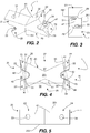
- FIG. 2 to 9 A first embodiment of a joint member for panels according to this invention is shown in Figures 2 to 9 , where the joint member is labelled with the reference number 1.
- the joint member 1 is intended to mechanically connect a first panel and a second panel to each other.
- the joint member 1 is a structural connecting element, which is used for assembling a structure formed by panels and remains incorporated in the structure itself, constituting a joint which constrains the two panels to each other.
- Figures 10 to 16 show, by way of example, an assembly comprising panels joined to each other by means of joint members according to this invention.
- a first panel is labelled with the reference number 51
- a second panel is labelled with the reference number 52
- a third panel is labelled with the reference number 53.
- Figure 16 shows a wall of wooden panels in which an opening for a door or for a window is present. The differences compared with the prior art shown in Figures 1A, 1B and 1C are immediately evident.
- the joint member 1 is intended to be positioned in a position interposed between the first panel 51 and the second panel 52, in a joint region 50 in which a side or edge 511 of the first panel 51 is alongside a side or edge 521 of the second panel 52.
- the joint member 1 has stiffness and mechanical strength suitable for the purpose of keeping the panels 51, 52 connected to each other in a predetermined position and of transmitting between them the loads acting once installed.
- the joint member 1 may be made of suitable material such as multi-layered or laminated wood (in particular X-LAM or Cross Laminated Timber), metal, plastic or bioplastic material, composite material (for example carbon fibre).
- suitable material such as multi-layered or laminated wood (in particular X-LAM or Cross Laminated Timber), metal, plastic or bioplastic material, composite material (for example carbon fibre).
- the joint member 1 may be made as a single piece or may be formed by multiple pieces which are joined to each other.
- the joint member 1 has a body 20 (which specifically is a rigid, substantially non-deformable body) equipped with at least four connecting portions 21, 22, 23, 24 (which may also be referred to as fixing portions) each having a respective seat 31, 32, 33, 34 intended to receive a respective fixing element.
- the fixing element is for example a screw 5.
- the seats 31, 32, 33, 34 are spaced from each other and, in a plan view of the joint member 1, are positioned at the vertices of a quadrilateral.
- Figure 4 shows that plan view, in which moreover a quadrilateral (in particular a rectangle) has been sketched: the vertices of the quadrilateral are at central points of said seats.
- the body 20 substantially has a prismatic shape, with two substantially flat parallel faces 201, 202 (which are parallel to the plane of said plan view).
- the body 20 has a height between the two parallel faces 201, 202.
- the connecting portions 21, 22, 23, 24 are contained between the two parallel faces 201, 202; their seats 31, 32, 33, 34 extend in the material between said parallel faces 201, 202 and open onto faces which connect said parallel faces 201, 202.
- a first and a second of said connecting portions form a first pair of connecting portions: they are on a first part 27 of the body 20 and are intended to be fixed to the first panel 51.
- a third and a fourth of said connecting portions form a second pair of connecting portions: they are on a second part 28 of the body 20 and are intended to be fixed to the second panel 52.
- each pair is formed by two connecting portions on a same part of the body 20, on the opposite side to the other pair.
- Each connecting portion 21, 22, 23, 24 has a first face 41 which, in use, is facing the respective panel 51, 52 (that is to say, facing the panel to which the connecting portion is fixed) and a second face 42 which is on an opposite side to the first face 41.
- the second face 42 of the first connecting portion 21 and the second face 42 of the third connecting portion 23 are on a same first side 25 of the body 20 of the joint member 1.
- the second face 42 of the second connecting portion 22 and the second face 42 of the fourth connecting portion 24 are on a same second side 26 of the body 20 of the joint member 1.
- the second side 26 is opposite to the first side 25, that is to say, is on an opposite side of the body 20.
- first connecting portion 21 and the third connecting portion 23 are on a same part of the body 20 but are intended to be fixed to different panels;
- second connecting portion 22 and the fourth connecting portion 24 are on a same part (opposite to that of the connecting portions 21, 23) of the body 20 but are intended to be fixed to different panels.
- Each seat 31, 32, 33, 34 is, or comprises, a through hole which extends in a thickness of the respective connecting portion 21, 22, 23, 24 between the first face 41 and the second face 42.
- the through hole has a central longitudinal axis 30.
- the respective fixing element in particular a screw 5
- the fixing element is insertable into the seat from the side on which the second face 42 is and, coming out of the seat on the side on which the first face 41 is, the fixing element engages with the respective panel.
- each seat 31, 32, 33, 34 open onto the first faces 41 in positions substantially coplanar with each other in a plane parallel to the parallel faces 201, 202 of the body 20. More specifically, each seat 31, 32, 33, 34 opens onto the first face 41 in a position halfway up the height of the body 20, that is to say, equidistant from the two parallel faces 201, 202.
- the through hole may be a smooth hole, into which the screw 5 is simply insertable with substantially free sliding and therefore the transfer of the longitudinal forces between the joint member 1 and the screw 5 is only at the head of the screw 5; as an alternative, the through hole may be a threaded hole, having a thread engageable by the thread of the screw 5, therefore the transfer of longitudinal forces between the joint member 1 and the screw 5 is also along the whole thread of the threaded hole.
- the choice between one or the other solution may also depend on the forces in play, to which the assembly is subjected once installed, and on the material used to make the joint member 1.
- the first faces 41 are facing towards the respective panels and are hidden by the latter, whilst the second faces 42 remain free and accessible for an operator who is assembling the assembly (or structure) comprising the panels. Therefore the operator, acting from the first side 25 and from the second side 26 of the body 20, can position the fixing elements 5 in the respective seats 31, 32, 33, 34 and, by means of the fixing elements 5, fix the joint member 1 to the first panel 51 and to the second panel 52.
- the second faces 42 of the connecting portions on the same side form a cavity between them: a first cavity 35 is present between the second faces 42 of the first connecting portion 21 and of the third connecting portion 23; a second cavity 36 is present between the second faces 42 of the second connecting portion 22 and of the fourth connecting portion 24.
- the second faces 42 of the connecting portions on the same side are at least partly facing towards each other: they are inclined relative to each other and form an angle between them in the plan view (see Figure 4 ).
- the seats 31, 32, 33, 34 open onto the second faces 42 and face those cavities 35, 36, which in use are interposed between the alongside sides or edges 511, 521 of the first panel 51 and of the second panel 52.
- the heads of the fixing elements 5 may remain housed in those cavities 35, 36 and do not project from the respective side 25, 26 of the body 20.
- an extension of the central longitudinal axis 30 of the respective seat beyond the second face 42 does not intersect the other connecting portion on the same side 25, 26.
- This feature is useful for facilitating assembling operations: the operator is not obstructed by the other connecting portion during insertion of a fixing element 5 into the seat or during use of a tool such as a drill for making a corresponding hole in the panel or a screwdriver or a screwer for screwing the fixing element 5 into the seat and into the panel.
- Said feature is obtainable with a suitable shape of the connecting portions, for example by suitably selecting the position of the seats, the inclination of their longitudinal axis and the relative inclination between the second faces of the connecting portions.
- the other connecting portion on the same side 25, 26 has a hollow 29 (or a hole) through which said extension of the central longitudinal axis 30 travels or passes.
- the extension of the central longitudinal axis 30 meets and travels through that hollow 29 (corresponding to an absence of material) rather than through the material which constitutes the body 20.
- first faces 41 of the connecting portions of the same pair between them form a housing which, in use, is intended to receive a region of the side or edge of the respective panel: a first housing 37 is present between the first faces 41 of the first connecting portion 21 and of the second connecting portion 22 and is intended to receive a region of the side or edge 511 of the first panel 51; a second housing 38 is present between the first faces 41 of the third connecting portion 23 and of the fourth connecting portion 24 and is intended to receive a region of the side or edge 521 of the second panel 52.
- each pair forms a sort of fork.
- the first faces 41 of the connecting portions of the same pair are at least partly facing towards each other: they are inclined relative to each other and form an angle between them in the plan view (see Figure 4 ).
- each hollow or recess 55 has a region with a shape that substantially matches the respective housing 37, 38 in which the region is received in the assembled condition. See specifically Figure 10 in combination with Figure 4 .
- the connecting portions 21, 22, 23, 24 are wings (or arms) which extend from a central region of the body 20 of the joint member 1.
- the connecting portions are in a radial arrangement.
- the joint member 1 substantially has the shape of an X or a cross, where the connecting portions form the arms of that shape.
- the two parallel faces 201, 202 of the body 20 have that shape.
- An X or cross shape appears to be advantageous both as regards the use of the joint member 1 (see what has already been mentioned above in relation to the cavities 35, 36 and to the housings 37, 38), and as regards production of the joint member 1 itself, since this allows the consumption of material and the weight of the joint member 1 obtained to be limited.
- the central longitudinal axes 30 of the seats of the connecting portions of the same pair are slanting [not in the same plane] relative to each other and have projections which, in a view orthogonal to said plan view, diverge in the direction coming out of the first faces 41, that is to say, they diverge towards the respective panel.
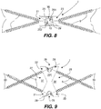
- Figure 8 should be viewed, where the screws 5 housed in the seats extend along the central longitudinal axes 30 of the self-same seats.
- the joint member 1 is usable for joining, that is to say, for mechanically connecting, a first panel 51 and a second panel 52 to each other.
- the first panel 51 and the second panel 52 are positioned side by side, so that a side or edge 511 of the first panel 51 is alongside a side or edge 521 of the second panel 52.
- a thin face of the first panel 51 (that is to say, the face substantially corresponding to the thickness of the panel and which connects the two opposite main faces) is facing towards a thin face of the second panel 52. If the panels have the same thickness, the main faces of one panel are substantially a continuation of the main faces of the other panel.
- the joint member 1 is positioned in a position interposed between the first panel 51 and the second panel 52 (in particular between their sides or edges 511, 521) in the joint region 50.
- the connecting portions 21, 22, that is to say, the connecting portions of the first pair, are fixed to the first panel 51 by means of respective fixing elements 5 in the seats 31, 32;
- the connecting portions 23, 24, that is to say, the connecting portions of the second pair, are fixed to the second panel 52 by means of respective fixing elements 5 in the seats 33, 34.
- an assembly 57 comprising the panels 51, 52, one or more joint members 1 and a plurality of fixing elements 5.
- FIG. 10 to 16 show a joint between the panels 51, 52 which is produced with three joint members 1, spaced from each other and evenly distributed along the joint region 50.
- the side or edge 511 of the first panel 51 and the side or edge 521 of the second panel 52 have respective hollowed regions (that is to say, hollows or recesses 55) in the thickness of the self-same panel for receiving a corresponding part of the joint member 1 (that is to say, the corresponding connecting portions 21, 22, 23, 24).
- the panels 51, 52 to be drawn near each other so that the side or edge 511 of the first panel 51 is substantially adjacent to (or even in contact with) the side or edge 521 of the second panel 52, except in said hollowed regions 55 where the joint member 1 is located. Therefore, between the two panels 51, 52 there may be a substantial surface continuity, except at the hollowed regions 55.
- each hollowed region 55 opens both on the side or edge (that is to say, on said thin face), and on the two opposite faces (or main faces) of the panel. Moreover, the hollowed region 55 may be shaped to match the portion of joint member 1 received in it.
- the joint member 1 is positioned in the hollowed regions 55 in such a way that the first side 25 and the second side 26 of the body 20 are on opposite faces of the assembly 57, that is to say, on opposite faces of the panels joined.
- first side 25 and the seats 31, 33 are accessible from the side shown in Figures 10 to 13 , through the openings of the hollowed regions 55 on the face from that side; the second side 26 and the seats 32, 34 are accessible from the other side (which is hidden in those figures) through the openings of the hollow regions 55 on the face from that other side.
- the plane of said plan view of the joint member 1 ( Figure 4 ) is substantially orthogonal to said opposite faces of the assembly 57, that is to say, is substantially orthogonal to the plane of the sheet of Figure 12 .
- the parallel faces 201, 202 of the body 20 are substantially orthogonal to said opposite faces of the assembly 57.
- the width of the joint member 1 (measured between the sides 25, 26) is roughly equal to (or slightly less than) the thickness of the panels 51, 52 (measured between said opposite faces). Therefore, the joint member 1 occupies practically the whole thickness of the hollowed regions 55, but without projecting from the opposite faces of the assembly 57.
- the assembly 57 may comprise a third panel 53 and at least one other joint member 1, as shown in Figure 16 .
- the second panel 52 has a second side or edge 522 which is alongside a side or edge 531 of the third panel 53.
- the third panel 53 is connected to the second panel 52 by means of at least one other joint member 1, with methods completely similar to those already described.
- the second panel 52 is interposed between the first panel 51 and the third panel 53.
- the joint member 1 can be used in particular for multi-layered wood or laminated wood panels, in particular of the X-LAM or CLT (Cross Laminated Timber) type.
- a wall 58 for a building is formed by a plurality of panels (in particular wooden panels, more specifically multi-layered wood or laminated wood panels, such as X-LAM or CLT) which are connected to each other using joint members 1. That wall 58 therefore comprises at least one assembly 57.
- FIG. 16 One example of use, which corresponds to what is shown in Figure 16 , relates to a wall 58 for a building, in which the wall 58 is required to have an opening for a door or for a window.
- At least three panels 51, 52, 53 are used which, as described above, are joined to each other by means of joint members 1 in such a way that the second panel 52 is interposed between the first panel 51 and the third panel 53.
- the panels are selected with sizes such that the first side or edge 521 and the second side or edge 522 of the second panel 52 have a length which is less than the respective sides or edges 511, 531 of the first panel 51 and of the third panel 53, whereby there is an open region 59 between the first panel 51 and the third panel 53.
- the second panel 52 has a height which is less than the height of the panels 51, 53.
- the first panel 51 and the third panel 53 are the lateral uprights of the opening for a door or for a window, whilst the second panel 52 is a crosspiece or an architrave of the opening for a door or for a window.
- the opening for a door or for a window is at least one part of said open region 59 or itself corresponds to said open region 59.
- FIG. 17 to 24 Alternative embodiments of a joint member according to this invention are shown in Figures 17 to 24 . Only the differences compared with the first embodiment of Figures 2 to 9 are commented on herein, it being understood that all of the other features and methods of use described for the first embodiment are also similarly applicable for these alternative embodiments.
- the first faces 41 are curved instead of flat as in the first embodiment.
- each first face 41 has a convex surface which may be considered similar to a portion of a cylindrical surface. This embodiment may be useful because making hollows or recesses 55 in the sides of the panels 51, 52, with concave curved surfaces that are also shaped to match the connecting portions, may be easier than hollows with flat surfaces.
- the body 20 of the joint member has a central region 205 which is elongate, so that the connecting portions in each pair (that is to say, the connecting portions for the same panel) are further away from each other than in the first embodiment.
- the central region 205 has flat faces intended to be contained between the sides of the panels. This embodiment may be useful for thicker panels.
- the joint member is formed by two pieces 20a, 20b which are made separately and which, once fitted together, form the body 20.
- a first piece 20a comprises the first connecting portion 21 and the third connecting portion 23;
- a second piece 20b comprises the second connecting portion 22 and the fourth connecting portion 24.
- each piece 20a, 20b is one half of the body 20 of the embodiments previously described: the two halves correspond to the pieces which would be obtained by "cutting" the body 20 with a cutting plane which cuts the housings 37, 38 separating the connecting portions intended to be fixed to the same panel.
- the two pieces 20a, 20b are fitted together for example by means of a threaded bar 207 or a stud (or other connecting element) which allows the distance between the two pieces 20a, 20b to be set at a selected value. That is useful for adapting the size of the joint member to the thickness of the panels.
- the joint members according to the embodiment in Figure 22 have an adjustable length and therefore they can be used for panels which, on each occasion, have different thickness: compared with the other embodiments, it is not necessary to produce joint members which are different and which have specific dimensions for each panel thickness.
- the first face of each connecting portion has a stepped shape.
- the first faces of the connecting portions of the same pair between them form the housing which, in use, is intended to receive the region of the side or edge of the respective panel.
- the first faces 41 have a stepped shape: as shown in Figures 23 and 24 , in the plan view the profile of each first face 41 is a jagged line.
- the housings 37, 38 therefore have a faceted shape which has a plurality of edges. That may be useful for promoting an improved interlocking of the joint member in the respective recesses 55 (shaped to match the housings 37, 38), obtaining better earthquake resistance performance.
- the joint member according to this invention has so far been illustrated as usable for producing walls of a building, that is to say, for connecting panels which are substantially vertical.
- the joint member is also similarly usable for producing a floor, which is formed by panels (in particular wooden panels, more particularly multi-layered wood or laminated wood panels, such as X-LAM or CLT) which are horizontal, drawn near each other and connected by the joint members. Therefore, a floor which includes the joint members described herein is also subject matter of this invention. In order to produce a floor, which could require greater thickness than a wall, the joint members according to the embodiments of Figures 21 and 22 may be particularly advisable.
Landscapes
- Engineering & Computer Science (AREA)
- Architecture (AREA)
- General Engineering & Computer Science (AREA)
- Physics & Mathematics (AREA)
- Electromagnetism (AREA)
- Civil Engineering (AREA)
- Structural Engineering (AREA)
- Mechanical Engineering (AREA)
- Joining Of Building Structures In Genera (AREA)
- Finishing Walls (AREA)
Abstract
Description
- This invention relates in general to the sector of constructions and in particular the subject matter of this invention is a joint member for panels. One specific field of use of this invention is the building sector, in particular for wooden buildings.
- According to one method currently used, the walls of a wooden building are made using prefabricated panels, made of wood (for example multi-layered wood or X-LAM type laminated wood panels), which are installed by positioning them vertically and joining them to each other. Since the width of each panel is limited by the production and transportation needs involved and therefore the width of the panel is less than the desired width of the wall, each wall is formed by a plurality of panels alongside each other so as to obtain the desired width.
- The mechanical connections between the panels and the foundation base, and between the panels themselves, are made for example by means of metal brackets or plates to be fixed to the faces of the panels and by fixing screws with various inclinations according to requirements.
- In general there is the need for alternative solutions which allow the panels to be joined together effectively in structural terms and which, if possible, minimise the manpower necessary for assembling them during installation and the risk of assembling errors or imperfections.
- In particular, the prior art methods involve drawbacks regarding the assembling of wooden walls in which there must be an opening for a door or for a window. That opening is laterally delimited by two lateral panels, which act as uprights, and is delimited at the top by a panel which acts as a crosspiece or architrave and which is constrained to the two lateral panels. The lateral panels hold the upper panel spaced from the ground and discharge to the ground the load that the structures above apply on the upper panel.
- Therefore, the mechanical connection between the lateral panels and the upper panel is required to be strong, suitable for transferring loads and carefully made.
- One prior art method involves shaping the upper portion of the sides of the lateral panels in such a way as to create supports for the upper panel. Moreover, the upper panel is mechanically connected to the lateral panels by means of fixing screws inserted from above into holes made in the thickness of the panels and having an inclination of approximately 45° relative to the vertical direction. The screws fix the upper panel to the lateral panels. See
Figure 1A with regard to this. - At least in the case of an opening for a window, the opening is also delimited at the bottom by a lower panel which in turn is fixed to the lateral panels by means of screws inserted into holes made in the thickness of the panels, at approximately 45° relative to the vertical direction.
- One drawback of this prior art method is that the precision required in making holes for the fixing screws makes it difficult to prepare them in advance before assembling: indeed the holes affect both the lateral panel and the panel to be fixed and must precisely fit together in the panels during installation. Consequently, in order to avoid risks of lack of alignment during assembling, the holes are usually made during installation, after the upper panel has been positioned on the supports. Making the holes and positioning the screws require working from above, which may be very awkward for operators. Moreover, the holes are long holes which, starting from the top, must pass through the height of the upper panel, therefore particular care by the operators is required in order to make them correctly during installation. Furthermore, the lateral panel shaping to create supports and the upper panel shaping to match, which are operations to be performed at the factory, may be at risk of working errors which are difficult to correct during installation.
- In variants of the prior art method, the fixing screws may be positioned differently: for example they may be inserted not from above but obliquely from the faces of the panels, or from above but with a different angle. In place of the fixing screws described above, it is possible to produce different fixing using pierced flat plates to be fixed to the faces of the panels, straddling the face of one panel and the face of the other panel alongside it. It should be noticed that all of these prior art methods have the disadvantage that the obtained result greatly depends on the professional expertise of the operators and on the precision of their assembling work during installation. For example, holes made with incorrect inclinations or in unsuitable positions may make the connection by fixing screws much weaker than expected. Therefore, the result of an earthquake resistance test performed on a wall specially built in the factory with the due care is in no way representative of the effective earthquake resistance behaviour of a corresponding wall installed: if the operators have not been precise in their work, the wall installed might not be capable of withstanding an earthquake which, according to the design and testing, it should have been able to withstand.
- In this context, the technical purpose which forms the basis of this invention is to provide a joint member for panels which allows the panels to be mechanically connected to each other with methods which overcome the drawbacks of the prior art, or at least to provide a joint member for panels which offers an alternative solution to the currently known solutions.
- The technical purpose specified and the aims indicated are substantially achieved by a joint member for panels according to
claim 1. Particular embodiments of this invention are defined in the corresponding dependent claims. This invention also relates to an assembly (in particular a wall of a building, or a floor of a building) comprising panels which are connected to each other by joint members according to this invention. - According to one aspect of this invention, the joint member has a body equipped with at least four connecting portions (or fixing portions) each having a respective seat intended to receive a fixing element. In use, each seat represents a point at which the joint member is fixable to a panel and the respective connecting portion is a body part which is configured for receiving the fixing element and for mechanically operating in conjunction with the latter and with the panel. The seats are spaced from each other and, in a plan view of the joint member, are positioned at the vertices of a quadrilateral. The connecting portions are fixable in pairs to the respective panels: in use, the fixing member is positioned in a position interposed between the first panel and the second panel, in a joint region in which a side or edge of the first panel is alongside a side or edge of the second panel; two connecting portions are fixed to the first panel; the other two connecting portions are fixed to the second panel. The joint member is shaped in such a way that its seats for the fixing elements are located, in pairs, on opposite sides of its body and those sides are located on opposite faces of the assembly formed by the panels which are alongside each other. That is useful for facilitating assembling operations: the sides of the joint member remain accessible when the latter is positioned between the panels and therefore the operator can easily position the fixing elements in the seats, if necessary also making the corresponding holes in the panels.
- It should be noticed that these operations can be performed by acting on the opposite faces of the assembly, for example on the vertical faces of the wall, not from above as in the prior art. This is easier for the operator.
- Moreover, the holes to be made during installation have a limited depth, determined by the length (variable according to requirements) of the fixing element to be received. They do not extend at all from the top of the upper panel and for a significant stretch of its height, as in contrast is necessary for the prior art shown in
Figure 1A . This greatly simplifies the operations to be performed during installation. - Furthermore, unlike the prior art mentioned above, the lateral panel shaping to create the supports and the upper panel shaping to match can be completely avoided: indeed the joint member is usable for joining panels with straight sides.
- In particular, in the sides or edges of the panels hollows or recesses can be made, in the thickness of the respective panel, for receiving a corresponding part of the joint member. The joint member may be completely housed in those hollows, without projecting from the faces of the assembly and without constituting a thickness between the sides or edges.
- The hollows or recesses can be easily made by milling and in particular can be made in the factory, thereby minimising the operations to be performed during installation.
- It should be noticed that the simplification of the operations to be performed during installation greatly reduces both the possibility of errors by the operators, and the influence of their professional expertise and precision on the obtained result. The risk of difference between the wall installed and the design specifications is much reduced. Therefore, the use of a joint member according to this invention is useful for ensuring that the wall installed has, in structural and earthquake resistance terms, characteristics which are reproducible and corresponding to those of the design. This allows to disengage the obtained result as far as possible from the margin of uncertainty due to the work of the operators who assembled the wall during installation.
- It should be noticed that what has been described and commented on with reference to a wall also applies with reference to a floor.
- In some embodiments in which the connecting portions intended for the same panel between them form a housing, it is possible to obtain substantial interlocking between the joint member and the panels, by suitably sizing and shaping the joint member and the hollows. That makes the connection even more secure and stronger, in addition to what can be obtained by the fixing elements, and may allow considerable earthquake resistance performance.
- One specific field of use of the joint member according to this invention is that of wooden structures, in which the joint member is usable for multi-layered wood or laminated wood panels, in particular of the X-LAM or CLT (Cross Laminated Timber) type.
- In this field, particular advantage may be gained from an embodiment of the joint member in which, for each pair of connecting portions which are fixable to the same panel, the seats for the fixing elements have central longitudinal axes which are slanting [not in the same plane] relative to each other and have projections which, in a view orthogonal to the plan view of the joint member, diverge in the direction coming out of the faces which face the same panel.
- Indeed, compared to configurations with fixing elements which are substantially coplanar, thanks to this configuration the fixing elements inserted into the panel affect a greater volume of the panel, they involve a greater number of fibres of the wood and they more effectively distribute the stresses in a more extensive zone of the panel. Therefore, a very strong joint is obtained.
- However, it should be noticed that the joint member according to this invention may be used for panels of any type and made of any material, not necessarily in the building sector.
- Further features and the advantages of this invention are more apparent in the following detailed description of several preferred, non-limiting embodiments of joint members for panels and of their use. Reference will be made to the accompanying drawings, in which:
-
Figure 1A shows, in a front view, the making of a wooden wall according to the prior art; -
Figures 1B and 1C respectively show a front view and a perspective view of a variant for making a wooden wall according to the prior art; -
Figure 2 shows a perspective view of a first embodiment of a joint member according to this invention; -
Figure 3 shows a view of one side of the joint member ofFigure 2 ; -
Figure 4 shows a plan view of the joint member ofFigure 2 ; -
Figure 5 shows a side view of the joint member ofFigure 2 ; -
Figure 6 shows a perspective view of the joint member ofFigure 2 , equipped with fixing elements; -
Figure 7 shows a side view of the joint member ofFigure 2 , equipped with fixing elements; -
Figure 8 shows a view of one side of the joint member ofFigure 2 , equipped with fixing elements; -
Figure 9 shows a plan view of the joint member ofFigure 2 , equipped with fixing elements; -
Figure 10 shows a perspective view of an assembly comprising two panels connected by joint members ofFigure 2 ; -
Figure 11 shows an enlarged detail fromFigure 10 ; -
Figure 12 shows a front view of the assembly ofFigure 10 ; -
Figure 13 shows an enlarged detail fromFigure 12 ; -
Figure 14 shows a cross-sectional view of a portion of the assembly ofFigure 10 , in section along section line XIV - XIV inFigure 12 at a joint member still without fixing elements; -
Figure 15 shows a cross-sectional view of a portion of the assembly ofFigure 10 , in section along section line XV - XV inFigure 12 at a joint member equipped with fixing elements; -
Figure 16 shows a perspective view of an assembly comprising three panels connected by joint members according to this invention, wherein in particular that assembly is a wall with an opening for a door; -
Figure 17 shows a perspective view of a second embodiment of a joint member according to this invention; -
Figure 18 shows a view of one side of the joint member ofFigure 17 ; -
Figure 19 shows a plan view of the joint member ofFigure 17 ; -
Figure 20 shows a side view of the joint member ofFigure 17 ; -
Figure 21 shows a perspective view of a third embodiment of a joint - member according to this invention;
-
Figure 22 shows a perspective view of a fourth embodiment of a joint member according to this invention; -
Figure 23 shows a plan view of a fifth embodiment of a joint member according to this invention, equipped with fixing elements; -
Figure 24 shows a plan view of a sixth embodiment of a joint member according to this invention, equipped with fixing elements. - With the sole purpose of putting this invention into context relative to a prior art in the wooden buildings sector,
Figure 1A shows a known method for making a wall made of wooden panels in which an opening for a door or for a window is required. The wall inFigure 1A is shown during an assembling step. - Two
lateral panels upper panel 92 and if necessary onelower panel 94 delimit anopening 90 for a door or for a window. -
Supports 95 are obtained in the sides of thelateral panels upper panel 92 is rested laterally on thesupports 95. - The
upper panel 92 is constrained to thelateral panels screws 96 are inserted intoholes 97, made at approximately 45° relative to the vertical direction. Theholes 97 pass through the height of theupper panel 92 and penetrate the sides of thelateral panels holes 97 are made and thescrews 96 are inserted from above. Thescrews 96 inserted into the bottom of theholes 97 therefore connect theupper panel 92 to thelateral panels screws 96 ininclined holes 97 is also used for thelower panel 94. - Alternatively, the panels may be constrained to each other by means of pierced
flat plates 98. For example thelower panel 94 is constrained to thelateral panels flat plates 98, which are fixed with screws to the faces of the panels. Essentially, theflat plates 98 straddle the face of thepanel 94 and the face of the other panel alongside 91, 93, parallel to the faces themselves. - In variants of the prior art method, the fixing screws 96 may be positioned differently: for example they may be inserted not from above but obliquely relative to the faces of the panels, or they may be inserted from above but with a different inclination or a different position.
Figures 1B and 1C should be viewed with regard to this, since for illustrative purposes they show threescrews 96 with different directions of insertion: two will be inserted into holes which start from the face of theupper panel 92 or of thelateral panel 93, the other will be inserted into a hole which starts from the top of thelateral panel 93 rather than from the top of theupper panel 92 as inFigure 1A . - In
figures 1B and 1C thescrews 96 are used for theupper panel 92, which is also laterally resting onsupports 95 made in thelateral panels flat plates 98 are used for thelower panel 94. - A first embodiment of a joint member for panels according to this invention is shown in
Figures 2 to 9 , where the joint member is labelled with thereference number 1. Thejoint member 1 is intended to mechanically connect a first panel and a second panel to each other. Basically, thejoint member 1 is a structural connecting element, which is used for assembling a structure formed by panels and remains incorporated in the structure itself, constituting a joint which constrains the two panels to each other. - One method for use of the
joint member 1 is illustrated inFigures 10 to 16 , which show, by way of example, an assembly comprising panels joined to each other by means of joint members according to this invention. In those figures, a first panel is labelled with thereference number 51, a second panel is labelled with thereference number 52, a third panel is labelled with thereference number 53. -
Figure 16 shows a wall of wooden panels in which an opening for a door or for a window is present. The differences compared with the prior art shown inFigures 1A, 1B and 1C are immediately evident. - The
joint member 1 is intended to be positioned in a position interposed between thefirst panel 51 and thesecond panel 52, in ajoint region 50 in which a side or edge 511 of thefirst panel 51 is alongside a side or edge 521 of thesecond panel 52. - The
joint member 1 has stiffness and mechanical strength suitable for the purpose of keeping thepanels - Depending on requirements, the
joint member 1 may be made of suitable material such as multi-layered or laminated wood (in particular X-LAM or Cross Laminated Timber), metal, plastic or bioplastic material, composite material (for example carbon fibre). Thejoint member 1 may be made as a single piece or may be formed by multiple pieces which are joined to each other. - The
joint member 1 has a body 20 (which specifically is a rigid, substantially non-deformable body) equipped with at least four connectingportions respective seat screw 5. - The
seats joint member 1, are positioned at the vertices of a quadrilateral.Figure 4 shows that plan view, in which moreover a quadrilateral (in particular a rectangle) has been sketched: the vertices of the quadrilateral are at central points of said seats. - Overall, the
body 20 substantially has a prismatic shape, with two substantially flat parallel faces 201, 202 (which are parallel to the plane of said plan view). Thebody 20 has a height between the twoparallel faces portions parallel faces seats parallel faces - A first and a second of said connecting portions, labelled with the
reference numbers first part 27 of thebody 20 and are intended to be fixed to thefirst panel 51. A third and a fourth of said connecting portions, labelled with thereference numbers second part 28 of thebody 20 and are intended to be fixed to thesecond panel 52. In particular, each pair is formed by two connecting portions on a same part of thebody 20, on the opposite side to the other pair. - Each connecting
portion first face 41 which, in use, is facing therespective panel 51, 52 (that is to say, facing the panel to which the connecting portion is fixed) and asecond face 42 which is on an opposite side to thefirst face 41. - The
second face 42 of the first connectingportion 21 and thesecond face 42 of the third connectingportion 23 are on a samefirst side 25 of thebody 20 of thejoint member 1. Thesecond face 42 of the second connectingportion 22 and thesecond face 42 of the fourth connectingportion 24 are on a samesecond side 26 of thebody 20 of thejoint member 1. Thesecond side 26 is opposite to thefirst side 25, that is to say, is on an opposite side of thebody 20. - In other words: the first connecting
portion 21 and the third connectingportion 23 are on a same part of thebody 20 but are intended to be fixed to different panels; the second connectingportion 22 and the fourth connectingportion 24 are on a same part (opposite to that of the connectingportions 21, 23) of thebody 20 but are intended to be fixed to different panels. - Each
seat portion first face 41 and thesecond face 42. The through hole has a centrallongitudinal axis 30. In practice, the respective fixing element (in particular a screw 5) is insertable into the seat from the side on which thesecond face 42 is and, coming out of the seat on the side on which thefirst face 41 is, the fixing element engages with the respective panel. - In particular, the
seats body 20. More specifically, eachseat first face 41 in a position halfway up the height of thebody 20, that is to say, equidistant from the twoparallel faces - Depending on structural and assembling requirements: the through hole may be a smooth hole, into which the
screw 5 is simply insertable with substantially free sliding and therefore the transfer of the longitudinal forces between thejoint member 1 and thescrew 5 is only at the head of thescrew 5; as an alternative, the through hole may be a threaded hole, having a thread engageable by the thread of thescrew 5, therefore the transfer of longitudinal forces between thejoint member 1 and thescrew 5 is also along the whole thread of the threaded hole. The choice between one or the other solution may also depend on the forces in play, to which the assembly is subjected once installed, and on the material used to make thejoint member 1. - As will be made clearer below, in use the first faces 41 are facing towards the respective panels and are hidden by the latter, whilst the second faces 42 remain free and accessible for an operator who is assembling the assembly (or structure) comprising the panels. Therefore the operator, acting from the
first side 25 and from thesecond side 26 of thebody 20, can position the fixingelements 5 in therespective seats elements 5, fix thejoint member 1 to thefirst panel 51 and to thesecond panel 52. - In the embodiments illustrated, with reference to the
first side 25 and to thesecond side 26 of thebody 20, the second faces 42 of the connecting portions on the same side form a cavity between them: afirst cavity 35 is present between the second faces 42 of the first connectingportion 21 and of the third connectingportion 23; asecond cavity 36 is present between the second faces 42 of the second connectingportion 22 and of the fourth connectingportion 24. For example, as shown inFigures 2 to 9 , the second faces 42 of the connecting portions on the same side are at least partly facing towards each other: they are inclined relative to each other and form an angle between them in the plan view (seeFigure 4 ). - The
seats cavities edges first panel 51 and of thesecond panel 52. The heads of the fixingelements 5 may remain housed in thosecavities respective side body 20. - For each connecting portion, an extension of the central
longitudinal axis 30 of the respective seat beyond thesecond face 42 does not intersect the other connecting portion on thesame side element 5 into the seat or during use of a tool such as a drill for making a corresponding hole in the panel or a screwdriver or a screwer for screwing the fixingelement 5 into the seat and into the panel. - Said feature is obtainable with a suitable shape of the connecting portions, for example by suitably selecting the position of the seats, the inclination of their longitudinal axis and the relative inclination between the second faces of the connecting portions.
- In the embodiment illustrated, said feature is also obtained with the following device: the other connecting portion on the
same side longitudinal axis 30 travels or passes. In practice, the extension of the centrallongitudinal axis 30 meets and travels through that hollow 29 (corresponding to an absence of material) rather than through the material which constitutes thebody 20. As regards the first pair and the second pair of connecting portions, in the embodiment illustrated the first faces 41 of the connecting portions of the same pair between them form a housing which, in use, is intended to receive a region of the side or edge of the respective panel: afirst housing 37 is present between the first faces 41 of the first connectingportion 21 and of the second connectingportion 22 and is intended to receive a region of the side or edge 511 of thefirst panel 51; asecond housing 38 is present between the first faces 41 of the third connectingportion 23 and of the fourth connectingportion 24 and is intended to receive a region of the side or edge 521 of thesecond panel 52. In practice, each pair forms a sort of fork. - For example, as shown in
Figures 2 to 9 and similarly to what is described above for thecavities Figure 4 ). - In the embodiment illustrated, the
sides panels joint member 1. In particular, each hollow orrecess 55 has a region with a shape that substantially matches therespective housing Figure 10 in combination withFigure 4 . - That is useful for increasing the contact surface area and the strength of the constraint between the panel and the
joint member 1, thereby producing a more secure and stronger connection. - As can be seen in the figures for the embodiments illustrated, the connecting
portions body 20 of thejoint member 1. In particular, the connecting portions are in a radial arrangement. - In the plan view, as shown in
Figure 4 , thejoint member 1 substantially has the shape of an X or a cross, where the connecting portions form the arms of that shape. In other words, the twoparallel faces body 20 have that shape. - An X or cross shape appears to be advantageous both as regards the use of the joint member 1 (see what has already been mentioned above in relation to the
cavities housings 37, 38), and as regards production of thejoint member 1 itself, since this allows the consumption of material and the weight of thejoint member 1 obtained to be limited. - For the first pair and the second pair of connecting portions, in said plan view the projections of the central
longitudinal axes 30 of the seats of the connecting portions of the same pair converge in the direction coming out of the first faces 41, that is to say, they converge with each other towards the respective panel. With regard to this, in addition toFigure 4 ,Figure 9 should also be viewed, where thescrews 5 housed in the seats extend along the centrallongitudinal axes 30 of the self-same seats. In practice, thescrews 5 which fix thejoint member 1 to a panel are not parallel to each other and they converge, engaging oblique stretches of the thickness of the panel. That is useful for achieving a satisfactory distribution of the longitudinal and shearing stresses and of the twisting moments acting on the joint. Moreover, the insertion of thescrews 5 into the seats is easy thanks to the inclination of the centrallongitudinal axes 30 beyond the second faces 42. - Moreover, again for the first pair and the second pair of connecting portions, the central
longitudinal axes 30 of the seats of the connecting portions of the same pair are slanting [not in the same plane] relative to each other and have projections which, in a view orthogonal to said plan view, diverge in the direction coming out of the first faces 41, that is to say, they diverge towards the respective panel. - With regard to this,
Figure 8 should be viewed, where thescrews 5 housed in the seats extend along the centrallongitudinal axes 30 of the self-same seats. - This is useful, on one hand, for improving the resistance of the joint to longitudinal and shearing stresses and to twisting moments, and on the other hand for preventing the two
screws 5 from being able to interfere with each other if they converge in plan view (as described above). - One method for use of the
joint member 1 is described below. - The
joint member 1 is usable for joining, that is to say, for mechanically connecting, afirst panel 51 and asecond panel 52 to each other. - The
first panel 51 and thesecond panel 52 are positioned side by side, so that a side or edge 511 of thefirst panel 51 is alongside a side or edge 521 of thesecond panel 52. In practice, a thin face of the first panel 51 (that is to say, the face substantially corresponding to the thickness of the panel and which connects the two opposite main faces) is facing towards a thin face of thesecond panel 52. If the panels have the same thickness, the main faces of one panel are substantially a continuation of the main faces of the other panel. - The
joint member 1 is positioned in a position interposed between thefirst panel 51 and the second panel 52 (in particular between their sides oredges 511, 521) in thejoint region 50. - The connecting
portions first panel 51 by means ofrespective fixing elements 5 in theseats portions second panel 52 by means ofrespective fixing elements 5 in theseats - Therefore, an
assembly 57 is obtained, comprising thepanels joint members 1 and a plurality of fixingelements 5. - In particular, in order to join the two
panels joint members 1, which are positioned one after another along the sides oredges Figures 10 to 16 for example show a joint between thepanels joint members 1, spaced from each other and evenly distributed along thejoint region 50. As already indicated above, in the embodiment illustrated the side or edge 511 of thefirst panel 51 and the side or edge 521 of thesecond panel 52 have respective hollowed regions (that is to say, hollows or recesses 55) in the thickness of the self-same panel for receiving a corresponding part of the joint member 1 (that is to say, the corresponding connectingportions - That allows the
panels first panel 51 is substantially adjacent to (or even in contact with) the side or edge 521 of thesecond panel 52, except in saidhollowed regions 55 where thejoint member 1 is located. Therefore, between the twopanels regions 55. - It should be noticed that each
hollowed region 55 opens both on the side or edge (that is to say, on said thin face), and on the two opposite faces (or main faces) of the panel. Moreover, the hollowedregion 55 may be shaped to match the portion ofjoint member 1 received in it. - The
joint member 1 is positioned in the hollowedregions 55 in such a way that thefirst side 25 and thesecond side 26 of thebody 20 are on opposite faces of theassembly 57, that is to say, on opposite faces of the panels joined. - Therefore, the
first side 25 and theseats Figures 10 to 13 , through the openings of the hollowedregions 55 on the face from that side; thesecond side 26 and theseats hollow regions 55 on the face from that other side. - The plane of said plan view of the joint member 1 (
Figure 4 ) is substantially orthogonal to said opposite faces of theassembly 57, that is to say, is substantially orthogonal to the plane of the sheet ofFigure 12 . In particular, the parallel faces 201, 202 of thebody 20 are substantially orthogonal to said opposite faces of theassembly 57. - The width of the joint member 1 (measured between the
sides 25, 26) is roughly equal to (or slightly less than) the thickness of thepanels 51, 52 (measured between said opposite faces). Therefore, thejoint member 1 occupies practically the whole thickness of the hollowedregions 55, but without projecting from the opposite faces of theassembly 57. - Using a suitable number of
joint members 1 it is possible to connect multiple panels to each other. For example theassembly 57 may comprise athird panel 53 and at least one otherjoint member 1, as shown inFigure 16 . - In addition to the first side or edge 521 to which the
first panel 51 is connected, thesecond panel 52 has a second side or edge 522 which is alongside a side or edge 531 of thethird panel 53. Thethird panel 53 is connected to thesecond panel 52 by means of at least one otherjoint member 1, with methods completely similar to those already described. Thesecond panel 52 is interposed between thefirst panel 51 and thethird panel 53. - The
joint member 1 can be used in particular for multi-layered wood or laminated wood panels, in particular of the X-LAM or CLT (Cross Laminated Timber) type. - One specific field of use is the construction of buildings which have wooden walls and/or wooden floors. For example, a
wall 58 for a building is formed by a plurality of panels (in particular wooden panels, more specifically multi-layered wood or laminated wood panels, such as X-LAM or CLT) which are connected to each other usingjoint members 1. Thatwall 58 therefore comprises at least oneassembly 57. - One example of use, which corresponds to what is shown in
Figure 16 , relates to awall 58 for a building, in which thewall 58 is required to have an opening for a door or for a window. - For this purpose at least three
panels joint members 1 in such a way that thesecond panel 52 is interposed between thefirst panel 51 and thethird panel 53. - The panels are selected with sizes such that the first side or
edge 521 and the second side or edge 522 of thesecond panel 52 have a length which is less than the respective sides oredges first panel 51 and of thethird panel 53, whereby there is anopen region 59 between thefirst panel 51 and thethird panel 53. In other words, thesecond panel 52 has a height which is less than the height of thepanels - Once installed, the
first panel 51 and thethird panel 53 are the lateral uprights of the opening for a door or for a window, whilst thesecond panel 52 is a crosspiece or an architrave of the opening for a door or for a window. In practice, the opening for a door or for a window is at least one part of saidopen region 59 or itself corresponds to saidopen region 59. - Alternative embodiments of a joint member according to this invention are shown in
Figures 17 to 24 . Only the differences compared with the first embodiment ofFigures 2 to 9 are commented on herein, it being understood that all of the other features and methods of use described for the first embodiment are also similarly applicable for these alternative embodiments. In the embodiment ofFigures 17 to 20 , the first faces 41 are curved instead of flat as in the first embodiment. In particular, eachfirst face 41 has a convex surface which may be considered similar to a portion of a cylindrical surface. This embodiment may be useful because making hollows or recesses 55 in the sides of thepanels - In the embodiment in
Figure 21 , thebody 20 of the joint member has acentral region 205 which is elongate, so that the connecting portions in each pair (that is to say, the connecting portions for the same panel) are further away from each other than in the first embodiment. Moreover thecentral region 205 has flat faces intended to be contained between the sides of the panels. This embodiment may be useful for thicker panels. - In the embodiment in
Figure 22 , the joint member is formed by twopieces body 20. Afirst piece 20a comprises the first connectingportion 21 and the third connectingportion 23; asecond piece 20b comprises the second connectingportion 22 and the fourth connectingportion 24. - Essentially, each
piece body 20 of the embodiments previously described: the two halves correspond to the pieces which would be obtained by "cutting" thebody 20 with a cutting plane which cuts thehousings - The two
pieces bar 207 or a stud (or other connecting element) which allows the distance between the twopieces Figure 22 have an adjustable length and therefore they can be used for panels which, on each occasion, have different thickness: compared with the other embodiments, it is not necessary to produce joint members which are different and which have specific dimensions for each panel thickness. - In particular embodiments of a joint member according to this invention, the first face of each connecting portion has a stepped shape. The first faces of the connecting portions of the same pair between them form the housing which, in use, is intended to receive the region of the side or edge of the respective panel.
- Examples of those particular embodiments are the embodiments in
Figures 23 and 24 , which are only shown in plan view and equipped with fixingscrews 5. The first faces 41 have a stepped shape: as shown inFigures 23 and 24 , in the plan view the profile of eachfirst face 41 is a jagged line. Thehousings housings 37, 38), obtaining better earthquake resistance performance. - Obviously, the differentiating aspects of each embodiment may be combined with each other to obtain other embodiments.
- The joint member according to this invention has so far been illustrated as usable for producing walls of a building, that is to say, for connecting panels which are substantially vertical.
- The joint member is also similarly usable for producing a floor, which is formed by panels (in particular wooden panels, more particularly multi-layered wood or laminated wood panels, such as X-LAM or CLT) which are horizontal, drawn near each other and connected by the joint members. Therefore, a floor which includes the joint members described herein is also subject matter of this invention. In order to produce a floor, which could require greater thickness than a wall, the joint members according to the embodiments of
Figures 21 and 22 may be particularly advisable. - The invention described above may be modified and adapted in several ways without thereby departing from the scope of the appended claims.
- All details may be substituted with other technically equivalent elements and the materials used, as well as the shapes and dimensions of the various components, may vary according to requirements.
Claims (15)
- A joint member (1) for panels,the joint member (1) being intended to mechanically connect a first panel (51) and a second panel (52) to each other,the joint member (1) being intended to be positioned in a position interposed between the first panel (51) and the second panel (52), in a joint region in which a side or edge (511) of the first panel (51) is alongside a side or edge (521) of the second panel (52),the joint member (1) having a body (20) equipped with at least four connecting portions (21, 22, 23, 24) each having a respective seat (31, 32, 33, 34) intended to receive a fixing element (5), the seats (31, 32, 33, 34) being spaced from each other and, in a plan view of the joint member (1), being positioned at the vertices of a quadrilateral,wherein a first (21) and a second (22) of said connecting portions form a first pair of connecting portions and are intended to be fixed to the first panel (51), and wherein a third (23) and a fourth (24) of said connecting portions form a second pair of connecting portions and are intended to be fixed to the second panel (52),each connecting portion (21, 22, 23, 24) having a first face (41) which, in use, is facing the respective panel (51, 52), and a second face (42) which is on an opposite side to the first face (41), said respective seat (31, 32, 33, 34) being, or comprising, a through hole which extends in a thickness of the connecting portion (21, 22, 23, 24) between the first face (41) and the second face (42) and which has a central longitudinal axis (30),the second face (42) of the first connecting portion (21) and the second face (42) of the third connecting portion (23) being on a same first side (25) of the body (20), the second face (42) of the second connecting portion (22) and the second face (42) of the fourth connecting portion (24) being on a same second side (26) of the body (20), opposite to the first side (25).
- The joint member (1) according to claim 1, wherein, for the first pair (21, 22) and the second pair (23, 24) of connecting portions, the central longitudinal axes (30) of the seats (31, 32, 33, 34) of the connecting portions of the same pair are slanting [not in the same plane] relative to each other and have projections which, in a view orthogonal to said plan view, diverge in the direction coming out of the first faces (41).
- The joint member (1) according to claim 2, wherein, for the first pair (21, 22) and the second pair (23, 24) of connecting portions, in said plan view the projections of the central longitudinal axes (30) of the seats (31, 32, 33, 34) of the connecting portions of the same pair converge in the direction coming out of the first faces (41).
- The joint member (1) according to any of claims 1 to 3, wherein, for the first pair (21, 22) and the second pair (23, 24) of connecting portions, the first faces (41) of the connecting portions of the same pair between them form a housing (37, 38) which, in use, is intended to receive a region of the side or edge (511, 521) of the respective panel (51, 52).
- The joint member (1) according to any of claims 1 to 4, wherein, for the first side (25) and the second side (26) of the body (20), the second faces (42) of the connecting portions on the same side between them form a cavity (35, 36).
- The joint member (1) according to claim 5, wherein, for each connecting portion (21, 22, 23, 24), an extension of the central longitudinal axis (30) of the seat (31, 32, 33, 34) beyond the second face (42) does not intersect the other connecting portion on the same side (25, 26), and
wherein the other connecting portion on the same side (25, 26) has a hollow or a hole (29) through which said extension of the central longitudinal axis (30) passes. - The joint member (1) according to any of claims 1 to 6, wherein said connecting portions (21, 22, 23, 24) are wings or arms which extend from a central region of the body (20), in particular wherein, in said plan view of the joint member (1), the joint member (1) substantially has the shape of an X or a cross.
- An assembly (57) comprising a first panel (51), a second panel (52), at least one joint member (1) according to any of claims 1 to 7, a plurality of fixing elements (5),wherein a side or edge (511) of the first panel (51) is alongside a side or edge (521) of the second panel (52), the joint member (1) is in a position interposed between the first panel (51) and the second panel (52) in a respective joint region,the connecting portions (21, 22) of the first pair being fixed to the first panel (51) by means of respective fixing elements (5) in their seats (31, 32), the connecting portions (23, 24) of the second pair being fixed to the second panel (52) by means of respective fixing elements (5) in their seats (33, 34).
- The assembly (57) according to claim 8, wherein the side or edge (511) of the first panel (51) and the side or edge (521) of the second panel (52) have respective hollows or recesses (55) made in the thickness of the panel (51, 52) for receiving a corresponding part of the joint member (1), so that the side or edge (511) of the first panel (51) is substantially adjacent to the side or edge (521) of the second panel (52) except at said hollows or recesses (55).
- The assembly (57) according to claim 8 or 9, wherein the first side (25) of the body (20) of the joint member (1) and the second side (26) of the body (20) of the joint member (1) are on opposite faces of the assembly (57), and wherein the plane of said plan view of the joint member (1) is substantially orthogonal to said opposite faces.
- The assembly (57) according to any of claims 8 to 10, comprising a plurality of joint members (1) according to any of claims 1 to 7, the joint members (1) being positioned one after another along the sides or edges (511, 521) of the panels (51, 52), each joint member (1) being in a position interposed between the first panel (51) and the second panel (52) and being fixed to the panels (51, 52) by means of respective fixing elements (5).
- The assembly (57) according to any of claims 8 to 11, wherein the first panel (51) and the second panel (52) are multi-layered wood or laminated wood panels, in particular of the X-LAM or CLT (Cross Laminated Timber) type.
- The assembly (57) according to any of claims 8 to 12, comprising a third panel (53) and at least one other joint member (1) according to any of claims 1 to 7,wherein the second panel (52) has a first side or edge (521) and a second side or edge (522) which is opposite to the first side or edge (521),the first side or edge (521) of the second panel (52) being alongside the side or edge (511) of the first panel (51), the second side or edge (522) of the second panel (52) being alongside a side or edge (531) of the third panel (53), the third panel (53) being connected to the second panel (52) by means of said at least one other joint member (1),the second panel (52) being interposed between the first panel (51) and the third panel (53).
- A wall (58) for a building or a floor for a building, formed by a plurality of panels (51, 52, 53) and comprising at least one assembly (57) according to any of claims 8 to 13.
- A wall (58) for a building, formed by a plurality of panels (51, 52, 53) and comprising at least one assembly (57) according to claim 13, wherein the first side or edge (521) and the second side or edge (522) of the second panel (52) have a length which is less than the respective sides or edges (511, 531) of the first panel (51) and of the third panel (53), whereby there is an open region (59) between the first panel (51) and the third panel (53), the first panel (51) and the third panel (53) being lateral uprights of an opening for a door or for a window, the second panel (52) being a crosspiece or an architrave of said opening for a door or for a window, said opening for a door or for a window being at least one part of said open region (59).
Applications Claiming Priority (1)
| Application Number | Priority Date | Filing Date | Title |
|---|---|---|---|
| IT102019000004815A IT201900004815A1 (en) | 2019-03-29 | 2019-03-29 | JOINT MEMBER FOR PANELS |
Publications (2)
| Publication Number | Publication Date |
|---|---|
| EP3715549A1 true EP3715549A1 (en) | 2020-09-30 |
| EP3715549B1 EP3715549B1 (en) | 2022-07-13 |
Family
ID=67185600
Family Applications (1)
| Application Number | Title | Priority Date | Filing Date |
|---|---|---|---|
| EP20166013.1A Active EP3715549B1 (en) | 2019-03-29 | 2020-03-26 | Joint member for panels |
Country Status (3)
| Country | Link |
|---|---|
| EP (1) | EP3715549B1 (en) |
| ES (1) | ES2928414T3 (en) |
| IT (1) | IT201900004815A1 (en) |
Cited By (1)
| Publication number | Priority date | Publication date | Assignee | Title |
|---|---|---|---|---|
| EP4733503A1 (en) * | 2024-10-22 | 2026-04-29 | Adolf Würth GmbH & Co. KG | Assembly, use, building and method for erecting a building |
Citations (4)
| Publication number | Priority date | Publication date | Assignee | Title |
|---|---|---|---|---|
| EP0072139A1 (en) * | 1981-08-10 | 1983-02-16 | Ensphere Concept International Inc. | A connector for a structural member |
| KR20030006886A (en) * | 2001-10-15 | 2003-01-23 | 경민산업주식회사 | model of structure and method of erection for traditional wooden structure with glued laminated timber and steel connecter |
| US20150368915A1 (en) * | 2013-02-05 | 2015-12-24 | Yessform Co., Ltd. | Form board and method of constructing form using the same |
| JP2019011631A (en) * | 2017-06-30 | 2019-01-24 | 木構造システム株式会社 | Sitting tool, wood member joining structure using the same, and wood member joining method |
-
2019
- 2019-03-29 IT IT102019000004815A patent/IT201900004815A1/en unknown
-
2020
- 2020-03-26 EP EP20166013.1A patent/EP3715549B1/en active Active
- 2020-03-26 ES ES20166013T patent/ES2928414T3/en active Active
Patent Citations (4)
| Publication number | Priority date | Publication date | Assignee | Title |
|---|---|---|---|---|
| EP0072139A1 (en) * | 1981-08-10 | 1983-02-16 | Ensphere Concept International Inc. | A connector for a structural member |
| KR20030006886A (en) * | 2001-10-15 | 2003-01-23 | 경민산업주식회사 | model of structure and method of erection for traditional wooden structure with glued laminated timber and steel connecter |
| US20150368915A1 (en) * | 2013-02-05 | 2015-12-24 | Yessform Co., Ltd. | Form board and method of constructing form using the same |
| JP2019011631A (en) * | 2017-06-30 | 2019-01-24 | 木構造システム株式会社 | Sitting tool, wood member joining structure using the same, and wood member joining method |
Cited By (1)
| Publication number | Priority date | Publication date | Assignee | Title |
|---|---|---|---|---|
| EP4733503A1 (en) * | 2024-10-22 | 2026-04-29 | Adolf Würth GmbH & Co. KG | Assembly, use, building and method for erecting a building |
Also Published As
| Publication number | Publication date |
|---|---|
| ES2928414T3 (en) | 2022-11-17 |
| IT201900004815A1 (en) | 2020-09-29 |
| EP3715549B1 (en) | 2022-07-13 |
Similar Documents
| Publication | Publication Date | Title |
|---|---|---|
| KR101932560B1 (en) | Mechanically interlocking frame assemblies | |
| US20080213040A1 (en) | Shear Connector for Connecting at Least Two Components and System of Interconnected Components | |
| US9238909B2 (en) | Column base joint structure | |
| JP3272839B2 (en) | Jig for joining | |
| CA3015924A1 (en) | Method and connector set for connecting beams of wood material | |
| US11221031B1 (en) | Joint member for panels | |
| EP3715549A1 (en) | Joint member for panels | |
| KR102101193B1 (en) | Modular unit having connection block and modular unit structure using the same | |
| CA3096179A1 (en) | Joint member for panels | |
| AU2020256441A1 (en) | Joint member for panels | |
| EP2345768A1 (en) | Interlocking structural reinforcement system | |
| JP5542117B2 (en) | Connector | |
| JP3172859U (en) | Plastic formwork structure | |
| JP3670984B2 (en) | Wooden building assembly structure and method for assembling the same | |
| US11274436B2 (en) | Method for producing a construction of interconnected wooden panels | |
| KR102195114B1 (en) | Method locking firmly steel structure joining the joint of timber column and beam | |
| JP6808196B2 (en) | Connected structure | |
| KR20100046666A (en) | Fabricated grillage connector for column head in wooden structure | |
| JP2725165B2 (en) | Joining structure of wooden building horizontal members and its tools | |
| JP2681620B2 (en) | Joining structure of wooden building horizontal members and its tools | |
| JP2006177108A (en) | Material fixture | |
| JP7062463B2 (en) | Connection structure | |
| JPH09125530A (en) | Connection structure of horizontal member in wooden building | |
| CN222349930U (en) | A flowering column connection node | |
| KR200182227Y1 (en) | Steel connector for wooden structure. |
Legal Events
| Date | Code | Title | Description |
|---|---|---|---|
| PUAI | Public reference made under article 153(3) epc to a published international application that has entered the european phase |
Free format text: ORIGINAL CODE: 0009012 |
|
| STAA | Information on the status of an ep patent application or granted ep patent |
Free format text: STATUS: THE APPLICATION HAS BEEN PUBLISHED |
|
| AK | Designated contracting states |
Kind code of ref document: A1 Designated state(s): AL AT BE BG CH CY CZ DE DK EE ES FI FR GB GR HR HU IE IS IT LI LT LU LV MC MK MT NL NO PL PT RO RS SE SI SK SM TR |
|
| AX | Request for extension of the european patent |
Extension state: BA ME |
|
| STAA | Information on the status of an ep patent application or granted ep patent |
Free format text: STATUS: REQUEST FOR EXAMINATION WAS MADE |
|
| STAA | Information on the status of an ep patent application or granted ep patent |
Free format text: STATUS: EXAMINATION IS IN PROGRESS |
|
| 17P | Request for examination filed |
Effective date: 20210324 |
|
| RBV | Designated contracting states (corrected) |
Designated state(s): AL AT BE BG CH CY CZ DE DK EE ES FI FR GB GR HR HU IE IS IT LI LT LU LV MC MK MT NL NO PL PT RO RS SE SI SK SM TR |
|
| 17Q | First examination report despatched |
Effective date: 20210412 |
|
| GRAP | Despatch of communication of intention to grant a patent |
Free format text: ORIGINAL CODE: EPIDOSNIGR1 |
|
| STAA | Information on the status of an ep patent application or granted ep patent |
Free format text: STATUS: GRANT OF PATENT IS INTENDED |
|
| RIC1 | Information provided on ipc code assigned before grant |
Ipc: F16B 5/00 20060101ALN20211216BHEP Ipc: E04B 1/10 20060101ALN20211216BHEP Ipc: E04B 1/61 20060101AFI20211216BHEP |
|
| INTG | Intention to grant announced |
Effective date: 20220107 |
|
| GRAS | Grant fee paid |
Free format text: ORIGINAL CODE: EPIDOSNIGR3 |
|
| GRAA | (expected) grant |
Free format text: ORIGINAL CODE: 0009210 |
|
| STAA | Information on the status of an ep patent application or granted ep patent |
Free format text: STATUS: THE PATENT HAS BEEN GRANTED |
|
| AK | Designated contracting states |
Kind code of ref document: B1 Designated state(s): AL AT BE BG CH CY CZ DE DK EE ES FI FR GB GR HR HU IE IS IT LI LT LU LV MC MK MT NL NO PL PT RO RS SE SI SK SM TR |
|
| REG | Reference to a national code |
Ref country code: CH Ref legal event code: EP |
|
| REG | Reference to a national code |
Ref country code: DE Ref legal event code: R096 Ref document number: 602020003948 Country of ref document: DE |
|
| REG | Reference to a national code |
Ref country code: AT Ref legal event code: REF Ref document number: 1504368 Country of ref document: AT Kind code of ref document: T Effective date: 20220815 |
|
| REG | Reference to a national code |
Ref country code: IE Ref legal event code: FG4D |
|
| REG | Reference to a national code |
Ref country code: LT Ref legal event code: MG9D |
|
| REG | Reference to a national code |
Ref country code: NL Ref legal event code: MP Effective date: 20220713 |
|
| REG | Reference to a national code |
Ref country code: ES Ref legal event code: FG2A Ref document number: 2928414 Country of ref document: ES Kind code of ref document: T3 Effective date: 20221117 |
|
| PG25 | Lapsed in a contracting state [announced via postgrant information from national office to epo] |
Ref country code: SE Free format text: LAPSE BECAUSE OF FAILURE TO SUBMIT A TRANSLATION OF THE DESCRIPTION OR TO PAY THE FEE WITHIN THE PRESCRIBED TIME-LIMIT Effective date: 20220713 Ref country code: RS Free format text: LAPSE BECAUSE OF FAILURE TO SUBMIT A TRANSLATION OF THE DESCRIPTION OR TO PAY THE FEE WITHIN THE PRESCRIBED TIME-LIMIT Effective date: 20220713 Ref country code: PT Free format text: LAPSE BECAUSE OF FAILURE TO SUBMIT A TRANSLATION OF THE DESCRIPTION OR TO PAY THE FEE WITHIN THE PRESCRIBED TIME-LIMIT Effective date: 20221114 Ref country code: NO Free format text: LAPSE BECAUSE OF FAILURE TO SUBMIT A TRANSLATION OF THE DESCRIPTION OR TO PAY THE FEE WITHIN THE PRESCRIBED TIME-LIMIT Effective date: 20221013 Ref country code: NL Free format text: LAPSE BECAUSE OF FAILURE TO SUBMIT A TRANSLATION OF THE DESCRIPTION OR TO PAY THE FEE WITHIN THE PRESCRIBED TIME-LIMIT Effective date: 20220713 Ref country code: LV Free format text: LAPSE BECAUSE OF FAILURE TO SUBMIT A TRANSLATION OF THE DESCRIPTION OR TO PAY THE FEE WITHIN THE PRESCRIBED TIME-LIMIT Effective date: 20220713 Ref country code: LT Free format text: LAPSE BECAUSE OF FAILURE TO SUBMIT A TRANSLATION OF THE DESCRIPTION OR TO PAY THE FEE WITHIN THE PRESCRIBED TIME-LIMIT Effective date: 20220713 Ref country code: FI Free format text: LAPSE BECAUSE OF FAILURE TO SUBMIT A TRANSLATION OF THE DESCRIPTION OR TO PAY THE FEE WITHIN THE PRESCRIBED TIME-LIMIT Effective date: 20220713 |
|
| PG25 | Lapsed in a contracting state [announced via postgrant information from national office to epo] |
Ref country code: PL Free format text: LAPSE BECAUSE OF FAILURE TO SUBMIT A TRANSLATION OF THE DESCRIPTION OR TO PAY THE FEE WITHIN THE PRESCRIBED TIME-LIMIT Effective date: 20220713 Ref country code: IS Free format text: LAPSE BECAUSE OF FAILURE TO SUBMIT A TRANSLATION OF THE DESCRIPTION OR TO PAY THE FEE WITHIN THE PRESCRIBED TIME-LIMIT Effective date: 20221113 Ref country code: HR Free format text: LAPSE BECAUSE OF FAILURE TO SUBMIT A TRANSLATION OF THE DESCRIPTION OR TO PAY THE FEE WITHIN THE PRESCRIBED TIME-LIMIT Effective date: 20220713 Ref country code: GR Free format text: LAPSE BECAUSE OF FAILURE TO SUBMIT A TRANSLATION OF THE DESCRIPTION OR TO PAY THE FEE WITHIN THE PRESCRIBED TIME-LIMIT Effective date: 20221014 |
|
| REG | Reference to a national code |
Ref country code: DE Ref legal event code: R097 Ref document number: 602020003948 Country of ref document: DE |
|
| PG25 | Lapsed in a contracting state [announced via postgrant information from national office to epo] |
Ref country code: SM Free format text: LAPSE BECAUSE OF FAILURE TO SUBMIT A TRANSLATION OF THE DESCRIPTION OR TO PAY THE FEE WITHIN THE PRESCRIBED TIME-LIMIT Effective date: 20220713 Ref country code: RO Free format text: LAPSE BECAUSE OF FAILURE TO SUBMIT A TRANSLATION OF THE DESCRIPTION OR TO PAY THE FEE WITHIN THE PRESCRIBED TIME-LIMIT Effective date: 20220713 Ref country code: DK Free format text: LAPSE BECAUSE OF FAILURE TO SUBMIT A TRANSLATION OF THE DESCRIPTION OR TO PAY THE FEE WITHIN THE PRESCRIBED TIME-LIMIT Effective date: 20220713 Ref country code: CZ Free format text: LAPSE BECAUSE OF FAILURE TO SUBMIT A TRANSLATION OF THE DESCRIPTION OR TO PAY THE FEE WITHIN THE PRESCRIBED TIME-LIMIT Effective date: 20220713 |
|
| PLBE | No opposition filed within time limit |
Free format text: ORIGINAL CODE: 0009261 |
|
| STAA | Information on the status of an ep patent application or granted ep patent |
Free format text: STATUS: NO OPPOSITION FILED WITHIN TIME LIMIT |
|
| PG25 | Lapsed in a contracting state [announced via postgrant information from national office to epo] |
Ref country code: SK Free format text: LAPSE BECAUSE OF FAILURE TO SUBMIT A TRANSLATION OF THE DESCRIPTION OR TO PAY THE FEE WITHIN THE PRESCRIBED TIME-LIMIT Effective date: 20220713 Ref country code: EE Free format text: LAPSE BECAUSE OF FAILURE TO SUBMIT A TRANSLATION OF THE DESCRIPTION OR TO PAY THE FEE WITHIN THE PRESCRIBED TIME-LIMIT Effective date: 20220713 |
|
| P01 | Opt-out of the competence of the unified patent court (upc) registered |
Effective date: 20230502 |
|
| 26N | No opposition filed |
Effective date: 20230414 |
|
| PG25 | Lapsed in a contracting state [announced via postgrant information from national office to epo] |
Ref country code: AL Free format text: LAPSE BECAUSE OF FAILURE TO SUBMIT A TRANSLATION OF THE DESCRIPTION OR TO PAY THE FEE WITHIN THE PRESCRIBED TIME-LIMIT Effective date: 20220713 |
|
| PG25 | Lapsed in a contracting state [announced via postgrant information from national office to epo] |
Ref country code: SI Free format text: LAPSE BECAUSE OF FAILURE TO SUBMIT A TRANSLATION OF THE DESCRIPTION OR TO PAY THE FEE WITHIN THE PRESCRIBED TIME-LIMIT Effective date: 20220713 |
|
| PG25 | Lapsed in a contracting state [announced via postgrant information from national office to epo] |
Ref country code: MC Free format text: LAPSE BECAUSE OF FAILURE TO SUBMIT A TRANSLATION OF THE DESCRIPTION OR TO PAY THE FEE WITHIN THE PRESCRIBED TIME-LIMIT Effective date: 20220713 |
|
| REG | Reference to a national code |
Ref country code: AT Ref legal event code: UEP Ref document number: 1504368 Country of ref document: AT Kind code of ref document: T Effective date: 20220713 |
|
| PG25 | Lapsed in a contracting state [announced via postgrant information from national office to epo] |
Ref country code: LU Free format text: LAPSE BECAUSE OF NON-PAYMENT OF DUE FEES Effective date: 20230326 |
|
| REG | Reference to a national code |
Ref country code: IE Ref legal event code: MM4A |
|
| PG25 | Lapsed in a contracting state [announced via postgrant information from national office to epo] |
Ref country code: IE Free format text: LAPSE BECAUSE OF NON-PAYMENT OF DUE FEES Effective date: 20230326 |
|
| PG25 | Lapsed in a contracting state [announced via postgrant information from national office to epo] |
Ref country code: BG Free format text: LAPSE BECAUSE OF FAILURE TO SUBMIT A TRANSLATION OF THE DESCRIPTION OR TO PAY THE FEE WITHIN THE PRESCRIBED TIME-LIMIT Effective date: 20220713 |
|
| PG25 | Lapsed in a contracting state [announced via postgrant information from national office to epo] |
Ref country code: BG Free format text: LAPSE BECAUSE OF FAILURE TO SUBMIT A TRANSLATION OF THE DESCRIPTION OR TO PAY THE FEE WITHIN THE PRESCRIBED TIME-LIMIT Effective date: 20220713 |
|
| PGFP | Annual fee paid to national office [announced via postgrant information from national office to epo] |
Ref country code: ES Payment date: 20250417 Year of fee payment: 6 |
|
| PGFP | Annual fee paid to national office [announced via postgrant information from national office to epo] |
Ref country code: CH Payment date: 20250401 Year of fee payment: 6 |
|
| PG25 | Lapsed in a contracting state [announced via postgrant information from national office to epo] |
Ref country code: CY Free format text: LAPSE BECAUSE OF FAILURE TO SUBMIT A TRANSLATION OF THE DESCRIPTION OR TO PAY THE FEE WITHIN THE PRESCRIBED TIME-LIMIT; INVALID AB INITIO Effective date: 20200326 |
|
| PG25 | Lapsed in a contracting state [announced via postgrant information from national office to epo] |
Ref country code: HU Free format text: LAPSE BECAUSE OF FAILURE TO SUBMIT A TRANSLATION OF THE DESCRIPTION OR TO PAY THE FEE WITHIN THE PRESCRIBED TIME-LIMIT; INVALID AB INITIO Effective date: 20200326 |
|
| PG25 | Lapsed in a contracting state [announced via postgrant information from national office to epo] |
Ref country code: TR Free format text: LAPSE BECAUSE OF FAILURE TO SUBMIT A TRANSLATION OF THE DESCRIPTION OR TO PAY THE FEE WITHIN THE PRESCRIBED TIME-LIMIT Effective date: 20220713 |
|
| REG | Reference to a national code |
Ref country code: CH Ref legal event code: U11 Free format text: ST27 STATUS EVENT CODE: U-0-0-U10-U11 (AS PROVIDED BY THE NATIONAL OFFICE) Effective date: 20260401 |
|
| PGFP | Annual fee paid to national office [announced via postgrant information from national office to epo] |
Ref country code: GB Payment date: 20260304 Year of fee payment: 7 |
|
| PGFP | Annual fee paid to national office [announced via postgrant information from national office to epo] |
Ref country code: DE Payment date: 20260320 Year of fee payment: 7 |
|
| PGFP | Annual fee paid to national office [announced via postgrant information from national office to epo] |
Ref country code: AT Payment date: 20260318 Year of fee payment: 7 |
|
| PGFP | Annual fee paid to national office [announced via postgrant information from national office to epo] |
Ref country code: BE Payment date: 20260323 Year of fee payment: 7 Ref country code: IT Payment date: 20260320 Year of fee payment: 7 |
|
| PGFP | Annual fee paid to national office [announced via postgrant information from national office to epo] |
Ref country code: FR Payment date: 20260323 Year of fee payment: 7 |