EP3715263A1 - Thermal management system for air data sensor module - Google Patents
Thermal management system for air data sensor module Download PDFInfo
- Publication number
- EP3715263A1 EP3715263A1 EP19213954.1A EP19213954A EP3715263A1 EP 3715263 A1 EP3715263 A1 EP 3715263A1 EP 19213954 A EP19213954 A EP 19213954A EP 3715263 A1 EP3715263 A1 EP 3715263A1
- Authority
- EP
- European Patent Office
- Prior art keywords
- thermal
- housing
- management system
- puck
- bottom wall
- Prior art date
- Legal status (The legal status is an assumption and is not a legal conclusion. Google has not performed a legal analysis and makes no representation as to the accuracy of the status listed.)
- Granted
Links
Images





Classifications
-
- B—PERFORMING OPERATIONS; TRANSPORTING
- B64—AIRCRAFT; AVIATION; COSMONAUTICS
- B64D—EQUIPMENT FOR FITTING IN OR TO AIRCRAFT; FLIGHT SUITS; PARACHUTES; ARRANGEMENT OR MOUNTING OF POWER PLANTS OR PROPULSION TRANSMISSIONS IN AIRCRAFT
- B64D43/00—Arrangements or adaptations of instruments
-
- G—PHYSICS
- G01—MEASURING; TESTING
- G01L—MEASURING FORCE, STRESS, TORQUE, WORK, MECHANICAL POWER, MECHANICAL EFFICIENCY, OR FLUID PRESSURE
- G01L19/00—Details of, or accessories for, apparatus for measuring steady or quasi-steady pressure of a fluent medium insofar as such details or accessories are not special to particular types of pressure gauges
- G01L19/06—Means for preventing overload or deleterious influence of the measured medium on the measuring device or vice versa
-
- G—PHYSICS
- G06—COMPUTING OR CALCULATING; COUNTING
- G06F—ELECTRIC DIGITAL DATA PROCESSING
- G06F1/00—Details not covered by groups G06F3/00 - G06F13/00 and G06F21/00
- G06F1/16—Constructional details or arrangements
- G06F1/20—Cooling means
- G06F1/206—Cooling means comprising thermal management
-
- G—PHYSICS
- G01—MEASURING; TESTING
- G01L—MEASURING FORCE, STRESS, TORQUE, WORK, MECHANICAL POWER, MECHANICAL EFFICIENCY, OR FLUID PRESSURE
- G01L19/00—Details of, or accessories for, apparatus for measuring steady or quasi-steady pressure of a fluent medium insofar as such details or accessories are not special to particular types of pressure gauges
- G01L19/06—Means for preventing overload or deleterious influence of the measured medium on the measuring device or vice versa
- G01L19/0627—Protection against aggressive medium in general
- G01L19/0654—Protection against aggressive medium in general against moisture or humidity
-
- G—PHYSICS
- G01—MEASURING; TESTING
- G01P—MEASURING LINEAR OR ANGULAR SPEED, ACCELERATION, DECELERATION, OR SHOCK; INDICATING PRESENCE, ABSENCE, OR DIRECTION, OF MOVEMENT
- G01P5/00—Measuring speed of fluids, e.g. of air stream; Measuring speed of bodies relative to fluids, e.g. of ship, of aircraft
- G01P5/14—Measuring speed of fluids, e.g. of air stream; Measuring speed of bodies relative to fluids, e.g. of ship, of aircraft by measuring differences of pressure in the fluid
- G01P5/16—Measuring speed of fluids, e.g. of air stream; Measuring speed of bodies relative to fluids, e.g. of ship, of aircraft by measuring differences of pressure in the fluid using Pitot tubes, e.g. Machmeter
- G01P5/165—Arrangements or constructions of Pitot tubes
-
- B—PERFORMING OPERATIONS; TRANSPORTING
- B64—AIRCRAFT; AVIATION; COSMONAUTICS
- B64D—EQUIPMENT FOR FITTING IN OR TO AIRCRAFT; FLIGHT SUITS; PARACHUTES; ARRANGEMENT OR MOUNTING OF POWER PLANTS OR PROPULSION TRANSMISSIONS IN AIRCRAFT
- B64D15/00—De-icing or preventing icing on exterior surfaces of aircraft
- B64D15/12—De-icing or preventing icing on exterior surfaces of aircraft by electric heating
Definitions
- the subject invention is directed to a thermal management system, and more particularly, to a thermal management system for a sensor module associated with an air data measurement device on an aircraft.
- air data measurement devices are known in the art for aircraft flight control.
- One such air data measurement device is a flush static plate which can be used to sense atmospheric pressure outside of the aircraft.
- the atmospheric pressure is used to generate air data parameters (e.g., altitude, airspeed, angle of attack, angle of sideslip), which are provided to pilot displays in the cockpit of the aircraft.
- a flush static plate can include a heater to regulate the local thermal environment internal to the aircraft and on the aircraft skin, and otherwise protect the sensing circuit. If not implemented properly, moisture can accumulate within the adjacent sensor module housing due to ingress or condensation, and this can have an adverse impact on the pneumatic path between the sensor module housing and the adjacent flush static plate. For this reason, the thermal energy from the heater in the flush static plate has been used to remove moisture and/or prevent condensation.
- the subject invention solves this problem by providing a thermal isolation puck that serves to keep thermal energy generated by the heater locally contained within the area of the pneumatic path.
- the subject invention is directed to a new and useful thermal management system for a sensor module associated with an air data measurement device on an aircraft. More particularly, the subject invention is directed to a thermal management system that includes a housing enclosing the sensor module and having a bottom wall with a reception port formed therein, and a thermal isolation puck installed within the reception port formed in the bottom wall of the housing for reducing the rate at which thermal energy from a heater located within an adjacent flush static plate is lost to the housing.
- the housing is formed from a material having a relatively high thermal conductivity and the thermal isolation puck is formed from a material having a relatively low thermal conductivity.
- the thermal isolation puck includes an upper body portion having an interior bore extending therethrough to provide a pneumatic pathway between the housing and the flush static plate, and a lower flange portion having means for sealing against a peripheral sealing surface of the reception port formed in the housing. Means are also provided for securing the upper body portion of the thermal isolation puck within the housing.
- the thermal isolation puck is formed with a thermal impedance region that extends at least partially about the central body portion radially inward of the lower flange portion to further reduce the rate at which thermal energy is lost to the housing.
- the thermal impedance region is defined by a plurality of evenly spaced channels that extend through a bottom surface of the lower flange portion of the thermal isolation puck.
- a thermal impedance region may also be formed the bottom wall of the housing at least partially surrounding the reception port formed therein to further reduce the rate at which thermal energy lost to the housing.
- the thermal impedance region formed in the bottom wall of the housing is preferably defined by a plurality of evenly spaced channels, and the channels can be formed in an interior or exterior surface of the bottom wall of the housing.
- the thermal management system includes a housing formed from a metallic material that has a relatively high thermal conductivity and encloses a sensor module, a flush static plate adjacent a bottom wall of the housing and configured to contain a heater for controlling a local thermal environment, and a thermal isolation puck formed from a metallic material that has a relatively low thermal conductivity and installed within a reception port formed in the bottom wall of the housing for reducing the rate at which thermal energy from the heater contained within the flush static plate is lost to the housing.
- a sensor module housing 10 associated with an adjacent air data measurement device in the form of a flush static plate 30 that is mounted on a structural panel of an aircraft (not shown).
- the flush static plate 30 contains a heater (see Fig. 2 ) and it works in concert with the thermal management system of the subject invention.
- An example of a flush static plate with which the thermal management system of the subject invention could operate is disclosed in U.S. Patent No. 8,365,591 .
- the flush static plate 30 includes an outer protective cover 32 that encloses a heater housing 34.
- the heater housing 34 is adapted and configured to support a heater that functions to control the local thermal environment of the flush static plate 30.
- the heater could be configured as a wire coil or a similar structure that would complement the geometry for the heater housing 34.
- a heater cap 36 sits atop and extends from the heater housing 34 and through the outer protective cover 32 of the flush static plate 30.
- a central bore 38 extends through the heater cap 36 to form a pneumatic pathway between the flush static plate 30 and the sensor module housing 10, as described in more detail below. It is envisioned that the heater cap 36 could be formed integral with or separate from the heater housing 34.
- the sensor module housing 10 is made from a lightweight metallic material that has a relatively high thermal conductivity, such as, for example, aluminum or a similar metallic material.
- the sensor module housing 10 encloses a pressure manifold 12 and associated printed circuit boards 14 and 16 each containing various electronic components and a pressure sensor.
- the pressure manifold 12 defines an internal pneumatic pressure path 18.
- the printed circuit boards 14 and 16 communicate with electrical connectors 22 and 24 (see Fig, 1 ) that provide input/output communications with the air data computer of the aircraft.
- the sensor module housing 10 also includes a thermal isolation puck 20 that is installed within a reception port 26 formed in the bottom wall 28 of the sensor module housing 10 and fastened to the pressure manifold 12 in such a manner so as to communicate pneumatically with the pneumatic pressure path 18 defined therein.
- the thermal isolation puck 20 is a key component of the thermal management system of the subject invention.
- the thermal isolation puck 20 is formed from a metallic material that has a relatively low thermal conductivity, such as, for example, stainless steel or a similar metallic material that will reduce the rate at which thermal energy from the heater located within the adjacent flush static plate 30 is lost to the bottom wall 28 of the sensor module housing 10 during ground and flight operations.
- thermal isolation puck 20 into the system of the subject invention results in increased operating temperatures along the pressure path, reducing the likelihood of moisture condensation within the sensor module housing 10 and increasing the efficiency of moisture removal. Furthermore, the temperature of the sensor module housing 10 is decreased, resulting in lower critical component operating temperatures and improved reliability.
- the thermal isolation puck 20 includes an upper body portion 40 and a lower flange portion 42.
- the upper body portion 40 has an interior bore 44 extending therethrough to receive an upper neck portion 38 of the heater cap 36.
- the upper neck portion 38 of the heater cap 36 includes a sealing ring 35 for sealing against an interior surface of the bore 44 of the upper body portion 40.
- a central bore 37 extends through the heater cap 36 to communicate pneumatically with the interior bore 44 of the thermal isolation puck 20.
- the lower flange portion 44 of the thermal isolation puck 20 includes an annular channel 46 formed on a peripheral surface thereof for supporting a sealing ring 48 (see Fig. 3 ) to seal against an inner peripheral sealing surface 25 of the reception port 26 formed in the bottom wall 28 of the sensor module housing 10.
- a sealing ring 48 see Fig. 3
- alternative means can be used to provide a seal between the lower flange portion 44 of the thermal isolation puck 20 and the inner peripheral sealing surface 25 of the reception port 26, such as, for example, a face seal or the like.
- thermal isolation puck 20 As best seen in Fig. 4 , three circumferentially spaced fastener reception ports 40a-40c are formed in the upper body portion 40 of the thermal isolation puck 20 to receive respective fasteners 45 that secure the puck 20 to the pressure manifold 12 in sensor module housing 10.
- the thermal isolation puck 20 can be bonded, threaded or press-fit into the reception port 26 in the bottom wall 28 of the sensor module housing 10.
- a central port 50 is formed in the upper body portion 40 of the thermal isolation puck 20, which defines part of the pneumatic pressure path of the system.
- the central port 50 communicates pneumatically with the pneumatic pressure path 18 in the pressure manifold 12.
- the central port 50 pneumatically communicates with a plurality of circumferentially spaced passageways 52 that distributively communicate with the interior bore 44 of the thermal isolation puck 20, as shown for example in Fig. 6 .
- an annular face seal 54 is seated between the bottom surface of the pressure manifold 12 and the upper surface of the upper body portion 40 of the thermal puck 20.
- the thermal isolation puck 20 is formed with a thermal impedance region that extends at least partially about the upper body portion 40 radially inward of the annular channel 46 in the lower flange portion 42.
- the thermal impendence region further reduces the rate at which thermal energy is lost to the bottom wall 28 of the sensor module housing 10. It includes three evenly spaced channels 56a-56c that extend through the bottom surface of the lower flange portion 42 of the thermal isolation puck 20, which are best seen in Fig. 5 .
- a thermal impedance region is also formed in an exterior surface of the bottom wall 28 of the sensor module housing 10, at least partially surrounding the peripheral sealing surface 25 of the reception port 26 formed therein to further reduce the rate at which thermal energy is lost to the sensor module housing 10.
- This thermal impedance region includes a four evenly spaced apart channels 58a-58d.
- a thermal impedance region could be formed in the interior surface of the bottom wall 28 of the sensor module housing 10, at least partially surrounding the peripheral sealing surface 25 of the reception port 26, as shown by way of example by channels 68a and 68c.
- channels 68a and 68c channels that define the thermal impedance regions in the bottom wall 28 of the sensor module housing 10 can vary by design to optimize the effectiveness of the thermal management system of the subject invention.
- the thermal isolation puck 120 includes an upper body portion 140 and a lower flange portion 142.
- the upper body portion 140 has an interior bore 144 extending therethrough to receive the upper neck portion 38 of the heater cap 36 shown in Fig. 2 .
- the lower flange portion 142 has an annular channel 146 formed on a peripheral surface thereof for supporting a sealing ring 148 to seal against a peripheral sealing surface 25 of the reception port 22 formed in the bottom wall 24 of the sensor module housing 10.
- Alternative sealing features can be employed, including, for example, a face seal or the like.
- Three circumferentially spaced fastener reception ports 140a-140c surround the upper body portion 140 of the thermal isolation puck 120 to receive respective fasteners 45 that secure the puck 120 to the pressure manifold 12 in sensor module housing 10.
- Alternative fastening means can be employed to secure the thermal isolation puck 120 within the sensor housing 10.
- a central port 150 surrounded by an annular sealing groove 152 is formed in the upper body portion 140 of the thermal isolation puck 120.
- the central port 150 defines part of the pneumatic pressure path of the system and it communicates directly with the interior bore 144 of the thermal isolation puck 120, as best seen in Fig. 12 .
- the sealing groove 152 supports the annular seal 154 which seals against the undersurface of the pressure manifold 12, as seen in Fig. 10 .
- Alternative sealing features may be utilized in this location.
- the thermal isolation puck 120 is formed with a thermal impedance region that is defined by a channel 156 that surrounds or extends at least partially around the upper body portion 140 of the thermal isolation puck 120 radially inward of the annular channel 146 in the lower flange portion 144 to further reduce the rate of thermal energy lost to the sensor module housing 10.
- thermal isolation puck 120 and the thermal impedance channels formed in the bottom wall 28 of the sensor module housing 10 serve to keep thermal energy generated by the heater in the flush static plate 30 advantageously contained within the area of the pneumatic path.
Landscapes
- Engineering & Computer Science (AREA)
- Physics & Mathematics (AREA)
- General Physics & Mathematics (AREA)
- Aviation & Aerospace Engineering (AREA)
- Theoretical Computer Science (AREA)
- Human Computer Interaction (AREA)
- General Engineering & Computer Science (AREA)
- Measuring Fluid Pressure (AREA)
- Investigating Or Analyzing Materials Using Thermal Means (AREA)
Abstract
Description
- The subject invention is directed to a thermal management system, and more particularly, to a thermal management system for a sensor module associated with an air data measurement device on an aircraft.
- A variety of air data measurement devices are known in the art for aircraft flight control. One such air data measurement device is a flush static plate which can be used to sense atmospheric pressure outside of the aircraft. The atmospheric pressure is used to generate air data parameters (e.g., altitude, airspeed, angle of attack, angle of sideslip), which are provided to pilot displays in the cockpit of the aircraft.
- A flush static plate can include a heater to regulate the local thermal environment internal to the aircraft and on the aircraft skin, and otherwise protect the sensing circuit. If not implemented properly, moisture can accumulate within the adjacent sensor module housing due to ingress or condensation, and this can have an adverse impact on the pneumatic path between the sensor module housing and the adjacent flush static plate. For this reason, the thermal energy from the heater in the flush static plate has been used to remove moisture and/or prevent condensation.
- However, past technologies either did not sufficiently manage moisture within the pneumatic path, or they required added power to perform this task. The subject invention solves this problem by providing a thermal isolation puck that serves to keep thermal energy generated by the heater locally contained within the area of the pneumatic path.
- The subject invention is directed to a new and useful thermal management system for a sensor module associated with an air data measurement device on an aircraft. More particularly, the subject invention is directed to a thermal management system that includes a housing enclosing the sensor module and having a bottom wall with a reception port formed therein, and a thermal isolation puck installed within the reception port formed in the bottom wall of the housing for reducing the rate at which thermal energy from a heater located within an adjacent flush static plate is lost to the housing. To achieve this advantageous result, the housing is formed from a material having a relatively high thermal conductivity and the thermal isolation puck is formed from a material having a relatively low thermal conductivity.
- The thermal isolation puck includes an upper body portion having an interior bore extending therethrough to provide a pneumatic pathway between the housing and the flush static plate, and a lower flange portion having means for sealing against a peripheral sealing surface of the reception port formed in the housing. Means are also provided for securing the upper body portion of the thermal isolation puck within the housing.
- Preferably, the thermal isolation puck is formed with a thermal impedance region that extends at least partially about the central body portion radially inward of the lower flange portion to further reduce the rate at which thermal energy is lost to the housing. The thermal impedance region is defined by a plurality of evenly spaced channels that extend through a bottom surface of the lower flange portion of the thermal isolation puck.
- A thermal impedance region may also be formed the bottom wall of the housing at least partially surrounding the reception port formed therein to further reduce the rate at which thermal energy lost to the housing. The thermal impedance region formed in the bottom wall of the housing is preferably defined by a plurality of evenly spaced channels, and the channels can be formed in an interior or exterior surface of the bottom wall of the housing.
- In a preferred embodiment of the subject invention, the thermal management system includes a housing formed from a metallic material that has a relatively high thermal conductivity and encloses a sensor module, a flush static plate adjacent a bottom wall of the housing and configured to contain a heater for controlling a local thermal environment, and a thermal isolation puck formed from a metallic material that has a relatively low thermal conductivity and installed within a reception port formed in the bottom wall of the housing for reducing the rate at which thermal energy from the heater contained within the flush static plate is lost to the housing.
- These and other features of the thermal management system of the subject invention will become more readily apparent to those having ordinary skill in the art to which the subject invention appertains from the detailed description of the preferred embodiments taken in conjunction with the following brief description of the drawings.
- So that those having ordinary skill in the art will readily understand how to make and use the subject invention without undue experimentation, preferred embodiments thereof will be described in detail herein below with reference to the figures wherein:
-
Fig. 1 is a perspective view of a sensor module housing associated with an air data measurement device in the form of a flush static plate mounted on a structural panel of an aircraft, which incorporates the thermal management system of the subject invention; -
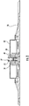
Fig. 2 is a cross-sectional elevational view of the flush static plate, taken along line 2-2 ifFig. 1 , illustrating the heater housing that includes a heater; -
Fig. 3 is an enlarged cross-sectional perspective view of the sensor module housing shown inFig. 1 , illustrating the thermal isolation puck which forms part of the thermal management system of the subject invention; -
Fig. 4 is a perspective of the thermal puck shown inFig, 3 ; -
Fig. 5 is another perspective view of the thermal puck shown inFig. 4 ; -
Fig. 6 is a cross-sectional view of the thermal puck taken along line 6-6 ofFig. 4 ; -
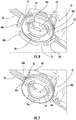
Fig. 7 is a perspective view of the sensor module housing shown inFig. 1 , as viewed from below, illustrating the thermal moat structures formed in the bottom surface of the thermal isolation puck and the thermal moat structures formed in the exterior surface of the bottom wall of the module housing; -
Fig. 8 is an enlarged localized view of the sensor module housing shown inFig. 7 , with the bottom wall broken away to illustrate the thermal isolation puck positioned in the reception port in the bottom wall of the housing; -
Fig. 9 is an alternative embodiment of the sensor module housing shown inFig. 7 , wherein thermal moat structures are formed in the interior surface of the bottom wall of the module housing; -
Fig. 10 is an enlarged cross-sectional perspective view of the sensor module housing shown inFig. 1 , illustrating another embodiment of the thermal isolation puck of the subject invention; -
Fig. 11 is a perspective view of the thermal isolation puck shown inFig. 10 ; -
Fig. 12 is a cross-sectional perspective view of the thermal isolation puck, taken along line 12-12 ofFig. 11 ; -
Fig. 13 is a perspective view of the sensor module housing shown inFig. 10 , as viewed from below, illustrating the thermal moat structures formed in the exterior surface of the bottom wall of the module housing; -
Fig. 14 is an enlarged localized view of the sensor module housing shown inFig. 13 , with the bottom wall broken away to illustrate the thermal puck positioned in the reception port in the bottom wall of the housing; and -
Fig. 15 is an alternative embodiment of the sensor module housing shown inFig. 13 , wherein thermal moat structures are formed in the interior surface of the bottom wall of the module housing. - Referring now to the drawings wherein like reference numeral identify similar features or structures of the several embodiments of the subject invention, there is illustrated in
Fig. 1 asensor module housing 10 associated with an adjacent air data measurement device in the form of a flushstatic plate 30 that is mounted on a structural panel of an aircraft (not shown). The flushstatic plate 30 contains a heater (seeFig. 2 ) and it works in concert with the thermal management system of the subject invention. An example of a flush static plate with which the thermal management system of the subject invention could operate is disclosed inU.S. Patent No. 8,365,591 . - Referring to
Fig. 2 , the flushstatic plate 30 includes an outerprotective cover 32 that encloses aheater housing 34. Theheater housing 34 is adapted and configured to support a heater that functions to control the local thermal environment of the flushstatic plate 30. The heater could be configured as a wire coil or a similar structure that would complement the geometry for theheater housing 34. Aheater cap 36 sits atop and extends from theheater housing 34 and through the outerprotective cover 32 of the flushstatic plate 30. Acentral bore 38 extends through theheater cap 36 to form a pneumatic pathway between the flushstatic plate 30 and thesensor module housing 10, as described in more detail below. It is envisioned that theheater cap 36 could be formed integral with or separate from theheater housing 34. - Referring now to
Fig. 3 , thesensor module housing 10 is made from a lightweight metallic material that has a relatively high thermal conductivity, such as, for example, aluminum or a similar metallic material. The sensor module housing 10 encloses apressure manifold 12 and associated printedcircuit boards pressure manifold 12 defines an internalpneumatic pressure path 18. The printedcircuit boards electrical connectors 22 and 24 (seeFig, 1 ) that provide input/output communications with the air data computer of the aircraft. - As best seen in
Fig. 3 , thesensor module housing 10 also includes athermal isolation puck 20 that is installed within areception port 26 formed in thebottom wall 28 of thesensor module housing 10 and fastened to thepressure manifold 12 in such a manner so as to communicate pneumatically with thepneumatic pressure path 18 defined therein. Thethermal isolation puck 20 is a key component of the thermal management system of the subject invention. As explained in more detail below, thethermal isolation puck 20 is formed from a metallic material that has a relatively low thermal conductivity, such as, for example, stainless steel or a similar metallic material that will reduce the rate at which thermal energy from the heater located within the adjacent flushstatic plate 30 is lost to thebottom wall 28 of thesensor module housing 10 during ground and flight operations. - Those skilled in the art will readily appreciate that the incorporation of the
thermal isolation puck 20 into the system of the subject invention results in increased operating temperatures along the pressure path, reducing the likelihood of moisture condensation within thesensor module housing 10 and increasing the efficiency of moisture removal. Furthermore, the temperature of thesensor module housing 10 is decreased, resulting in lower critical component operating temperatures and improved reliability. - Referring to
Figs. 4 through 7 , thethermal isolation puck 20 includes anupper body portion 40 and alower flange portion 42. Theupper body portion 40 has aninterior bore 44 extending therethrough to receive anupper neck portion 38 of theheater cap 36. Theupper neck portion 38 of theheater cap 36 includes asealing ring 35 for sealing against an interior surface of thebore 44 of theupper body portion 40. Acentral bore 37 extends through theheater cap 36 to communicate pneumatically with the interior bore 44 of thethermal isolation puck 20. - The
lower flange portion 44 of thethermal isolation puck 20 includes anannular channel 46 formed on a peripheral surface thereof for supporting a sealing ring 48 (seeFig. 3 ) to seal against an inner peripheral sealingsurface 25 of thereception port 26 formed in thebottom wall 28 of thesensor module housing 10. Those skilled in the art will readily appreciate that alternative means can be used to provide a seal between thelower flange portion 44 of thethermal isolation puck 20 and the inner peripheral sealingsurface 25 of thereception port 26, such as, for example, a face seal or the like. - As best seen in
Fig. 4 , three circumferentially spacedfastener reception ports 40a-40c are formed in theupper body portion 40 of thethermal isolation puck 20 to receiverespective fasteners 45 that secure thepuck 20 to thepressure manifold 12 insensor module housing 10. Those skilled in the art will readily appreciate that alternative means can be used to secure thethermal isolation puck 20 within thesensor module housing 10. For example, thethermal isolation puck 20 can be bonded, threaded or press-fit into thereception port 26 in thebottom wall 28 of thesensor module housing 10. - A
central port 50 is formed in theupper body portion 40 of thethermal isolation puck 20, which defines part of the pneumatic pressure path of the system. Thecentral port 50 communicates pneumatically with thepneumatic pressure path 18 in thepressure manifold 12. Thecentral port 50 pneumatically communicates with a plurality of circumferentially spacedpassageways 52 that distributively communicate with the interior bore 44 of thethermal isolation puck 20, as shown for example inFig. 6 . As best seen inFig. 3 , anannular face seal 54 is seated between the bottom surface of thepressure manifold 12 and the upper surface of theupper body portion 40 of thethermal puck 20. Those skilled in the art will readily appreciate that alternative sealing features could be employed in this location. - The
thermal isolation puck 20 is formed with a thermal impedance region that extends at least partially about theupper body portion 40 radially inward of theannular channel 46 in thelower flange portion 42. The thermal impendence region further reduces the rate at which thermal energy is lost to thebottom wall 28 of thesensor module housing 10. It includes three evenly spacedchannels 56a-56c that extend through the bottom surface of thelower flange portion 42 of thethermal isolation puck 20, which are best seen inFig. 5 . - Referring now to
Figs. 7 and8 , a thermal impedance region is also formed in an exterior surface of thebottom wall 28 of thesensor module housing 10, at least partially surrounding the peripheral sealingsurface 25 of thereception port 26 formed therein to further reduce the rate at which thermal energy is lost to thesensor module housing 10. This thermal impedance region includes a four evenly spaced apartchannels 58a-58d. - Alternatively, as shown in
Fig. 9 , a thermal impedance region could be formed in the interior surface of thebottom wall 28 of thesensor module housing 10, at least partially surrounding the peripheral sealingsurface 25 of thereception port 26, as shown by way of example bychannels bottom wall 28 of thesensor module housing 10 can vary by design to optimize the effectiveness of the thermal management system of the subject invention. - Referring now to
Fig. 10 , there is illustrated once again thesensor module housing 10, along with an alternative embodiment of the thermal isolation puck, which forms part of the thermal management system of the subject invention, and which is designated generally byreference numeral 120. Thethermal isolation puck 120 includes anupper body portion 140 and alower flange portion 142. Theupper body portion 140 has aninterior bore 144 extending therethrough to receive theupper neck portion 38 of theheater cap 36 shown inFig. 2 . Thelower flange portion 142 has anannular channel 146 formed on a peripheral surface thereof for supporting a sealing ring 148 to seal against aperipheral sealing surface 25 of thereception port 22 formed in thebottom wall 24 of thesensor module housing 10. Alternative sealing features can be employed, including, for example, a face seal or the like. - Three circumferentially spaced
fastener reception ports 140a-140c surround theupper body portion 140 of thethermal isolation puck 120 to receiverespective fasteners 45 that secure thepuck 120 to thepressure manifold 12 insensor module housing 10. Alternative fastening means can be employed to secure thethermal isolation puck 120 within thesensor housing 10. Acentral port 150 surrounded by anannular sealing groove 152 is formed in theupper body portion 140 of thethermal isolation puck 120. Thecentral port 150 defines part of the pneumatic pressure path of the system and it communicates directly with the interior bore 144 of thethermal isolation puck 120, as best seen inFig. 12 . The sealinggroove 152 supports theannular seal 154 which seals against the undersurface of thepressure manifold 12, as seen inFig. 10 . Alternative sealing features may be utilized in this location. - The
thermal isolation puck 120 is formed with a thermal impedance region that is defined by achannel 156 that surrounds or extends at least partially around theupper body portion 140 of thethermal isolation puck 120 radially inward of theannular channel 146 in thelower flange portion 144 to further reduce the rate of thermal energy lost to thesensor module housing 10. Thethermal isolation puck 120 with itsthermal impedance channel 156, together with thethermal impendence channels 58a-58d formed in the exterior surface ofbottom wall 28 of thesensor module housing 10 shown inFigs. 13 and14 , or together with the thermal impedance channels (e.g., 68a and 68c) formed in the interior surface of thebottom wall 28 of thesensor module housing 10 shown inFig. 15 , form the new and useful thermal management system of the subject invention. Moreover, thethermal isolation puck 120 and the thermal impedance channels formed in thebottom wall 28 of thesensor module housing 10 serve to keep thermal energy generated by the heater in the flushstatic plate 30 advantageously contained within the area of the pneumatic path. - While the subject disclosure has been shown and described with reference to preferred embodiments, those skilled in the art will readily appreciate that changes and/or modifications may be made thereto without departing from the scope of the invention as defined by the claims.
Claims (15)
- A thermal management system for a sensor module, comprising:a) a housing (10) enclosing the sensor module and having a bottom wall (28) with a reception port (26) formed therein; andb) a thermal isolation puck (20) installed within the reception port formed in the bottom wall of the housing for reducing the rate at which thermal energy from a heater located within an adjacent flush static plate (30) is lost to the housing.
- A thermal management system as recited in Claim 1, wherein the thermal isolation puck includes an upper body portion (40) having an interior bore (44) extending therethrough to provide a pneumatic pathway between the housing and the flush static plate.
- A thermal management system as recited in Claim 2, wherein the thermal isolation puck includes a lower flange portion (42) having means for sealing (35) against a peripheral sealing surface of the reception port formed in the housing.
- A thermal management system as recited in Claim 2 or 3, wherein means (45) are provided for securing the upper body portion of the thermal isolation puck within the housing.
- A thermal management system as recited in Claim 3, wherein the thermal isolation puck is formed with a thermal impedance region that extends at least partially about the upper body portion radially inward of the lower flange portion to further reduce the rate at which thermal energy is lost to the housing.
- A thermal management system as recited in Claim 5, wherein the thermal impedance region is defined by a plurality of evenly spaced channels (68) that extend through a bottom surface of the lower flange portion of the thermal isolation puck.
- A thermal management system as recited in any preceding claim, wherein a thermal impedance region is formed in an exterior surface of the bottom wall of the housing at least partially surrounding the reception port formed therein to further reduce the rate of thermal energy lost to the housing.
- A thermal management system as recited in any preceding claim, wherein a thermal impedance region is formed in an interior surface of the bottom wall of the housing at least partially surrounding the reception port formed therein to further reduce the rate of thermal energy lost to the housing.
- A thermal management system as recited in Claim 7, wherein the thermal impedance region formed in the exterior surface of the bottom wall of the housing is defined by a plurality of evenly spaced channels.
- A thermal management system as recited in Claim 8, wherein the thermal impedance region formed in the interior surface of the bottom wall of the housing includes a plurality of evenly spaced channels.
- A thermal management system as recited in any preceding claim, wherein the housing is formed from a metallic material having a relatively high thermal conductivity and the thermal isolation puck is formed from a metallic material having a relatively low thermal conductivity.
- A thermal management system for a sensor module, comprising:a) a housing (10) formed from a metallic material that has a relatively high thermal conductivity and enclosing the sensor module;b) a flush static plate (30) adjacent a bottom wall of the housing and configured to contain a heater for controlling a local thermal environment; andc) a thermal isolation puck (20) formed from a metallic material that has a relatively low thermal conductivity and installed within a reception port formed in the bottom wall of the housing for reducing the rate at which thermal energy from the heater contained within the flush static plate is lost to the housing.
- A thermal management system as recited in Claim 12, wherein the thermal isolation puck has a thermal impedance region formed therein that extends at least partially about an upper body portion thereof to further reduce the rate at which thermal energy is lost to the housing.
- A thermal management system as recited in Claim 12, wherein a thermal impedance region is formed in an exterior surface of the bottom wall of the housing at least partially surrounding the reception port to further reduce the rate at which thermal energy is lost to the housing.
- A thermal management system as recited in Claim 12, wherein a thermal impedance region is formed in an interior surface of the bottom wall of the housing at least partially surrounding the reception port to further reduce the rate at which thermal energy is lost to the housing.
Applications Claiming Priority (1)
| Application Number | Priority Date | Filing Date | Title |
|---|---|---|---|
| US16/367,644 US11486785B2 (en) | 2019-03-28 | 2019-03-28 | Thermal management system for air data sensor module |
Publications (2)
| Publication Number | Publication Date |
|---|---|
| EP3715263A1 true EP3715263A1 (en) | 2020-09-30 |
| EP3715263B1 EP3715263B1 (en) | 2021-11-03 |
Family
ID=68808063
Family Applications (1)
| Application Number | Title | Priority Date | Filing Date |
|---|---|---|---|
| EP19213954.1A Active EP3715263B1 (en) | 2019-03-28 | 2019-12-05 | Thermal management system for air data sensor module |
Country Status (4)
| Country | Link |
|---|---|
| US (1) | US11486785B2 (en) |
| EP (1) | EP3715263B1 (en) |
| BR (1) | BR102019026537A2 (en) |
| CA (1) | CA3064688A1 (en) |
Families Citing this family (4)
| Publication number | Priority date | Publication date | Assignee | Title |
|---|---|---|---|---|
| US11181545B2 (en) | 2017-08-17 | 2021-11-23 | Rosemount Aerospace Inc. | Angle of attack sensor with thermal enhancement |
| US11162970B2 (en) | 2019-06-17 | 2021-11-02 | Rosemount Aerospace Inc. | Angle of attack sensor |
| US11649057B2 (en) * | 2019-12-13 | 2023-05-16 | Rosemount Aerospace Inc. | Static plate heating arrangement |
| JP7704564B2 (en) * | 2021-05-10 | 2025-07-08 | アズビル株式会社 | diaphragm vacuum gauge |
Citations (3)
| Publication number | Priority date | Publication date | Assignee | Title |
|---|---|---|---|---|
| US3400582A (en) * | 1967-05-08 | 1968-09-10 | Eric S. Warner | Boat speed indicator |
| US8365591B2 (en) | 2010-11-15 | 2013-02-05 | Rosemount Aerospace Inc. | Static port apparatus |
| DE202014105763U1 (en) * | 2014-11-28 | 2016-01-07 | Argos Messtechnik Gmbh | Device for analyzing measuring gases, in particular breathing air |
Family Cites Families (12)
| Publication number | Priority date | Publication date | Assignee | Title |
|---|---|---|---|---|
| US4830164A (en) * | 1985-10-10 | 1989-05-16 | Hays Bill J | Heat puck for clutches and flywheels |
| US6510740B1 (en) | 1999-09-28 | 2003-01-28 | Rosemount Inc. | Thermal management in a pressure transmitter |
| DE10146321B4 (en) * | 2001-09-20 | 2008-08-14 | Robert Bosch Gmbh | Sensor module with a sensor element, which is surrounded by a heating element |
| US6672152B2 (en) | 2001-12-21 | 2004-01-06 | Honeywell International Inc. | Flush surface air data sensor |
| US20080190174A1 (en) * | 2005-05-10 | 2008-08-14 | Berend Jan Kooi | Sensor Module Package |
| US7597018B2 (en) | 2007-04-11 | 2009-10-06 | Rosemount Aerospace Inc. | Pneumatic line isolation and heating for air data probes |
| US7748268B2 (en) | 2008-07-13 | 2010-07-06 | Brooks Instrument, Llc | Thermal flow meter |
| US8037750B2 (en) * | 2009-10-29 | 2011-10-18 | Rosemount Aerospace, Inc. | Impending icing probe with thermal isolation pedestal |
| US8776608B2 (en) | 2011-10-31 | 2014-07-15 | Rosemount Inc. | Coplanar process fluid pressure sensor module |
| US11181545B2 (en) * | 2017-08-17 | 2021-11-23 | Rosemount Aerospace Inc. | Angle of attack sensor with thermal enhancement |
| US10877062B2 (en) * | 2018-05-09 | 2020-12-29 | Rosemount Aerospace Inc. | Aft-located heated ramp for ice and water management of angle of attack sensors |
| US10928416B2 (en) * | 2018-05-09 | 2021-02-23 | Rosemount Aerospace Inc. | Dual heated ramp for ice and water management in angle of attack sensors |
-
2019
- 2019-03-28 US US16/367,644 patent/US11486785B2/en active Active
- 2019-12-05 EP EP19213954.1A patent/EP3715263B1/en active Active
- 2019-12-10 CA CA3064688A patent/CA3064688A1/en active Pending
- 2019-12-13 BR BR102019026537-0A patent/BR102019026537A2/en unknown
Patent Citations (3)
| Publication number | Priority date | Publication date | Assignee | Title |
|---|---|---|---|---|
| US3400582A (en) * | 1967-05-08 | 1968-09-10 | Eric S. Warner | Boat speed indicator |
| US8365591B2 (en) | 2010-11-15 | 2013-02-05 | Rosemount Aerospace Inc. | Static port apparatus |
| DE202014105763U1 (en) * | 2014-11-28 | 2016-01-07 | Argos Messtechnik Gmbh | Device for analyzing measuring gases, in particular breathing air |
Also Published As
| Publication number | Publication date |
|---|---|
| US20200309630A1 (en) | 2020-10-01 |
| EP3715263B1 (en) | 2021-11-03 |
| US11486785B2 (en) | 2022-11-01 |
| CA3064688A1 (en) | 2020-09-28 |
| BR102019026537A2 (en) | 2020-10-13 |
Similar Documents
| Publication | Publication Date | Title |
|---|---|---|
| EP3715263B1 (en) | Thermal management system for air data sensor module | |
| US10343793B2 (en) | Silicone encapsulated aircraft LED light | |
| US20130258583A1 (en) | Composite material fadec box support | |
| EP2572977B1 (en) | Occluding member for opening | |
| US10720728B2 (en) | Electrical connector sealing system | |
| US8845898B2 (en) | APU fuel filter housing scupper | |
| US10040570B2 (en) | Sensing orifice for an aircraft | |
| US20130283815A1 (en) | Integral cooling for servo valve | |
| JP5832564B2 (en) | Numerical control device with a sealed display unit | |
| EP2934076B1 (en) | Electronics enclosure | |
| BR102016008076A2 (en) | sensor package, and collector for a mems sensor package | |
| CN106370345A (en) | Multichannel pressure scanning valve | |
| CN213688082U (en) | Carrier rocket | |
| US9933081B2 (en) | Bursting disc with thermal insulation | |
| US11415478B2 (en) | Protective housing for protecting an electronic device from environmental conditions | |
| CN109573094B (en) | Thermal protection device based on butt joint of aircraft cabin sections | |
| JP2017101793A (en) | Electronic device and filter device | |
| US9321519B2 (en) | Support plate for the passage of systems between two zones with different pressurizations of an aircraft | |
| US10570918B2 (en) | Fan having outer electronics | |
| CN210834948U (en) | Structure for improving installation reliability of speed sensor | |
| EP2870008B1 (en) | System and method for thermal mitigation for tire pressure measurement electronics | |
| US11067462B2 (en) | Sensor | |
| CN218787343U (en) | Pneumatic electric field device | |
| KR20150019240A (en) | Heat-insulating-vaccum-panel for high speed vehicle and manufacture method thereof | |
| US20250033755A1 (en) | System for Attaching Heat Generating Equipment to an Exterior of an Aircraft |
Legal Events
| Date | Code | Title | Description |
|---|---|---|---|
| PUAI | Public reference made under article 153(3) epc to a published international application that has entered the european phase |
Free format text: ORIGINAL CODE: 0009012 |
|
| STAA | Information on the status of an ep patent application or granted ep patent |
Free format text: STATUS: THE APPLICATION HAS BEEN PUBLISHED |
|
| AK | Designated contracting states |
Kind code of ref document: A1 Designated state(s): AL AT BE BG CH CY CZ DE DK EE ES FI FR GB GR HR HU IE IS IT LI LT LU LV MC MK MT NL NO PL PT RO RS SE SI SK SM TR |
|
| AX | Request for extension of the european patent |
Extension state: BA ME |
|
| STAA | Information on the status of an ep patent application or granted ep patent |
Free format text: STATUS: REQUEST FOR EXAMINATION WAS MADE |
|
| 17P | Request for examination filed |
Effective date: 20210330 |
|
| RBV | Designated contracting states (corrected) |
Designated state(s): AL AT BE BG CH CY CZ DE DK EE ES FI FR GB GR HR HU IE IS IT LI LT LU LV MC MK MT NL NO PL PT RO RS SE SI SK SM TR |
|
| GRAP | Despatch of communication of intention to grant a patent |
Free format text: ORIGINAL CODE: EPIDOSNIGR1 |
|
| STAA | Information on the status of an ep patent application or granted ep patent |
Free format text: STATUS: GRANT OF PATENT IS INTENDED |
|
| INTG | Intention to grant announced |
Effective date: 20210519 |
|
| GRAS | Grant fee paid |
Free format text: ORIGINAL CODE: EPIDOSNIGR3 |
|
| GRAA | (expected) grant |
Free format text: ORIGINAL CODE: 0009210 |
|
| STAA | Information on the status of an ep patent application or granted ep patent |
Free format text: STATUS: THE PATENT HAS BEEN GRANTED |
|
| AK | Designated contracting states |
Kind code of ref document: B1 Designated state(s): AL AT BE BG CH CY CZ DE DK EE ES FI FR GB GR HR HU IE IS IT LI LT LU LV MC MK MT NL NO PL PT RO RS SE SI SK SM TR |
|
| REG | Reference to a national code |
Ref country code: GB Ref legal event code: FG4D |
|
| REG | Reference to a national code |
Ref country code: AT Ref legal event code: REF Ref document number: 1443764 Country of ref document: AT Kind code of ref document: T Effective date: 20211115 Ref country code: CH Ref legal event code: EP |
|
| REG | Reference to a national code |
Ref country code: IE Ref legal event code: FG4D |
|
| REG | Reference to a national code |
Ref country code: DE Ref legal event code: R096 Ref document number: 602019008939 Country of ref document: DE |
|
| REG | Reference to a national code |
Ref country code: LT Ref legal event code: MG9D |
|
| REG | Reference to a national code |
Ref country code: NL Ref legal event code: MP Effective date: 20211103 |
|
| REG | Reference to a national code |
Ref country code: AT Ref legal event code: MK05 Ref document number: 1443764 Country of ref document: AT Kind code of ref document: T Effective date: 20211103 |
|
| PG25 | Lapsed in a contracting state [announced via postgrant information from national office to epo] |
Ref country code: RS Free format text: LAPSE BECAUSE OF FAILURE TO SUBMIT A TRANSLATION OF THE DESCRIPTION OR TO PAY THE FEE WITHIN THE PRESCRIBED TIME-LIMIT Effective date: 20211103 Ref country code: LT Free format text: LAPSE BECAUSE OF FAILURE TO SUBMIT A TRANSLATION OF THE DESCRIPTION OR TO PAY THE FEE WITHIN THE PRESCRIBED TIME-LIMIT Effective date: 20211103 Ref country code: FI Free format text: LAPSE BECAUSE OF FAILURE TO SUBMIT A TRANSLATION OF THE DESCRIPTION OR TO PAY THE FEE WITHIN THE PRESCRIBED TIME-LIMIT Effective date: 20211103 Ref country code: BG Free format text: LAPSE BECAUSE OF FAILURE TO SUBMIT A TRANSLATION OF THE DESCRIPTION OR TO PAY THE FEE WITHIN THE PRESCRIBED TIME-LIMIT Effective date: 20220203 Ref country code: AT Free format text: LAPSE BECAUSE OF FAILURE TO SUBMIT A TRANSLATION OF THE DESCRIPTION OR TO PAY THE FEE WITHIN THE PRESCRIBED TIME-LIMIT Effective date: 20211103 |
|
| PG25 | Lapsed in a contracting state [announced via postgrant information from national office to epo] |
Ref country code: IS Free format text: LAPSE BECAUSE OF FAILURE TO SUBMIT A TRANSLATION OF THE DESCRIPTION OR TO PAY THE FEE WITHIN THE PRESCRIBED TIME-LIMIT Effective date: 20220303 Ref country code: SE Free format text: LAPSE BECAUSE OF FAILURE TO SUBMIT A TRANSLATION OF THE DESCRIPTION OR TO PAY THE FEE WITHIN THE PRESCRIBED TIME-LIMIT Effective date: 20211103 Ref country code: PT Free format text: LAPSE BECAUSE OF FAILURE TO SUBMIT A TRANSLATION OF THE DESCRIPTION OR TO PAY THE FEE WITHIN THE PRESCRIBED TIME-LIMIT Effective date: 20220303 Ref country code: PL Free format text: LAPSE BECAUSE OF FAILURE TO SUBMIT A TRANSLATION OF THE DESCRIPTION OR TO PAY THE FEE WITHIN THE PRESCRIBED TIME-LIMIT Effective date: 20211103 Ref country code: NO Free format text: LAPSE BECAUSE OF FAILURE TO SUBMIT A TRANSLATION OF THE DESCRIPTION OR TO PAY THE FEE WITHIN THE PRESCRIBED TIME-LIMIT Effective date: 20220203 Ref country code: NL Free format text: LAPSE BECAUSE OF FAILURE TO SUBMIT A TRANSLATION OF THE DESCRIPTION OR TO PAY THE FEE WITHIN THE PRESCRIBED TIME-LIMIT Effective date: 20211103 Ref country code: LV Free format text: LAPSE BECAUSE OF FAILURE TO SUBMIT A TRANSLATION OF THE DESCRIPTION OR TO PAY THE FEE WITHIN THE PRESCRIBED TIME-LIMIT Effective date: 20211103 Ref country code: HR Free format text: LAPSE BECAUSE OF FAILURE TO SUBMIT A TRANSLATION OF THE DESCRIPTION OR TO PAY THE FEE WITHIN THE PRESCRIBED TIME-LIMIT Effective date: 20211103 Ref country code: GR Free format text: LAPSE BECAUSE OF FAILURE TO SUBMIT A TRANSLATION OF THE DESCRIPTION OR TO PAY THE FEE WITHIN THE PRESCRIBED TIME-LIMIT Effective date: 20220204 Ref country code: ES Free format text: LAPSE BECAUSE OF FAILURE TO SUBMIT A TRANSLATION OF THE DESCRIPTION OR TO PAY THE FEE WITHIN THE PRESCRIBED TIME-LIMIT Effective date: 20211103 |
|
| PG25 | Lapsed in a contracting state [announced via postgrant information from national office to epo] |
Ref country code: SM Free format text: LAPSE BECAUSE OF FAILURE TO SUBMIT A TRANSLATION OF THE DESCRIPTION OR TO PAY THE FEE WITHIN THE PRESCRIBED TIME-LIMIT Effective date: 20211103 Ref country code: SK Free format text: LAPSE BECAUSE OF FAILURE TO SUBMIT A TRANSLATION OF THE DESCRIPTION OR TO PAY THE FEE WITHIN THE PRESCRIBED TIME-LIMIT Effective date: 20211103 Ref country code: RO Free format text: LAPSE BECAUSE OF FAILURE TO SUBMIT A TRANSLATION OF THE DESCRIPTION OR TO PAY THE FEE WITHIN THE PRESCRIBED TIME-LIMIT Effective date: 20211103 Ref country code: EE Free format text: LAPSE BECAUSE OF FAILURE TO SUBMIT A TRANSLATION OF THE DESCRIPTION OR TO PAY THE FEE WITHIN THE PRESCRIBED TIME-LIMIT Effective date: 20211103 Ref country code: DK Free format text: LAPSE BECAUSE OF FAILURE TO SUBMIT A TRANSLATION OF THE DESCRIPTION OR TO PAY THE FEE WITHIN THE PRESCRIBED TIME-LIMIT Effective date: 20211103 Ref country code: CZ Free format text: LAPSE BECAUSE OF FAILURE TO SUBMIT A TRANSLATION OF THE DESCRIPTION OR TO PAY THE FEE WITHIN THE PRESCRIBED TIME-LIMIT Effective date: 20211103 |
|
| REG | Reference to a national code |
Ref country code: DE Ref legal event code: R097 Ref document number: 602019008939 Country of ref document: DE |
|
| PG25 | Lapsed in a contracting state [announced via postgrant information from national office to epo] |
Ref country code: MC Free format text: LAPSE BECAUSE OF FAILURE TO SUBMIT A TRANSLATION OF THE DESCRIPTION OR TO PAY THE FEE WITHIN THE PRESCRIBED TIME-LIMIT Effective date: 20211103 |
|
| PLBE | No opposition filed within time limit |
Free format text: ORIGINAL CODE: 0009261 |
|
| STAA | Information on the status of an ep patent application or granted ep patent |
Free format text: STATUS: NO OPPOSITION FILED WITHIN TIME LIMIT |
|
| REG | Reference to a national code |
Ref country code: BE Ref legal event code: MM Effective date: 20211231 |
|
| 26N | No opposition filed |
Effective date: 20220804 |
|
| PG25 | Lapsed in a contracting state [announced via postgrant information from national office to epo] |
Ref country code: LU Free format text: LAPSE BECAUSE OF NON-PAYMENT OF DUE FEES Effective date: 20211205 Ref country code: IE Free format text: LAPSE BECAUSE OF NON-PAYMENT OF DUE FEES Effective date: 20211205 Ref country code: AL Free format text: LAPSE BECAUSE OF FAILURE TO SUBMIT A TRANSLATION OF THE DESCRIPTION OR TO PAY THE FEE WITHIN THE PRESCRIBED TIME-LIMIT Effective date: 20211103 |
|
| PG25 | Lapsed in a contracting state [announced via postgrant information from national office to epo] |
Ref country code: SI Free format text: LAPSE BECAUSE OF FAILURE TO SUBMIT A TRANSLATION OF THE DESCRIPTION OR TO PAY THE FEE WITHIN THE PRESCRIBED TIME-LIMIT Effective date: 20211103 Ref country code: BE Free format text: LAPSE BECAUSE OF NON-PAYMENT OF DUE FEES Effective date: 20211231 |
|
| PG25 | Lapsed in a contracting state [announced via postgrant information from national office to epo] |
Ref country code: IT Free format text: LAPSE BECAUSE OF FAILURE TO SUBMIT A TRANSLATION OF THE DESCRIPTION OR TO PAY THE FEE WITHIN THE PRESCRIBED TIME-LIMIT Effective date: 20211103 |
|
| PG25 | Lapsed in a contracting state [announced via postgrant information from national office to epo] |
Ref country code: CY Free format text: LAPSE BECAUSE OF FAILURE TO SUBMIT A TRANSLATION OF THE DESCRIPTION OR TO PAY THE FEE WITHIN THE PRESCRIBED TIME-LIMIT Effective date: 20211103 |
|
| PG25 | Lapsed in a contracting state [announced via postgrant information from national office to epo] |
Ref country code: HU Free format text: LAPSE BECAUSE OF FAILURE TO SUBMIT A TRANSLATION OF THE DESCRIPTION OR TO PAY THE FEE WITHIN THE PRESCRIBED TIME-LIMIT; INVALID AB INITIO Effective date: 20191205 |
|
| REG | Reference to a national code |
Ref country code: CH Ref legal event code: PL |
|
| PG25 | Lapsed in a contracting state [announced via postgrant information from national office to epo] |
Ref country code: LI Free format text: LAPSE BECAUSE OF NON-PAYMENT OF DUE FEES Effective date: 20221231 Ref country code: CH Free format text: LAPSE BECAUSE OF NON-PAYMENT OF DUE FEES Effective date: 20221231 |
|
| PG25 | Lapsed in a contracting state [announced via postgrant information from national office to epo] |
Ref country code: MK Free format text: LAPSE BECAUSE OF FAILURE TO SUBMIT A TRANSLATION OF THE DESCRIPTION OR TO PAY THE FEE WITHIN THE PRESCRIBED TIME-LIMIT Effective date: 20211103 |
|
| PG25 | Lapsed in a contracting state [announced via postgrant information from national office to epo] |
Ref country code: MT Free format text: LAPSE BECAUSE OF FAILURE TO SUBMIT A TRANSLATION OF THE DESCRIPTION OR TO PAY THE FEE WITHIN THE PRESCRIBED TIME-LIMIT Effective date: 20211103 |
|
| PG25 | Lapsed in a contracting state [announced via postgrant information from national office to epo] |
Ref country code: TR Free format text: LAPSE BECAUSE OF FAILURE TO SUBMIT A TRANSLATION OF THE DESCRIPTION OR TO PAY THE FEE WITHIN THE PRESCRIBED TIME-LIMIT Effective date: 20211103 |
|
| PGFP | Annual fee paid to national office [announced via postgrant information from national office to epo] |
Ref country code: DE Payment date: 20251126 Year of fee payment: 7 |
|
| PGFP | Annual fee paid to national office [announced via postgrant information from national office to epo] |
Ref country code: GB Payment date: 20251120 Year of fee payment: 7 |
|
| PGFP | Annual fee paid to national office [announced via postgrant information from national office to epo] |
Ref country code: FR Payment date: 20251120 Year of fee payment: 7 |
|
| P01 | Opt-out of the competence of the unified patent court (upc) registered |
Free format text: CASE NUMBER: UPC_APP_0018947_3715263/2025 Effective date: 20251222 |