EP3715262A1 - Ram air turbine shaft whirl damper - Google Patents
Ram air turbine shaft whirl damper Download PDFInfo
- Publication number
- EP3715262A1 EP3715262A1 EP19208897.9A EP19208897A EP3715262A1 EP 3715262 A1 EP3715262 A1 EP 3715262A1 EP 19208897 A EP19208897 A EP 19208897A EP 3715262 A1 EP3715262 A1 EP 3715262A1
- Authority
- EP
- European Patent Office
- Prior art keywords
- whirl
- rat
- bearing
- housing
- turbine shaft
- Prior art date
- Legal status (The legal status is an assumption and is not a legal conclusion. Google has not performed a legal analysis and makes no representation as to the accuracy of the status listed.)
- Granted
Links
Images
Classifications
-
- F—MECHANICAL ENGINEERING; LIGHTING; HEATING; WEAPONS; BLASTING
- F03—MACHINES OR ENGINES FOR LIQUIDS; WIND, SPRING, OR WEIGHT MOTORS; PRODUCING MECHANICAL POWER OR A REACTIVE PROPULSIVE THRUST, NOT OTHERWISE PROVIDED FOR
- F03D—WIND MOTORS
- F03D7/00—Controlling wind motors
- F03D7/02—Controlling wind motors the wind motors having rotation axis substantially parallel to the air flow entering the rotor
- F03D7/0296—Controlling wind motors the wind motors having rotation axis substantially parallel to the air flow entering the rotor to prevent, counteract or reduce noise emissions
-
- B—PERFORMING OPERATIONS; TRANSPORTING
- B64—AIRCRAFT; AVIATION; COSMONAUTICS
- B64D—EQUIPMENT FOR FITTING IN OR TO AIRCRAFT; FLIGHT SUITS; PARACHUTES; ARRANGEMENT OR MOUNTING OF POWER PLANTS OR PROPULSION TRANSMISSIONS IN AIRCRAFT
- B64D41/00—Power installations for auxiliary purposes
- B64D41/007—Ram air turbines
-
- F—MECHANICAL ENGINEERING; LIGHTING; HEATING; WEAPONS; BLASTING
- F01—MACHINES OR ENGINES IN GENERAL; ENGINE PLANTS IN GENERAL; STEAM ENGINES
- F01D—NON-POSITIVE DISPLACEMENT MACHINES OR ENGINES, e.g. STEAM TURBINES
- F01D15/00—Adaptations of machines or engines for special use; Combinations of engines with devices driven thereby
- F01D15/10—Adaptations for driving, or combinations with, electric generators
-
- F—MECHANICAL ENGINEERING; LIGHTING; HEATING; WEAPONS; BLASTING
- F01—MACHINES OR ENGINES IN GENERAL; ENGINE PLANTS IN GENERAL; STEAM ENGINES
- F01D—NON-POSITIVE DISPLACEMENT MACHINES OR ENGINES, e.g. STEAM TURBINES
- F01D25/00—Component parts, details, or accessories, not provided for in, or of interest apart from, other groups
- F01D25/16—Arrangement of bearings; Supporting or mounting bearings in casings
- F01D25/162—Bearing supports
- F01D25/164—Flexible supports; Vibration damping means associated with the bearing
-
- F—MECHANICAL ENGINEERING; LIGHTING; HEATING; WEAPONS; BLASTING
- F01—MACHINES OR ENGINES IN GENERAL; ENGINE PLANTS IN GENERAL; STEAM ENGINES
- F01D—NON-POSITIVE DISPLACEMENT MACHINES OR ENGINES, e.g. STEAM TURBINES
- F01D5/00—Blades; Blade-carrying members; Heating, heat-insulating, cooling or antivibration means on the blades or the members
- F01D5/02—Blade-carrying members, e.g. rotors
- F01D5/021—Blade-carrying members, e.g. rotors for flow machines or engines with only one axial stage
-
- F—MECHANICAL ENGINEERING; LIGHTING; HEATING; WEAPONS; BLASTING
- F01—MACHINES OR ENGINES IN GENERAL; ENGINE PLANTS IN GENERAL; STEAM ENGINES
- F01D—NON-POSITIVE DISPLACEMENT MACHINES OR ENGINES, e.g. STEAM TURBINES
- F01D5/00—Blades; Blade-carrying members; Heating, heat-insulating, cooling or antivibration means on the blades or the members
- F01D5/02—Blade-carrying members, e.g. rotors
- F01D5/10—Anti- vibration means
-
- F—MECHANICAL ENGINEERING; LIGHTING; HEATING; WEAPONS; BLASTING
- F03—MACHINES OR ENGINES FOR LIQUIDS; WIND, SPRING, OR WEIGHT MOTORS; PRODUCING MECHANICAL POWER OR A REACTIVE PROPULSIVE THRUST, NOT OTHERWISE PROVIDED FOR
- F03D—WIND MOTORS
- F03D1/00—Wind motors with rotation axis substantially parallel to the air flow entering the rotor
-
- F—MECHANICAL ENGINEERING; LIGHTING; HEATING; WEAPONS; BLASTING
- F03—MACHINES OR ENGINES FOR LIQUIDS; WIND, SPRING, OR WEIGHT MOTORS; PRODUCING MECHANICAL POWER OR A REACTIVE PROPULSIVE THRUST, NOT OTHERWISE PROVIDED FOR
- F03D—WIND MOTORS
- F03D1/00—Wind motors with rotation axis substantially parallel to the air flow entering the rotor
- F03D1/06—Rotors
- F03D1/065—Rotors characterised by their construction elements
- F03D1/0658—Arrangements for fixing wind-engaging parts to a hub
-
- F—MECHANICAL ENGINEERING; LIGHTING; HEATING; WEAPONS; BLASTING
- F03—MACHINES OR ENGINES FOR LIQUIDS; WIND, SPRING, OR WEIGHT MOTORS; PRODUCING MECHANICAL POWER OR A REACTIVE PROPULSIVE THRUST, NOT OTHERWISE PROVIDED FOR
- F03D—WIND MOTORS
- F03D80/00—Details, components or accessories not provided for in groups F03D1/00 - F03D17/00
- F03D80/70—Bearing or lubricating arrangements
-
- F—MECHANICAL ENGINEERING; LIGHTING; HEATING; WEAPONS; BLASTING
- F03—MACHINES OR ENGINES FOR LIQUIDS; WIND, SPRING, OR WEIGHT MOTORS; PRODUCING MECHANICAL POWER OR A REACTIVE PROPULSIVE THRUST, NOT OTHERWISE PROVIDED FOR
- F03D—WIND MOTORS
- F03D9/00—Adaptations of wind motors for special use; Combinations of wind motors with apparatus driven thereby; Wind motors specially adapted for installation in particular locations
- F03D9/20—Wind motors characterised by the driven apparatus
- F03D9/25—Wind motors characterised by the driven apparatus the apparatus being an electrical generator
-
- F—MECHANICAL ENGINEERING; LIGHTING; HEATING; WEAPONS; BLASTING
- F03—MACHINES OR ENGINES FOR LIQUIDS; WIND, SPRING, OR WEIGHT MOTORS; PRODUCING MECHANICAL POWER OR A REACTIVE PROPULSIVE THRUST, NOT OTHERWISE PROVIDED FOR
- F03D—WIND MOTORS
- F03D9/00—Adaptations of wind motors for special use; Combinations of wind motors with apparatus driven thereby; Wind motors specially adapted for installation in particular locations
- F03D9/30—Wind motors specially adapted for installation in particular locations
- F03D9/32—Wind motors specially adapted for installation in particular locations on moving objects, e.g. vehicles
-
- F—MECHANICAL ENGINEERING; LIGHTING; HEATING; WEAPONS; BLASTING
- F16—ENGINEERING ELEMENTS AND UNITS; GENERAL MEASURES FOR PRODUCING AND MAINTAINING EFFECTIVE FUNCTIONING OF MACHINES OR INSTALLATIONS; THERMAL INSULATION IN GENERAL
- F16C—SHAFTS; FLEXIBLE SHAFTS; ELEMENTS OR CRANKSHAFT MECHANISMS; ROTARY BODIES OTHER THAN GEARING ELEMENTS; BEARINGS
- F16C27/00—Elastic or yielding bearings or bearing supports, for exclusively rotary movement
- F16C27/04—Ball or roller bearings, e.g. with resilient rolling bodies
-
- F—MECHANICAL ENGINEERING; LIGHTING; HEATING; WEAPONS; BLASTING
- F16—ENGINEERING ELEMENTS AND UNITS; GENERAL MEASURES FOR PRODUCING AND MAINTAINING EFFECTIVE FUNCTIONING OF MACHINES OR INSTALLATIONS; THERMAL INSULATION IN GENERAL
- F16C—SHAFTS; FLEXIBLE SHAFTS; ELEMENTS OR CRANKSHAFT MECHANISMS; ROTARY BODIES OTHER THAN GEARING ELEMENTS; BEARINGS
- F16C27/00—Elastic or yielding bearings or bearing supports, for exclusively rotary movement
- F16C27/06—Elastic or yielding bearings or bearing supports, for exclusively rotary movement by means of parts of rubber or like materials
-
- F—MECHANICAL ENGINEERING; LIGHTING; HEATING; WEAPONS; BLASTING
- F16—ENGINEERING ELEMENTS AND UNITS; GENERAL MEASURES FOR PRODUCING AND MAINTAINING EFFECTIVE FUNCTIONING OF MACHINES OR INSTALLATIONS; THERMAL INSULATION IN GENERAL
- F16C—SHAFTS; FLEXIBLE SHAFTS; ELEMENTS OR CRANKSHAFT MECHANISMS; ROTARY BODIES OTHER THAN GEARING ELEMENTS; BEARINGS
- F16C35/00—Rigid support of bearing units; Housings, e.g. caps, covers
- F16C35/04—Rigid support of bearing units; Housings, e.g. caps, covers in the case of ball or roller bearings
- F16C35/06—Mounting or dismounting of ball or roller bearings; Fixing them onto shaft or in housing
- F16C35/067—Fixing them in a housing
-
- F—MECHANICAL ENGINEERING; LIGHTING; HEATING; WEAPONS; BLASTING
- F05—INDEXING SCHEMES RELATING TO ENGINES OR PUMPS IN VARIOUS SUBCLASSES OF CLASSES F01-F04
- F05B—INDEXING SCHEME RELATING TO WIND, SPRING, WEIGHT, INERTIA OR LIKE MOTORS, TO MACHINES OR ENGINES FOR LIQUIDS COVERED BY SUBCLASSES F03B, F03D AND F03G
- F05B2220/00—Application
- F05B2220/30—Application in turbines
- F05B2220/31—Application in turbines in ram-air turbines ("RATS")
-
- F—MECHANICAL ENGINEERING; LIGHTING; HEATING; WEAPONS; BLASTING
- F05—INDEXING SCHEMES RELATING TO ENGINES OR PUMPS IN VARIOUS SUBCLASSES OF CLASSES F01-F04
- F05B—INDEXING SCHEME RELATING TO WIND, SPRING, WEIGHT, INERTIA OR LIKE MOTORS, TO MACHINES OR ENGINES FOR LIQUIDS COVERED BY SUBCLASSES F03B, F03D AND F03G
- F05B2240/00—Components
- F05B2240/90—Mounting on supporting structures or systems
- F05B2240/93—Mounting on supporting structures or systems on a structure floating on a liquid surface
- F05B2240/932—Mounting on supporting structures or systems on a structure floating on a liquid surface which is a catamaran-like structure
-
- F—MECHANICAL ENGINEERING; LIGHTING; HEATING; WEAPONS; BLASTING
- F05—INDEXING SCHEMES RELATING TO ENGINES OR PUMPS IN VARIOUS SUBCLASSES OF CLASSES F01-F04
- F05B—INDEXING SCHEME RELATING TO WIND, SPRING, WEIGHT, INERTIA OR LIKE MOTORS, TO MACHINES OR ENGINES FOR LIQUIDS COVERED BY SUBCLASSES F03B, F03D AND F03G
- F05B2260/00—Function
- F05B2260/96—Preventing, counteracting or reducing vibration or noise
-
- F—MECHANICAL ENGINEERING; LIGHTING; HEATING; WEAPONS; BLASTING
- F05—INDEXING SCHEMES RELATING TO ENGINES OR PUMPS IN VARIOUS SUBCLASSES OF CLASSES F01-F04
- F05B—INDEXING SCHEME RELATING TO WIND, SPRING, WEIGHT, INERTIA OR LIKE MOTORS, TO MACHINES OR ENGINES FOR LIQUIDS COVERED BY SUBCLASSES F03B, F03D AND F03G
- F05B2260/00—Function
- F05B2260/96—Preventing, counteracting or reducing vibration or noise
- F05B2260/964—Preventing, counteracting or reducing vibration or noise by damping means
-
- F—MECHANICAL ENGINEERING; LIGHTING; HEATING; WEAPONS; BLASTING
- F05—INDEXING SCHEMES RELATING TO ENGINES OR PUMPS IN VARIOUS SUBCLASSES OF CLASSES F01-F04
- F05D—INDEXING SCHEME FOR ASPECTS RELATING TO NON-POSITIVE-DISPLACEMENT MACHINES OR ENGINES, GAS-TURBINES OR JET-PROPULSION PLANTS
- F05D2220/00—Application
- F05D2220/30—Application in turbines
- F05D2220/34—Application in turbines in ram-air turbines ("RATS")
-
- F—MECHANICAL ENGINEERING; LIGHTING; HEATING; WEAPONS; BLASTING
- F05—INDEXING SCHEMES RELATING TO ENGINES OR PUMPS IN VARIOUS SUBCLASSES OF CLASSES F01-F04
- F05D—INDEXING SCHEME FOR ASPECTS RELATING TO NON-POSITIVE-DISPLACEMENT MACHINES OR ENGINES, GAS-TURBINES OR JET-PROPULSION PLANTS
- F05D2260/00—Function
- F05D2260/96—Preventing, counteracting or reducing vibration or noise
-
- Y—GENERAL TAGGING OF NEW TECHNOLOGICAL DEVELOPMENTS; GENERAL TAGGING OF CROSS-SECTIONAL TECHNOLOGIES SPANNING OVER SEVERAL SECTIONS OF THE IPC; TECHNICAL SUBJECTS COVERED BY FORMER USPC CROSS-REFERENCE ART COLLECTIONS [XRACs] AND DIGESTS
- Y02—TECHNOLOGIES OR APPLICATIONS FOR MITIGATION OR ADAPTATION AGAINST CLIMATE CHANGE
- Y02E—REDUCTION OF GREENHOUSE GAS [GHG] EMISSIONS, RELATED TO ENERGY GENERATION, TRANSMISSION OR DISTRIBUTION
- Y02E10/00—Energy generation through renewable energy sources
- Y02E10/70—Wind energy
- Y02E10/72—Wind turbines with rotation axis in wind direction
-
- Y—GENERAL TAGGING OF NEW TECHNOLOGICAL DEVELOPMENTS; GENERAL TAGGING OF CROSS-SECTIONAL TECHNOLOGIES SPANNING OVER SEVERAL SECTIONS OF THE IPC; TECHNICAL SUBJECTS COVERED BY FORMER USPC CROSS-REFERENCE ART COLLECTIONS [XRACs] AND DIGESTS
- Y02—TECHNOLOGIES OR APPLICATIONS FOR MITIGATION OR ADAPTATION AGAINST CLIMATE CHANGE
- Y02T—CLIMATE CHANGE MITIGATION TECHNOLOGIES RELATED TO TRANSPORTATION
- Y02T50/00—Aeronautics or air transport
- Y02T50/60—Efficient propulsion technologies, e.g. for aircraft
Definitions
- This disclosure relates to ram air turbine (RAT) systems, more specifically to turbines of RAT systems.
- RAT ram air turbine
- RAT ram air turbine
- a ram air turbine can include a housing and a turbine shaft configured to connect to one or more turbine blades and be turned by the one or more blades.
- the turbine shaft can be disposed in the housing to rotate relative to the housing along a rotational axis.
- the RAT can include a first bearing and a second bearing mounted between the turbine shaft and the housing to allow the turbine shaft to rotate relative to the housing.
- the RAT can include a whirl reduction system configured to dampen or eliminate whirl around the rotational axis.
- the whirl reduction system can include a third bearing between the housing and the turbine shaft.
- the whirl reduction system can include a spring connected to the third bearing and to the housing to provide a spring force to the turbine shaft to bias the turbine shaft toward a whirl extent, e.g., to limit whirl.
- the whirl reduction system can include a damper connected to the third bearing and the housing.
- the damper can be connected to the third bearing and the housing with the spring.
- the third bearing can be positioned aft of both of the first bearing and the second bearing. Any other suitable position is contemplated herein. Any other suitable location, e.g., anywhere along the turbine axis, is contemplated herein.
- a center of gravity of the RAT can be forward of both of the first bearing and the second bearing. Any other suitable position for the center of gravity of the RAT is contemplated herein.
- an aircraft can include any suitable ram air turbine (RAT) disclosed herein (e.g., as described above). Any other suitable RAT for an aircraft is contemplated herein.
- RAT ram air turbine
- a method for reducing whirl of a ram air turbine can include providing a spring force and/or damping between a turbine shaft and housing to dampen and/or eliminate whirl of the RAT.
- Providing a spring force and/or damping can include providing both a spring force and damping.
- Providing a spring force can include providing a sufficient spring force to maintain a whirl extent under all loading conditions in flight.
- Damping the whirl can include reducing a whirl extent.
- Reducing a whirl extent can include changing a whirl orbit shape about a rotational axis.
- RAT ram air turbine
- a ram air turbine (RAT) 100 can include a housing 101 and a turbine shaft 103 configured to connect to one or more turbine blades 105 and be turned by the one or more blades 105.
- the turbine shaft 103 can be disposed in the housing 101 to rotate relative to the housing 101 along a rotational axis 109.
- the RAT turbine 100 can include a first bearing 111 and a second bearing 113 mounted between the turbine shaft 103 and the housing 101 to allow the turbine shaft 103 to rotate relative to the housing 101.
- the RAT turbine 100 can include a whirl reduction system 115 configured to dampen or eliminate whirl (e.g., orbiting around axis 109 up to whirl extent 117) around the rotational axis 109.
- the whirl reduction system 115 can include a third bearing 119 between the housing 101 and the turbine shaft 103.
- the whirl reduction system 115 can include a spring 121 connected to the third bearing 119 and to the housing 101 to provide a spring force to the turbine shaft 103 to bias the turbine shaft 103 toward a whirl extent 117, e.g., to limit whirl.
- the spring 121 can be selected to provide any suitable force (e.g., enough to hold the turbine shaft 103 in the whirl extent under all loading conditions to eliminate whirl).
- the whirl reduction system 115 can include a damper 123, e.g., connected to the third bearing 119 and the housing 101 to provide damping to the turbine shaft 103.
- the damper 123 can be connected to the third bearing 119 and the housing 101 with the spring 121. It is contemplated that the damper 123 can be in any other suitable location (e.g., a separate bearing), and/or can be used without a spring 121.
- the third bearing 119 can be positioned aft of both of the first bearing 111 and the second bearing 113, e.g., as shown (e.g., at the end of shaft to provide maximum moment arm to reduce the size of the spring 121 and/or damper 123). Any other suitable position (e.g., forward of both first and second bearings 111, 113), e.g., anywhere along the turbine axis, is contemplated herein.
- a third bearing 119 e.g., placed at a middle point between the first and second bearings 111, 113) can be used alone without a spring 121 or damper 123, for example.
- a center of gravity 125 of the RAT turbine 100 can be forward of both of the first bearing 111 and the second bearing 119. Any other suitable position for the center of gravity 125 of the RAT turbine 100 is contemplated herein.
- an aircraft can include any suitable ram air turbine (RAT) (e.g., RAT turbine 100) disclosed herein (e.g., as described above). Any other suitable RAT for an aircraft is contemplated herein.
- RAT ram air turbine
- a method for reducing whirl of a ram air turbine can include providing a spring force and/or damping between a turbine shaft and housing to dampen and/or eliminate whirl of the RAT.
- Providing a spring force and/or damping can include providing both a spring force and damping.
- Providing a spring force can include providing a sufficient spring force to maintain a whirl extent under all loading conditions in flight.
- Damping the whirl can include reducing a whirl extent.
- Reducing a whirl extent can include changing a whirl orbit shape about a rotational axis.
- the turbine driveshaft rides on two ball bearings.
- Each ball bearing has radial clearance, due to internal radial clearance, bearing to driveshaft clearance, bearing to liner clearance, etc. This causes the turbine cg (center of gravity) to whirl as it spins.
- the whirling of the turbine cg creates a rotating load at each of the bearings which is seen by the RAT structure as an oscillating load which can excite natural frequencies in the RAT creating high loads that the RAT structure and the aircraft must survive and can contribute to driveline torque ripple which can be damaging to the RAT.
- Embodiments disclosed herein can include a third bearing added to the turbine driveshaft which mounts to the RAT structure with tuned stiffness and damping characteristics to reduce or eliminate the amount of whirl of the driveshaft. Reducing any rotating load can reduce engineering analysis time, test time, test failures, and result in a lower weight RAT. Certain embodiments can reduce the whirl by restricting radial movement of the shaft. For example, if a third bearing is in the middle if the two existing bearings, this will prevent the shaft from bending. If the third bearing is placed next to either of the bearings, the third bearing, and whichever bearing it is placed next to, will be able to react a moment thereby reducing the potential for the shaft to deflect. Additionally or alternatively, a damper and/or spring can be added to reduce the rotating load due to any remaining whirl.
- any numerical values disclosed herein can be exact values or can be values within a range. Further, any terms of approximation (e.g., “about”, “approximately”, “around”) used in this disclosure can mean the stated value within a range. For example, in certain embodiments, the range can be within (plus or minus) 20%, or within 10%, or within 5%, or within 2%, or within any other suitable percentage or number as appreciated by those having ordinary skill in the art (e.g., for known tolerance limits or error ranges).
Landscapes
- Engineering & Computer Science (AREA)
- General Engineering & Computer Science (AREA)
- Mechanical Engineering (AREA)
- Life Sciences & Earth Sciences (AREA)
- Sustainable Development (AREA)
- Sustainable Energy (AREA)
- Chemical & Material Sciences (AREA)
- Combustion & Propulsion (AREA)
- Power Engineering (AREA)
- Aviation & Aerospace Engineering (AREA)
- Support Of The Bearing (AREA)
Abstract
Description
- This disclosure relates to ram air turbine (RAT) systems, more specifically to turbines of RAT systems.
- During ram air turbine (RAT) operation, an unbalanced turbine can force the turbine too whirl through its bearing clearances. This creates a rotation load that the structure must absorb. It also may excite the structures natural frequencies.
- Such conventional methods and systems have generally been considered satisfactory for their intended purpose. However, there is still a need in the art for improved RATs. The present disclosure provides a solution for this need.
- A ram air turbine (RAT) can include a housing and a turbine shaft configured to connect to one or more turbine blades and be turned by the one or more blades. The turbine shaft can be disposed in the housing to rotate relative to the housing along a rotational axis. The RAT can include a first bearing and a second bearing mounted between the turbine shaft and the housing to allow the turbine shaft to rotate relative to the housing. The RAT can include a whirl reduction system configured to dampen or eliminate whirl around the rotational axis.
- The whirl reduction system can include a third bearing between the housing and the turbine shaft. The whirl reduction system can include a spring connected to the third bearing and to the housing to provide a spring force to the turbine shaft to bias the turbine shaft toward a whirl extent, e.g., to limit whirl.
- The whirl reduction system can include a damper connected to the third bearing and the housing. In certain embodiments, the damper can be connected to the third bearing and the housing with the spring.
- The third bearing can be positioned aft of both of the first bearing and the second bearing. Any other suitable position is contemplated herein. Any other suitable location, e.g., anywhere along the turbine axis, is contemplated herein.
- A center of gravity of the RAT can be forward of both of the first bearing and the second bearing. Any other suitable position for the center of gravity of the RAT is contemplated herein.
- In accordance with at least one aspect of this disclosure, an aircraft can include any suitable ram air turbine (RAT) disclosed herein (e.g., as described above). Any other suitable RAT for an aircraft is contemplated herein.
- In accordance with at least one aspect of this disclosure, a method for reducing whirl of a ram air turbine (RAT) can include providing a spring force and/or damping between a turbine shaft and housing to dampen and/or eliminate whirl of the RAT. Providing a spring force and/or damping can include providing both a spring force and damping. Providing a spring force can include providing a sufficient spring force to maintain a whirl extent under all loading conditions in flight. Damping the whirl can include reducing a whirl extent. Reducing a whirl extent can include changing a whirl orbit shape about a rotational axis.
- These and other features of the embodiments of the subject disclosure will become more readily apparent to those skilled in the art from the following detailed description taken in conjunction with the drawings.
- So that those skilled in the art to which the subject disclosure appertains will readily understand how to make and use the devices and methods of the subject disclosure without undue experimentation, embodiments thereof will be described in detail herein below with reference to certain figures, wherein:
-
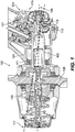
Fig. 1 is a cross-sectional schematic view of an embodiment of a ram air turbine (RAT) in accordance with this disclosure. - Reference will now be made to the drawings wherein like reference numerals identify similar structural features or aspects of the subject disclosure. For purposes of explanation and illustration, and not limitation, an illustrative view of an embodiment of a ram air turbine (RAT) in accordance with the disclosure is shown in
Fig. 1 and is designated generally byreference character 100. Certain embodiments described herein can be used to reduce or eliminate RAT whirl. - A ram air turbine (RAT) 100 can include a
housing 101 and aturbine shaft 103 configured to connect to one ormore turbine blades 105 and be turned by the one ormore blades 105. Theturbine shaft 103 can be disposed in thehousing 101 to rotate relative to thehousing 101 along arotational axis 109. TheRAT turbine 100 can include a first bearing 111 and a second bearing 113 mounted between theturbine shaft 103 and thehousing 101 to allow theturbine shaft 103 to rotate relative to thehousing 101. TheRAT turbine 100 can include awhirl reduction system 115 configured to dampen or eliminate whirl (e.g., orbiting aroundaxis 109 up to whirl extent 117) around therotational axis 109. - The
whirl reduction system 115 can include a third bearing 119 between thehousing 101 and theturbine shaft 103. Thewhirl reduction system 115 can include aspring 121 connected to the third bearing 119 and to thehousing 101 to provide a spring force to theturbine shaft 103 to bias theturbine shaft 103 toward awhirl extent 117, e.g., to limit whirl. Thespring 121 can be selected to provide any suitable force (e.g., enough to hold theturbine shaft 103 in the whirl extent under all loading conditions to eliminate whirl). - In certain embodiments, the
whirl reduction system 115 can include adamper 123, e.g., connected to the third bearing 119 and thehousing 101 to provide damping to theturbine shaft 103. In certain embodiments, thedamper 123 can be connected to the third bearing 119 and thehousing 101 with thespring 121. It is contemplated that thedamper 123 can be in any other suitable location (e.g., a separate bearing), and/or can be used without aspring 121. - In certain embodiments, the third bearing 119 can be positioned aft of both of the first bearing 111 and the second bearing 113, e.g., as shown (e.g., at the end of shaft to provide maximum moment arm to reduce the size of the
spring 121 and/or damper 123). Any other suitable position (e.g., forward of both first andsecond bearings 111, 113), e.g., anywhere along the turbine axis, is contemplated herein. In certain embodiments, a third bearing 119 (e.g., placed at a middle point between the first andsecond bearings 111, 113) can be used alone without aspring 121 ordamper 123, for example. - A center of
gravity 125 of theRAT turbine 100 can be forward of both of the first bearing 111 and the second bearing 119. Any other suitable position for the center ofgravity 125 of theRAT turbine 100 is contemplated herein. - In accordance with at least one aspect of this disclosure, an aircraft can include any suitable ram air turbine (RAT) (e.g., RAT turbine 100) disclosed herein (e.g., as described above). Any other suitable RAT for an aircraft is contemplated herein.
- In accordance with at least one aspect of this disclosure, a method for reducing whirl of a ram air turbine (RAT) can include providing a spring force and/or damping between a turbine shaft and housing to dampen and/or eliminate whirl of the RAT. Providing a spring force and/or damping can include providing both a spring force and damping. Providing a spring force can include providing a sufficient spring force to maintain a whirl extent under all loading conditions in flight. Damping the whirl can include reducing a whirl extent. Reducing a whirl extent can include changing a whirl orbit shape about a rotational axis.
- In traditional RAT designs, the turbine driveshaft rides on two ball bearings. Each ball bearing has radial clearance, due to internal radial clearance, bearing to driveshaft clearance, bearing to liner clearance, etc. This causes the turbine cg (center of gravity) to whirl as it spins. The whirling of the turbine cg creates a rotating load at each of the bearings which is seen by the RAT structure as an oscillating load which can excite natural frequencies in the RAT creating high loads that the RAT structure and the aircraft must survive and can contribute to driveline torque ripple which can be damaging to the RAT.
- Embodiments disclosed herein can include a third bearing added to the turbine driveshaft which mounts to the RAT structure with tuned stiffness and damping characteristics to reduce or eliminate the amount of whirl of the driveshaft. Reducing any rotating load can reduce engineering analysis time, test time, test failures, and result in a lower weight RAT. Certain embodiments can reduce the whirl by restricting radial movement of the shaft. For example, if a third bearing is in the middle if the two existing bearings, this will prevent the shaft from bending. If the third bearing is placed next to either of the bearings, the third bearing, and whichever bearing it is placed next to, will be able to react a moment thereby reducing the potential for the shaft to deflect. Additionally or alternatively, a damper and/or spring can be added to reduce the rotating load due to any remaining whirl.
- Those having ordinary skill in the art understand that any numerical values disclosed herein can be exact values or can be values within a range. Further, any terms of approximation (e.g., "about", "approximately", "around") used in this disclosure can mean the stated value within a range. For example, in certain embodiments, the range can be within (plus or minus) 20%, or within 10%, or within 5%, or within 2%, or within any other suitable percentage or number as appreciated by those having ordinary skill in the art (e.g., for known tolerance limits or error ranges).
- Any suitable combination(s) of any disclosed embodiments and/or any suitable portion(s) thereof are contemplated herein as appreciated by those having ordinary skill in the art.
- The embodiments of the present disclosure, as described above and shown in the drawings, provide for improvement in the art to which they pertain. While the subject disclosure includes reference to certain embodiments, those skilled in the art will readily appreciate that changes and/or modifications may be made thereto without departing from the scope of the invention as defined by the claims.
Claims (13)
- A ram air turbine, RAT, comprising:a housing (101);a turbine shaft (103) configured to connect to one or more turbine blades and be turned by the one or more blades (105), the turbine shaft disposed in the housing to rotate relative to the housing along a rotational axis;a first bearing (111) and a second bearing (113) mounted between the turbine shaft and the housing to allow the turbine shaft to rotate relative to the housing; anda whirl (115) reduction system configured to dampen or eliminate whirl around the rotational axis.
- The RAT of claim 1, wherein the whirl reduction system includes a third bearing (119) between the housing and the turbine shaft.
- The RAT of claim 2, wherein the whirl reduction system includes a spring (121) connected to the third bearing and to the housing to provide a spring force to the turbine shaft to bias the turbine shaft toward a whirl extent.
- The RAT of claim 2, wherein the whirl reduction system includes damper (123) connected to the third bearing and the housing.
- The RAT of claim 3, wherein the whirl reduction system includes damper (123) connected to the third bearing and the housing with the spring.
- The RAT of claim 3, wherein the third bearing is aft of both of the first bearing and the second bearing.
- The RAT of claim 6, wherein a center of gravity of the RAT is forward of both of the first bearing and the second bearing.
- An aircraft, comprising:
a ram air turbine, RAT (100), as claimed in any preceding claim. - A method for reducing whirl of a ram air turbine, RAT, comprising:
providing a spring force and/or damping between a turbine shaft and housing to dampen and/or eliminate whirl of the RAT. - The method of claim 9, wherein providing a spring force and/or damping includes providing both a spring force and damping.
- The method of claim 10, wherein providing a spring force includes providing a sufficient spring force to maintain a whirl extent under all loading conditions in flight.
- The method of claim 11, wherein damping the whirl includes reducing a whirl extent.
- The method of claim 12, wherein reducing a whirl extent includes changing a whirl orbit shape about a rotational axis.
Applications Claiming Priority (1)
| Application Number | Priority Date | Filing Date | Title |
|---|---|---|---|
| US16/363,987 US11022099B2 (en) | 2019-03-25 | 2019-03-25 | Ram air turbine shaft whirl damper |
Publications (2)
| Publication Number | Publication Date |
|---|---|
| EP3715262A1 true EP3715262A1 (en) | 2020-09-30 |
| EP3715262B1 EP3715262B1 (en) | 2026-04-15 |
Family
ID=68581433
Family Applications (1)
| Application Number | Title | Priority Date | Filing Date |
|---|---|---|---|
| EP19208897.9A Active EP3715262B1 (en) | 2019-03-25 | 2019-11-13 | Ram air turbine shaft whirl damper |
Country Status (2)
| Country | Link |
|---|---|
| US (1) | US11022099B2 (en) |
| EP (1) | EP3715262B1 (en) |
Families Citing this family (1)
| Publication number | Priority date | Publication date | Assignee | Title |
|---|---|---|---|---|
| US11603212B1 (en) * | 2021-11-04 | 2023-03-14 | Hamilton Sundstrand Corporation | Strut with inner damper rod |
Citations (5)
| Publication number | Priority date | Publication date | Assignee | Title |
|---|---|---|---|---|
| US4952076A (en) * | 1989-07-21 | 1990-08-28 | United Technologies Corporation | Fluid damper for thrust bearing |
| EP0712996A1 (en) * | 1994-11-18 | 1996-05-22 | AlliedSignal Inc. | In-line ram air turbine power system |
| US20050276530A1 (en) * | 2004-06-15 | 2005-12-15 | Honeywell International Inc. | Composite resilient mount |
| EP1975429A2 (en) * | 2007-03-27 | 2008-10-01 | Honeywell International Inc. | Support dampers for bearing assemblies and methods of manufacture |
| US20120269616A1 (en) * | 2011-04-19 | 2012-10-25 | Hamilton Sundstrand Corporation | Turbine driveshaft for ram air turbine |
Family Cites Families (1)
| Publication number | Priority date | Publication date | Assignee | Title |
|---|---|---|---|---|
| US5505587A (en) | 1995-01-05 | 1996-04-09 | Northrop Grumman Corporation | RAM air turbine generating apparatus |
-
2019
- 2019-03-25 US US16/363,987 patent/US11022099B2/en active Active
- 2019-11-13 EP EP19208897.9A patent/EP3715262B1/en active Active
Patent Citations (5)
| Publication number | Priority date | Publication date | Assignee | Title |
|---|---|---|---|---|
| US4952076A (en) * | 1989-07-21 | 1990-08-28 | United Technologies Corporation | Fluid damper for thrust bearing |
| EP0712996A1 (en) * | 1994-11-18 | 1996-05-22 | AlliedSignal Inc. | In-line ram air turbine power system |
| US20050276530A1 (en) * | 2004-06-15 | 2005-12-15 | Honeywell International Inc. | Composite resilient mount |
| EP1975429A2 (en) * | 2007-03-27 | 2008-10-01 | Honeywell International Inc. | Support dampers for bearing assemblies and methods of manufacture |
| US20120269616A1 (en) * | 2011-04-19 | 2012-10-25 | Hamilton Sundstrand Corporation | Turbine driveshaft for ram air turbine |
Also Published As
| Publication number | Publication date |
|---|---|
| EP3715262B1 (en) | 2026-04-15 |
| US11022099B2 (en) | 2021-06-01 |
| US20200309091A1 (en) | 2020-10-01 |
Similar Documents
| Publication | Publication Date | Title |
|---|---|---|
| US9341116B2 (en) | Gas turbine engine comprising means for axially retaining a fan of the engine | |
| US4695220A (en) | Actuator for variable vanes | |
| US5163817A (en) | Rotor blade retention | |
| DE3124462C2 (en) | Rotor-shaft arrangement for the fan of a gas turbine engine | |
| US8322991B2 (en) | Balance weight | |
| EP2340997B1 (en) | Vibration damping mechanism and aircraft with a support structure and a rotor with such a mechanism | |
| US10197102B2 (en) | Load reduction assemblies for a gas turbine engine | |
| TWI583864B (en) | Gas turbine engines including broadband damping systems and methods for producing the same | |
| GB2080486A (en) | Shafts | |
| US8262353B2 (en) | Decoupler system for rotor assemblies | |
| JP4203473B2 (en) | Rotor re-centering after decoupling | |
| EP1631734B1 (en) | Rotor for a gas turbine | |
| US5017092A (en) | Rotor blade retention | |
| US20160305490A1 (en) | Shaft assembly comprising a frangible coupling and a flexible coupling | |
| DE102014220317A1 (en) | Aircraft gas turbine engine with shock absorbing element for fan blade loss | |
| US10295042B2 (en) | Tuned RAT driveshaft | |
| US11022099B2 (en) | Ram air turbine shaft whirl damper | |
| US9341215B2 (en) | Bearing cage with a peripheral vibration damping ring | |
| EP2546460A2 (en) | Turbine engine and load reduction device thereof | |
| EP3428070A1 (en) | Ram air turbine blades | |
| US7581929B2 (en) | Rotational airfoil balance system | |
| CN110005479B (en) | Aeroengine and fusing load reduction structure for supporting low-voltage rotor bearing thereof | |
| EP3882492A1 (en) | Ram air turbine gearbox assembly | |
| EP3633146B1 (en) | Ram air turbine single-unit nose | |
| CN110206647B (en) | Aeroengine bearing support subassembly and aeroengine |
Legal Events
| Date | Code | Title | Description |
|---|---|---|---|
| PUAI | Public reference made under article 153(3) epc to a published international application that has entered the european phase |
Free format text: ORIGINAL CODE: 0009012 |
|
| STAA | Information on the status of an ep patent application or granted ep patent |
Free format text: STATUS: THE APPLICATION HAS BEEN PUBLISHED |
|
| AK | Designated contracting states |
Kind code of ref document: A1 Designated state(s): AL AT BE BG CH CY CZ DE DK EE ES FI FR GB GR HR HU IE IS IT LI LT LU LV MC MK MT NL NO PL PT RO RS SE SI SK SM TR |
|
| AX | Request for extension of the european patent |
Extension state: BA ME |
|
| STAA | Information on the status of an ep patent application or granted ep patent |
Free format text: STATUS: REQUEST FOR EXAMINATION WAS MADE |
|
| 17P | Request for examination filed |
Effective date: 20210330 |
|
| RBV | Designated contracting states (corrected) |
Designated state(s): AL AT BE BG CH CY CZ DE DK EE ES FI FR GB GR HR HU IE IS IT LI LT LU LV MC MK MT NL NO PL PT RO RS SE SI SK SM TR |
|
| STAA | Information on the status of an ep patent application or granted ep patent |
Free format text: STATUS: EXAMINATION IS IN PROGRESS |
|
| 17Q | First examination report despatched |
Effective date: 20220223 |
|
| REG | Reference to a national code |
Ref country code: DE Ref legal event code: R079 Free format text: PREVIOUS MAIN CLASS: B64D0041000000 Ipc: F01D0005100000 Ref country code: DE Ref legal event code: R079 Ref document number: 602019083624 Country of ref document: DE Free format text: PREVIOUS MAIN CLASS: B64D0041000000 Ipc: F01D0005100000 |
|
| GRAP | Despatch of communication of intention to grant a patent |
Free format text: ORIGINAL CODE: EPIDOSNIGR1 |
|
| STAA | Information on the status of an ep patent application or granted ep patent |
Free format text: STATUS: GRANT OF PATENT IS INTENDED |
|
| RIC1 | Information provided on ipc code assigned before grant |
Ipc: F01D 5/10 20060101AFI20250730BHEP Ipc: F01D 25/16 20060101ALI20250730BHEP Ipc: B64D 41/00 20060101ALI20250730BHEP Ipc: F01D 15/10 20060101ALI20250730BHEP Ipc: F01D 5/02 20060101ALI20250730BHEP |
|
| INTG | Intention to grant announced |
Effective date: 20250808 |
|
| GRAJ | Information related to disapproval of communication of intention to grant by the applicant or resumption of examination proceedings by the epo deleted |
Free format text: ORIGINAL CODE: EPIDOSDIGR1 |
|
| STAA | Information on the status of an ep patent application or granted ep patent |
Free format text: STATUS: EXAMINATION IS IN PROGRESS |
|
| GRAP | Despatch of communication of intention to grant a patent |
Free format text: ORIGINAL CODE: EPIDOSNIGR1 |
|
| STAA | Information on the status of an ep patent application or granted ep patent |
Free format text: STATUS: GRANT OF PATENT IS INTENDED |
|
| INTC | Intention to grant announced (deleted) | ||
| INTG | Intention to grant announced |
Effective date: 20251219 |
|
| GRAS | Grant fee paid |
Free format text: ORIGINAL CODE: EPIDOSNIGR3 |
|
| GRAA | (expected) grant |
Free format text: ORIGINAL CODE: 0009210 |
|
| STAA | Information on the status of an ep patent application or granted ep patent |
Free format text: STATUS: THE PATENT HAS BEEN GRANTED |
|
| AK | Designated contracting states |
Kind code of ref document: B1 Designated state(s): AL AT BE BG CH CY CZ DE DK EE ES FI FR GB GR HR HU IE IS IT LI LT LU LV MC MK MT NL NO PL PT RO RS SE SI SK SM TR |
|
| REG | Reference to a national code |
Ref country code: CH Ref legal event code: F10 Free format text: ST27 STATUS EVENT CODE: U-0-0-F10-F00 (AS PROVIDED BY THE NATIONAL OFFICE) Effective date: 20260415 Ref country code: GB Ref legal event code: FG4D |
|
| REG | Reference to a national code |
Ref country code: DE Ref legal event code: R096 Ref document number: 602019083624 Country of ref document: DE |