EP3715241A1 - A stiffened structural component for an aircraft - Google Patents
A stiffened structural component for an aircraft Download PDFInfo
- Publication number
- EP3715241A1 EP3715241A1 EP19165843.4A EP19165843A EP3715241A1 EP 3715241 A1 EP3715241 A1 EP 3715241A1 EP 19165843 A EP19165843 A EP 19165843A EP 3715241 A1 EP3715241 A1 EP 3715241A1
- Authority
- EP
- European Patent Office
- Prior art keywords
- structural component
- bulges
- material sheet
- component
- aircraft
- Prior art date
- Legal status (The legal status is an assumption and is not a legal conclusion. Google has not performed a legal analysis and makes no representation as to the accuracy of the status listed.)
- Withdrawn
Links
- 239000000463 material Substances 0.000 claims abstract description 102
- 238000003825 pressing Methods 0.000 claims abstract description 17
- 238000000034 method Methods 0.000 claims description 17
- 230000008569 process Effects 0.000 claims description 15
- 238000001556 precipitation Methods 0.000 claims description 5
- RZVHIXYEVGDQDX-UHFFFAOYSA-N 9,10-anthraquinone Chemical group C1=CC=C2C(=O)C3=CC=CC=C3C(=O)C2=C1 RZVHIXYEVGDQDX-UHFFFAOYSA-N 0.000 claims description 3
- 239000007769 metal material Substances 0.000 description 12
- 238000004519 manufacturing process Methods 0.000 description 9
- 229910000838 Al alloy Inorganic materials 0.000 description 6
- 239000007767 bonding agent Substances 0.000 description 5
- 239000000835 fiber Substances 0.000 description 3
- 238000009434 installation Methods 0.000 description 3
- 239000004033 plastic Substances 0.000 description 3
- 229920003023 plastic Polymers 0.000 description 3
- 238000001953 recrystallisation Methods 0.000 description 3
- 239000012815 thermoplastic material Substances 0.000 description 3
- 229910000831 Steel Inorganic materials 0.000 description 2
- 229910052782 aluminium Inorganic materials 0.000 description 2
- XAGFODPZIPBFFR-UHFFFAOYSA-N aluminium Chemical compound [Al] XAGFODPZIPBFFR-UHFFFAOYSA-N 0.000 description 2
- 230000008901 benefit Effects 0.000 description 2
- 238000010438 heat treatment Methods 0.000 description 2
- 239000003562 lightweight material Substances 0.000 description 2
- 229910052751 metal Inorganic materials 0.000 description 2
- 239000002184 metal Substances 0.000 description 2
- 239000000203 mixture Substances 0.000 description 2
- 239000010959 steel Substances 0.000 description 2
- 239000004696 Poly ether ether ketone Substances 0.000 description 1
- 239000004952 Polyamide Substances 0.000 description 1
- 239000004697 Polyetherimide Substances 0.000 description 1
- RTAQQCXQSZGOHL-UHFFFAOYSA-N Titanium Chemical compound [Ti] RTAQQCXQSZGOHL-UHFFFAOYSA-N 0.000 description 1
- 238000004026 adhesive bonding Methods 0.000 description 1
- 229910045601 alloy Inorganic materials 0.000 description 1
- 239000000956 alloy Substances 0.000 description 1
- 238000000137 annealing Methods 0.000 description 1
- 230000009286 beneficial effect Effects 0.000 description 1
- JUPQTSLXMOCDHR-UHFFFAOYSA-N benzene-1,4-diol;bis(4-fluorophenyl)methanone Chemical compound OC1=CC=C(O)C=C1.C1=CC(F)=CC=C1C(=O)C1=CC=C(F)C=C1 JUPQTSLXMOCDHR-UHFFFAOYSA-N 0.000 description 1
- 238000009833 condensation Methods 0.000 description 1
- 230000005494 condensation Effects 0.000 description 1
- 239000000109 continuous material Substances 0.000 description 1
- 230000003247 decreasing effect Effects 0.000 description 1
- 238000009826 distribution Methods 0.000 description 1
- 230000000694 effects Effects 0.000 description 1
- 239000006260 foam Substances 0.000 description 1
- 239000003292 glue Substances 0.000 description 1
- 230000001788 irregular Effects 0.000 description 1
- 238000004021 metal welding Methods 0.000 description 1
- 150000002739 metals Chemical class 0.000 description 1
- 238000005457 optimization Methods 0.000 description 1
- 229920001652 poly(etherketoneketone) Polymers 0.000 description 1
- 229920002647 polyamide Polymers 0.000 description 1
- 229920006260 polyaryletherketone Polymers 0.000 description 1
- 229920002530 polyetherether ketone Polymers 0.000 description 1
- 229920001601 polyetherimide Polymers 0.000 description 1
- 229920000069 polyphenylene sulfide Polymers 0.000 description 1
- 230000009467 reduction Effects 0.000 description 1
- 230000002787 reinforcement Effects 0.000 description 1
- 229920001169 thermoplastic Polymers 0.000 description 1
- 239000004416 thermosoftening plastic Substances 0.000 description 1
- 239000010936 titanium Substances 0.000 description 1
- 229910052719 titanium Inorganic materials 0.000 description 1
- 230000007704 transition Effects 0.000 description 1
- XLYOFNOQVPJJNP-UHFFFAOYSA-N water Substances O XLYOFNOQVPJJNP-UHFFFAOYSA-N 0.000 description 1
Images



Classifications
-
- B—PERFORMING OPERATIONS; TRANSPORTING
- B64—AIRCRAFT; AVIATION; COSMONAUTICS
- B64F—GROUND OR AIRCRAFT-CARRIER-DECK INSTALLATIONS SPECIALLY ADAPTED FOR USE IN CONNECTION WITH AIRCRAFT; DESIGNING, MANUFACTURING, ASSEMBLING, CLEANING, MAINTAINING OR REPAIRING AIRCRAFT, NOT OTHERWISE PROVIDED FOR; HANDLING, TRANSPORTING, TESTING OR INSPECTING AIRCRAFT COMPONENTS, NOT OTHERWISE PROVIDED FOR
- B64F5/00—Designing, manufacturing, assembling, cleaning, maintaining or repairing aircraft, not otherwise provided for; Handling, transporting, testing or inspecting aircraft components, not otherwise provided for
-
- B—PERFORMING OPERATIONS; TRANSPORTING
- B32—LAYERED PRODUCTS
- B32B—LAYERED PRODUCTS, i.e. PRODUCTS BUILT-UP OF STRATA OF FLAT OR NON-FLAT, e.g. CELLULAR OR HONEYCOMB, FORM
- B32B15/00—Layered products comprising a layer of metal
-
- B—PERFORMING OPERATIONS; TRANSPORTING
- B32—LAYERED PRODUCTS
- B32B—LAYERED PRODUCTS, i.e. PRODUCTS BUILT-UP OF STRATA OF FLAT OR NON-FLAT, e.g. CELLULAR OR HONEYCOMB, FORM
- B32B27/00—Layered products comprising a layer of synthetic resin
-
- B—PERFORMING OPERATIONS; TRANSPORTING
- B32—LAYERED PRODUCTS
- B32B—LAYERED PRODUCTS, i.e. PRODUCTS BUILT-UP OF STRATA OF FLAT OR NON-FLAT, e.g. CELLULAR OR HONEYCOMB, FORM
- B32B3/00—Layered products comprising a layer with external or internal discontinuities or unevennesses, or a layer of non-planar shape; Layered products comprising a layer having particular features of form
- B32B3/26—Layered products comprising a layer with external or internal discontinuities or unevennesses, or a layer of non-planar shape; Layered products comprising a layer having particular features of form characterised by a particular shape of the outline of the cross-section of a continuous layer; characterised by a layer with cavities or internal voids ; characterised by an apertured layer
- B32B3/28—Layered products comprising a layer with external or internal discontinuities or unevennesses, or a layer of non-planar shape; Layered products comprising a layer having particular features of form characterised by a particular shape of the outline of the cross-section of a continuous layer; characterised by a layer with cavities or internal voids ; characterised by an apertured layer characterised by a layer comprising a deformed thin sheet, i.e. the layer having its entire thickness deformed out of the plane, e.g. corrugated, crumpled
-
- B—PERFORMING OPERATIONS; TRANSPORTING
- B64—AIRCRAFT; AVIATION; COSMONAUTICS
- B64C—AEROPLANES; HELICOPTERS
- B64C1/00—Fuselages; Constructional features common to fuselages, wings, stabilising surfaces or the like
-
- B—PERFORMING OPERATIONS; TRANSPORTING
- B64—AIRCRAFT; AVIATION; COSMONAUTICS
- B64C—AEROPLANES; HELICOPTERS
- B64C1/00—Fuselages; Constructional features common to fuselages, wings, stabilising surfaces or the like
- B64C1/06—Frames; Stringers; Longerons ; Fuselage sections
- B64C1/061—Frames
-
- B—PERFORMING OPERATIONS; TRANSPORTING
- B64—AIRCRAFT; AVIATION; COSMONAUTICS
- B64C—AEROPLANES; HELICOPTERS
- B64C1/00—Fuselages; Constructional features common to fuselages, wings, stabilising surfaces or the like
- B64C1/06—Frames; Stringers; Longerons ; Fuselage sections
- B64C1/064—Stringers; Longerons
-
- B—PERFORMING OPERATIONS; TRANSPORTING
- B64—AIRCRAFT; AVIATION; COSMONAUTICS
- B64C—AEROPLANES; HELICOPTERS
- B64C1/00—Fuselages; Constructional features common to fuselages, wings, stabilising surfaces or the like
- B64C1/06—Frames; Stringers; Longerons ; Fuselage sections
- B64C1/10—Bulkheads
-
- B—PERFORMING OPERATIONS; TRANSPORTING
- B64—AIRCRAFT; AVIATION; COSMONAUTICS
- B64C—AEROPLANES; HELICOPTERS
- B64C1/00—Fuselages; Constructional features common to fuselages, wings, stabilising surfaces or the like
- B64C1/06—Frames; Stringers; Longerons ; Fuselage sections
- B64C1/12—Construction or attachment of skin panels
-
- B—PERFORMING OPERATIONS; TRANSPORTING
- B64—AIRCRAFT; AVIATION; COSMONAUTICS
- B64C—AEROPLANES; HELICOPTERS
- B64C1/00—Fuselages; Constructional features common to fuselages, wings, stabilising surfaces or the like
- B64C1/18—Floors
-
- B—PERFORMING OPERATIONS; TRANSPORTING
- B32—LAYERED PRODUCTS
- B32B—LAYERED PRODUCTS, i.e. PRODUCTS BUILT-UP OF STRATA OF FLAT OR NON-FLAT, e.g. CELLULAR OR HONEYCOMB, FORM
- B32B2605/00—Vehicles
- B32B2605/18—Aircraft
-
- B—PERFORMING OPERATIONS; TRANSPORTING
- B64—AIRCRAFT; AVIATION; COSMONAUTICS
- B64C—AEROPLANES; HELICOPTERS
- B64C1/00—Fuselages; Constructional features common to fuselages, wings, stabilising surfaces or the like
- B64C2001/0054—Fuselage structures substantially made from particular materials
-
- B—PERFORMING OPERATIONS; TRANSPORTING
- B64—AIRCRAFT; AVIATION; COSMONAUTICS
- B64C—AEROPLANES; HELICOPTERS
- B64C3/00—Wings
- B64C3/26—Construction, shape, or attachment of separate skins, e.g. panels
-
- B—PERFORMING OPERATIONS; TRANSPORTING
- B64—AIRCRAFT; AVIATION; COSMONAUTICS
- B64C—AEROPLANES; HELICOPTERS
- B64C5/00—Stabilising surfaces
- B64C5/02—Tailplanes
-
- B—PERFORMING OPERATIONS; TRANSPORTING
- B64—AIRCRAFT; AVIATION; COSMONAUTICS
- B64F—GROUND OR AIRCRAFT-CARRIER-DECK INSTALLATIONS SPECIALLY ADAPTED FOR USE IN CONNECTION WITH AIRCRAFT; DESIGNING, MANUFACTURING, ASSEMBLING, CLEANING, MAINTAINING OR REPAIRING AIRCRAFT, NOT OTHERWISE PROVIDED FOR; HANDLING, TRANSPORTING, TESTING OR INSPECTING AIRCRAFT COMPONENTS, NOT OTHERWISE PROVIDED FOR
- B64F5/00—Designing, manufacturing, assembling, cleaning, maintaining or repairing aircraft, not otherwise provided for; Handling, transporting, testing or inspecting aircraft components, not otherwise provided for
- B64F5/10—Manufacturing or assembling aircraft, e.g. jigs therefor
Definitions
- the invention relates to a stiffened structural component for an aircraft as well as an aircraft having such a stiffened structural component.
- fuselage skin components of an aircraft often comprise a sheet-like skin, to which a plurality of stringers are attached that commonly extend along the longitudinal axis of the aircraft.
- the stringers may be bonded, welded or riveted to the skin.
- the stringers usually comprise a curved profile and a base surface, which conforms the shape of the skin. The manufacturing process thus requires producing a plurality of stringers, their correct placement and an appropriate bonding or connection.
- US20040075023A1 shows a lightweight, laminated structural component, such as a skin section for an aircraft fuselage, which is constructed of at least two sheet metal plies that are adhesively bonded to each other. One of the plies is uninterrupted, while the other ply is a lattice with open fields surrounded by strip shaped lands.
- a stiffened structural component for an aircraft comprising a first material sheet with a first surface, and at least one elongate bulge that bulges out in a direction transverse to the first surface in order to stiffen the structural component, wherein each of the at least one bulge comprises two edges that extend along the first surface, wherein a continuous bulging surface extends between the edges, and wherein the bulges are formed integrally into the first material sheet through pressing.
- the structural component may be considered a component that is subjected to a substantial mechanical load, which is to be absorbed by the structural component.
- the structural component may be a substantial mechanical part of the aircraft, which may either define the shape of at least a part of the aircraft or that bears a substantial mechanical load that arises during the operation of the aircraft.
- a skin component, a frame, a wing shell, a pressure bulkhead or other components may be considered.
- the structural component is mainly defined by the first material sheet.
- the first material sheet is to be understood a sheet-like continuous part made from a certain material.
- the shape of the first material sheet can be arbitrarily selected.
- the first material sheet is a continuous sheet of a constant thickness, at least as a starting point of a process for manufacturing the structural component.
- certain different materials may be considered for providing the first material sheet.
- metallic materials such as various types of steel, aluminum alloys or other metallic materials that provide satisfying mechanical properties for the desired task of the structural component.
- plastic materials and particularly thermoplastic materials may be considered, which allow a press-forming of the bulges. These may include, for example, Polyamide, Polyetherimide, PEKK, PEEK, PAEK, PPS or other suitable materials.
- a mixture of different materials, such as different metals, different plastic materials or even a mixed use of metallic and plastic materials may in some cases be beneficial.
- All materials may optionally comprise embedded reinforcement fibers, wherein short fibers may particularly be more suitable for press-forming than long fibers.
- a gist of the invention lies in the at least one elongate bulge that bulges out in a direction transverse to the first surface.
- the bulge may comprise a certain hollow profile, which is provided through pressing a section of the first material sheet into the direction transverse to the first surface. Consequently, separately manufactured parts for attachment to the first material sheet are not required.
- a corrugated material sheet is produced. Manufacturing such a corrugated sheet can be done by roll forming or any other feasible process which would, for example, reduce the number of individually manufactured stringers. The assembly lead times are also reduced by a large margin from this by eliminating individual assembly of stringers with a single corrugated sheet. This also comprises a higher structural stability due to the hollow profiles of the bulges.
- the bulge is to be understood as a continuous surface section that extends out of the first surface transversely to a main extension plane.
- a bulge is formed by pressing a certain surface section in the first surface into the transverse direction by using a pressing tool.
- the surface section is thus deformed to extend out of the neighboring first surface area to constitute the bulging surface.
- the bulging surface is continuous and preferably uninterrupted.
- at least two delimiting edges are created just between the bulging surface and the first surface.
- the at least two edges can be considered foot or base lines between the bulging surface and the first surface.
- the bulging surface extends from the at least two edges into the transverse direction.
- the structural component according to the invention only requires a reduced number of parts to be assembled and reduce lead times of manufacturing and assembly of an aircraft structure.
- the component comprises a plurality of bulges that are arranged at a distance to each other.
- the bulges may preferably comprise the same profiles, i.e. the same shape of a cross section perpendicular to a main extension axis of the bulges. They may also be arranged in a pattern or on a grid on the first surface that may preferably be regular at least in a region or that may be irregular. For stiffening a rather large surface area it may be feasible to provide a plurality of linear or longitudinal bulges and that are parallel to each other.
- the bulging surface comprises a symmetric hollow profile. It may be selected from a group of different profile shapes, the group comprising omega, rectangular, square, triangular, parallelogram, half circle and other chamfered or round profile shapes.
- a symmetrical profile By using such a symmetrical profile, a symmetric load distribution can be achieved. If the clear span between opposed flanks of the profile shape does not decrease in an outward direction, i.e. away from the first surface, manufacturing the bulges is simplified, as the pressing tool may easily be removed from bulges after they have been pressed.
- the bulges are arranged on the first surface in a regular pattern.
- the pattern may include at least a group of bulges that are arranged parallel to each other and having the same distances to each other at least in a region of the first surface. It may be possible to use a single, two or more such groups. It may also be feasible to let the bulges of different groups extend into different directions. It may also be possible to use different distances between the bulges of two different groups of bulges.
- the bulges comprise a height in a range of 3 to 50 mm. Selecting a suitable height allows to achieve a sufficient stability by providing a sufficient increase of the moment of inertia in the desired direction. Thus, depending on the structural loads on the respective component, the height may be more in the region of 3 mm or more in the region of 50 mm. However, a height of 50 mm is clearly tolerable for many different designs of stiffened components.
- the first material sheet is made from a metallic material.
- the metallic material may comprise one from a variety of different aluminum alloys, different types of steel, titanium or other metallic materials suitable for the respective task of the component. Depending on the pressing tool and pressing method a certain metallic material may be preferred over others.
- the material of the first material sheet is not precipitation hardenable. Hence, in particular with a hot forming process, the desired mechanical properties can be maintained.
- the metallic material of the first material sheet comprises a 5000-series aluminum alloy. If the bulges are formed by a hot forming process, the respective first material sheet needs to be heated to a temperature that leads to a sufficient softening of the material that allows the hot forming.
- Aluminum alloy may exemplarily be heated to a temperature of about 300°C.
- a 5000 series aluminum alloy may be suitable, since it is not precipitation hardenable. This means that the mechanical integrity of the first material sheet will not be reduced through the process of heating and subsequent forming.
- other materials such as other alloys or thermoplastic materials, other boundary conditions and requirements must be met.
- the bulges are formed by a hot forming process.
- Hot forming or hot working stands for plastically deforming of the first material sheet that has an elevated temperature. If the first material sheet comprises a metallic material, the temperature to which it is heated before being deformed may exceed a recrystallization temperature, which allows a recrystallization after the deforming process and prevents the component from being strain hardened.
- Precipitation hardenable metallic materials do not seem to be a suitable basis for the first material sheet, as the hardening would need to be reverted through a solution annealing. Thus, a 5000-series aluminum would be more suitable for the process of hot forming than a 6000 serious aluminum, which is precipitation hardenable. This applies in analogy to other metallic materials.
- the structural component may further comprise a second material sheet, which is attached to the second surface of the first material sheet.
- the second material sheet together with the first material sheet provides an integral component, which may then comprise a closed surface on one side and the appearance of a corrugated sheet on the other side, depending on the number of bulges.
- this arrangement allows the component to be a part of an aerodynamic surface, such as a fuselage skin, a wing shell, a part of the tail plane or other surfaces that are exposed to a direct airflow.
- the second material sheet is attached to the first material sheet through material bonding.
- the second material sheet is thus glued or welded to the first material sheet. If both materials sheets are made from a metallic material, gluing may be a feasible approach to prevent local deformations due to heat strains. If material sheets from a thermoplastics material are used, they may be welded, as heat strains may be limited compared to the welding of metals. By materially bonding both material sheets, a smooth and very harmonic design may be achieved.
- the first material sheet comprises at least one cutout between at least two bulges.
- cutouts lead to a distinct reduction of weight.
- a plurality of cutouts is formed in the first material sheet and extends in a free space between neighboring bulges.
- the flat surface regions may be flushly arranged on the second material sheet. In these regions, mechanical connection elements extending through both material sheets or bonding agents can be applied.
- the structural component may further comprise at least one cover plate for covering a bulge on a side opposite the bulging surface.
- the cover plate is able to close an open side of a bulge, such that the second surface is substantially closed.
- the cover plate may be bonded to the second surface to maintain its position. It may be feasible to seal the transition between the second surface and the cover plate to prevent ingress of moisture or water condensation effects.
- the structural component may be selected from a group of structural components, the group consisting of a fuselage skin component, an airframe component, a rear pressure bulkhead, a wing shell, a horizontal tail plane shell, a vertical tail plane shell, floor panels for a cabin of the aircraft, primary or secondary flight control surfaces, movable flow bodies in general.
- a stiffened structural component according to the invention for these purposes, the manufacturing process will be clearly accelerated and simplified, while the total weight is reduced, and the structural stability is maintained, in comparison with common designs of structural components for the given purposes.
- the structural component is a rear pressure bulkhead for a pressurized cabin of an aircraft, the rear pressure bulkhead comprising a plurality of radial bulges distributed around a central region of the rear pressure bulkhead.
- the pressure bulkhead serves for separating a pressurized part of the fuselage from an unpressurized part of the fuselage. It thus needs to be pressure-tight as a whole.
- the bulkhead may comprise a strong curvature around at least one axis. For example, it may comprise a shape similar to a spherical cap. Starting from a planar material sheet, both the curvature and the bulges may be created in a single pressing step.
- the component is a fuselage skin component for a fuselage of an aircraft, the fuselage skin component comprising a plurality of axial bulges arranged parallel and at a distance to each other.
- the bulges may provide the function of longitudinal stiffening elements, i.e. stringers.
- the invention relates to an aircraft having at least one such structural component.
- the at least one structural component may be selected from a group of structural components, the group consisting of a fuselage skin component, an airframe component, a rear pressure bulkhead, a wing shell, a horizontal tail plane shell, a vertical tail plane shell, floor panels for a cabin of the aircraft, primary or secondary flight control surfaces, movable flow bodies in general.
- Fig.1 shows an exemplary embodiment of a stiffened structural component 2 as well as a very schematic illustration of a process for manufacturing the component 2.
- a first material sheet 4 is provided, which comprises a first surface 6 and a second surface 8 on the opposite side.
- a plurality of elongate bulges 10 are provided on the first surface 6, . They are arranged parallel and at a distance to each other.
- the bulges 10 bulge out from the first surface 6 into a direction transverse thereto. In doing so, they increase the moment of inertia around an axis 12, which is schematically shown just for illustration purposes.
- a first section 14 of the first material sheet 4 comprises a plurality of cutouts 16, which are arranged between neighboring bulges 10.
- the cutouts 16 are arranged in a pattern or grid on the first material sheet 4 in order to create several webs 18 and 20 that allow the first material sheet 4 to be flushly laid onto another surface.
- the spaces between neighboring bulges 10 are continuous and do not comprise cutouts 16.
- the first material sheet 4 is created through a pressing process.
- a planar base sheet as a starting point is formed through a pressing tool to not only provide a slight curvature as visible in Fig. 1 , but also a plurality of bulges 10.
- the cutouts 16 may be formed by pressing, too, they may also be machined after or before the press-forming.
- a cold pressing may be conducted, such as a roll forming or a similar method.
- the base sheet is fed into a roll forming tool and by passing through it, the bulges 10 and the curvature are created.
- incremental and magnetic pulse forming processes may be used.
- the base sheet is heated to a certain temperature, that depends on the selected material.
- the material of the first material sheet 4 is a metallic material, heating above a recrystallization temperature is feasible. In the case of aluminum alloy this may be a temperature of about or slightly above 300°C.
- the material may recrystallize, which leads to an improved mechanical stability. If, however, the material is a thermoplastic material, it may be heated to a certain temperature at which the material is clearly softened, but not molten.
- An advantage of a hot forming process is an improved deformability of the material allowing to provide a plurality of different local and global deformations at once, i.e. in a single step. By adjusting the temperature of the material before deforming it, superior mechanical properties are achieved.
- a second material sheet 24 is provided.
- the second material sheet 24 has a similar curvature as the first material sheet 4 but is realized as a continuous material sheet.
- the first material sheet 4 and the second material sheet 24 may be combined to form the stiffened structural component 2.
- a bonding agent can be placed between both material sheets 4 and 24, Due to the cutouts 16 the weight of the structural component 2 is optimized.
- Fig. 2 shows a detailed lateral view of the first material sheet 4 from the direction indicated in Fig. 1 by the letter A.
- the bulges 10 are shown to comprise a symmetric trapezoid shape with a clear span s, which is decreasing with increasing distance from the first surface 6.
- Each of the bulges 10 has a foot region in the form of two opposed edges 26 that are placed just on the first surface 6 and on a bulging surface 28 of the respective bulge 10.
- the edges 26 are arranged at a distance to each other and extend along the first surface 6.
- a substantially flat surface region 30 is present.
- the first material sheet 4 is arranged on the second material sheet 24, wherein both sheets 4 and 24 enclose a bonding agent 32, such as a glue.
- a bonding agent 32 such as a glue.
- both material sheets 4 and 24 are bonded together.
- the bulges 10 provide a stiffening function on one side of the component 2, while the second material sheet 24 provides a continuously closed and smooth surface that is suitable for aircraft components directly exposed to an airflow.
- Fig. 3 shows the structural components 2 as a part of a fuselage structure of an aircraft.
- a part of a circular frame 34 is shown, to which the structure component 2 is attached by using several clips 36.
- the cutouts 16 lead to a reduced effective thickness of a fuselage skin.
- the bulges 10 comprise a common pitch, i.e. a distance between their longitudinal axes, as common stringers. However, due to their structure, they are able to provide an improved moment of inertia.
- Figure 4a, 4b , 4c and 4d show a further stiffened structural component 38 in the form of a rear pressure bulkhead.
- Fig. 4a shows a front view, i.e. the side of the pressure bulkhead that faces to the front of the aircraft and into the pressurized cabin.
- several bulges 40 are radially arranged and distributed around a central region 42. In this example, they are evenly distributed and thus enclose the same angles to each other throughout the pressure bulkhead 38.
- due to certain required installations 44 and 46 they may comprise different lengths or they are partially left out completely.
- Fig. 4c shows the bulges 40 and in a three-dimensional view.
- the pressure bulkhead 38 with its curvature as well as its plurality of bulges 40 may be created in a single manufacturing, i.e. pressing step.
- Fig. 4b shows a rear view of the pressure bulkhead 38 comprising open sides 48 of the bulges 40. They may be closed by cover plates 50 as shown in figure 4d .
- Fig. 5 shows a schematic view of a bonding area between the first material sheet 4 and the second material sheet 24 of the first exemplary embodiment.
- a bonded area 52 includes the bonding agent 32 between both material sheets 4 and 24.
- the bonded area 52 surrounds the cutouts 16.
- Several bulges 10 are arranged parallel and at a distance to each other and extend along the bonded area 52. Exemplarily, they may enclose a surface area 54 that does not comprise cutouts 16 and that is machined for a variable thickness for optimization purposes. The same applies to a surface area 56 between cutouts 16.
- the bulges 10 may be filled with a lightweight material 58 that may be a foam or another material with a low density or may be left completely hollow.
- Fig. 6 shows an aircraft 60 having a fuselage 62, wings 64, a tail plane 66 with a horizontal tail plane 68 and a vertical tail plane 70.
- a rear pressure bulkhead 38 may be placed on a rear side underneath all forward of the tail plane 66.
- the fuselage 62 may comprise at least one component 2 explained above.
- the wings 64 may comprise at least one such stiffened structural component 2.
Landscapes
- Engineering & Computer Science (AREA)
- Aviation & Aerospace Engineering (AREA)
- Mechanical Engineering (AREA)
- Manufacturing & Machinery (AREA)
- Transportation (AREA)
- Laminated Bodies (AREA)
Abstract
A stiffened structural component for an aircraft comprises a first material sheet with a first surface, and at least one elongate bulge that bulges out in a direction transverse to the first surface in order to stiffen the structural component, wherein each of the at least one bulge comprises two edges that extend along the first surface, wherein a continuous bulging surface extends between the edges, and wherein the bulges are formed integrally into the first material sheet through pressing.
Description
- The invention relates to a stiffened structural component for an aircraft as well as an aircraft having such a stiffened structural component.
- Large structural components for transportation means, such as aircraft, are often manufactured by using surface-like components, to which stiffening elements are attached. For example, fuselage skin components of an aircraft often comprise a sheet-like skin, to which a plurality of stringers are attached that commonly extend along the longitudinal axis of the aircraft. The stringers may be bonded, welded or riveted to the skin. The stringers usually comprise a curved profile and a base surface, which conforms the shape of the skin. The manufacturing process thus requires producing a plurality of stringers, their correct placement and an appropriate bonding or connection.
-
US20040075023A1 shows a lightweight, laminated structural component, such as a skin section for an aircraft fuselage, which is constructed of at least two sheet metal plies that are adhesively bonded to each other. One of the plies is uninterrupted, while the other ply is a lattice with open fields surrounded by strip shaped lands., - It is thus an object of the invention to propose a structural component for an aircraft that can be manufactured more simply and that comprises at least the same or even a superior structural stability.
- This object is met by a stiffened structural component for an aircraft having the features of independent claim 1. Advantageous embodiments and further improvements may be gathered from the subclaims and the following description.
- A stiffened structural component for an aircraft is proposed, the component comprising a first material sheet with a first surface, and at least one elongate bulge that bulges out in a direction transverse to the first surface in order to stiffen the structural component, wherein each of the at least one bulge comprises two edges that extend along the first surface, wherein a continuous bulging surface extends between the edges, and wherein the bulges are formed integrally into the first material sheet through pressing.
- The structural component may be considered a component that is subjected to a substantial mechanical load, which is to be absorbed by the structural component. Thus, the structural component may be a substantial mechanical part of the aircraft, which may either define the shape of at least a part of the aircraft or that bears a substantial mechanical load that arises during the operation of the aircraft. As an example, a skin component, a frame, a wing shell, a pressure bulkhead or other components may be considered.
- The structural component is mainly defined by the first material sheet. The first material sheet is to be understood a sheet-like continuous part made from a certain material. The shape of the first material sheet can be arbitrarily selected. For example, the first material sheet is a continuous sheet of a constant thickness, at least as a starting point of a process for manufacturing the structural component.
- As explained in the following, certain different materials may be considered for providing the first material sheet. For example, metallic materials may be used, such as various types of steel, aluminum alloys or other metallic materials that provide satisfying mechanical properties for the desired task of the structural component. However, also plastic materials and particularly thermoplastic materials may be considered, which allow a press-forming of the bulges. These may include, for example, Polyamide, Polyetherimide, PEKK, PEEK, PAEK, PPS or other suitable materials. A mixture of different materials, such as different metals, different plastic materials or even a mixed use of metallic and plastic materials may in some cases be beneficial. All materials may optionally comprise embedded reinforcement fibers, wherein short fibers may particularly be more suitable for press-forming than long fibers.
- A gist of the invention lies in the at least one elongate bulge that bulges out in a direction transverse to the first surface. For allowing an increased moment of inertia about an axis transverse to a main extension line of the bulge and in a distance to the first material sheet, the bulge may comprise a certain hollow profile, which is provided through pressing a section of the first material sheet into the direction transverse to the first surface. Consequently, separately manufactured parts for attachment to the first material sheet are not required. If several bulges are used, a corrugated material sheet is produced. Manufacturing such a corrugated sheet can be done by roll forming or any other feasible process which would, for example, reduce the number of individually manufactured stringers. The assembly lead times are also reduced by a large margin from this by eliminating individual assembly of stringers with a single corrugated sheet. This also comprises a higher structural stability due to the hollow profiles of the bulges.
- The bulge is to be understood as a continuous surface section that extends out of the first surface transversely to a main extension plane. In the context of the invention, such a bulge is formed by pressing a certain surface section in the first surface into the transverse direction by using a pressing tool. The surface section is thus deformed to extend out of the neighboring first surface area to constitute the bulging surface. The bulging surface is continuous and preferably uninterrupted. By bulging out, at least two delimiting edges are created just between the bulging surface and the first surface. The at least two edges can be considered foot or base lines between the bulging surface and the first surface. The bulging surface extends from the at least two edges into the transverse direction.
- To sum up, the structural component according to the invention only requires a reduced number of parts to be assembled and reduce lead times of manufacturing and assembly of an aircraft structure.
- In a preferred embodiment the component comprises a plurality of bulges that are arranged at a distance to each other. The bulges may preferably comprise the same profiles, i.e. the same shape of a cross section perpendicular to a main extension axis of the bulges. They may also be arranged in a pattern or on a grid on the first surface that may preferably be regular at least in a region or that may be irregular. For stiffening a rather large surface area it may be feasible to provide a plurality of linear or longitudinal bulges and that are parallel to each other.
- In an advantageous embodiment, the bulging surface comprises a symmetric hollow profile. It may be selected from a group of different profile shapes, the group comprising omega, rectangular, square, triangular, parallelogram, half circle and other chamfered or round profile shapes. By using such a symmetrical profile, a symmetric load distribution can be achieved. If the clear span between opposed flanks of the profile shape does not decrease in an outward direction, i.e. away from the first surface, manufacturing the bulges is simplified, as the pressing tool may easily be removed from bulges after they have been pressed.
- Still further, in a preferred embodiment the bulges are arranged on the first surface in a regular pattern. The pattern may include at least a group of bulges that are arranged parallel to each other and having the same distances to each other at least in a region of the first surface. It may be possible to use a single, two or more such groups. It may also be feasible to let the bulges of different groups extend into different directions. It may also be possible to use different distances between the bulges of two different groups of bulges.
- In another advantageous embodiment, the bulges comprise a height in a range of 3 to 50 mm. Selecting a suitable height allows to achieve a sufficient stability by providing a sufficient increase of the moment of inertia in the desired direction. Thus, depending on the structural loads on the respective component, the height may be more in the region of 3 mm or more in the region of 50 mm. However, a height of 50 mm is clearly tolerable for many different designs of stiffened components.
- In an advantageous embodiment, the first material sheet is made from a metallic material. As indicated above, the metallic material may comprise one from a variety of different aluminum alloys, different types of steel, titanium or other metallic materials suitable for the respective task of the component. Depending on the pressing tool and pressing method a certain metallic material may be preferred over others.
- Further advantageously, the material of the first material sheet is not precipitation hardenable. Hence, in particular with a hot forming process, the desired mechanical properties can be maintained.
- Advantageously, the metallic material of the first material sheet comprises a 5000-series aluminum alloy. If the bulges are formed by a hot forming process, the respective first material sheet needs to be heated to a temperature that leads to a sufficient softening of the material that allows the hot forming. Aluminum alloy may exemplarily be heated to a temperature of about 300°C. Thus, a 5000 series aluminum alloy may be suitable, since it is not precipitation hardenable. This means that the mechanical integrity of the first material sheet will not be reduced through the process of heating and subsequent forming. However, with other materials, such as other alloys or thermoplastic materials, other boundary conditions and requirements must be met.
- As stated above, in an exemplary embodiment the bulges are formed by a hot forming process. Hot forming or hot working stands for plastically deforming of the first material sheet that has an elevated temperature. If the first material sheet comprises a metallic material, the temperature to which it is heated before being deformed may exceed a recrystallization temperature, which allows a recrystallization after the deforming process and prevents the component from being strain hardened. Precipitation hardenable metallic materials do not seem to be a suitable basis for the first material sheet, as the hardening would need to be reverted through a solution annealing. Thus, a 5000-series aluminum would be more suitable for the process of hot forming than a 6000 serious aluminum, which is precipitation hardenable. This applies in analogy to other metallic materials.
- The structural component may further comprise a second material sheet, which is attached to the second surface of the first material sheet. Thus, the second material sheet together with the first material sheet provides an integral component, which may then comprise a closed surface on one side and the appearance of a corrugated sheet on the other side, depending on the number of bulges. Thus, this arrangement allows the component to be a part of an aerodynamic surface, such as a fuselage skin, a wing shell, a part of the tail plane or other surfaces that are exposed to a direct airflow.
- Preferably, the second material sheet is attached to the first material sheet through material bonding. The second material sheet is thus glued or welded to the first material sheet. If both materials sheets are made from a metallic material, gluing may be a feasible approach to prevent local deformations due to heat strains. If material sheets from a thermoplastics material are used, they may be welded, as heat strains may be limited compared to the welding of metals. By materially bonding both material sheets, a smooth and very harmonic design may be achieved.
- In an advantageous embodiment, the first material sheet comprises at least one cutout between at least two bulges. In particular when combining the first material sheet with a second material sheet, cutouts lead to a distinct reduction of weight. In a special embodiment, a plurality of cutouts is formed in the first material sheet and extends in a free space between neighboring bulges. For being able to attach the first material sheet to the second material sheet it is feasible to provide at least stripe-shaped flat surface areas laterally to the bulges. The flat surface regions may be flushly arranged on the second material sheet. In these regions, mechanical connection elements extending through both material sheets or bonding agents can be applied. If a plurality of cutouts is provided and if they extend over substantial regions of the first material sheet, a grid-like structure is created, which may be placed on the second material sheet with all bulges in a correct relative placement. Thus, compared to common methods for stiffening a surface-like material sheet, an elaborate positioning process for positioning a plurality of stiffening elements to a surface is clearly simplified.
- The structural component may further comprise at least one cover plate for covering a bulge on a side opposite the bulging surface. The cover plate is able to close an open side of a bulge, such that the second surface is substantially closed. The cover plate may be bonded to the second surface to maintain its position. It may be feasible to seal the transition between the second surface and the cover plate to prevent ingress of moisture or water condensation effects.
- Advantageously, the structural component may be selected from a group of structural components, the group consisting of a fuselage skin component, an airframe component, a rear pressure bulkhead, a wing shell, a horizontal tail plane shell, a vertical tail plane shell, floor panels for a cabin of the aircraft, primary or secondary flight control surfaces, movable flow bodies in general. By using a stiffened structural component according to the invention for these purposes, the manufacturing process will be clearly accelerated and simplified, while the total weight is reduced, and the structural stability is maintained, in comparison with common designs of structural components for the given purposes.
- In an exemplary embodiment, the structural component is a rear pressure bulkhead for a pressurized cabin of an aircraft, the rear pressure bulkhead comprising a plurality of radial bulges distributed around a central region of the rear pressure bulkhead. By pressing the bulges into the first material sheet, they may protrude into a direction of the pressurized cabin. Open ends of the bulges may face into a non-pressurized fuselage region and do not necessarily need to be closed. The pressure bulkhead serves for separating a pressurized part of the fuselage from an unpressurized part of the fuselage. It thus needs to be pressure-tight as a whole. The bulkhead may comprise a strong curvature around at least one axis. For example, it may comprise a shape similar to a spherical cap. Starting from a planar material sheet, both the curvature and the bulges may be created in a single pressing step.
- In another advantageous embodiment, the component is a fuselage skin component for a fuselage of an aircraft, the fuselage skin component comprising a plurality of axial bulges arranged parallel and at a distance to each other. Thus, the bulges may provide the function of longitudinal stiffening elements, i.e. stringers.
- Finally, the invention relates to an aircraft having at least one such structural component.
- As mentioned above, the at least one structural component may be selected from a group of structural components, the group consisting of a fuselage skin component, an airframe component, a rear pressure bulkhead, a wing shell, a horizontal tail plane shell, a vertical tail plane shell, floor panels for a cabin of the aircraft, primary or secondary flight control surfaces, movable flow bodies in general.
- Other characteristics, advantages and potential applications of the present invention result from the following description of the exemplary embodiments illustrated in the figures. In this respect, all described and/or graphically illustrated characteristics also form the object of the invention individually and in arbitrary combination regardless of their composition in the individual claims or their references to other claims. Furthermore, identical or similar objects are identified by the same reference symbols in the figures.
-
Fig. 1 shows a schematic illustration of a stiffened structural component and its manufacturing. -
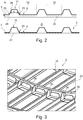
Fig. 2 shows a detail view of the structural component in two different views. -
Fig. 3 shows a partial view onto a structural component as a fuselage skin attached to a frame. -
Figs. 4a to 4d show a rear pressure bulkhead in a front view (4a), a rear view (4b), a front detail (4c) and a rear detail (4d). -
Fig. 5 shows a schematic view of a bonding area. -
Fig. 6 shows an aircraft having at least one such structural component. -
Fig.1 shows an exemplary embodiment of a stiffenedstructural component 2 as well as a very schematic illustration of a process for manufacturing thecomponent 2. Afirst material sheet 4 is provided, which comprises afirst surface 6 and asecond surface 8 on the opposite side. On thefirst surface 6, a plurality ofelongate bulges 10 are provided. They are arranged parallel and at a distance to each other. - The
bulges 10 bulge out from thefirst surface 6 into a direction transverse thereto. In doing so, they increase the moment of inertia around anaxis 12, which is schematically shown just for illustration purposes. - A
first section 14 of thefirst material sheet 4 comprises a plurality ofcutouts 16, which are arranged between neighboring bulges 10. Thecutouts 16 are arranged in a pattern or grid on thefirst material sheet 4 in order to createseveral webs first material sheet 4 to be flushly laid onto another surface. In asecond section 22, the spaces between neighboringbulges 10 are continuous and do not comprisecutouts 16. - The
first material sheet 4 is created through a pressing process. Thus, a planar base sheet as a starting point is formed through a pressing tool to not only provide a slight curvature as visible inFig. 1 , but also a plurality ofbulges 10. While thecutouts 16 may be formed by pressing, too, they may also be machined after or before the press-forming. - Different pressing methods are applicable depending on the material properties of the selected material for the
first material sheet 4. For example, a cold pressing may be conducted, such as a roll forming or a similar method. Hereby, the base sheet is fed into a roll forming tool and by passing through it, thebulges 10 and the curvature are created. Also, incremental and magnetic pulse forming processes may be used. - In a hot forming process, the base sheet is heated to a certain temperature, that depends on the selected material. If the material of the
first material sheet 4 is a metallic material, heating above a recrystallization temperature is feasible. In the case of aluminum alloy this may be a temperature of about or slightly above 300°C. After forming thebulges 10 into thefirst material sheet 4 as well as creating the curvature, the material may recrystallize, which leads to an improved mechanical stability. If, however, the material is a thermoplastic material, it may be heated to a certain temperature at which the material is clearly softened, but not molten. - An advantage of a hot forming process is an improved deformability of the material allowing to provide a plurality of different local and global deformations at once, i.e. in a single step. By adjusting the temperature of the material before deforming it, superior mechanical properties are achieved.
- In the example shown in
Fig. 1 , additionally asecond material sheet 24 is provided. In this example, thesecond material sheet 24 has a similar curvature as thefirst material sheet 4 but is realized as a continuous material sheet. Hence, thefirst material sheet 4 and thesecond material sheet 24 may be combined to form the stiffenedstructural component 2. Between bothmaterial sheets cutouts 16 the weight of thestructural component 2 is optimized. -
Fig. 2 shows a detailed lateral view of thefirst material sheet 4 from the direction indicated inFig. 1 by the letter A. Here, thebulges 10 are shown to comprise a symmetric trapezoid shape with a clear span s, which is decreasing with increasing distance from thefirst surface 6. Each of thebulges 10 has a foot region in the form of twoopposed edges 26 that are placed just on thefirst surface 6 and on a bulgingsurface 28 of therespective bulge 10. Theedges 26 are arranged at a distance to each other and extend along thefirst surface 6. Furthermore, between neighboring bulges 10 a substantiallyflat surface region 30 is present. - As shown in an upper part of
Fig. 2 , thefirst material sheet 4 is arranged on thesecond material sheet 24, wherein bothsheets bonding agent 32, such as a glue. Thus, bothmaterial sheets Fig. 2 . Here, thebulges 10 provide a stiffening function on one side of thecomponent 2, while thesecond material sheet 24 provides a continuously closed and smooth surface that is suitable for aircraft components directly exposed to an airflow. -
Fig. 3 shows thestructural components 2 as a part of a fuselage structure of an aircraft. Here, a part of acircular frame 34 is shown, to which thestructure component 2 is attached by usingseveral clips 36. Thecutouts 16 lead to a reduced effective thickness of a fuselage skin. Thebulges 10 comprise a common pitch, i.e. a distance between their longitudinal axes, as common stringers. However, due to their structure, they are able to provide an improved moment of inertia. -
Figure 4a, 4b ,4c and 4d show a further stiffenedstructural component 38 in the form of a rear pressure bulkhead.Fig. 4a shows a front view, i.e. the side of the pressure bulkhead that faces to the front of the aircraft and into the pressurized cabin. Here,several bulges 40 are radially arranged and distributed around acentral region 42. In this example, they are evenly distributed and thus enclose the same angles to each other throughout thepressure bulkhead 38. However, due to certain requiredinstallations -
Fig. 4c shows thebulges 40 and in a three-dimensional view. Thepressure bulkhead 38 with its curvature as well as its plurality ofbulges 40 may be created in a single manufacturing, i.e. pressing step.Fig. 4b shows a rear view of thepressure bulkhead 38 comprisingopen sides 48 of thebulges 40. They may be closed bycover plates 50 as shown infigure 4d . -
Fig. 5 shows a schematic view of a bonding area between thefirst material sheet 4 and thesecond material sheet 24 of the first exemplary embodiment. Here, different aspects are shown for optimizing the mechanical properties of thecomponent 2. A bondedarea 52 includes thebonding agent 32 between bothmaterial sheets area 52 surrounds thecutouts 16.Several bulges 10 are arranged parallel and at a distance to each other and extend along the bondedarea 52. Exemplarily, they may enclose asurface area 54 that does not comprisecutouts 16 and that is machined for a variable thickness for optimization purposes. The same applies to asurface area 56 betweencutouts 16. Thebulges 10 may be filled with alightweight material 58 that may be a foam or another material with a low density or may be left completely hollow. - Finally,
Fig. 6 shows anaircraft 60 having afuselage 62,wings 64, atail plane 66 with ahorizontal tail plane 68 and avertical tail plane 70. On a rear side underneath all forward of thetail plane 66, arear pressure bulkhead 38 may be placed. Thefuselage 62 may comprise at least onecomponent 2 explained above. Also, thewings 64 may comprise at least one such stiffenedstructural component 2. - In addition, it should be pointed out that "comprising" does not exclude other elements or steps, and "a" or "an" does not exclude a plural number. Furthermore, it should be pointed out that characteristics or steps which have been described with reference to one of the above exemplary embodiments may also be used in combination with other characteristics or steps of other exemplary embodiments described above. Reference characters in the claims are not to be interpreted as limitations.
-
- 2
- Stiffened structural component
- 4
- first material sheet
- 6
- first surface
- 8
- second surface
- 10
- bulge
- 12
- axis
- 14
- first section
- 16
- cutout
- 18
- web
- 20
- web
- 22
- second section
- 24
- second material sheet
- 26
- edge
- 28
- bulging surface
- 30
- flat surface region
- 32
- bonding agent
- 34
- circular frame
- 36
- clip
- 38
- stiffened structural component
- 40
- bulge
- 42
- central region
- 44
- installation
- 46
- installation
- 48
- open side
- 50
- cover plate
- 52
- bonded area
- 54
- surface area
- 56
- surface area
- 58
- lightweight material
- 60
- aircraft
- 62
- fuselage
- 64
- wing
- 66
- tail plane
- 68
- horizontal tail plane
- 70
- vertical tail plane
Claims (15)
- A stiffened structural component (2, 38) for an aircraft (60), comprising- a first material sheet (4) with a first surface (6), and- at least one elongate bulge (10, 40) that bulges out in a direction transverse to the first surface (6) in order to stiffen the structural component (2, 38),wherein each of the at least one bulge (10, 40) comprises two edges (26) that extend along the first surface (6),
wherein a continuous bulging surface (28) extends between the edges (26), and
wherein into the first material sheet (4) the bulges (10, 40) are formed integrally through pressing. - The structural component (2, 38) of claim 1, wherein the component (2, 38) comprises a plurality of bulges (10, 40) that are arranged at a distance to each other.
- The structural component (2, 38) of claim 1 or 2, wherein the bulging surface (28) comprises a symmetric hollow profile.
- The structural component (2, 38) of any of the preceding claims, wherein the bulges (10, 40) are arranged on the first surface (6) in a regular pattern.
- The structural component (2, 38) of any of the preceding claims, wherein the bulges (10, 40) comprise a height in a range of 3 to 50 mm.
- The structural component (2, 38) of any of the preceding claims,
wherein the material of the first material sheet (4) is not precipitation hardenable. - The structural component (2, 38) of any of the preceding claims,
wherein the bulges (10, 40) are formed by a hot forming process. - The structural component (2, 38) of any of the preceding claims,
further comprising second material sheet (24), which is attached to the second surface (8) of the first material sheet (4). - The structural component (2, 38) of claim 8,
wherein the second material sheet (24) is attached to the first material sheet (4) through material bonding. - The structural component (2, 38) of any of the preceding claims,
wherein the first material sheet (4) comprises at least one cutout (16) between at least two bulges (10, 40). - The structural component (2, 38) of any of the preceding claims,
further comprising at least one cover plate (50) for covering a bulge (10, 40) on a side opposite the bulging surface (28). - The structural component (2, 38) of any of the preceding claims,
wherein the component (2, 38) is a rear pressure bulkhead for a pressurized cabin of an aircraft (60), the rear pressure bulkhead comprising a plurality of radial bulges (10, 40) distributed around a central region (42) of the rear pressure bulkhead. - The structural component (2, 38) of any of the claims 1 to 11,
wherein the component (2, 38) is a fuselage skin component for a fuselage (62) of an aircraft (60), the fuselage skin component comprising a plurality of axial bulges (10, 40) arranged parallel and at a distance to each other. - Aircraft (60), having at least one structural component (2, 38) of any of the preceding claims.
- Aircraft (60) according to claim 14, wherein the at least one structural component (2, 38) is selected from a group of structural components, the group consisting of- a fuselage skin component,- an airframe component,- a rear pressure bulkhead,- a wing shell,- a horizontal tail plane shell,- a vertical tail plane shell,- floor panels for a cabin of the aircraft,- primary or secondary flight control surfaces,- movable flow bodies in general.
Priority Applications (3)
| Application Number | Priority Date | Filing Date | Title |
|---|---|---|---|
| EP19165843.4A EP3715241A1 (en) | 2019-03-28 | 2019-03-28 | A stiffened structural component for an aircraft |
| US16/815,225 US11541982B2 (en) | 2019-03-28 | 2020-03-11 | Stiffened structural component for an aircraft |
| CN202010224706.1A CN111746778A (en) | 2019-03-28 | 2020-03-26 | Reinforced structural component for an aircraft |
Applications Claiming Priority (1)
| Application Number | Priority Date | Filing Date | Title |
|---|---|---|---|
| EP19165843.4A EP3715241A1 (en) | 2019-03-28 | 2019-03-28 | A stiffened structural component for an aircraft |
Publications (1)
| Publication Number | Publication Date |
|---|---|
| EP3715241A1 true EP3715241A1 (en) | 2020-09-30 |
Family
ID=66001021
Family Applications (1)
| Application Number | Title | Priority Date | Filing Date |
|---|---|---|---|
| EP19165843.4A Withdrawn EP3715241A1 (en) | 2019-03-28 | 2019-03-28 | A stiffened structural component for an aircraft |
Country Status (3)
| Country | Link |
|---|---|
| US (1) | US11541982B2 (en) |
| EP (1) | EP3715241A1 (en) |
| CN (1) | CN111746778A (en) |
Cited By (1)
| Publication number | Priority date | Publication date | Assignee | Title |
|---|---|---|---|---|
| CN112373714A (en) * | 2020-10-14 | 2021-02-19 | 浙江大学 | Wing surface operation platform of wing box of large airplane wing |
Families Citing this family (6)
| Publication number | Priority date | Publication date | Assignee | Title |
|---|---|---|---|---|
| CN113443118B (en) * | 2021-09-01 | 2022-01-25 | 成都飞机工业(集团)有限责任公司 | Aircraft component, filling structure for aircraft component process stiffening and installation method |
| US11993388B2 (en) | 2021-09-02 | 2024-05-28 | Rohr, Inc. | Corrugated stiffening devices utilizing peaks and valleys and methods of manufacture |
| US12014712B2 (en) | 2021-09-02 | 2024-06-18 | Rohr, Inc. | Corrugated acoustic stiffening devices and methods |
| US11780179B2 (en) | 2021-09-02 | 2023-10-10 | Rohr, Inc. | Thermoplastic composite panel with corrugated peaks and troughs stiffening systems and methods |
| EP4613636A1 (en) * | 2024-03-04 | 2025-09-10 | Airbus Operations GmbH | Flat bulkheads, an aircraft, and a method of producing a flat bulkhead |
| US20250320884A1 (en) * | 2024-04-10 | 2025-10-16 | Textron Aviation, Inc. | Method for forming a reinforced aluminum component and reinforced aluminum component |
Citations (5)
| Publication number | Priority date | Publication date | Assignee | Title |
|---|---|---|---|---|
| US20040075023A1 (en) | 2002-08-22 | 2004-04-22 | Herwig Assler | Lightweight structural component made of metallic ply materials |
| DE102009060706A1 (en) * | 2009-12-29 | 2011-06-30 | Airbus Operations GmbH, 21129 | Method and device for producing a stiffening structure for an aircraft fuselage segment and a stiffening structure |
| WO2012150240A1 (en) * | 2011-05-02 | 2012-11-08 | Daher Aerospace | Self-stiffened composite panel, particularly for an aircraft floor, and method for manufacturing such a panel |
| US20140145031A1 (en) * | 2012-11-26 | 2014-05-29 | The Boeing Company | Vertically Integrated Stringers |
| EP2824031A2 (en) * | 2013-07-08 | 2015-01-14 | The Boeing Company | Pressure panels |
Family Cites Families (2)
| Publication number | Priority date | Publication date | Assignee | Title |
|---|---|---|---|---|
| US5893534A (en) * | 1995-12-22 | 1999-04-13 | The Boeing Company | Structural apparatus and design to prevent oil can movement of webs in aircraft pressure bulkheads |
| NL2005536C2 (en) * | 2010-10-15 | 2012-04-17 | Univ Delft Tech | Aircraft wing and fiber metal laminate forming part of such an aircraft wing. |
-
2019
- 2019-03-28 EP EP19165843.4A patent/EP3715241A1/en not_active Withdrawn
-
2020
- 2020-03-11 US US16/815,225 patent/US11541982B2/en active Active
- 2020-03-26 CN CN202010224706.1A patent/CN111746778A/en active Pending
Patent Citations (5)
| Publication number | Priority date | Publication date | Assignee | Title |
|---|---|---|---|---|
| US20040075023A1 (en) | 2002-08-22 | 2004-04-22 | Herwig Assler | Lightweight structural component made of metallic ply materials |
| DE102009060706A1 (en) * | 2009-12-29 | 2011-06-30 | Airbus Operations GmbH, 21129 | Method and device for producing a stiffening structure for an aircraft fuselage segment and a stiffening structure |
| WO2012150240A1 (en) * | 2011-05-02 | 2012-11-08 | Daher Aerospace | Self-stiffened composite panel, particularly for an aircraft floor, and method for manufacturing such a panel |
| US20140145031A1 (en) * | 2012-11-26 | 2014-05-29 | The Boeing Company | Vertically Integrated Stringers |
| EP2824031A2 (en) * | 2013-07-08 | 2015-01-14 | The Boeing Company | Pressure panels |
Cited By (1)
| Publication number | Priority date | Publication date | Assignee | Title |
|---|---|---|---|---|
| CN112373714A (en) * | 2020-10-14 | 2021-02-19 | 浙江大学 | Wing surface operation platform of wing box of large airplane wing |
Also Published As
| Publication number | Publication date |
|---|---|
| US20200307756A1 (en) | 2020-10-01 |
| US11541982B2 (en) | 2023-01-03 |
| CN111746778A (en) | 2020-10-09 |
Similar Documents
| Publication | Publication Date | Title |
|---|---|---|
| US11541982B2 (en) | Stiffened structural component for an aircraft | |
| US8292227B2 (en) | Aircraft wings having continuously tailored structural strength | |
| US4284443A (en) | Single stage hot bonding method for producing composite honeycomb core structures | |
| US4304376A (en) | Composite honeycomb core structures and single stage hot bonding method of producing such structures | |
| EP2376328B1 (en) | Aerofoil structure with corrugated reinforcing member | |
| CN105438438B (en) | Composite wing edge attachment and method | |
| EP2886452B1 (en) | Flow body, method for manufacturing a flow body and aircraft having such a flow body | |
| US8104714B2 (en) | Apparatuses and methods for joining composite members and other structural members in aircraft wing boxes and other structures | |
| JP6247048B2 (en) | Aircraft bonded composite wing | |
| US8353479B2 (en) | Arrangement of two fuselage sections of an aircraft and a connecting structure for connecting fuselage skins | |
| CN107082111B (en) | Plate and method for improving laminar flow | |
| RU2693141C2 (en) | Panel design and corresponding method | |
| EP2589532A2 (en) | Aircraft fuselage made out with composite material and manufacturing processes | |
| WO2008012569A2 (en) | Aircrat wing box and manufacture thereof | |
| CN106573674A (en) | Aircraft frame structure, method for producing an aircraft frame structure, method for repairing an aircraft, and aircraft component | |
| US5362347A (en) | Fusion bonded thermoplastic leading edge for aircraft aerodynamic surfaces | |
| EP2556947A2 (en) | Vertical laminate noodly for high capacity pull-off for a composite stringer | |
| GB2475376A (en) | Title: Aircraft morphing panel with webbed core and composite facesheets | |
| US11273899B2 (en) | Wing rib, wing having wing rib, and method for manufacturing the same | |
| US20040075023A1 (en) | Lightweight structural component made of metallic ply materials | |
| US20140315040A1 (en) | Integrally formed stiffener | |
| EP2948367B1 (en) | An aerial skin article with reinforced fastening holes | |
| EP3492369B1 (en) | Leading-edge arrangement for a flow body of an aircraft | |
| EP3652067B1 (en) | Fitting for a stiffened panel | |
| EP3275778B1 (en) | Curved aircraft substructure repairs systems and methods |
Legal Events
| Date | Code | Title | Description |
|---|---|---|---|
| PUAI | Public reference made under article 153(3) epc to a published international application that has entered the european phase |
Free format text: ORIGINAL CODE: 0009012 |
|
| STAA | Information on the status of an ep patent application or granted ep patent |
Free format text: STATUS: THE APPLICATION HAS BEEN PUBLISHED |
|
| AK | Designated contracting states |
Kind code of ref document: A1 Designated state(s): AL AT BE BG CH CY CZ DE DK EE ES FI FR GB GR HR HU IE IS IT LI LT LU LV MC MK MT NL NO PL PT RO RS SE SI SK SM TR |
|
| AX | Request for extension of the european patent |
Extension state: BA ME |
|
| STAA | Information on the status of an ep patent application or granted ep patent |
Free format text: STATUS: THE APPLICATION IS DEEMED TO BE WITHDRAWN |
|
| 18D | Application deemed to be withdrawn |
Effective date: 20210331 |