EP3715193B1 - Cleaning nozzle unit and on-vehicle camera unit - Google Patents
Cleaning nozzle unit and on-vehicle camera unit Download PDFInfo
- Publication number
- EP3715193B1 EP3715193B1 EP20164155.2A EP20164155A EP3715193B1 EP 3715193 B1 EP3715193 B1 EP 3715193B1 EP 20164155 A EP20164155 A EP 20164155A EP 3715193 B1 EP3715193 B1 EP 3715193B1
- Authority
- EP
- European Patent Office
- Prior art keywords
- lens
- cleaning solution
- cleaning
- liquid passage
- air
- Prior art date
- Legal status (The legal status is an assumption and is not a legal conclusion. Google has not performed a legal analysis and makes no representation as to the accuracy of the status listed.)
- Active
Links
Images




Classifications
-
- B—PERFORMING OPERATIONS; TRANSPORTING
- B05—SPRAYING OR ATOMISING IN GENERAL; APPLYING FLUENT MATERIALS TO SURFACES, IN GENERAL
- B05B—SPRAYING APPARATUS; ATOMISING APPARATUS; NOZZLES
- B05B1/00—Nozzles, spray heads or other outlets, with or without auxiliary devices such as valves, heating means
- B05B1/30—Nozzles, spray heads or other outlets, with or without auxiliary devices such as valves, heating means designed to control volume of flow, e.g. with adjustable passages
- B05B1/32—Nozzles, spray heads or other outlets, with or without auxiliary devices such as valves, heating means designed to control volume of flow, e.g. with adjustable passages in which a valve member forms part of the outlet opening
- B05B1/323—Nozzles, spray heads or other outlets, with or without auxiliary devices such as valves, heating means designed to control volume of flow, e.g. with adjustable passages in which a valve member forms part of the outlet opening the valve member being actuated by the pressure of the fluid to be sprayed
-
- B—PERFORMING OPERATIONS; TRANSPORTING
- B60—VEHICLES IN GENERAL
- B60S—SERVICING, CLEANING, REPAIRING, SUPPORTING, LIFTING, OR MANOEUVRING OF VEHICLES, NOT OTHERWISE PROVIDED FOR
- B60S1/00—Cleaning of vehicles
- B60S1/02—Cleaning windscreens, windows or optical devices
- B60S1/56—Cleaning windscreens, windows or optical devices specially adapted for cleaning other parts or devices than front windows or windscreens
- B60S1/60—Cleaning windscreens, windows or optical devices specially adapted for cleaning other parts or devices than front windows or windscreens for signalling devices, e.g. reflectors
-
- B—PERFORMING OPERATIONS; TRANSPORTING
- B60—VEHICLES IN GENERAL
- B60S—SERVICING, CLEANING, REPAIRING, SUPPORTING, LIFTING, OR MANOEUVRING OF VEHICLES, NOT OTHERWISE PROVIDED FOR
- B60S1/00—Cleaning of vehicles
- B60S1/02—Cleaning windscreens, windows or optical devices
- B60S1/56—Cleaning windscreens, windows or optical devices specially adapted for cleaning other parts or devices than front windows or windscreens
-
- B—PERFORMING OPERATIONS; TRANSPORTING
- B05—SPRAYING OR ATOMISING IN GENERAL; APPLYING FLUENT MATERIALS TO SURFACES, IN GENERAL
- B05B—SPRAYING APPARATUS; ATOMISING APPARATUS; NOZZLES
- B05B1/00—Nozzles, spray heads or other outlets, with or without auxiliary devices such as valves, heating means
- B05B1/26—Nozzles, spray heads or other outlets, with or without auxiliary devices such as valves, heating means with means for mechanically breaking-up or deflecting the jet after discharge, e.g. with fixed deflectors; Breaking-up the discharged liquid or other fluent material by impinging jets
- B05B1/262—Nozzles, spray heads or other outlets, with or without auxiliary devices such as valves, heating means with means for mechanically breaking-up or deflecting the jet after discharge, e.g. with fixed deflectors; Breaking-up the discharged liquid or other fluent material by impinging jets with fixed deflectors
- B05B1/267—Nozzles, spray heads or other outlets, with or without auxiliary devices such as valves, heating means with means for mechanically breaking-up or deflecting the jet after discharge, e.g. with fixed deflectors; Breaking-up the discharged liquid or other fluent material by impinging jets with fixed deflectors the liquid or other fluent material being deflected in determined directions
-
- B—PERFORMING OPERATIONS; TRANSPORTING
- B05—SPRAYING OR ATOMISING IN GENERAL; APPLYING FLUENT MATERIALS TO SURFACES, IN GENERAL
- B05B—SPRAYING APPARATUS; ATOMISING APPARATUS; NOZZLES
- B05B7/00—Spraying apparatus for discharge of liquids or other fluent materials from two or more sources, e.g. of liquid and air, of powder and gas
- B05B7/02—Spray pistols; Apparatus for discharge
- B05B7/04—Spray pistols; Apparatus for discharge with arrangements for mixing liquids or other fluent materials before discharge
- B05B7/0416—Spray pistols; Apparatus for discharge with arrangements for mixing liquids or other fluent materials before discharge with arrangements for mixing one gas and one liquid
- B05B7/0483—Spray pistols; Apparatus for discharge with arrangements for mixing liquids or other fluent materials before discharge with arrangements for mixing one gas and one liquid with gas and liquid jets intersecting in the mixing chamber
-
- B—PERFORMING OPERATIONS; TRANSPORTING
- B05—SPRAYING OR ATOMISING IN GENERAL; APPLYING FLUENT MATERIALS TO SURFACES, IN GENERAL
- B05B—SPRAYING APPARATUS; ATOMISING APPARATUS; NOZZLES
- B05B7/00—Spraying apparatus for discharge of liquids or other fluent materials from two or more sources, e.g. of liquid and air, of powder and gas
- B05B7/02—Spray pistols; Apparatus for discharge
- B05B7/08—Spray pistols; Apparatus for discharge with separate outlet orifices, e.g. to form parallel jets, i.e. the axis of the jets being parallel, to form intersecting jets, i.e. the axis of the jets converging but not necessarily intersecting at a point
- B05B7/0807—Spray pistols; Apparatus for discharge with separate outlet orifices, e.g. to form parallel jets, i.e. the axis of the jets being parallel, to form intersecting jets, i.e. the axis of the jets converging but not necessarily intersecting at a point to form intersecting jets
- B05B7/0846—Spray pistols; Apparatus for discharge with separate outlet orifices, e.g. to form parallel jets, i.e. the axis of the jets being parallel, to form intersecting jets, i.e. the axis of the jets converging but not necessarily intersecting at a point to form intersecting jets with jets being only jets constituted by a liquid or a mixture containing a liquid
-
- B—PERFORMING OPERATIONS; TRANSPORTING
- B60—VEHICLES IN GENERAL
- B60S—SERVICING, CLEANING, REPAIRING, SUPPORTING, LIFTING, OR MANOEUVRING OF VEHICLES, NOT OTHERWISE PROVIDED FOR
- B60S1/00—Cleaning of vehicles
- B60S1/02—Cleaning windscreens, windows or optical devices
- B60S1/46—Cleaning windscreens, windows or optical devices using liquid; Windscreen washers
- B60S1/48—Liquid supply therefor
- B60S1/52—Arrangement of nozzles; Liquid spreading means
-
- B—PERFORMING OPERATIONS; TRANSPORTING
- B60—VEHICLES IN GENERAL
- B60S—SERVICING, CLEANING, REPAIRING, SUPPORTING, LIFTING, OR MANOEUVRING OF VEHICLES, NOT OTHERWISE PROVIDED FOR
- B60S1/00—Cleaning of vehicles
- B60S1/02—Cleaning windscreens, windows or optical devices
- B60S1/54—Cleaning windscreens, windows or optical devices using gas, e.g. hot air
-
- G—PHYSICS
- G02—OPTICS
- G02B—OPTICAL ELEMENTS, SYSTEMS OR APPARATUS
- G02B27/00—Optical systems or apparatus not provided for by any of the groups G02B1/00 - G02B26/00, G02B30/00
- G02B27/0006—Optical systems or apparatus not provided for by any of the groups G02B1/00 - G02B26/00, G02B30/00 with means to keep optical surfaces clean, e.g. by preventing or removing dirt, stains, contamination, condensation
Definitions
- the present invention relates to a cleaning nozzle unit, and an on-vehicle camera unit.
- WO2014/010580 discloses a system that washes dirt adhering to a lens to such an extent as not to impair a sensing function by the on-vehicle camera, by providing nozzles on an upper side of the lens of the on-vehicle camera that senses a vehicle rear direction, and injecting compressed air and a cleaning solution from the nozzles.
- Japanese Patent Laid-Open No. 2012-132988 discloses an art of using air that is controlled to be conditioned by an air-conditioning device for air used in cleaning the lens of an on-vehicle camera in a configuration where nozzles are provided on an upper side of the lens of the on-vehicle camera.
- US 2015/151722 A1 shows a cleaning nozzle unit according to the preamble of claim 1.
- US 2014/0060582 A1 shows cleaning nozzle unit wherein a plurality of the injection ports are provided and inject the mixtures in directions such that the mixtures hits each other in the surface at a substantially predetermined angle in a front view of a surface of an object.
- a configuration can be also considered, in which a nozzle for cleaning dirt on the lower side of the lens is separately added to the lower side of the lens, but in doing so, there arise new problems such as increase in the number of components for cleaning, complication of the structure, and increase in size.
- air used in cleaning the lens of the on-vehicle camera is air that is controlled to be conditioned by the air-conditioning device, and therefore, there is also the problem that pressure of air injected from the nozzles is relatively low. Therefore, in cleaning the on-vehicle camera mounted in front of the vehicle, pressure of air that is injected is defeated by pressure of traveling wind, and the lens may not be cleaned normally. Further, since the injected pressure is low, an ability to eliminate clogging occurring to the nozzles also becomes low, and even mild clogging cannot sometimes be cleaned.
- An aspect of the present invention has an object to provide a cleaning nozzle unit and an on-vehicle camera unit which are capable of enhancing cleaning performance.
- the invention provides a cleaning nozzle unit according to claim 1.
- the cleaning nozzle unit includes an inner liquid passage guiding a cleaning solution, an inner air passage feeding air to an outlet of the inner liquid passage and an injection port that mixes the cleaning solution guided by the inner liquid passage and the air fed by the inner air passage and injects a mixture of the cleaning solution and the air to a surface of an object, wherein a plurality of the injection ports are provided, are disposed at predetermined intervals and inject the mixtures in directions such that the mixtures hits each other in the surface at a substantially predetermined angle in a front view of the surface.
- An aspect of the present invention is the above described cleaning nozzle unit, wherein in a case that injection ports are installed in an on-vehicle camera, the object is a lens of the on-vehicle camera, the injection ports are disposed at angles so that the mixtures hits each other at an apex of the lens in a spherical shape.
- An aspect of the present invention is the above described cleaning nozzle unit, wherein a number of the injection ports is two, and an angle formed by the two injection ports is 50 degrees or more, and less than 180 degrees seen from the apex of the lens.
- the on-vehicle camera unit 1 of the present embodiment continuously injects the cleaning solution mists 47 in a fan shape in front view at a substantially same flow velocities from the respective injection ports 48 toward the apex O of the lens 8 as illustrated in Fig. 6 at a time of cleaning operation.
- the cleaning solution mist 47 is injected in the fan shape in front view, whereby the cleaning solution mist 47 advances to the apex O while washing the wide range of the surface 8A at the upper side from the apex O of the lens 8.
- the cleaning solution mists 47 of a continuous flow rate collide with each other in the apex O, and thereby the turbulent flow in which the cleaning solution mist 47 flows to a lower pressure side continuously occurs in the range D in which collision of the cleaning solution mists 47 occurs in side view as schematically illustrated in Fig. 8 .
- the directions where the pressure is low in the range D are two directions that are a direction to separate from the lens 8, and a direction to approach the lens 8, and therefore, the turbulent flow including a first air current E1 in the direction to separate from the lens 8, and a second air current E2 toward the lens 8 continuously occurs in the range D.
- the second air current E2 generates the cleaning solution mist 47 at a high flow velocity toward the range C close to the other side edge portion, and dirt in the range C close to the other side edge portion is scraped out and cleaned by the cleaning solution mist 47. Thereby, a cleaning force of the range C close to the other side edge portion is enhanced.
- a distance between the injection port 48 and the lens 8, and the flow velocity of the cleaning solution mist 47 at the time of injection are set at values with which the cleaning solution mist 47 reliably reaches the apex O against wind pressure of the traveling wind and wind outside the vehicle.
- the disposition angles ⁇ of the two injection ports 48 are desirably certain angles or more, and it is confirmed that the range C close to the other side edge portion can be cleaned when the disposition angle ⁇ is at least 25 degrees or more (an angle formed by the two injection ports 48 is 50 degrees or more).
- an upper limit of the disposition angle ⁇ of each of the injection ports 48 is a maximum angle that generates a downward component in front view, that is, an angle of less than 90 degrees (an angle formed by the two injection ports 48 is less than 180 degrees), in the composite vector of the cleaning solution mists 47 that collide at the apex O.
- the number of injection ports 48 is not limited to two.
- each of the injection ports 48 is disposed in a position laterally symmetrical about the vertical line A2 in a range of an upper side of the horizontal line A1, in front view.
- the cleaning solution mists 47 are injected from the respective injection ports 48 at a flow velocity with which downward components in front view are generated in the composite vector of the cleaning solution mists 47 that collide with each other at the apex O.
- the flow velocities of the respective cleaning solution mists 47 may be same, or may be different according to the injection ports 48.
- the cleaning nozzle unit 4 of the present embodiment is configured such that each of the injection ports 48 is disposed on the upper side from the apex O of the lens 8 in front view of the lens 8, and the cleaning solution mists 47 injected from the respective injection ports 48 collide with each other on the surface 8A of the lens 8.
- a turbulent flow including the first air current E1 in the direction to separate from the lens 8, and the second air current E2 toward the lens 8 is generated in the range D where the cleaning solution mists 47 collide with each other. Therefore, the surface 8A of the lens 8 is cleaned by using the cleaning solution mists 47 generated by the second air current E2, and cleaning ability can be enhanced.
- the number of injection ports 48 is two, the angle formed by the two injection ports 48 seen from the apex O is 50 degrees or more, and is less than 180 degrees, and therefore the second air current E2 with the appropriate strength for cleaning of the range of the lower side from the apex O can be easily generated as compared with a configuration in which three or more injection ports 48 are provided.
- the cleaning nozzle unit 4 of the present embodiment includes the inner liquid passage outlet 72 of the inner liquid passage 60, the tip end liquid passage 64 connecting the inner liquid passage outlet 72 and the injection port 48, and the lid body 80 that closes the inner liquid passage outlet 72, and opens the inner liquid passage outlet 72 by elastically deforming by hydraulic pressure of the cleaning solution when the cleaning solution is fed to the inner liquid passage 60.
- the lens in the spherical shape is illustrated as the lens 8, but the surface 8A does not always have to be a complete spherical surface.
- the on-vehicle camera unit 1 may be disposed at a left side or a right side of the vehicle body.
- traveling wind mainly advances from the front of the vehicle to the rear. Therefore, the on-vehicle camera unit 1 is preferably provided in an orientation in which the injection ports 48 are located at a windward side of the traveling wind, and the range C close to the other side edge portion is located at a lee side.
- the injection direction of the cleaning solution mist 47 is matched with the direction of the traveling wind, and therefore the cleaning solution mist 47 does not collide at a side closer to the injection port 48 (side away from the range C close to the other side edge portion) than the apex O by being defeated by the wind pressure of the traveling wind.
- directions such as horizontal, and vertical, various numeric values, and shapes do not consciously exclude these directions, a range of the periphery of the numeric values, and approximate shapes unless otherwise noted, and includes the peripheral range and the approximate shapes (a so-called equivalent range) as long as the same operation effect is provided, and as long as the values do not deviate from the critical significance.
- a cleaning nozzle unit (4) including an inner liquid passage (60) guiding a cleaning solution, an inner air passage (61) feeding air to an outlet (72) of the inner liquid passage (60), and an injection port (48) that mixes the cleaning solution guided by the inner liquid passage (60) and the air fed by the inner air passage (61) and injects a mixture (47) of the cleaning solution and the air to a surface (8A) of an object (8)
- a plurality of the injection ports (48) are provided, are disposed at predetermined intervals and inject the mixtures (47) in directions such that the mixtures (47) hits each other in the surface (8A) at a substantially predetermined angle in a front view of the surface (8A).
Landscapes
- Engineering & Computer Science (AREA)
- Mechanical Engineering (AREA)
- Water Supply & Treatment (AREA)
- Physics & Mathematics (AREA)
- General Physics & Mathematics (AREA)
- Optics & Photonics (AREA)
- Studio Devices (AREA)
- Nozzles (AREA)
- Closed-Circuit Television Systems (AREA)
- Structure And Mechanism Of Cameras (AREA)
- Accessories Of Cameras (AREA)
Description
- The present invention relates to a cleaning nozzle unit, and an on-vehicle camera unit.
- As an art of cleaning a lens of an on-vehicle camera unit, there have been known International Publication No.
WO 2014/010580 andJapanese Patent Laid-Open No. 2012-132988 - International Publication No.
WO2014/010580 discloses a system that washes dirt adhering to a lens to such an extent as not to impair a sensing function by the on-vehicle camera, by providing nozzles on an upper side of the lens of the on-vehicle camera that senses a vehicle rear direction, and injecting compressed air and a cleaning solution from the nozzles. -
Japanese Patent Laid-Open No. 2012-132988 -
US 2015/151722 A1 shows a cleaning nozzle unit according to the preamble ofclaim 1. -
US 2014/0060582 A1 shows cleaning nozzle unit wherein a plurality of the injection ports are provided and inject the mixtures in directions such that the mixtures hits each other in the surface at a substantially predetermined angle in a front view of a surface of an object. - In cleaning from the nozzles provided on the upper side of the lens as in the arts of International Publication No.
WO 2014/010580 , andJapanese Patent Laid-Open No. 2014-132988 - In order to solve the problem, it is conceivable to provide a nozzle in a position where the nozzle protrudes so as not to produce a shadow on the surface of the spherical lens. However, in doing so, there arise new problems that the nozzle enters an angle of view that is used for sensing, and the nozzle is excessively protruded from a vehicle body.
- Further, a configuration can be also considered, in which a nozzle for cleaning dirt on the lower side of the lens is separately added to the lower side of the lens, but in doing so, there arise new problems such as increase in the number of components for cleaning, complication of the structure, and increase in size.
- Further, in the art of
Japanese Patent Laid-Open No. 2012-132988 - An aspect of the present invention has an object to provide a cleaning nozzle unit and an on-vehicle camera unit which are capable of enhancing cleaning performance.
- The invention provides a cleaning nozzle unit according to
claim 1. - According to the present invention the cleaning nozzle unit includes an inner liquid passage guiding a cleaning solution, an inner air passage feeding air to an outlet of the inner liquid passage and an injection port that mixes the cleaning solution guided by the inner liquid passage and the air fed by the inner air passage and injects a mixture of the cleaning solution and the air to a surface of an object, wherein a plurality of the injection ports are provided, are disposed at predetermined intervals and inject the mixtures in directions such that the mixtures hits each other in the surface at a substantially predetermined angle in a front view of the surface.
- An aspect of the present invention is the above described cleaning nozzle unit, wherein in a case that injection ports are installed in an on-vehicle camera, the object is a lens of the on-vehicle camera, the injection ports are disposed at angles so that the mixtures hits each other at an apex of the lens in a spherical shape.
- An aspect of the present invention is the above described cleaning nozzle unit, wherein a number of the injection ports is two, and an angle formed by the two injection ports is 50 degrees or more, and less than 180 degrees seen from the apex of the lens.
- According to the present invention, the cleaning nozzle unit includes a lid body that closes the outlet of the inner liquid passage and opens the outlet of the inner liquid passage by elastically deforming by hydraulic pressure of the cleaning solution when the cleaning solution is fed to the inner liquid passage.
- An aspect of the present invention provides an on-vehicle camera unit, including an on-vehicle camera having a spherical lens, and the cleaning nozzle unit according to any one of the above described aspects.
- According to an aspect of the present invention, cleaning performance can be enhanced.
-
-
Fig. 1 is a perspective view illustrating a configuration of an on-vehicle camera unit; -
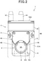
Fig. 2 is a front view of the on-vehicle camera unit; -
Fig. 3 is an exploded perspective view in which a tip end portion of a nozzle portion is exploded; -
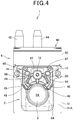
Fig. 4 is a front view of a state where a tip end cover is detached from the tip end portion of the nozzle portion; -
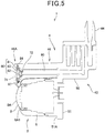
Fig. 5 is a vertical sectional view of the on-vehicle camera unit; -
Fig. 6 is a front view schematically illustrating an injection state of cleaning solution mist; -
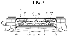
Fig. 7 is a view of an injection port of a cleaning nozzle unit seen from a lower side of a lens; and -
Fig. 8 is a view of a vicinity of the injection port of the cleaning nozzle unit seen from a side face of the lens. - Hereinafter, an embodiment of the present invention will be described with reference to the drawings.
-
Fig. 1 is a perspective view illustrating a configuration of an on-vehicle camera unit 1, andFig. 2 is a front view of the on-vehicle camera unit 1. - As illustrated in
Fig. 1 andFig. 2 , the on-vehicle camera unit 1 is a unit including an on-vehicle camera 2 that captures video of surroundings of a vehicle, and acleaning nozzle unit 4 for cleaning the on-vehicle camera 2, and the on-vehicle camera unit 1 is installed in front, in rear, at a left side, at a right side, and the like of a vehicle body of the vehicle in a states exposed outside of the vehicle. Hereinafter, a case is illustrated, in which the on-vehicle camera unit 1 is disposed in front or in rear of the vehicle body, and traveling wind at the time of vehicle traveling mainly hits the on-vehicle camera unit 1 from a front. - The on-
vehicle camera 2 includes acamera body case 6 and alens 8. Thecamera body case 6 forms a substantially rectangular parallelepiped shape, in which an imaging element that is an optical sensor and various electric circuits are housed. Thelens 8 is mounted to afront face 6A of thecamera body case 6, is an optical element forming an image on the capturing element, and a spherical lens that is one of convex lenses is used in the present embodiment. - In the
lens 8, asurface 8A of thelens 8 has a water repellency due to water repellent coating. Further, in thecamera body case 6, a lens contact portion 6A1 contacting at least thelens 8, of thefront face 6A, has hydrophilicity by being formed from a hydrophilic material (for example, a hydrophilic resin). When thelens 8 is wetted by rain or the like, water smoothly moves from thesurface 8A having water repellency to the lens contact portion 6A1 having hydrophilicity, and thus favorable drainage of thesurface 8A is realized. - Further, the vehicle is loaded with a
cleaning device 20 that cleans thelens 8 of the on-vehicle camera 2 by injecting a cleaning solution in a mist state (a mixture) (hereinafter, referred to as "cleaning solution mist 47" (seeFig. 6 )) at appropriate timings during stoppage and during travel, and thecleaning nozzle unit 4 is one component of thecleaning device 20. - As illustrated in
Fig. 1 , thecleaning device 20 includes a cleaningsolution storage tank 22 storing a cleaning solution, acleaning solution pump 26 feeding the cleaning solution of the cleaningsolution storage tank 22 to thecleaning nozzle unit 4 through acleaning solution tube 24, anair pump 30 feeding compressed air to thecleaning nozzle unit 4 through anair tube 28, and acontrol device 31 controlling thecleaning solution pump 26 and theair pump 30, in addition to thecleaning nozzle unit 4. - The
cleaning nozzle unit 4 is a unit configured to be connectable to thecleaning solution tube 24 and theair tube 28, and includes aunit body 40 and anozzle portion 46. - The
unit body 40 has abody portion 50, and amounting portion 51, and thebody portion 50 and themounting portion 51 are integrally molded. Thebody portion 50 forms a substantially rectangular parallelepiped shape, and on atop surface 50A thereof, acleaning solution connector 42 that is a connection terminal of thecleaning solution tube 24, and anair connector 44 that is a connection terminal of theair tube 28 are vertically provided. Further, inside of thebody portion 50, a tank that communicates with thecleaning solution connector 42 and stores the cleaning solution, and a chamber (air chamber) that communicates with theair connector 44 and serves as a buffer for compressed air are provided. Amounting portion 51 has aflat mounting face 51A rectangular in plan view, on a front face side, and on the mountingface 51A, the above described on-vehicle camera 2 and thenozzle portion 46 are fixed by being screwed. - The
nozzle portion 46 forms a substantially columnar shape of a length extending from themounting face 51A to thesurface 8A of thelens 8, and a plurality (two in the present embodiment) ofinjection ports 48 for injecting thecleaning solution mist 47 in a vicinity of thelens 8 are formed in atip end portion 46A of thenozzle portion 46. Thenozzle portion 46 is mounted to an upper side of the on-vehicle camera 2, and thereby therespective injection ports 48 are disposed to oppose each other on an upper side of thelens 8. -
Fig. 3 is an exploded perspective view in which thetip end portion 46A of thenozzle portion 46 is exploded, andFig. 4 is a front view of a state in which atip end cover 71 is detached from thetip end portion 46A of thenozzle portion 46. Further,Fig. 5 is a vertical sectional view of the on-vehicle camera unit 1. - As illustrated in
Fig. 5 , inside of thenozzle portion 46, a single innerliquid passage 60 that guides a cleaning solution and twoinner air passages 61 that guide the air, from theunit body 40 to thetip end portion 46A are formed toward thetip end portion 46A of thenozzle portion 46 from theunit body 40. Intip end face 67 of thetip end portion 46A, a single innerliquid passage outlet 72 that is an outlet of the innerliquid passage 60 is opened, and innerair passage outlets 74 that are outlets of theinner air passages 61 are opened on both sides of the innerliquid passage outlet 72 as illustrated inFig. 4 . - As illustrated in
Fig. 5 , thetip end face 67 forms a planar shape covered with thetip end cover 71, and within the plane, tip endliquid passages 64 connecting the innerliquid passage outlet 72 and therespective injection ports 48, and tipend air passages 66 connecting the innerair passage outlets 74 and theinjection ports 48 in one to one correspondence are provided. The tip endliquid passage 64 and the tipend air passage 66 meet at ajunction 49 before theinjection port 48, the cleaning solution is brought into a mist state by mixing the cleaning solution and air in thejunction 49, and thecleaning solution mist 47 is injected from theinjection port 48. - The on-
vehicle camera unit 1 is mounted to a vehicle in an orientation in which thenozzle portion 46 is located vertically above the on-vehicle camera 2. In thetip end face 67 of thenozzle portion 46, therespective injection ports 48 are provided vertically below the innerliquid passage outlet 72 and the innerair passage outlet 74, and the tip endliquid passage 64 and the tipend air passage 66 are respectively formed so that the cleaning solution and air flow down only vertically downward (that is, without providing a spot that guides the fluid vertically upward halfway through a path) to theinjection port 48 from the corresponding innerliquid passage outlet 72 and innerair passage outlet 74. Further, the cleaning solution in the path of the tip endliquid passage 64 is caused to flow toward theinjection port 48 by pressure of a pump (not illustrated), and the cleaning solution hardly remains in the path of the tip endliquid passage 64 after a cleaning operation. - Here, very small water droplets may remain on the
surface 8A of thelens 8 after a cleaning operation. Therefore, thecleaning device 20 of the present embodiment is configured to blow away water droplets from thesurface 8A by thecontrol device 31 causing theair pump 30 to operate for executing a water droplet removal operation of spraying air to thesurface 8A of theinjection port 48 while stopping thecleaning solution pump 26. - Since, as described above, the cleaning solution hardly remains in the tip
end liquid passage 64, a situation can be prevented, in which at a time of the water droplet removal operation, the cleaning solution remaining in the tipend liquid passage 64 is blown away together with air, and the cleaning solution newly adheres to thesurface 8A. However, theinner liquid passage 60 internally provided in thenozzle portion 46 has a relatively long path length, and extends in a direction closer to a horizontal direction than a vertical direction in a vehicle installation state, so that the cleaning solution may remain in theinner liquid passage 60, and the cleaning solution is likely to be blown out together with air at the time of water droplet removal operation. - Therefore, in the present embodiment, in order to prevent outflow of the cleaning solution from the
inner liquid passage 60 at the time of water droplet removal operation, a lid body 80 is provided in the innerliquid passage outlet 72 of theinner liquid passage 60, as illustrated inFig. 3 andFig. 5 . - The lid body 80 closes the inner
liquid passage outlet 72, and elastically deforms by hydraulic pressure and opens the innerliquid passage outlet 72, at a time of operation of thecleaning solution pump 26. At the time of water droplet removal operation, the lid body 80 inhibits outflow of the cleaning solution from theinner liquid passage 60, and therefore the cleaning solution of theinner liquid passage 60 is prevented from being blown out together with air. Further, even if the cleaning solution remains in the tipend liquid passage 64 directly after cleaning or the like, a path length of the tipend liquid passage 64 is short as compared with theinner liquid passage 60, and the amount of solution remaining in the tipend liquid passage 64 is very small. Therefore, at the time of water droplet removing operation, air in which the cleaning solution mixes is blown out only at first, and thereafter, air that includes no cleaning solution can be blown out quickly. - As illustrated in
Fig. 3 andFig. 5 , the lid body 80 of the present embodiment includes aframe portion 81, alid portion 82 that abuts on the innerliquid passage outlet 72 to close the innerliquid passage outlet 72, and a support portion 83 that supports thelid portion 82 at theframe portion 81, and theframe portion 81, thelid portion 82 and the support portion 83 are integrally molded from a resin material (for example, silicon rubber or the like) having elasticity. - As illustrated in
Fig. 3 , in thetip end face 67, an engaging recessedportion 84 is formed, as illustrated inFig. 5 , and at a time of mounting the lid body 80, thetip end cover 71 is fixed in a state where theframe portion 81 is fitted in the engaging recessedportion 84, and thereby theframe portion 81 is pressed to the engaging recessedportion 84 by thetip end cover 71. Further, in this state, thelid portion 82 is brought into a state where thelid portion 82 is pressed against the innerliquid passage outlet 72 by an elastic force. The support portion 83 easily elastically deforms by being formed to be thin in thickness as compared with theframe portion 81 and thelid portion 82, thelid portion 82 quickly separates from the innerliquid passage outlet 72 by the support portion 83 easily elastically deforming by hydraulic pressure following operation of thecleaning solution pump 26, and the innerliquid passage outlet 72 is opened. - The structure in which the inner
liquid passage outlet 72 is closed with the lid body 80 that elastically deforms is adopted in this way, outflow of the cleaning solution from theinner liquid passage 60 can be prevented at the time of water droplet removal operation at low cost with simple assembly. - Next, cleaning of the
lens 8 by the cleaningnozzle unit 4 will be described in detail. -
Fig. 6 is a front view schematically illustrating an injection state of thecleaning solution mist 47.Fig. 7 is a view of theinjection port 48 of the cleaningnozzle unit 4 seen from a lower side of thelens 8,Fig. 8 is a view of a vicinity of theinjection port 48 of the cleaningnozzle unit 4 from a side of thelens 8. - As illustrated in
Fig. 6 , in thecleaning nozzle unit 4, in a front view of thelens 8, the twoinjection ports 48 are disposed at one section (upper side in the present embodiment) of two sections of thelens 8 divided by a horizontal line A1 passing through an apex O (corresponding to a center of thelens 8 in front view) of thelens 8. By the disposition, entrance of theinjection ports 48 into an angle of the view of the on-vehicle camera 2 is suppressed, and sensing of a wide angle of view is realized, as compared with a configuration in which a plurality ofinjection ports 48 are disposed at appropriate intervals over an entire circumference of thelens 8. - In the present embodiment, in front view, the two
injection ports 48 are disposed at the upper side of the above described horizontal line A1, and in positions where disposition angles α to a vertical line A2 passing through the apex O are 45 degrees. Therespective injection ports 48 are provided in positions, with sizes and shapes so that entire openings of theinjection ports 48 are within a thickness T of thelens 8 as illustrated inFig. 7 . In layout of theinjection ports 48 and thelens 8 like this, thecleaning solution mist 47 is injected with a predetermined angle of elevation β toward the apex O of thelens 8 from therespective injection ports 48 as illustrated inFig. 8 . The angle of elevation β can be expressed by an angle formed by thefront face 6A of thecamera body case 6 to which thelens 8 is mounted and an injection direction B of thecleaning solution mist 47. - In this case, in front view, a range on the other side (lower side in the present embodiment) of the two divisions of the
lens 8 by the horizontal line A1, of thesurface 8A of thelens 8 does not face theinjection port 48, and therefore, thecleaning solution mist 47 does not directly reach the range. Accordingly, unless any countermeasure is taken, dirt easily remains in a range (hereinafter, referred to as "range C close to the other side edge portion") close to an edge portion of thelens 8 in particular in this range even after washing. Further, when the on-vehicle camera unit 1 is installed in front of the vehicle, dirt or the like splashed by the preceding vehicle hits thelens 8 directly during traveling of the vehicle, and the dirt easily adheres to thelens 8 firmly, so that dirt easily remains in the range C close to the other side edge portion. - Therefore, in the present embodiment, a cleaning force for a range at a lower side from the horizontal line A1 of the
lens 8 in front view, in particular, the range C close to the other side edge portion is enhanced, by a turbulent flow that occurs by collision (hits each other) of the cleaning solution mists 47 injected from therespective injection ports 48. - Describing in detail, the on-
vehicle camera unit 1 of the present embodiment continuously injects the cleaning solution mists 47 in a fan shape in front view at a substantially same flow velocities from therespective injection ports 48 toward the apex O of thelens 8 as illustrated inFig. 6 at a time of cleaning operation. Thecleaning solution mist 47 is injected in the fan shape in front view, whereby thecleaning solution mist 47 advances to the apex O while washing the wide range of thesurface 8A at the upper side from the apex O of thelens 8. - Thereafter, the cleaning solution mists 47 of a continuous flow rate collide with each other in the apex O, and thereby the turbulent flow in which the
cleaning solution mist 47 flows to a lower pressure side continuously occurs in the range D in which collision of the cleaning solution mists 47 occurs in side view as schematically illustrated inFig. 8 . In this case, the directions where the pressure is low in the range D are two directions that are a direction to separate from thelens 8, and a direction to approach thelens 8, and therefore, the turbulent flow including a first air current E1 in the direction to separate from thelens 8, and a second air current E2 toward thelens 8 continuously occurs in the range D. - The second air current E2 generates the
cleaning solution mist 47 at a high flow velocity toward the range C close to the other side edge portion, and dirt in the range C close to the other side edge portion is scraped out and cleaned by thecleaning solution mist 47. Thereby, a cleaning force of the range C close to the other side edge portion is enhanced. - Here, when the cleaning solution mists 47 injected from the
respective injection ports 48 deviate from the apex O due to wind pressure of traveling wind and wind outside the vehicle at the time of traveling of the vehicle, the second air current E2 of the turbulent flow is weakened, and the cleaning force of the range C close to the other side edge portion is reduced. Therefore, a distance between theinjection port 48 and thelens 8, and the flow velocity of thecleaning solution mist 47 at the time of injection are set at values with which thecleaning solution mist 47 reliably reaches the apex O against wind pressure of the traveling wind and wind outside the vehicle. - Further, as the disposition angles α of the two
injection ports 48 become smaller, a downward force in front view in a composite vector of the cleaning solution mists 47 that collide at the apex O increases more, and more cleaning solution mists 47 flow in the direction. As a result, the second air current E2 is weakened, and the cleaning force in the range C close to the other side edge portion is reduced. - Accordingly, the disposition angles α of the two
injection ports 48 are desirably certain angles or more, and it is confirmed that the range C close to the other side edge portion can be cleaned when the disposition angle α is at least 25 degrees or more (an angle formed by the twoinjection ports 48 is 50 degrees or more). In this case, an upper limit of the disposition angle α of each of theinjection ports 48 is a maximum angle that generates a downward component in front view, that is, an angle of less than 90 degrees (an angle formed by the twoinjection ports 48 is less than 180 degrees), in the composite vector of the cleaning solution mists 47 that collide at the apex O. - Further, the number of
injection ports 48 is not limited to two. In this case, each of theinjection ports 48 is disposed in a position laterally symmetrical about the vertical line A2 in a range of an upper side of the horizontal line A1, in front view. In the on-vehicle camera unit 1, the cleaning solution mists 47 are injected from therespective injection ports 48 at a flow velocity with which downward components in front view are generated in the composite vector of the cleaning solution mists 47 that collide with each other at the apex O. In this case, the flow velocities of the respective cleaning solution mists 47 may be same, or may be different according to theinjection ports 48. - However, as the number of
injection ports 48 increases, control of the second air current E2 becomes difficult, and it is difficult to generate the second air current E2 with a desired strength. In other words, by adopting the twoinjection ports 48, the second air current E2 with a desired strength can be easily generated. - According to the present embodiment, the following effects are provided.
- The cleaning
nozzle unit 4 of the present embodiment is configured such that each of theinjection ports 48 is disposed on the upper side from the apex O of thelens 8 in front view of thelens 8, and the cleaning solution mists 47 injected from therespective injection ports 48 collide with each other on thesurface 8A of thelens 8. - According to the
cleaning nozzle unit 4, a turbulent flow including the first air current E1 in the direction to separate from thelens 8, and the second air current E2 toward thelens 8 is generated in the range D where the cleaning solution mists 47 collide with each other. Therefore, thesurface 8A of thelens 8 is cleaned by using the cleaning solution mists 47 generated by the second air current E2, and cleaning ability can be enhanced. - In the
cleaning nozzle unit 4 of the present embodiment, the cleaning solution mists 47 collide with each other at the apex O of thelens 8, and therefore the range at the lower side from the apex O can be cleaned by thecleaning solution mist 47 that is generated by the second air current E2. - In the
cleaning nozzle unit 4 of the present embodiment, the number ofinjection ports 48 is two, the angle formed by the twoinjection ports 48 seen from the apex O is 50 degrees or more, and is less than 180 degrees, and therefore the second air current E2 with the appropriate strength for cleaning of the range of the lower side from the apex O can be easily generated as compared with a configuration in which three ormore injection ports 48 are provided. - The cleaning
nozzle unit 4 of the present embodiment includes the innerliquid passage outlet 72 of theinner liquid passage 60, the tipend liquid passage 64 connecting the innerliquid passage outlet 72 and theinjection port 48, and the lid body 80 that closes the innerliquid passage outlet 72, and opens the innerliquid passage outlet 72 by elastically deforming by hydraulic pressure of the cleaning solution when the cleaning solution is fed to theinner liquid passage 60. - Thereby, when only air is blown out from the
injection port 48, the cleaning solution remaining in theinner liquid passage 60 can be prevented from leaking out and mixing into air. Accordingly, a situation can be prevented, in which when air is sprayed to thelens 8 and the water droplets on thesurface 8A is blown away, new water droplets adhere to thesurface 8A by air including the cleaning solution being sprayed. - In the aforementioned embodiment, the
cleaning device 20 sprays only air to thelens 8 at the time of water droplets removal operation, but the present invention is not limited to this, and the cleaning solution in a liquid state may be poured to thelens 8 from theinjection port 48. As described above, water drainage to the lens contact portion 6A1 from thesurface 8A of thelens 8 is favorable, so that when the cleaning solution poured to thelens 8 quickly advances to the lens contact portion 6A1, water droplets on thesurface 8A of thelens 8 can be removed together. - In the aforementioned embodiment, the lens in the spherical shape is illustrated as the
lens 8, but thesurface 8A does not always have to be a complete spherical surface. - In the aforementioned embodiment, the example in which the on-
vehicle camera unit 1 is disposed in front or in rear of the vehicle body has been explained, but the on-vehicle camera unit 1 may be disposed at a left side or a right side of the vehicle body. On the left side, and the right side of the vehicle body, traveling wind mainly advances from the front of the vehicle to the rear. Therefore, the on-vehicle camera unit 1 is preferably provided in an orientation in which theinjection ports 48 are located at a windward side of the traveling wind, and the range C close to the other side edge portion is located at a lee side. Thereby, the injection direction of thecleaning solution mist 47 is matched with the direction of the traveling wind, and therefore thecleaning solution mist 47 does not collide at a side closer to the injection port 48 (side away from the range C close to the other side edge portion) than the apex O by being defeated by the wind pressure of the traveling wind. - In the aforementioned embodiment, directions such as horizontal, and vertical, various numeric values, and shapes do not consciously exclude these directions, a range of the periphery of the numeric values, and approximate shapes unless otherwise noted, and includes the peripheral range and the approximate shapes (a so-called equivalent range) as long as the same operation effect is provided, and as long as the values do not deviate from the critical significance.
- Cleaning performance is enhanced. In a cleaning nozzle unit (4) including an inner liquid passage (60) guiding a cleaning solution, an inner air passage (61) feeding air to an outlet (72) of the inner liquid passage (60), and an injection port (48) that mixes the cleaning solution guided by the inner liquid passage (60) and the air fed by the inner air passage (61) and injects a mixture (47) of the cleaning solution and the air to a surface (8A) of an object (8), a plurality of the injection ports (48) are provided, are disposed at predetermined intervals and inject the mixtures (47) in directions such that the mixtures (47) hits each other in the surface (8A) at a substantially predetermined angle in a front view of the surface (8A).
-
- 1
- On-vehicle camera unit
- 2
- On-vehicle camera
- 4
- Cleaning nozzle unit
- 8
- Lens
- 8A
- Surface of lens
- 20
- Cleaning device
- 40
- Unit body
- 46
- Nozzle portion
- 46A
- Tip end portion
- 47
- Cleaning solution mist (cleaning solution in a mist state)
- 48
- Injection port
- 60
- Inner liquid passage
- 61
- Inner air passage
- 64
- Tip end liquid passage
- 66
- Tip end air passage
- 67
- Tip end face
- 72
- Inner liquid passage outlet
- 74
- Inner air passage outlet
- 80
- Lid body
- 81
- Frame portion
- 82
- Lid portion
- 83
- Support portion
- A1
- Horizontal line
- A2
- Vertical line
- B
- Injection direction
- C
- Lower end side range
- E1
- First air current
- E2
- Second air current
- O
- Apex
- α
- Disposition angle
- β
- Angle of elevation
Claims (4)
- A cleaning nozzle unit comprising:an inner liquid passage (60) guiding a cleaning solution;an inner air passage (61) feeding air to an outlet (72) of the inner liquid passage; andan injection port (48) that mixes the cleaning solution guided by the inner liquid passage and the air fed by the inner air passage and injects a mixture (47) of the cleaning solution and the air to a surface (8A) of an object (8), whereina plurality of the injection ports (48) are provided, are disposed at predetermined intervals,
characterized in that the plurality of the injection ports (48) injects the mixtures in directions such that the mixtures hits each other in the surface at a substantially predetermined angle in a front view of the surface,wherein the cleaning nozzle unit comprises a lid body (80) that closes the outlet of the inner liquid passage (61) and opens the outlet of the inner liquid passage by elastically deforming by hydraulic pressure of the cleaning solution when the cleaning solution is fed to the inner liquid passage. - The cleaning nozzle unit according to claim 1,
wherein in a case that injection ports are installed in an on-vehicle camera (2), the object is a lens (8) of the on-vehicle camera, and the injection ports are disposed at angles so that the mixtures hits each other at an apex (O) of the lens in a spherical shape. - The cleaning nozzle unit according to claim 2,
wherein a number of the injection ports is two, and an angle formed by the two injection ports is 50 degrees or more, and less than 180 degrees seen from the apex of the lens. - An on-vehicle camera unit, characterized by comprising:an on-vehicle camera (2) having a spherical lens (8); andthe cleaning nozzle unit (4) according to any one of claims 1 to 3.
Applications Claiming Priority (1)
| Application Number | Priority Date | Filing Date | Title |
|---|---|---|---|
| JP2019058527A JP7277198B2 (en) | 2019-03-26 | 2019-03-26 | Cleaning nozzle unit and in-vehicle camera unit |
Publications (2)
| Publication Number | Publication Date |
|---|---|
| EP3715193A1 EP3715193A1 (en) | 2020-09-30 |
| EP3715193B1 true EP3715193B1 (en) | 2021-12-01 |
Family
ID=69846299
Family Applications (1)
| Application Number | Title | Priority Date | Filing Date |
|---|---|---|---|
| EP20164155.2A Active EP3715193B1 (en) | 2019-03-26 | 2020-03-19 | Cleaning nozzle unit and on-vehicle camera unit |
Country Status (4)
| Country | Link |
|---|---|
| US (1) | US11458934B2 (en) |
| EP (1) | EP3715193B1 (en) |
| JP (1) | JP7277198B2 (en) |
| CN (1) | CN111746473A (en) |
Families Citing this family (11)
| Publication number | Priority date | Publication date | Assignee | Title |
|---|---|---|---|---|
| WO2021083497A1 (en) | 2019-10-29 | 2021-05-06 | Volvo Truck Corporation | A sensor cleaning device |
| KR102867475B1 (en) * | 2020-04-01 | 2025-10-14 | 한국전자기술연구원 | Air housing apparatus for lens protection of Vehicle-mounted optics |
| US12269436B2 (en) * | 2020-07-09 | 2025-04-08 | A. Raymond Et Cie | Bracket and modular assembly for fluid spray system |
| JP7409279B2 (en) * | 2020-10-09 | 2024-01-09 | 株式会社デンソー | sensor unit |
| FR3121104A1 (en) * | 2021-03-23 | 2022-09-30 | Valeo Systemes D'essuyage | Device for cleaning a sensing surface of a sensing device. |
| DE102021115367B4 (en) | 2021-06-14 | 2024-05-29 | Webasto SE | Roof module for forming a vehicle roof with a cleaning device |
| JP7783409B2 (en) * | 2021-08-30 | 2025-12-09 | カウテックス テクストロン ゲゼルシャフト ミット ベシュレンクテル ハフツング ウント コンパニー コマンディートゲゼルシャフト | Sensor Cleaning Device |
| US11827189B2 (en) * | 2021-11-03 | 2023-11-28 | Ford Global Technologies, Llc | Sensor assembly for a vehicle |
| JP7694375B2 (en) * | 2021-12-21 | 2025-06-18 | トヨタ自動車株式会社 | vehicle |
| FR3139776B1 (en) * | 2022-09-21 | 2024-11-29 | Valeo Systemes Dessuyage | Cleaning device comprising nozzles |
| FR3145880B1 (en) * | 2023-02-17 | 2025-02-07 | Valeo Systemes Dessuyage | system for projecting a liquid onto an optical surface |
Family Cites Families (28)
| Publication number | Priority date | Publication date | Assignee | Title |
|---|---|---|---|---|
| DE3433091A1 (en) * | 1984-09-08 | 1986-03-20 | Audi AG, 8070 Ingolstadt | SPRAY NOZZLE HEAD |
| US5657929A (en) * | 1995-07-28 | 1997-08-19 | Sprague Controls, Inc. | Air-liquid system for cleaning vehicle headlight lens and similar surfaces |
| DE19835733A1 (en) * | 1998-08-07 | 2000-02-17 | Reitter & Schefenacker Gmbh | Cleaning facility |
| FR2902755B1 (en) * | 2006-06-26 | 2008-08-08 | Airbus France Sas | PROJECTION LIQUID PROJECTION SYSTEM FOR AIRCRAFT WINDSCREEN, AND COCKPIT PROVIDED WITH SUCH A PROJECTION SYSTEM |
| US8087122B2 (en) * | 2007-06-27 | 2012-01-03 | Keith Martin | Cleaning systems and methods for removing foreign substances from visible surfaces on vehicles |
| JP2012035654A (en) * | 2010-08-03 | 2012-02-23 | Asmo Co Ltd | Nozzle device for on-board camera, on-board camera with cleaning device, and cleaning system for on-board camera |
| JP5516382B2 (en) | 2010-12-20 | 2014-06-11 | 株式会社デンソー | In-vehicle optical sensor cleaning system |
| EP2858755B1 (en) | 2011-03-10 | 2017-09-20 | dlhBowles Inc. | Integrated automotive system, nozzle assembly and remote control method for cleaning an image sensor's lens |
| JP5494743B2 (en) * | 2011-10-14 | 2014-05-21 | 株式会社デンソー | Camera cleaning device |
| BR112015000243B1 (en) * | 2012-07-11 | 2021-07-13 | Nissan Motor Co., Ltd | CLEANING DEVICE FOR VEHICLE MOUNTED CAMERA AND METHOD OF CLEANING VEHICLE MOUNTED CAMERA |
| CN104470770B (en) * | 2012-07-11 | 2016-06-15 | 日产自动车株式会社 | Cleaning device for car camera |
| JP6090319B2 (en) | 2012-07-11 | 2017-03-08 | 日産自動車株式会社 | In-vehicle camera cleaning device |
| WO2014010579A1 (en) | 2012-07-11 | 2014-01-16 | 日産自動車株式会社 | Vehicle-mounted-camera cleaning device |
| JP6118113B2 (en) | 2013-01-10 | 2017-04-19 | 株式会社平和 | Game machine |
| JP2014201150A (en) | 2013-04-03 | 2014-10-27 | クラリオン株式会社 | On-vehicle imaging device, dirt preventing method of optical member, and camera module |
| JP6379665B2 (en) * | 2013-08-12 | 2018-08-29 | 株式会社デンソー | In-vehicle optical sensor cleaning device |
| JP2017513772A (en) | 2014-04-11 | 2017-06-01 | ディエルエイチ・ボウルズ・インコーポレイテッドdlhBOWLES Inc. | Compact thin nozzle assembly and compact fluid circuit as an integrated automotive system for wide-angle image sensor exterior cleaning |
| EP2949520B1 (en) * | 2014-05-27 | 2018-03-21 | Fico Transpar, S.A. | System for cleaning a vehicle-mounted optic lens |
| FR3027007B1 (en) * | 2014-10-10 | 2017-12-08 | Valeo Systemes Dessuyage | DEVICE FOR CLEANING A DRIVING CAMERA FOR DRIVING A MOTOR VEHICLE |
| DE102016107380B4 (en) * | 2015-05-20 | 2025-12-11 | Denso Corporation | System for cleaning a vehicle's own optical sensor and method for doing so |
| JP6597334B2 (en) | 2015-05-28 | 2019-10-30 | 株式会社デンソー | In-vehicle optical sensor cleaning device |
| US11167731B2 (en) * | 2016-03-16 | 2021-11-09 | Koito Manufaciuring Co., Ltd. | Imaging device for vehicle, lighting device for vehicle and foreign substance removal system for vehicle |
| JP6822349B2 (en) * | 2017-01-10 | 2021-01-27 | 株式会社デンソー | In-vehicle sensor cleaning device |
| JP2018154265A (en) * | 2017-03-17 | 2018-10-04 | 本田技研工業株式会社 | Vehicle washer device |
| DE102017223393A1 (en) * | 2017-04-11 | 2018-10-11 | Continental Automotive Gmbh | Cleaning device for cleaning a transparent cover of an optical or optoelectronic device |
| WO2018220175A1 (en) | 2017-06-02 | 2018-12-06 | Jetwipe 2017 Ivs | Cleaning system for optical surface |
| CN207141025U (en) * | 2017-07-28 | 2018-03-27 | 柳昌馥 | A kind of discharge occluding device of vehicle glass detergent |
| WO2020179649A1 (en) * | 2019-03-07 | 2020-09-10 | 株式会社デンソー | Vehicular cleaning system, and cleaning method for same |
-
2019
- 2019-03-26 JP JP2019058527A patent/JP7277198B2/en active Active
-
2020
- 2020-03-16 US US16/819,599 patent/US11458934B2/en active Active
- 2020-03-19 EP EP20164155.2A patent/EP3715193B1/en active Active
- 2020-03-20 CN CN202010205044.3A patent/CN111746473A/en active Pending
Also Published As
| Publication number | Publication date |
|---|---|
| US20200307524A1 (en) | 2020-10-01 |
| CN111746473A (en) | 2020-10-09 |
| JP2020157897A (en) | 2020-10-01 |
| JP7277198B2 (en) | 2023-05-18 |
| US11458934B2 (en) | 2022-10-04 |
| EP3715193A1 (en) | 2020-09-30 |
Similar Documents
| Publication | Publication Date | Title |
|---|---|---|
| EP3715193B1 (en) | Cleaning nozzle unit and on-vehicle camera unit | |
| EP2873570B1 (en) | Vehicle-mounted-camera cleaning device | |
| EP2873572B1 (en) | Vehicle-mounted-camera cleaning device, and vehicle-mounted-camera cleaning method | |
| KR100935253B1 (en) | Washer Nozzles and Washers | |
| US9538054B2 (en) | Vehicle-mounted camera device | |
| CN112550228B (en) | Cleaning equipment for cleaning the surface of sensor equipment | |
| KR20180053662A (en) | Cleaning device for cleaning the transparent cover of the camera | |
| US10821941B2 (en) | Foreign material adhesion preventing device and camera device provided with same | |
| EP2873571B1 (en) | Vehicle-mounted-camera cleaning device | |
| KR101786120B1 (en) | High efficiency, multiple throat fluidic oscillator | |
| CN113365738B (en) | Liquid jet nozzles and sensor washers for vehicles | |
| CN102310843A (en) | The cleaning apparatus of the washer jet of vehicle-mounted vidicon, vehicle-mounted vidicon and vehicle | |
| JP2009248661A (en) | Camera with washer nozzle, and washer nozzle | |
| JP7681594B2 (en) | Nozzle and Cleaning Device | |
| JP2022189723A (en) | Mixing nozzle, sensor assembly, vehicle and automatic driving vehicle | |
| JP2005059651A (en) | Washer nozzle for vehicle and washer device for vehicle | |
| JP2014000949A (en) | Washer nozzle for on-vehicle camera | |
| KR20160062703A (en) | Device for lateral spraying of a washing liquid for a wiper arm for a system for wiping a pane of a motor vehicle | |
| CN215612413U (en) | Water-gas shared camera cleaning nozzle | |
| US20240400004A1 (en) | Pneumatic apparatus for a sensor apparatus of a vehicle | |
| CN116637737A (en) | Vehicle Nozzles and Vehicles | |
| KR0114716Y1 (en) | An window washer injection nozzle for a vehicle | |
| CN120752098A (en) | System for spraying liquid onto optical surface | |
| CN120187617A (en) | Sensor cleaning device, sensor assembly and vehicle, especially multi-purpose vehicle | |
| CN121316757A (en) | Nozzle with integrated camera |
Legal Events
| Date | Code | Title | Description |
|---|---|---|---|
| PUAI | Public reference made under article 153(3) epc to a published international application that has entered the european phase |
Free format text: ORIGINAL CODE: 0009012 |
|
| STAA | Information on the status of an ep patent application or granted ep patent |
Free format text: STATUS: REQUEST FOR EXAMINATION WAS MADE |
|
| 17P | Request for examination filed |
Effective date: 20200319 |
|
| AK | Designated contracting states |
Kind code of ref document: A1 Designated state(s): AL AT BE BG CH CY CZ DE DK EE ES FI FR GB GR HR HU IE IS IT LI LT LU LV MC MK MT NL NO PL PT RO RS SE SI SK SM TR |
|
| AX | Request for extension of the european patent |
Extension state: BA ME |
|
| GRAP | Despatch of communication of intention to grant a patent |
Free format text: ORIGINAL CODE: EPIDOSNIGR1 |
|
| STAA | Information on the status of an ep patent application or granted ep patent |
Free format text: STATUS: GRANT OF PATENT IS INTENDED |
|
| INTG | Intention to grant announced |
Effective date: 20210709 |
|
| GRAS | Grant fee paid |
Free format text: ORIGINAL CODE: EPIDOSNIGR3 |
|
| GRAA | (expected) grant |
Free format text: ORIGINAL CODE: 0009210 |
|
| STAA | Information on the status of an ep patent application or granted ep patent |
Free format text: STATUS: THE PATENT HAS BEEN GRANTED |
|
| AK | Designated contracting states |
Kind code of ref document: B1 Designated state(s): AL AT BE BG CH CY CZ DE DK EE ES FI FR GB GR HR HU IE IS IT LI LT LU LV MC MK MT NL NO PL PT RO RS SE SI SK SM TR |
|
| REG | Reference to a national code |
Ref country code: GB Ref legal event code: FG4D |
|
| REG | Reference to a national code |
Ref country code: AT Ref legal event code: REF Ref document number: 1451478 Country of ref document: AT Kind code of ref document: T Effective date: 20211215 Ref country code: CH Ref legal event code: EP |
|
| REG | Reference to a national code |
Ref country code: IE Ref legal event code: FG4D |
|
| REG | Reference to a national code |
Ref country code: DE Ref legal event code: R096 Ref document number: 602020001135 Country of ref document: DE |
|
| REG | Reference to a national code |
Ref country code: LT Ref legal event code: MG9D |
|
| REG | Reference to a national code |
Ref country code: NL Ref legal event code: MP Effective date: 20211201 |
|
| REG | Reference to a national code |
Ref country code: AT Ref legal event code: MK05 Ref document number: 1451478 Country of ref document: AT Kind code of ref document: T Effective date: 20211201 |
|
| PG25 | Lapsed in a contracting state [announced via postgrant information from national office to epo] |
Ref country code: RS Free format text: LAPSE BECAUSE OF FAILURE TO SUBMIT A TRANSLATION OF THE DESCRIPTION OR TO PAY THE FEE WITHIN THE PRESCRIBED TIME-LIMIT Effective date: 20211201 Ref country code: LT Free format text: LAPSE BECAUSE OF FAILURE TO SUBMIT A TRANSLATION OF THE DESCRIPTION OR TO PAY THE FEE WITHIN THE PRESCRIBED TIME-LIMIT Effective date: 20211201 Ref country code: FI Free format text: LAPSE BECAUSE OF FAILURE TO SUBMIT A TRANSLATION OF THE DESCRIPTION OR TO PAY THE FEE WITHIN THE PRESCRIBED TIME-LIMIT Effective date: 20211201 Ref country code: BG Free format text: LAPSE BECAUSE OF FAILURE TO SUBMIT A TRANSLATION OF THE DESCRIPTION OR TO PAY THE FEE WITHIN THE PRESCRIBED TIME-LIMIT Effective date: 20220301 Ref country code: AT Free format text: LAPSE BECAUSE OF FAILURE TO SUBMIT A TRANSLATION OF THE DESCRIPTION OR TO PAY THE FEE WITHIN THE PRESCRIBED TIME-LIMIT Effective date: 20211201 |
|
| PG25 | Lapsed in a contracting state [announced via postgrant information from national office to epo] |
Ref country code: SE Free format text: LAPSE BECAUSE OF FAILURE TO SUBMIT A TRANSLATION OF THE DESCRIPTION OR TO PAY THE FEE WITHIN THE PRESCRIBED TIME-LIMIT Effective date: 20211201 Ref country code: PL Free format text: LAPSE BECAUSE OF FAILURE TO SUBMIT A TRANSLATION OF THE DESCRIPTION OR TO PAY THE FEE WITHIN THE PRESCRIBED TIME-LIMIT Effective date: 20211201 Ref country code: NO Free format text: LAPSE BECAUSE OF FAILURE TO SUBMIT A TRANSLATION OF THE DESCRIPTION OR TO PAY THE FEE WITHIN THE PRESCRIBED TIME-LIMIT Effective date: 20220301 Ref country code: LV Free format text: LAPSE BECAUSE OF FAILURE TO SUBMIT A TRANSLATION OF THE DESCRIPTION OR TO PAY THE FEE WITHIN THE PRESCRIBED TIME-LIMIT Effective date: 20211201 Ref country code: HR Free format text: LAPSE BECAUSE OF FAILURE TO SUBMIT A TRANSLATION OF THE DESCRIPTION OR TO PAY THE FEE WITHIN THE PRESCRIBED TIME-LIMIT Effective date: 20211201 Ref country code: GR Free format text: LAPSE BECAUSE OF FAILURE TO SUBMIT A TRANSLATION OF THE DESCRIPTION OR TO PAY THE FEE WITHIN THE PRESCRIBED TIME-LIMIT Effective date: 20220302 |
|
| PG25 | Lapsed in a contracting state [announced via postgrant information from national office to epo] |
Ref country code: NL Free format text: LAPSE BECAUSE OF FAILURE TO SUBMIT A TRANSLATION OF THE DESCRIPTION OR TO PAY THE FEE WITHIN THE PRESCRIBED TIME-LIMIT Effective date: 20211201 |
|
| PG25 | Lapsed in a contracting state [announced via postgrant information from national office to epo] |
Ref country code: SM Free format text: LAPSE BECAUSE OF FAILURE TO SUBMIT A TRANSLATION OF THE DESCRIPTION OR TO PAY THE FEE WITHIN THE PRESCRIBED TIME-LIMIT Effective date: 20211201 Ref country code: SK Free format text: LAPSE BECAUSE OF FAILURE TO SUBMIT A TRANSLATION OF THE DESCRIPTION OR TO PAY THE FEE WITHIN THE PRESCRIBED TIME-LIMIT Effective date: 20211201 Ref country code: RO Free format text: LAPSE BECAUSE OF FAILURE TO SUBMIT A TRANSLATION OF THE DESCRIPTION OR TO PAY THE FEE WITHIN THE PRESCRIBED TIME-LIMIT Effective date: 20211201 Ref country code: PT Free format text: LAPSE BECAUSE OF FAILURE TO SUBMIT A TRANSLATION OF THE DESCRIPTION OR TO PAY THE FEE WITHIN THE PRESCRIBED TIME-LIMIT Effective date: 20220401 Ref country code: ES Free format text: LAPSE BECAUSE OF FAILURE TO SUBMIT A TRANSLATION OF THE DESCRIPTION OR TO PAY THE FEE WITHIN THE PRESCRIBED TIME-LIMIT Effective date: 20211201 Ref country code: EE Free format text: LAPSE BECAUSE OF FAILURE TO SUBMIT A TRANSLATION OF THE DESCRIPTION OR TO PAY THE FEE WITHIN THE PRESCRIBED TIME-LIMIT Effective date: 20211201 Ref country code: CZ Free format text: LAPSE BECAUSE OF FAILURE TO SUBMIT A TRANSLATION OF THE DESCRIPTION OR TO PAY THE FEE WITHIN THE PRESCRIBED TIME-LIMIT Effective date: 20211201 |
|
| REG | Reference to a national code |
Ref country code: DE Ref legal event code: R097 Ref document number: 602020001135 Country of ref document: DE |
|
| PG25 | Lapsed in a contracting state [announced via postgrant information from national office to epo] |
Ref country code: IS Free format text: LAPSE BECAUSE OF FAILURE TO SUBMIT A TRANSLATION OF THE DESCRIPTION OR TO PAY THE FEE WITHIN THE PRESCRIBED TIME-LIMIT Effective date: 20220401 |
|
| PLBE | No opposition filed within time limit |
Free format text: ORIGINAL CODE: 0009261 |
|
| STAA | Information on the status of an ep patent application or granted ep patent |
Free format text: STATUS: NO OPPOSITION FILED WITHIN TIME LIMIT |
|
| PG25 | Lapsed in a contracting state [announced via postgrant information from national office to epo] |
Ref country code: MC Free format text: LAPSE BECAUSE OF FAILURE TO SUBMIT A TRANSLATION OF THE DESCRIPTION OR TO PAY THE FEE WITHIN THE PRESCRIBED TIME-LIMIT Effective date: 20211201 Ref country code: DK Free format text: LAPSE BECAUSE OF FAILURE TO SUBMIT A TRANSLATION OF THE DESCRIPTION OR TO PAY THE FEE WITHIN THE PRESCRIBED TIME-LIMIT Effective date: 20211201 Ref country code: AL Free format text: LAPSE BECAUSE OF FAILURE TO SUBMIT A TRANSLATION OF THE DESCRIPTION OR TO PAY THE FEE WITHIN THE PRESCRIBED TIME-LIMIT Effective date: 20211201 |
|
| 26N | No opposition filed |
Effective date: 20220902 |
|
| PG25 | Lapsed in a contracting state [announced via postgrant information from national office to epo] |
Ref country code: SI Free format text: LAPSE BECAUSE OF FAILURE TO SUBMIT A TRANSLATION OF THE DESCRIPTION OR TO PAY THE FEE WITHIN THE PRESCRIBED TIME-LIMIT Effective date: 20211201 |
|
| REG | Reference to a national code |
Ref country code: BE Ref legal event code: MM Effective date: 20220331 |
|
| PG25 | Lapsed in a contracting state [announced via postgrant information from national office to epo] |
Ref country code: LU Free format text: LAPSE BECAUSE OF NON-PAYMENT OF DUE FEES Effective date: 20220319 Ref country code: IE Free format text: LAPSE BECAUSE OF NON-PAYMENT OF DUE FEES Effective date: 20220319 |
|
| PG25 | Lapsed in a contracting state [announced via postgrant information from national office to epo] |
Ref country code: BE Free format text: LAPSE BECAUSE OF NON-PAYMENT OF DUE FEES Effective date: 20220331 |
|
| PG25 | Lapsed in a contracting state [announced via postgrant information from national office to epo] |
Ref country code: IT Free format text: LAPSE BECAUSE OF FAILURE TO SUBMIT A TRANSLATION OF THE DESCRIPTION OR TO PAY THE FEE WITHIN THE PRESCRIBED TIME-LIMIT Effective date: 20211201 |
|
| REG | Reference to a national code |
Ref country code: CH Ref legal event code: PL |
|
| PG25 | Lapsed in a contracting state [announced via postgrant information from national office to epo] |
Ref country code: LI Free format text: LAPSE BECAUSE OF NON-PAYMENT OF DUE FEES Effective date: 20230331 Ref country code: CH Free format text: LAPSE BECAUSE OF NON-PAYMENT OF DUE FEES Effective date: 20230331 |
|
| PG25 | Lapsed in a contracting state [announced via postgrant information from national office to epo] |
Ref country code: MK Free format text: LAPSE BECAUSE OF FAILURE TO SUBMIT A TRANSLATION OF THE DESCRIPTION OR TO PAY THE FEE WITHIN THE PRESCRIBED TIME-LIMIT Effective date: 20211201 Ref country code: CY Free format text: LAPSE BECAUSE OF FAILURE TO SUBMIT A TRANSLATION OF THE DESCRIPTION OR TO PAY THE FEE WITHIN THE PRESCRIBED TIME-LIMIT Effective date: 20211201 |
|
| PG25 | Lapsed in a contracting state [announced via postgrant information from national office to epo] |
Ref country code: HU Free format text: LAPSE BECAUSE OF FAILURE TO SUBMIT A TRANSLATION OF THE DESCRIPTION OR TO PAY THE FEE WITHIN THE PRESCRIBED TIME-LIMIT; INVALID AB INITIO Effective date: 20200319 |
|
| PG25 | Lapsed in a contracting state [announced via postgrant information from national office to epo] |
Ref country code: MT Free format text: LAPSE BECAUSE OF FAILURE TO SUBMIT A TRANSLATION OF THE DESCRIPTION OR TO PAY THE FEE WITHIN THE PRESCRIBED TIME-LIMIT Effective date: 20211201 |
|
| GBPC | Gb: european patent ceased through non-payment of renewal fee |
Effective date: 20240319 |
|
| PG25 | Lapsed in a contracting state [announced via postgrant information from national office to epo] |
Ref country code: GB Free format text: LAPSE BECAUSE OF NON-PAYMENT OF DUE FEES Effective date: 20240319 |
|
| PG25 | Lapsed in a contracting state [announced via postgrant information from national office to epo] |
Ref country code: GB Free format text: LAPSE BECAUSE OF NON-PAYMENT OF DUE FEES Effective date: 20240319 |
|
| PGFP | Annual fee paid to national office [announced via postgrant information from national office to epo] |
Ref country code: DE Payment date: 20250218 Year of fee payment: 6 |
|
| PGFP | Annual fee paid to national office [announced via postgrant information from national office to epo] |
Ref country code: FR Payment date: 20250218 Year of fee payment: 6 |
|
| PG25 | Lapsed in a contracting state [announced via postgrant information from national office to epo] |
Ref country code: TR Free format text: LAPSE BECAUSE OF FAILURE TO SUBMIT A TRANSLATION OF THE DESCRIPTION OR TO PAY THE FEE WITHIN THE PRESCRIBED TIME-LIMIT Effective date: 20211201 |