EP3715192A1 - A washer fluid arrangement - Google Patents
A washer fluid arrangement Download PDFInfo
- Publication number
- EP3715192A1 EP3715192A1 EP19165259.3A EP19165259A EP3715192A1 EP 3715192 A1 EP3715192 A1 EP 3715192A1 EP 19165259 A EP19165259 A EP 19165259A EP 3715192 A1 EP3715192 A1 EP 3715192A1
- Authority
- EP
- European Patent Office
- Prior art keywords
- coolant
- vehicle
- cooling system
- washer fluid
- nozzle
- Prior art date
- Legal status (The legal status is an assumption and is not a legal conclusion. Google has not performed a legal analysis and makes no representation as to the accuracy of the status listed.)
- Withdrawn
Links
- 239000012530 fluid Substances 0.000 title claims abstract description 74
- 239000002826 coolant Substances 0.000 claims abstract description 94
- 238000001816 cooling Methods 0.000 claims abstract description 82
- 238000005507 spraying Methods 0.000 claims abstract description 24
- 238000010438 heat treatment Methods 0.000 claims description 8
- 238000000034 method Methods 0.000 claims description 8
- 238000005086 pumping Methods 0.000 claims description 4
- 238000002485 combustion reaction Methods 0.000 description 5
- PEDCQBHIVMGVHV-UHFFFAOYSA-N Glycerine Chemical compound OCC(O)CO PEDCQBHIVMGVHV-UHFFFAOYSA-N 0.000 description 3
- DNIAPMSPPWPWGF-UHFFFAOYSA-N Propylene glycol Chemical compound CC(O)CO DNIAPMSPPWPWGF-UHFFFAOYSA-N 0.000 description 3
- 239000007788 liquid Substances 0.000 description 3
- LFQSCWFLJHTTHZ-UHFFFAOYSA-N Ethanol Chemical compound CCO LFQSCWFLJHTTHZ-UHFFFAOYSA-N 0.000 description 2
- 238000004891 communication Methods 0.000 description 2
- 238000012856 packing Methods 0.000 description 2
- 238000004140 cleaning Methods 0.000 description 1
- 238000013461 design Methods 0.000 description 1
- 238000007710 freezing Methods 0.000 description 1
- 230000008014 freezing Effects 0.000 description 1
- 239000000446 fuel Substances 0.000 description 1
- 238000012986 modification Methods 0.000 description 1
- 230000004048 modification Effects 0.000 description 1
- 230000000153 supplemental effect Effects 0.000 description 1
- 238000005406 washing Methods 0.000 description 1
Images


Classifications
-
- B—PERFORMING OPERATIONS; TRANSPORTING
- B60—VEHICLES IN GENERAL
- B60S—SERVICING, CLEANING, REPAIRING, SUPPORTING, LIFTING, OR MANOEUVRING OF VEHICLES, NOT OTHERWISE PROVIDED FOR
- B60S1/00—Cleaning of vehicles
- B60S1/02—Cleaning windscreens, windows or optical devices
- B60S1/46—Cleaning windscreens, windows or optical devices using liquid; Windscreen washers
- B60S1/48—Liquid supply therefor
- B60S1/481—Liquid supply therefor the operation of at least part of the liquid supply being controlled by electric means
-
- B—PERFORMING OPERATIONS; TRANSPORTING
- B60—VEHICLES IN GENERAL
- B60S—SERVICING, CLEANING, REPAIRING, SUPPORTING, LIFTING, OR MANOEUVRING OF VEHICLES, NOT OTHERWISE PROVIDED FOR
- B60S1/00—Cleaning of vehicles
- B60S1/02—Cleaning windscreens, windows or optical devices
- B60S1/46—Cleaning windscreens, windows or optical devices using liquid; Windscreen washers
- B60S1/48—Liquid supply therefor
- B60S1/50—Arrangement of reservoir
-
- F—MECHANICAL ENGINEERING; LIGHTING; HEATING; WEAPONS; BLASTING
- F01—MACHINES OR ENGINES IN GENERAL; ENGINE PLANTS IN GENERAL; STEAM ENGINES
- F01P—COOLING OF MACHINES OR ENGINES IN GENERAL; COOLING OF INTERNAL-COMBUSTION ENGINES
- F01P3/00—Liquid cooling
- F01P3/20—Cooling circuits not specific to a single part of engine or machine
Definitions
- the invention relates to a washer fluid arrangement for a vehicle, and a method for providing washer fluid of a vehicle.
- Vehicles usually have a washer fluid arrangement for providing washer fluid to a windshield or a headlamp of the vehicle.
- a heating system for heating the washer fluid can be used.
- Such a heating system which heats the washer fluid electrically or by heat exchange from an engine coolant requires additional components and an increased packing space in the engine compartment.
- An objective of the invention is to provide a washer fluid arrangement, by which arrangement washer fluid of relatively high temperature can be provided at the same time as the packing space and number of components required can be reduced.
- a washer fluid arrangement for a vehicle wherein the arrangement comprises a nozzle for spraying washer fluid on the vehicle, and the arrangement comprises a connecting means by which connecting means a cooling system of the vehicle and the nozzle are fluidly connectable to each other, for spraying coolant provided by the cooling system as washer fluid on the vehicle by means of the nozzle.
- the invention is based on the insight that by such washer fluid arrangement, a fluid already heated by a component of the vehicle can be used as washer fluid. Hereby a cost-effective design for providing heated washer fluid can be achieved.
- coolant from an engine cooling system can be used as washer fluid, such as coolant used in cooling systems for cooling an internal combustion engine or an electric motor, but also coolant of other cooling systems of a vehicle, such as coolant for cooling batteries, electrical components or computers, can be used.
- the coolant can be any liquid suitably both for a cooling system and a washer fluid arrangement.
- the coolant should preferably be able to withstand high temperatures, lower the freezing point and provide washing properties required for cleaning a windshield.
- a liquid is propylene glycol.
- Other possible liquids are glycerol and ethanol.
- the connecting means comprises a reservoir for coolant which reservoir is fluidly connectable to the cooling system and to the nozzle.
- the nozzle can be connected to the cooling system in a rational and non-complicated way.
- the reservoir is preferably a coolant expansion reservoir for the cooling system.
- the number of reservoirs required can be reduced, since the coolant expansion reservoir connectable to the nozzle can replace both a conventional coolant expansion reservoir and a washer fluid tank.
- the reservoir can have a pipe-connector for connection to the nozzle.
- the pipe connector can be directly connectable to the nozzle or connectable to a pipe circuit extending to the nozzle or to a pump which in turn is connected to the nozzle.
- the arrangement comprises a pump for pumping coolant from the cooling system to the nozzle.
- coolant can be transported from the cooling system to the nozzle.
- the pump can be arranged between a reservoir for coolant of the cooling system and the nozzle.
- the pump can be arranged in a pipe circuit connecting the reservoir and the nozzle.
- the arrangement comprises a control unit for controlling spraying of washer fluid, and the control unit is configured to allow spraying of coolant provided by the cooling system as washer fluid, provided that the amount of coolant in the cooling system is above a predetermined threshold value.
- coolant can be used as washer fluid as long as the amount of coolant in the cooling system is sufficient at the same time as the cooling capability is secured.
- spraying of coolant provided by the cooling system as washer fluid can be allowed provided that the level of coolant in a coolant reservoir is above a predetermined threshold value.
- the control unit is preferably configured to control a pump such that coolant can be pumped from the cooling system to the nozzle provided that the amount of coolant in the cooling system is above a predetermined threshold value.
- further objectives are to provide a cooling system for a vehicle, a vehicle and a method for providing washer fluid of a vehicle.
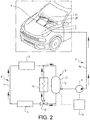
- Fig. 1 shows a vehicle 1 and a washer fluid arrangement 2 for the vehicle 1.
- the vehicle 1 comprises a component 3, such as an engine for instance, and a cooling system 4.
- the cooling system 4 has a pipe circuit 5 for circulating a coolant for cooling the component 3. Further, the cooling system 4 suitably has a heat exchanger 6, such as a radiator, for removing heat from the coolant.
- the cooling system 4 may be an engine cooling system as exemplified in Fig. 1 or a cooling system for another component of the vehicle.
- the cooling system 4 may comprise further components not discribed herein.
- the washer fluid arrangement 2 has one or more nozzles 7 for spraying washer fluid 20 on the vehicle 1.
- the nozzle 7 can be arranged to direct washer fluid towards a windshield 21 or a headlamp of the vehicle 1.
- the washer fluid arrangement 2 comprises a connecting means 8 by which connecting means the cooling system 4 of the vehicle 1 and the nozzle 7 are fluidly connectable to each other for spraying coolant as washer fluid 20 on the vehicle 1 by means of the nozzle 7.
- the connecting means 8 may comprise a pipe and/or a valve and/or a pipe connector arranged to connect the cooling system 4 and the nozzle 7 for achieving fluid communication between the cooling system 4 and the nozzle 7.
- the washer fluid arrangement 2 may comprise pump 9 for pumping coolant from the cooling system 4 to the nozzle 7.
- the washer fluid arrangement 2 comprises a pipe portion 10 arranged to extend from the pipe circuit 5 to the nozzle 7.
- the pump 9 is arranged for pumping coolant from the pipe circuit 5 to the pipe portion 10 and further to the nozzle 7.
- the connecting means 8 can comprise a reservoir 12 for coolant which reservoir is fluidly connectable to the cooling system 4 and to the nozzle 7.
- the coolant reservoir 12 is preferably a coolant expansion reservoir 12 for the cooling system 4 which reservoir is fluidly connected to the pipe circuit 5 of the cooling system 4.
- the coolant reservoir 12 has suitably a pipe connector 13 for connection to the nozzle 7. By means of the pipe connector 13, the coolant reservoir 12 can be directly connected to the nozzle or to another component which in turn is connected to the nozzle 7. In the example embodiment illustrated in Fig. 1 , the coolant reservoir 12 is connected to the pipe portion 10 extending to the nozzle 7.
- the volume of the coolant reservoir 12 is suitably adapted to the cooling system 4 as well as to the washer fluid arrangement 2 enabling the coolant reservoir to be a combined coolant expansion reservoir and a washer fluid tank.
- the washer fluid arrangement 2 preferably comprises a control unit 14 for controlling spraying of washer fluid.
- the control unit 14 is configured to allow spraying of coolant provided by the cooling system 4 as washer fluid, provided that the amount of coolant in the cooling system is above a predetermined threshold value.
- the control unit 14 can be configured to allow spraying of coolant provided by the cooling system 4 as washer fluid, provided that the level of coolant in the coolant reservoir 12 is above a predetermined threshold value.
- control unit 14 is configured to control the pump 9 such that coolant can be pumped from the cooling system 4 to the nozzle 7 provided that the amount of coolant in the cooling system 4 is above a predetermined threshold value.
- Fig. 2 shows the vehicle 1 with a variant of the cooling system illustrated in Fig. 1 .
- the coolant will often have a temperature suitable for providing a hot washer or wiper fluid, since the coolant will be heated by the component 3, even if heat generated by the component 3 also is transferred from the coolant to another fluid or air by the heat exchanger 6.
- the component 3 can be an internal combustion engine.
- the coolant will be heated only during operation of the internal combustion engine.
- the temperature of the coolant may optionally be increased by a heater in order to improve the efficiency of the washer fluid.
- the temperature of the coolant suitable for washer fluid will be maintained without any impact from the heater.
- the vehicle 1 may comprise a heater 15.
- the heater 15 is arranged for pre-heating the coolant before the coolant has reached the desired temperature.
- the heater 15 can be an electric or fuel operated supplemental heater.
- the heater 15 can be used also for other heating purposes of the vehicle 1.
- the cooling system 4' suitably comprises a valve 16 for directing coolant to the heater 15 instead of the heat exchanger 6 during pre-heating of the coolant, making it possible to heat the coolant by the heater 15 when no or insufficient heat is transferred from the component 3 to the coolant and no or negligible cooling of the component 3 is required.
- the heater 15 can be disconnected by the valve 16, and the coolant is then instead circulated from the coolant reservoir 12 to the heat exchanger 6 and further to the component 3 for cooling the component 3.
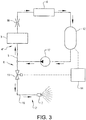
- Fig. 3 shows another example embodiment of the cooling system 4" and the washer fluid arrangement 2' of the vehicle (not shown), where a relatively high pressure of the coolant in the cooling system 4" is used for providing coolant to the nozzle 7.
- the cooling system 4" has a pump 17 for circulating the coolant in the pipe circuit 5. The circulation direction is from the coolant expansion reservoir 12 to the component 3 and further to the heat exchanger 6. Between the component 3 and the heat exchanger 6 a throttle valve 18 is arranged in the pipe circuit 5.
- the connecting means 8' of the washer fluid arrangement 2' comprises the pipe portion 10 and a valve 11.
- the pipe portion 10 extends from the pipe circuit 5 of the cooling system 4" to the valve 11 and further to the nozzle 7.
- the valve 11 is arranged for opening/closing the fluid communication between the cooling system 4 and the nozzle 7.
- the control unit 14 can be arranged to control the valve 11 for allowing coolant to be transported to the nozzle 7.
- a washer fluid pump can be omitted.
- Fig. 4 is a flow chart of one example embodiment of the method according to the invention.
- the method is used for providing washer fluid of a vehicle comprising the step of spraying coolant from a cooling system of the vehicle as washer fluid.
- Figs. 1 , 2 and 3 Reference is also made to Figs. 1 , 2 and 3 with respect to the system components mentioned when describing the method.
- a first step 100 the control unit 14 receives a request for spraying washer fluid 20.
- a second step 200 it is checked if the amount of coolant in the cooling system 4 is above a predetermined threshold value. For example, the level of coolant in the coolant reservoir 12 of the vehicle 1 has to be above a predetermined threshold value. If “YES”, then in a third step 300 the control unit 14 allows spraying of coolant as washer fluid through the nozzle 7.
- the control unit 14 is suitably arranged to control the pump 9 ( Fig. 1 ) of the pipe portion 10, or the valve 11 ( Fig. 3 ), for providing the coolant from the cooling system 4 to the nozzle 7. Otherwise, if "NO", no washer fluid from the cooling system 4 can be provided until additional coolant has been supplied to the cooling system 4 such that the amount of coolant in the cooling system 4 is above the pre-determined threshold value.
Landscapes
- Engineering & Computer Science (AREA)
- Water Supply & Treatment (AREA)
- Mechanical Engineering (AREA)
- Cooling, Air Intake And Gas Exhaust, And Fuel Tank Arrangements In Propulsion Units (AREA)
Abstract
The invention relates to a washer fluid arrangement (2) for a vehicle (1). The arrangement comprises a nozzle (7) for spraying washer fluid on the vehicle. The arrangement further comprises a connecting means (8) by which connecting means a cooling system (4) of the vehicle and the nozzle (7) are fluidly connectable to each other, for spraying coolant provided by the cooling system (4) as washer fluid (20) on the vehicle (1) by means of the nozzle (7).
Description
- The invention relates to a washer fluid arrangement for a vehicle, and a method for providing washer fluid of a vehicle.
- Vehicles usually have a washer fluid arrangement for providing washer fluid to a windshield or a headlamp of the vehicle.
- For improving the effectiveness of the washer fluid a heating system for heating the washer fluid can be used. Such a heating system which heats the washer fluid electrically or by heat exchange from an engine coolant requires additional components and an increased packing space in the engine compartment.
- An objective of the invention is to provide a washer fluid arrangement, by which arrangement washer fluid of relatively high temperature can be provided at the same time as the packing space and number of components required can be reduced.
- The objective is achieved by a washer fluid arrangement for a vehicle, wherein the arrangement comprises a nozzle for spraying washer fluid on the vehicle, and the arrangement comprises a connecting means by which connecting means a cooling system of the vehicle and the nozzle are fluidly connectable to each other, for spraying coolant provided by the cooling system as washer fluid on the vehicle by means of the nozzle.
- The invention is based on the insight that by such washer fluid arrangement, a fluid already heated by a component of the vehicle can be used as washer fluid. Hereby a cost-effective design for providing heated washer fluid can be achieved.
- For example, coolant from an engine cooling system can be used as washer fluid, such as coolant used in cooling systems for cooling an internal combustion engine or an electric motor, but also coolant of other cooling systems of a vehicle, such as coolant for cooling batteries, electrical components or computers, can be used.
- The coolant can be any liquid suitably both for a cooling system and a washer fluid arrangement. The coolant should preferably be able to withstand high temperatures, lower the freezing point and provide washing properties required for cleaning a windshield. One example of such a liquid is propylene glycol. Other possible liquids are glycerol and ethanol.
- According to one embodiment of the washer fluid arrangement, the connecting means comprises a reservoir for coolant which reservoir is fluidly connectable to the cooling system and to the nozzle. Hereby, the nozzle can be connected to the cooling system in a rational and non-complicated way.
- The reservoir is preferably a coolant expansion reservoir for the cooling system. Hereby, the number of reservoirs required can be reduced, since the coolant expansion reservoir connectable to the nozzle can replace both a conventional coolant expansion reservoir and a washer fluid tank.
- The reservoir can have a pipe-connector for connection to the nozzle. The pipe connector can be directly connectable to the nozzle or connectable to a pipe circuit extending to the nozzle or to a pump which in turn is connected to the nozzle.
- According to a further embodiment, the arrangement comprises a pump for pumping coolant from the cooling system to the nozzle. Hereby, coolant can be transported from the cooling system to the nozzle. The pump can be arranged between a reservoir for coolant of the cooling system and the nozzle. For example, the pump can be arranged in a pipe circuit connecting the reservoir and the nozzle.
- According to a further embodiment, the arrangement comprises a control unit for controlling spraying of washer fluid, and the control unit is configured to allow spraying of coolant provided by the cooling system as washer fluid, provided that the amount of coolant in the cooling system is above a predetermined threshold value. Hereby, coolant can be used as washer fluid as long as the amount of coolant in the cooling system is sufficient at the same time as the cooling capability is secured.
- For example, spraying of coolant provided by the cooling system as washer fluid can be allowed provided that the level of coolant in a coolant reservoir is above a predetermined threshold value. The control unit is preferably configured to control a pump such that coolant can be pumped from the cooling system to the nozzle provided that the amount of coolant in the cooling system is above a predetermined threshold value.
- According to further aspects of the invention, further objectives are to provide a cooling system for a vehicle, a vehicle and a method for providing washer fluid of a vehicle.
- The advantages of the cooling system, vehicle and the method are substantially the same as the advantages already discussed hereinabove with reference to the different embodiments of the washer fluid arrangement.
- Further advantages and advantageous features of the invention are disclosed in the following description and in the claims.
- With reference to the appended drawings, below follows a more detailed description of embodiments of the invention cited as examples.
- In the drawings:
-
Fig. 1 is a schematic view showing a vehicle with a cooling system and a washer fluid arrangement, -
Fig. 2 is a variant of the cooling system illustrated inFig. 1 , -
Fig. 3 is a schematic view showing another embodiment of a cooling system and a washer fluid arrangement for a vehicle, and -
Fig. 4 is a flow chart of a method for providing washer fluid of a vehicle. -
Fig. 1 shows avehicle 1 and awasher fluid arrangement 2 for thevehicle 1. Thevehicle 1 comprises acomponent 3, such as an engine for instance, and acooling system 4. Thecooling system 4 has apipe circuit 5 for circulating a coolant for cooling thecomponent 3. Further, thecooling system 4 suitably has aheat exchanger 6, such as a radiator, for removing heat from the coolant. Thecooling system 4 may be an engine cooling system as exemplified inFig. 1 or a cooling system for another component of the vehicle. Thecooling system 4 may comprise further components not discribed herein. - The
washer fluid arrangement 2 has one ormore nozzles 7 for sprayingwasher fluid 20 on thevehicle 1. Thenozzle 7 can be arranged to direct washer fluid towards awindshield 21 or a headlamp of thevehicle 1. - The
washer fluid arrangement 2 comprises aconnecting means 8 by which connecting means thecooling system 4 of thevehicle 1 and thenozzle 7 are fluidly connectable to each other for spraying coolant aswasher fluid 20 on thevehicle 1 by means of thenozzle 7. Theconnecting means 8 may comprise a pipe and/or a valve and/or a pipe connector arranged to connect thecooling system 4 and thenozzle 7 for achieving fluid communication between thecooling system 4 and thenozzle 7. - Further, the
washer fluid arrangement 2 may comprisepump 9 for pumping coolant from thecooling system 4 to thenozzle 7. In the example embodiment illustrated inFig. 1 , thewasher fluid arrangement 2 comprises apipe portion 10 arranged to extend from thepipe circuit 5 to thenozzle 7. Thepump 9 is arranged for pumping coolant from thepipe circuit 5 to thepipe portion 10 and further to thenozzle 7. - The connecting
means 8 can comprise areservoir 12 for coolant which reservoir is fluidly connectable to thecooling system 4 and to thenozzle 7. Thecoolant reservoir 12 is preferably acoolant expansion reservoir 12 for thecooling system 4 which reservoir is fluidly connected to thepipe circuit 5 of thecooling system 4. Thecoolant reservoir 12 has suitably apipe connector 13 for connection to thenozzle 7. By means of thepipe connector 13, thecoolant reservoir 12 can be directly connected to the nozzle or to another component which in turn is connected to thenozzle 7. In the example embodiment illustrated inFig. 1 , thecoolant reservoir 12 is connected to thepipe portion 10 extending to thenozzle 7. - The volume of the
coolant reservoir 12 is suitably adapted to thecooling system 4 as well as to thewasher fluid arrangement 2 enabling the coolant reservoir to be a combined coolant expansion reservoir and a washer fluid tank. - The
washer fluid arrangement 2 preferably comprises acontrol unit 14 for controlling spraying of washer fluid. Thecontrol unit 14 is configured to allow spraying of coolant provided by thecooling system 4 as washer fluid, provided that the amount of coolant in the cooling system is above a predetermined threshold value. For example, thecontrol unit 14 can be configured to allow spraying of coolant provided by thecooling system 4 as washer fluid, provided that the level of coolant in thecoolant reservoir 12 is above a predetermined threshold value. - In the example embodiment illustrated in
Fig. 1 , thecontrol unit 14 is configured to control thepump 9 such that coolant can be pumped from thecooling system 4 to thenozzle 7 provided that the amount of coolant in thecooling system 4 is above a predetermined threshold value. -
Fig. 2 shows thevehicle 1 with a variant of the cooling system illustrated inFig. 1 . As previously mentioned, the coolant will often have a temperature suitable for providing a hot washer or wiper fluid, since the coolant will be heated by thecomponent 3, even if heat generated by thecomponent 3 also is transferred from the coolant to another fluid or air by theheat exchanger 6. - As an example, the
component 3 can be an internal combustion engine. In such a case, the coolant will be heated only during operation of the internal combustion engine. Before a cold start of the internal combustion engine, the temperature of the coolant may optionally be increased by a heater in order to improve the efficiency of the washer fluid. As soon as the internal combustion engine has been running for a while, the temperature of the coolant suitable for washer fluid will be maintained without any impact from the heater. - As illustrated in
Fig. 2 , thevehicle 1 may comprise aheater 15. Theheater 15 is arranged for pre-heating the coolant before the coolant has reached the desired temperature. Theheater 15 can be an electric or fuel operated supplemental heater. Theheater 15 can be used also for other heating purposes of thevehicle 1. The cooling system 4' suitably comprises avalve 16 for directing coolant to theheater 15 instead of theheat exchanger 6 during pre-heating of the coolant, making it possible to heat the coolant by theheater 15 when no or insufficient heat is transferred from thecomponent 3 to the coolant and no or negligible cooling of thecomponent 3 is required. After the pre-heating has been performed, theheater 15 can be disconnected by thevalve 16, and the coolant is then instead circulated from thecoolant reservoir 12 to theheat exchanger 6 and further to thecomponent 3 for cooling thecomponent 3. -
Fig. 3 shows another example embodiment of thecooling system 4" and the washer fluid arrangement 2' of the vehicle (not shown), where a relatively high pressure of the coolant in thecooling system 4" is used for providing coolant to thenozzle 7. Thecooling system 4" has apump 17 for circulating the coolant in thepipe circuit 5. The circulation direction is from thecoolant expansion reservoir 12 to thecomponent 3 and further to theheat exchanger 6. Between thecomponent 3 and the heat exchanger 6 athrottle valve 18 is arranged in thepipe circuit 5. - The connecting means 8' of the washer fluid arrangement 2' comprises the
pipe portion 10 and avalve 11. Thepipe portion 10 extends from thepipe circuit 5 of thecooling system 4" to thevalve 11 and further to thenozzle 7. Thevalve 11 is arranged for opening/closing the fluid communication between thecooling system 4 and thenozzle 7. Then, thecontrol unit 14 can be arranged to control thevalve 11 for allowing coolant to be transported to thenozzle 7. Hereby, a washer fluid pump can be omitted. -
Fig. 4 is a flow chart of one example embodiment of the method according to the invention. The method is used for providing washer fluid of a vehicle comprising the step of spraying coolant from a cooling system of the vehicle as washer fluid. Reference is also made toFigs. 1 ,2 and3 with respect to the system components mentioned when describing the method. - In a
first step 100 thecontrol unit 14 receives a request for sprayingwasher fluid 20. In asecond step 200, it is checked if the amount of coolant in thecooling system 4 is above a predetermined threshold value. For example, the level of coolant in thecoolant reservoir 12 of thevehicle 1 has to be above a predetermined threshold value. If "YES", then in athird step 300 thecontrol unit 14 allows spraying of coolant as washer fluid through thenozzle 7. Thecontrol unit 14 is suitably arranged to control the pump 9 (Fig. 1 ) of thepipe portion 10, or the valve 11 (Fig. 3 ), for providing the coolant from thecooling system 4 to thenozzle 7. Otherwise, if "NO", no washer fluid from thecooling system 4 can be provided until additional coolant has been supplied to thecooling system 4 such that the amount of coolant in thecooling system 4 is above the pre-determined threshold value. - It is to be understood that the present invention is not limited to the embodiments described above and illustrated in the drawings; rather, the skilled person will recognize that many changes and modifications may be made within the scope of the appended claims.
Claims (15)
- A washer fluid arrangement (2) for a vehicle (1), the arrangement (2) comprising a nozzle (7) for spraying washer fluid (20) on the vehicle, characterized in that the arrangement (2) comprises a connecting means (8) by which connecting means a cooling system (4) of the vehicle and the nozzle (7) are fluidly connectable to each other, for spraying coolant provided by the cooling system (4) as washer fluid (20) on the vehicle (1) by means of the nozzle (5).
- An arrangement according to claim 1, characterized in that the connecting means (8) comprises a reservoir (12) for coolant which reservoir is fluidly connectable to the cooling system (4) and to the nozzle (7).
- An arrangement according to claim 2, characterized in that the coolant reservoir (12) has a pipe connector (13) for connection to the nozzle (7).
- An arrangement according to claim 2 or 3, characterized in that the coolant reservoir is a coolant expansion reservoir (12) for the cooling system (4).
- An arrangement according to any preceding claim, characterized in that the arrangement (2) comprises a pump (9) for pumping coolant from the cooling system (4) to the nozzle (7).
- An arrangement according to any preceding claim, characterized in that the arrangement (2) comprises a control unit (14) for controlling spraying of washer fluid (20), the control unit (14) being configured to allow spraying of coolant provided by the cooling system (4) as washer fluid, provided that the amount of coolant in the cooling system (4) is above a predetermined threshold value.
- An arrangement according to claim 2 and 6, characterized in that the control unit (14) is configured to allow spraying of coolant provided by the cooling system (4) as washer fluid (20), provided that the level of coolant in the coolant reservoir (12) is above a predetermined threshold value.
- An arrangement according to claim 5 and 6, characterized in that the control unit (14) is configured to control the pump (9) such that coolant can be pumped from the cooling system (4) to the nozzle (7) provided that the amount of coolant in the cooling system is above a predetermined threshold value.
- An arrangement according to any preceding claim, characterized in that an engine cooling system (4) of the vehicle (1) and the nozzle (7) are fluidly connectable to each other by the connecting means (8).
- A cooling system (4) for a vehicle, the system comprising a pipe circuit (5) for circulating a coolant for cooling a component (3) of the vehicle (1), characterized in that the pipe circuit (5) is fluidly connectable to a nozzle (7) of the vehicle for spraying coolant as washer fluid (20) on the vehicle (1).
- A vehicle (1) comprising a component (3) and a cooling system (4), the cooling system having a pipe circuit (5) for circulating a coolant for cooling the component (3), the vehicle (1) further comprising a washer fluid arrangement (2) having a nozzle (7) for spraying washer fluid on the vehicle, characterized in that the vehicle (1) comprises a connecting means (8) by which connecting means the cooling system (4) of the vehicle and the nozzle (7) are fluidly connectable to each other for spraying coolant as washer fluid (20) on the vehicle (1).
- A vehicle according to claim 11, characterized in that the vehicle (1) comprises a coolant expansion reservoir (12) fluidly connected to the pipe circuit (5), the coolant expansion reservoir (12) being fluidly connectable to the nozzle (7).
- A vehicle according to claim 11 or 12, characterized in that the nozzle (7) is arranged to direct washer fluid towards a windshield (21) or a headlamp of the vehicle (1).
- A vehicle according to any of claims 11-13, characterized in that the vehicle (1) comprises a heater (15) arranged for heating the coolant.
- A method for providing washer fluid of a vehicle (1), characterized by spraying coolant from a cooling system (4) of the vehicle (1) as washer fluid (20).
Priority Applications (1)
| Application Number | Priority Date | Filing Date | Title |
|---|---|---|---|
| EP19165259.3A EP3715192A1 (en) | 2019-03-26 | 2019-03-26 | A washer fluid arrangement |
Applications Claiming Priority (1)
| Application Number | Priority Date | Filing Date | Title |
|---|---|---|---|
| EP19165259.3A EP3715192A1 (en) | 2019-03-26 | 2019-03-26 | A washer fluid arrangement |
Publications (1)
| Publication Number | Publication Date |
|---|---|
| EP3715192A1 true EP3715192A1 (en) | 2020-09-30 |
Family
ID=65991648
Family Applications (1)
| Application Number | Title | Priority Date | Filing Date |
|---|---|---|---|
| EP19165259.3A Withdrawn EP3715192A1 (en) | 2019-03-26 | 2019-03-26 | A washer fluid arrangement |
Country Status (1)
| Country | Link |
|---|---|
| EP (1) | EP3715192A1 (en) |
Cited By (1)
| Publication number | Priority date | Publication date | Assignee | Title |
|---|---|---|---|---|
| JP2024047801A (en) * | 2022-09-27 | 2024-04-08 | いすゞ自動車株式会社 | Cooling System |
Citations (5)
| Publication number | Priority date | Publication date | Assignee | Title |
|---|---|---|---|---|
| JPS5078834U (en) * | 1973-11-21 | 1975-07-08 | ||
| JPS5643451U (en) * | 1979-09-12 | 1981-04-20 | ||
| DE19534108A1 (en) * | 1995-09-14 | 1997-03-20 | Wilo Gmbh | Cooling system for internal combustion engine |
| WO2005125295A2 (en) * | 2004-06-17 | 2005-12-29 | Avl List Gmbh | Device for cooling at least one electrical and/or electronic power component |
| EP2196367A1 (en) * | 2008-12-10 | 2010-06-16 | Peugeot Citroen Automobiles SA | Washing liquid tank, in particular for windows or projectors of a vehicle |
-
2019
- 2019-03-26 EP EP19165259.3A patent/EP3715192A1/en not_active Withdrawn
Patent Citations (5)
| Publication number | Priority date | Publication date | Assignee | Title |
|---|---|---|---|---|
| JPS5078834U (en) * | 1973-11-21 | 1975-07-08 | ||
| JPS5643451U (en) * | 1979-09-12 | 1981-04-20 | ||
| DE19534108A1 (en) * | 1995-09-14 | 1997-03-20 | Wilo Gmbh | Cooling system for internal combustion engine |
| WO2005125295A2 (en) * | 2004-06-17 | 2005-12-29 | Avl List Gmbh | Device for cooling at least one electrical and/or electronic power component |
| EP2196367A1 (en) * | 2008-12-10 | 2010-06-16 | Peugeot Citroen Automobiles SA | Washing liquid tank, in particular for windows or projectors of a vehicle |
Cited By (2)
| Publication number | Priority date | Publication date | Assignee | Title |
|---|---|---|---|---|
| JP2024047801A (en) * | 2022-09-27 | 2024-04-08 | いすゞ自動車株式会社 | Cooling System |
| DE102023122043B4 (en) * | 2022-09-27 | 2025-07-24 | Isuzu Motors Limited | COOLING SYSTEM |
Similar Documents
| Publication | Publication Date | Title |
|---|---|---|
| CN112238727B (en) | Thermal management system for vehicle and integrated thermal management module | |
| US10549605B2 (en) | Heating system and method for heating a vehicle interior of a vehicle having an internal combustion engine | |
| US4932365A (en) | System for evaporation cooling of an internal combustion engine and for operation of a heating heat exchanger by the coolant | |
| CN106499497B (en) | Adapter for engine cooling system | |
| JP2019504965A (en) | A system for storing auxiliary fluid and supplying it to an internal combustion engine | |
| CN110234853A (en) | Method for operating the hybrid electric vehicle cooling system including liquid coolant transmitting circuit | |
| CN110872981A (en) | Cooling system for an internal combustion engine of a motor vehicle | |
| KR20200136043A (en) | A heat management system for a hybrid motor vehicle | |
| EP3715192A1 (en) | A washer fluid arrangement | |
| US6595432B2 (en) | Heating system for heating the passenger compartment of an automobile | |
| JP2018119423A (en) | Engine cooling system | |
| CN1168619C (en) | Heating system for heating the interior of a car | |
| CN201694024U (en) | Engine low temperature start preheating and cab heating system | |
| KR102506945B1 (en) | Cooling system of hybrid electric vehicle | |
| CN111591126A (en) | Electric automobile radiator cooling system, control method thereof and electric automobile | |
| US9074779B2 (en) | Distribution module for water heater | |
| US20190048793A1 (en) | System for storing and delivering an auxiliary liquid to an internal combustion engine of a motor vehicle or to parts of the internal combustion engine of the motor vehicle | |
| CN108138642A (en) | Shutdown cooling system, cylinder head, and method for operating shutdown cooling system | |
| US9561716B2 (en) | Cooling of an electric motor via heat pipes | |
| KR100405537B1 (en) | an apparatus for air removal and coolant replenishment in a cooling system of vehicles | |
| US6862518B2 (en) | Method for monitoring a coolant circuit of an internal combustion engine | |
| US10598078B2 (en) | Method and apparatus for active coolant volume reduction for automobile applications | |
| CN111391651B (en) | Pressure regulator preheating system for transport refrigeration unit | |
| US20060032844A1 (en) | Vehicle coolant heating system | |
| CA2482104C (en) | Distribution module for water heater |
Legal Events
| Date | Code | Title | Description |
|---|---|---|---|
| PUAI | Public reference made under article 153(3) epc to a published international application that has entered the european phase |
Free format text: ORIGINAL CODE: 0009012 |
|
| STAA | Information on the status of an ep patent application or granted ep patent |
Free format text: STATUS: REQUEST FOR EXAMINATION WAS MADE |
|
| 17P | Request for examination filed |
Effective date: 20190326 |
|
| AK | Designated contracting states |
Kind code of ref document: A1 Designated state(s): AL AT BE BG CH CY CZ DE DK EE ES FI FR GB GR HR HU IE IS IT LI LT LU LV MC MK MT NL NO PL PT RO RS SE SI SK SM TR |
|
| AX | Request for extension of the european patent |
Extension state: BA ME |
|
| STAA | Information on the status of an ep patent application or granted ep patent |
Free format text: STATUS: THE APPLICATION IS DEEMED TO BE WITHDRAWN |
|
| 18D | Application deemed to be withdrawn |
Effective date: 20210331 |