EP3715170A1 - Autonomous driving work machine and system - Google Patents
Autonomous driving work machine and system Download PDFInfo
- Publication number
- EP3715170A1 EP3715170A1 EP20158967.8A EP20158967A EP3715170A1 EP 3715170 A1 EP3715170 A1 EP 3715170A1 EP 20158967 A EP20158967 A EP 20158967A EP 3715170 A1 EP3715170 A1 EP 3715170A1
- Authority
- EP
- European Patent Office
- Prior art keywords
- power receiving
- pair
- charging station
- terminals
- work machine
- Prior art date
- Legal status (The legal status is an assumption and is not a legal conclusion. Google has not performed a legal analysis and makes no representation as to the accuracy of the status listed.)
- Granted
Links
Images


Classifications
-
- B—PERFORMING OPERATIONS; TRANSPORTING
- B60—VEHICLES IN GENERAL
- B60L—PROPULSION OF ELECTRICALLY-PROPELLED VEHICLES; SUPPLYING ELECTRIC POWER FOR AUXILIARY EQUIPMENT OF ELECTRICALLY-PROPELLED VEHICLES; ELECTRODYNAMIC BRAKE SYSTEMS FOR VEHICLES IN GENERAL; MAGNETIC SUSPENSION OR LEVITATION FOR VEHICLES; MONITORING OPERATING VARIABLES OF ELECTRICALLY-PROPELLED VEHICLES; ELECTRIC SAFETY DEVICES FOR ELECTRICALLY-PROPELLED VEHICLES
- B60L53/00—Methods of charging batteries, specially adapted for electric vehicles; Charging stations or on-board charging equipment therefor; Exchange of energy storage elements in electric vehicles
- B60L53/10—Methods of charging batteries, specially adapted for electric vehicles; Charging stations or on-board charging equipment therefor; Exchange of energy storage elements in electric vehicles characterised by the energy transfer between the charging station and the vehicle
- B60L53/14—Conductive energy transfer
- B60L53/16—Connectors, e.g. plugs or sockets, specially adapted for charging electric vehicles
-
- B—PERFORMING OPERATIONS; TRANSPORTING
- B60—VEHICLES IN GENERAL
- B60L—PROPULSION OF ELECTRICALLY-PROPELLED VEHICLES; SUPPLYING ELECTRIC POWER FOR AUXILIARY EQUIPMENT OF ELECTRICALLY-PROPELLED VEHICLES; ELECTRODYNAMIC BRAKE SYSTEMS FOR VEHICLES IN GENERAL; MAGNETIC SUSPENSION OR LEVITATION FOR VEHICLES; MONITORING OPERATING VARIABLES OF ELECTRICALLY-PROPELLED VEHICLES; ELECTRIC SAFETY DEVICES FOR ELECTRICALLY-PROPELLED VEHICLES
- B60L53/00—Methods of charging batteries, specially adapted for electric vehicles; Charging stations or on-board charging equipment therefor; Exchange of energy storage elements in electric vehicles
- B60L53/30—Constructional details of charging stations
- B60L53/35—Means for automatic or assisted adjustment of the relative position of charging devices and vehicles
- B60L53/36—Means for automatic or assisted adjustment of the relative position of charging devices and vehicles by positioning the vehicle
-
- G—PHYSICS
- G05—CONTROLLING; REGULATING
- G05D—SYSTEMS FOR CONTROLLING OR REGULATING NON-ELECTRIC VARIABLES
- G05D1/00—Control of position, course, altitude or attitude of land, water, air or space vehicles, e.g. using automatic pilots
- G05D1/02—Control of position or course in two dimensions
- G05D1/021—Control of position or course in two dimensions specially adapted to land vehicles
- G05D1/0212—Control of position or course in two dimensions specially adapted to land vehicles with means for defining a desired trajectory
- G05D1/0225—Control of position or course in two dimensions specially adapted to land vehicles with means for defining a desired trajectory involving docking at a fixed facility, e.g. base station or loading bay
-
- H—ELECTRICITY
- H02—GENERATION; CONVERSION OR DISTRIBUTION OF ELECTRIC POWER
- H02J—ELECTRIC POWER NETWORKS; CIRCUIT ARRANGEMENTS OR SYSTEMS FOR SUPPLYING OR DISTRIBUTING ELECTRIC POWER; SYSTEMS FOR STORING ELECTRIC ENERGY
- H02J7/00—Circuit arrangements for charging or discharging batteries or for supplying loads from batteries
- H02J7/70—Circuit arrangements for charging or discharging batteries or for supplying loads from batteries characterised by the mechanical construction
- H02J7/751—Circuit arrangements for charging or discharging batteries or for supplying loads from batteries characterised by the mechanical construction concerning the insertion or the connection of the batteries
-
- B—PERFORMING OPERATIONS; TRANSPORTING
- B60—VEHICLES IN GENERAL
- B60L—PROPULSION OF ELECTRICALLY-PROPELLED VEHICLES; SUPPLYING ELECTRIC POWER FOR AUXILIARY EQUIPMENT OF ELECTRICALLY-PROPELLED VEHICLES; ELECTRODYNAMIC BRAKE SYSTEMS FOR VEHICLES IN GENERAL; MAGNETIC SUSPENSION OR LEVITATION FOR VEHICLES; MONITORING OPERATING VARIABLES OF ELECTRICALLY-PROPELLED VEHICLES; ELECTRIC SAFETY DEVICES FOR ELECTRICALLY-PROPELLED VEHICLES
- B60L2260/00—Operating Modes
- B60L2260/20—Drive modes; Transition between modes
- B60L2260/32—Auto pilot mode
-
- B—PERFORMING OPERATIONS; TRANSPORTING
- B60—VEHICLES IN GENERAL
- B60L—PROPULSION OF ELECTRICALLY-PROPELLED VEHICLES; SUPPLYING ELECTRIC POWER FOR AUXILIARY EQUIPMENT OF ELECTRICALLY-PROPELLED VEHICLES; ELECTRODYNAMIC BRAKE SYSTEMS FOR VEHICLES IN GENERAL; MAGNETIC SUSPENSION OR LEVITATION FOR VEHICLES; MONITORING OPERATING VARIABLES OF ELECTRICALLY-PROPELLED VEHICLES; ELECTRIC SAFETY DEVICES FOR ELECTRICALLY-PROPELLED VEHICLES
- B60L2260/00—Operating Modes
- B60L2260/40—Control modes
-
- Y—GENERAL TAGGING OF NEW TECHNOLOGICAL DEVELOPMENTS; GENERAL TAGGING OF CROSS-SECTIONAL TECHNOLOGIES SPANNING OVER SEVERAL SECTIONS OF THE IPC; TECHNICAL SUBJECTS COVERED BY FORMER USPC CROSS-REFERENCE ART COLLECTIONS [XRACs] AND DIGESTS
- Y02—TECHNOLOGIES OR APPLICATIONS FOR MITIGATION OR ADAPTATION AGAINST CLIMATE CHANGE
- Y02T—CLIMATE CHANGE MITIGATION TECHNOLOGIES RELATED TO TRANSPORTATION
- Y02T10/00—Road transport of goods or passengers
- Y02T10/60—Other road transportation technologies with climate change mitigation effect
- Y02T10/70—Energy storage systems for electromobility, e.g. batteries
-
- Y—GENERAL TAGGING OF NEW TECHNOLOGICAL DEVELOPMENTS; GENERAL TAGGING OF CROSS-SECTIONAL TECHNOLOGIES SPANNING OVER SEVERAL SECTIONS OF THE IPC; TECHNICAL SUBJECTS COVERED BY FORMER USPC CROSS-REFERENCE ART COLLECTIONS [XRACs] AND DIGESTS
- Y02—TECHNOLOGIES OR APPLICATIONS FOR MITIGATION OR ADAPTATION AGAINST CLIMATE CHANGE
- Y02T—CLIMATE CHANGE MITIGATION TECHNOLOGIES RELATED TO TRANSPORTATION
- Y02T10/00—Road transport of goods or passengers
- Y02T10/60—Other road transportation technologies with climate change mitigation effect
- Y02T10/7072—Electromobility specific charging systems or methods for batteries, ultracapacitors, supercapacitors or double-layer capacitors
-
- Y—GENERAL TAGGING OF NEW TECHNOLOGICAL DEVELOPMENTS; GENERAL TAGGING OF CROSS-SECTIONAL TECHNOLOGIES SPANNING OVER SEVERAL SECTIONS OF THE IPC; TECHNICAL SUBJECTS COVERED BY FORMER USPC CROSS-REFERENCE ART COLLECTIONS [XRACs] AND DIGESTS
- Y02—TECHNOLOGIES OR APPLICATIONS FOR MITIGATION OR ADAPTATION AGAINST CLIMATE CHANGE
- Y02T—CLIMATE CHANGE MITIGATION TECHNOLOGIES RELATED TO TRANSPORTATION
- Y02T90/00—Enabling technologies or technologies with a potential or indirect contribution to GHG emissions mitigation
- Y02T90/10—Technologies relating to charging of electric vehicles
- Y02T90/12—Electric charging stations
-
- Y—GENERAL TAGGING OF NEW TECHNOLOGICAL DEVELOPMENTS; GENERAL TAGGING OF CROSS-SECTIONAL TECHNOLOGIES SPANNING OVER SEVERAL SECTIONS OF THE IPC; TECHNICAL SUBJECTS COVERED BY FORMER USPC CROSS-REFERENCE ART COLLECTIONS [XRACs] AND DIGESTS
- Y02—TECHNOLOGIES OR APPLICATIONS FOR MITIGATION OR ADAPTATION AGAINST CLIMATE CHANGE
- Y02T—CLIMATE CHANGE MITIGATION TECHNOLOGIES RELATED TO TRANSPORTATION
- Y02T90/00—Enabling technologies or technologies with a potential or indirect contribution to GHG emissions mitigation
- Y02T90/10—Technologies relating to charging of electric vehicles
- Y02T90/14—Plug-in electric vehicles
Definitions
- the present invention relates to an autonomous travel work machine and a system.
- An autonomous travel work machine which can travel to a charging station by autonomous travel.
- Japanese Patent No. 6285979 there is a known configuration in which a terminal portion that protrudes rearward is provided in a charging station, and a recessed portion (a portion between a pair of power receiving terminals) into which the terminal portion of the charging station can be inserted is provided to a robot lawn mower which is a kind of autonomous travel work machine, and inserting the terminal portion to the recessed portion electrically connect the robot lawn mower to the charging station, and the battery in the robot lawn mower is charged with the power from the charging station (for example, Japanese Patent No. 6285979 ).
- an object of the present invention is to make it possible to suppress the situation in which electrical continuity is established between a pair of power receiving terminals through moisture.
- the pair of power receiving terminals have at least a first structure in which the pair of power receiving terminals are separately disposed in different parts from among a plurality of parts constituting the autonomous travel work machine, or a second structure in which at least one of the pair of power receiving terminals has a downward-facing contact surface that comes into contact with the charging station.
- a vehicle body that has a traveling function, and a vehicle body cover that covers the vehicle body are included, and in the first structure, the pair of power receiving terminals are separately disposed in the vehicle body and the vehicle body cover.
- a recessed portion into which a part of the charging station can enter is included, and at least one of the pair of power receiving terminals is provided in the recessed portion.
- the power receiving terminal facing downward is provided in the recessed portion.
- the other power receiving terminal has a laterally facing contact surface that comes into contact with the charging station.
- the other power receiving terminal is provided below the one power receiving terminal and has an upward-facing contact surface that comes into contact with the charging station, and the part of the charging station is sandwiched between the pair of power receiving terminals from above and below.
- the pair of power receiving terminals both have downward-facing contact surfaces that come into contact with the charging station, and a draining partition member is provided between the pair of power receiving terminals.
- the pair of power receiving terminals are spaced apart along a direction in which a part of the charging station enters the recessed portion.
- a system includes the autonomous travel work machine and a charging station for the autonomous travel work machine, the charging station includes: a pair of power transmission terminals electrically connected to the pair of power receiving terminals.
- One of the pair of power transmission terminals has a contact surface that comes into contact with the power receiving terminal, the contact surface facing upward and being an inclined surface that is inclined with respect to the horizontal plane.
- a plug unit that has the pair of power transmission terminals spaced apart in the up-down direction and the horizontal direction is included, and the plug unit has an inclined surface in a region between the pair of power transmission terminals, the inclined surface draining water on the region out of the plug unit by utilizing at least gravity.
- a situation in which electrical continuity is established between a pair of power receiving terminals through moisture can be suppressed.
- FIG. 1 is a diagram showing the configuration of an automated lawn mowing system 1 according to the first embodiment.
- the automated lawn mowing system 1 includes a robot lawn mower 2, an area wire 5 that defines a lawn mowing area 4 that is a work area, and a charging station 6.
- the robot lawn mower 2 is an autonomous travel work machine that mows turf grass while automatically and autonomously running in the lawn mowing area 4 and is an example of an autonomous travel work machine or a self-propelled work machine. In the following description, the robot lawn mower 2 is referred to as "lawn mower 2".
- the area wire 5 is installed so that the lawn mower 2 detects the boundary A of the lawn mowing area 4.
- the area wire 5 is laid along the boundary A and transmits a predetermined signal, and the lawn mower 2 detects the boundary A of the lawn mowing area 4 by detecting the signal from the area wire 5.
- the charging station 6 is an apparatus that functions as a charging device for charging the lawn mower 2 as well as a standby place where the lawn mower 2 is put on standby when not working.
- the lawn mower 2 moves to the charging station 6 by autonomous travel, for example, at the end of the lawn mowing work, and is charged as appropriate with the electric power supplied from the charging station 6.
- the area wire 5 transmits a predetermined signal based on the electric power or signal supplied from the charging station 6.
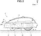
- Fig. 2 is a diagram schematically showing the configuration of a lawn mower 2.
- the lawn mower 2 includes a vehicle body 11 that has a traveling function and the like, and a vehicle body cover 21 that covers the vehicle body 11.
- Right and left front wheels 12 that can be steered to the right and left are provided at the front lower portion of the vehicle body 11, right and left rear wheels 13 that function as drive wheels are provided at the rear lower portion of the vehicle body 11, and a work unit 14 is provided at the central lower portion of the vehicle body 11.
- a terminal portion 31 that is electrically connected to the charging station 6 is provided at the front portion of the lawn mower 2. The details of the terminal portion 31 will be described later.
- the vehicle body 11 is an electric unit that includes right and left traveling motors 15 that separately drive the right and left rear wheels 13, a work unit driving motor 16 that drives the work unit 14, a battery 17 that functions as a power source that supplies operation electric power to each component of the lawn mower 2, a wheel speed sensor 18 that detects the rotational speed of the right and left rear wheels 13 serving as drive wheels, a sensor unit 19 that detects the area wire 5 and the like, and a control unit 30 that controls each component of the lawn mower 2.
- the control unit 30 controls the travel of the lawn mower 2 by controlling the driving of the traveling motor 15 and performs a predetermined operation by controlling the driving of the work unit driving motor 16.
- the work unit 14 of this embodiment is a cutting blade disc with a cutting blade, and can perform lawn mowing work when the cutting blade disc is rotated.
- the control unit 30 specifies the position of the lawn mower 2 based on the results of detection by the wheel speed sensor 18 and the sensor unit 19, and controls the travel of the lawn mower 2 based on the specified position. Hence, it can travel so that the lawn in the lawn mowing area 4 may be appropriately mowed, and can move to the charging station 6 after completion of the lawn mowing work.
- the configuration of a well-known robot lawn mower can be widely applied to the configuration of the vehicle body 11 except the terminal portion 31.
- a position detection device such as GPS or a gyro sensor, or image recognition technology using a camera, or other technology may be used as technology for specifying the lawn mowing area 4, the charging station 6, the current position, and the like.
- the vehicle body cover 21 includes a main cover 22 that covers at least the front portion of the vehicle body 11, and a top cover 23 that is coupled to the main cover 22 from above.
- the main cover 22 is formed as a cover that covers the front, rear, left, and right sides of the vehicle body 11 and opens a part of the vehicle body 11 upward, and is made of a resin material.
- the top cover 23 is formed as a cover that covers a portion where a part of the vehicle body 11 in the main cover 22 is opened, and is made of a resin material.
- These covers 22 and 23 function as a protective cover for preventing rainwater and dust from adhering to the vehicle body 11 and a decorative cover for improving the appearance.
- the material for the body cover 21 is not limited to resin.
- the main cover 22 and the top cover 23 may be integrally formed.
- Fig. 3 is a diagram showing the state in which the lawn mower 2 and a charging station 6 are electrically connected to each other.
- the vehicle body cover 21 is indicated by the two-dot chain line in FIG. 3 .
- the charging station 6 includes a connection base 51 to which the lawn mower 2 is connected, and a mounting base 52 on which the lawn mower 2 connected to the connection base 51 is mounted.
- the connection base 51 has a plug unit 53 that protrudes toward the lawn mower 2 on the mounting base 52.
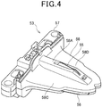
- FIG. 4 is a perspective view of the plug unit 53.
- the plug unit 53 is formed in a triangular shape that narrows toward the rear in a top view, and includes a pair of power transmission terminals 55 and 56.
- the positive-side power transmission terminal 55 is formed as a terminal that protrudes upward from the center of the plug unit 53 when viewed along the right-left direction and the intermediate position of the plug unit 53 when viewed along the front-rear direction.
- the negative-side power transmission terminal 56 is a plate-like terminal that protrudes, when viewed along the right-left direction, outward from one of the right and left surfaces of the plug unit 53 (in this embodiment, the surface on the left side of the lawn mower 2) and the tip side of the plug unit 53.
- the plug unit 53 is integrally provided with a basal section 57 connected to the connection base 51 and a unit body 58 having a triangular shape in a top view and extending from the basal section 57.
- the unit body 58 has a raised portion 58A that rises upward from the central portion when viewed along the right-left direction and that extends in the front-rear direction, and the upper surface of the raised portion 58A is inclined obliquely downward from the basal section 57 toward the tip of the unit body 58.
- the positive-side power transmission terminal 55 is disposed in a region corresponding to the raised portion 58A, with a part thereof protruding upward. For this reason, even if moisture such as rainwater adheres to the raised portion 58A, moisture can gravitationally flow out of the raised portion 58A, and rainwater does not remain around the positive-side power transmission terminal 55.
- the raised portion 58A has an opening 58B that opens upward on the tip side of the positive-side power transmission terminal 55, and this opening 58B allows moisture flowing along the slope of the raised portion 58A to quickly drop downward.
- the unit body 58 is inclined obliquely downward from the basal section 57 toward the tip of the unit body 58. For this reason, even if moisture such as rainwater adheres to the right and left upper surfaces 58C and 58D, it can quickly flow out of the unit body 58.
- the negative-side power transmission terminal 56 is provided on the side surface of the unit body 58, even if moisture such as rainwater adheres thereto, it can quickly drop gravitationally.
- the positive-side power transmission terminal 55 and the negative-side power transmission terminal 56 are spaced apart in the up-down direction, the front-rear direction, and the right-left direction. This facilitates avoidance of establishment of electrical continuity between the positive-side power transmission terminal 55 and the negative-side power transmission terminal 56 by moisture such as rainwater. Even if the grass that is attached to the lawn mower 2 and wetted with water adheres to the plug unit 53, the situation where establishment of electrical continuity between the positive-side power transmission terminal 55 and the negative-side power transmission terminal 56 by the wet grass is avoided easily.
- FIG. 5 is a diagram showing the plug unit 53 in FIG. 3 together with a part of the lawn mower 2.
- an opening 22K that allows the plug unit 53 to be inserted toward the terminal portion 31 is provided in the front surface of the main cover 22 of the lawn mower 2.
- a space 31K into which the plug unit 53 can be inserted is provided between the opening 22K and the terminal portion 31.
- the opening 22K and the space 31K define a recessed portion 2K that allows the plug unit 53, which is a part of the charging station 6, to be inserted into the terminal portion 31.
- FIG. 6 is a diagram of a terminal portion 31 viewed from the bottom of the lawn mower 2.
- the plug unit 53 inserted to the bottom of the recessed portion 2K is indicated by the two-dot chain line.
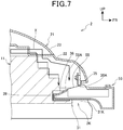
- FIG. 7 is a diagram schematically showing a sectional side view along a line passing through the central position of the plug unit 53 along the right-left direction in FIG. 3 .
- the terminal portion 31 has the positive-side power receiving terminal 35 provided on the vehicle body cover 21, the negative-side power receiving terminal 36 provided on the vehicle body 11, and a dummy terminal 37 opposed to the negative-side power receiving terminal 36.
- the positive-side power receiving terminal 35 is attached to the foremost portion of the main cover 22 and is formed of a metal plate with a downward-facing contact surface 35A (see FIG. 7 ) which is in contact with the positive-side power transmission terminal 55 of the plug unit 53.
- the positive-side power receiving terminal 35 is fixed to the rear surface of the foremost portion of the main cover 22 with a fastening member 38 (see FIG. 5 ) inserted from the front of the main cover 22, and protrudes downward from the foremost portion of the main cover 22 toward the recessed portion 2K. As shown in FIG.
- the positive-side power receiving terminal 35 is formed so that it has a U-shaped cross section that opens upward and its lower surface is the contact surface 35A that comes in contact with the upper surface of the positive-side power transmission terminal 55 of the plug unit 53 inserted in the recessed portion 2K.
- the upper surface of the positive-side power transmission terminal 55 of the plug unit 53 that is, the contact surface comes in contact with the positive-side power receiving terminal 35 is inclined downward and toward the lawn mower 2 (the bottom of the recessed portion 2K). For this reason, even if moisture such as rainwater adheres to the upper surface of the positive-side power transmission terminal 55, moisture can quickly flow out of the terminal 55 gravitationally, which facilitates avoidance of the phenomenon in which rainwater remains on the upper surface of the positive-side power transmission terminal 55.
- wet grass or raindrops may enter the recessed portion 2K of the lawn mower 2.
- the positive-side power receiving terminal 35 of the lawn mower 2 faces downward, so that wet grass or raindrops are unlikely to adhere thereto and, and even if it adheres thereto, it easily drops by gravity compared to the case where the positive-side power receiving terminal 35 faces upward.
- the positive-side power transmission terminal 55 that comes in contact with the positive-side power receiving terminal 35 is an upward inclined surface that is inclined with respect to the horizontal plane, which facilitates avoidance of the remaining moisture as described above. Further, the terminals 35 and 55 rub against each other when the terminals 35 and 55 are electrically connected to each other, which effectively generates wiping action for removing foreign matters, such as moisture, from the terminals 35 and 55.
- the negative-side power receiving terminal 36 is spaced apart from the positive-side power receiving terminal 35 in the font-rear direction and the right-left direction.
- the negative-side power receiving terminal 36 is attached to a front projecting portion 11T (see FIG. 6 ) that constitutes a part of the foremost portion of the vehicle body 11, and is, in the bottom view shown in FIG. 6 , a metal plate that curves in a U-shape from one of the right and left sides (in this embodiment, the right side in FIG. 6 ) to the other one of the right and left sides (the left side in FIG. 6 ).
- the negative-side power receiving terminal 36 is disposed in a position shifted to one of the right and left sides from the center plane M1 of the vehicle body 11 when viewed along the right and left direction (coinciding with the center plane of the lawn mower 2 when viewed along the right and left direction), and has a laterally (leftward in FIG. 6 ) facing contact surface that comes in contact with the negative-side power transmission terminal 56.
- the negative-side power receiving terminal 36 is provided in the position that overlaps with the negative-side power transmission terminal 56 of the plug unit 53 when the plug unit 53 is inserted to the position indicated by the two-dot chain line shown in FIG. 6 .
- the negative-side power receiving terminal 36 curves in a U shape and deforms so that the pressure of contact with the negative-side power transmission terminal 56 does not become excessive, thereby keeping an appropriate state of contact between the terminals 36 and 53.
- the negative-side power transmission terminal 56 side may be made deformable.
- the dummy terminal 37 facing the negative-side power receiving terminal 36 and the structure supporting the dummy terminal 37 are formed symmetrically to the negative-side power receiving terminal 36 and its peripheral structure, respectively.
- the dummy terminal 37 and its support structure are formed in positions and structures that are symmetric with respect to the center plane M1 of the vehicle body 11 when viewed along the right-left direction. Since the plug unit 53 is inserted between the dummy terminal 37 and the negative-side power receiving terminal 36, it is easy to guide the travel direction of the lawn mower 2 toward the plug unit 53 to an appropriate direction or keep an appropriate state of the contact between the negative-side power receiving terminal 36 and the negative-side power transmission terminal 56.
- the terminal portion 31 is provided with a contact portion 39 that the tip of the plug unit 53 comes in contact with.
- the contact portion 39 is provided in the position that the plug unit 53 comes in contact with when the pair of power receiving terminals 35 and 36 of the terminal portion 31 and the pair of power transmission terminals 55 and 56 of the plug unit 53 are electrically connected to each other.
- the negative-side power receiving terminal 36 of the terminal portion 31 is provided on the relatively bottom side in the recessed portion 2K, so that wet grass or raindrops are unlikely to adhere to the negative-side power receiving terminal 36.
- the negative-side power receiving terminal 36 and the positive-side power receiving terminal 35 are separately disposed in the vehicle body cover 21 and the vehicle body 11, so that the continuity route (represented by X in FIG. 7 ) straddling between the vehicle body cover 21 and the vehicle body 11 can be made long, and the movement of moisture at the boundary between the vehicle body cover 21 and the vehicle body 11 can be suppressed easily.
- the lawn mower 2 of this embodiment has a first structure in which the pair of power receiving terminals 35 and 36 are separately disposed in the vehicle body cover 21 and the vehicle body 11 which are different parts from among the plurality of parts constituting the lawn mower 2.
- the continuity route X (see FIG. 7 ) can be made long, the movement of moisture at the boundary between parts can be easily canceled, and the situation where electrical continuity is established between the pair of power receiving terminals 35 and 36 through moisture can be suppressed. Accordingly, the situation where electrical continuity is established between the pair of power transmission terminals 55 and 56 and proper charging is not achieved, and the bimetallic corrosion can be effectively suppressed.
- the pair of power receiving terminals 35 and 36 are not necessarily separately disposed in the vehicle body cover 21 and the vehicle body 11, and may be separately disposed in a plurality of other different parts constituting the lawn mower 2.
- the lawn mower 2 also has a second structure in which the power receiving terminal 35, which is one of the pair of power receiving terminals 35 and 36, has the contact surface 35A (see FIG. 7 ) which comes in contact with the charging station 6 and faces downward.
- the power receiving terminal 35 which is one of the pair of power receiving terminals 35 and 36
- the contact surface 35A see FIG. 7
- moisture and the like is unlikely to remain in the power receiving terminal 35 facing downward, which also suppresses the situation where electrical continuity is established between the pair of power receiving terminals 35 and 36 and further suppresses the situation where proper charging is not achieved.
- the other one that is, the power receiving terminal 36 may have a downward-facing contact surface that comes in contact with the charging station 6.
- the situation where electrical continuity is established between the pair of power receiving terminals 35 and 36 through moisture can be further suppressed.
- the lawn mower 2 has a recessed portion 2K into which the plug unit 53 that is a part of the charging station 6 can enter, and the pair of power receiving terminals 35 and 36 are both located in the recessed portion 2K, which also makes it difficult for moisture such as rainwater to adhere to the power receiving terminals 35 and 36, and the situation where electrical continuity is established between the power receiving terminals 35 and 36 through moisture can be suppressed. Even if only one of the power receiving terminals 35 and 36 is located in the recessed portion 2K, the situation where electrical continuity is established between the power receiving terminals 35 and 36 through moisture can be suppressed.
- the power receiving terminal 35 facing downward in the second structure is provided in the recessed portion 2K, moisture is more unlikely to adhere to the power receiving terminal 35.
- the other terminal, that is, the power receiving terminal 36 in the second structure has a laterally facing contact surface that comes in contact with the charging station 6, it is also difficult for moisture to adhere to or remain on the other terminal, that is, the power receiving terminal 36.
- one of the pair of power transmission terminals 55 and 56 provided in the charging station 6 has a contact surface that comes into contact with the power receiving terminal 36 so that the contact surface faces upward and is inclined with respect to the horizontal plane, even moisture or the like on the contact surface can be discharged quickly.
- the wiping action between the terminals 55 and 35 and between the terminals 56 and 36 can also effectively suppress the situation where moisture or the like remains.
- the charging station 6 further includes a plug unit 53 provided with a pair of power transmission terminals 55 and 56 spaced apart in the up-down direction, the horizontal direction, and the height direction.
- the plug unit 53 has an inclined surface in a region between the pair of power transmission terminals 55 and 56, and the inclined surface drains the moisture on the region out of the plug unit 53 by utilizing at least gravity. Hence, it is possible to suppress the situation where moisture or the like remains on the power transmission terminals 55 and 56 and their periphery.
- FIG. 8 is a diagram schematically showing a sectional side view in the state in which the lawn mower 2 and the plug unit 53 in the automated lawn mowing system 1 of the second embodiment are connected to each other.
- the power receiving terminal 36 of the lawn mower 2 and the power transmission terminal 56 of the charging station 6 are different from those in the first embodiment.
- the description overlapping with the first embodiment will be omitted, and differences will be explained.
- the power receiving terminal 36 of the lawn mower 2 is provided in a position shifted downward and rearward from the power receiving terminal 35 facing downward.
- the power receiving terminal 36 is formed so that it has a U-shaped cross section that opens downward and its upper surface is the contact surface 36A that comes into contact with the lower surface of the positive-side power transmission terminal 56 of the plug unit 53 inserted in the recessed portion 2K.
- the power transmission terminal 56 of the charging station 6 is provided on the lower surface of the plug unit 53.
- the power transmission terminal 56 projects downward from the lower surface of the plug unit 53, and the lower surface is an inclined surface inclined obliquely upward and toward the lawn mower 2.
- the power receiving terminal 36 of the lawn mower 2 is provided below the power receiving terminal 35 facing downward, and the contact surface 36A that comes into electrical contact with the charging station 6 faces upward, and the plug unit 53 constituting a part of the charging station 6 is sandwiched between the pair of power receiving terminals 35 and 36 from above and below.
- the plug unit 53 enters between the upper and lower terminals 35 and 55 and between the terminals 55 and 56, so that electrical continuity is easily established between the upper and lower terminals (between the power receiving terminals 35 and 36 and between the power transmission terminals 55 and 56) through moisture. Moreover, it is easy to use parts of one power receiving terminal 35 also in the other power receiving terminal 36.
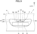
- FIG. 9 is a diagram schematically showing an opening 22K of the lawn mower 2 in the automated lawn mowing system 1 of the third embodiment, together with the peripheral configuration.
- the third embodiment is different from the first embodiment in that the contact surfaces 35A and 36A of both the pair of power receiving terminals 35 and 36 of the lawn mower 2 face downward, and a partition member 31S is provided between the power receiving terminals 35 and 36.
- a partition member 31S is provided between the power receiving terminals 35 and 36.
- the power receiving terminals 35 and 36 are spaced apart along the right-left direction above the plug unit 53 inserted in the recessed portion 2K.
- the structure and support of the power receiving terminals 35 and 36 may be the same as the structure and support of the power receiving terminal 35 of the first embodiment. However, this configuration is not necessarily the case and the power receiving terminals 35 and 36 may be separately disposed in different parts (for example, the vehicle body cover 21 and the vehicle body 11) from among the plurality of parts constituting the lawn mower 2.
- the power receiving terminals 35 and 36 may be shifted in the front-rear direction or the like.
- the plug unit 53 is provided with a plurality (two) of raised portions 58A that are spaced apart along the right-left direction, rising upward and extending in the front-rear direction, and power transmission terminals 55 and 56 are separately provided for the respective raised portions 58A.
- the upper surfaces of the raised portions 58A are inclined surfaces similar to those of the first embodiment so that adhesion of moisture to the power transmission terminals 55 and 56 is prevented. Further, the periphery of the raised portions 58A is also an inclined surface as in the first embodiment so that the water around the raised portions 58A can be quickly discharged from the plug unit 53.
- the partition member 31S is provided between the power receiving terminals 35 and 36, and projects downward from the contact surfaces 35A and 36A of the power receiving terminals 35 and 36.
- the partition member 31S functions as a draining member that actively prevents wet grass and the like from adhering to and straddling between the power receiving terminals 35 and 36, and prevents moisture from adhering to and straddling between the contact surfaces 35A and 36A.
- the shape of the partition member 31S may be changed as appropriate As long as such drainage is achievable.
- the member to which the partition member 31S is attached may be any of the vehicle body cover 21, the vehicle body 11, and the power receiving terminals 35 and 36 as long as the partition member 31S can be disposed in the aforementioned position.
- partition member 31S is preferably a non-conductive member.
- At least the first structure in which the pair of power receiving terminals 35 and 36 are separately disposed in different parts from among the plurality of parts constituting the lawn mower 2, or the second structure in which at least one of the pair of power receiving terminals 35 and 36 has a downward-facing contact surface that comes into contact with the charging station 6 may be used.
- the shape of the plug unit 53 or the like in which the power transmission terminals 55 and 56 are disposed may be changed as appropriate, and widely known structures are also applicable to the shapes and structures of the power transmission terminals 55 and 56 and the power receiving terminals 35 and 36.
- the present invention may be applied to other known lawn mowers and charging stations.
- the present invention is applicable not only to lawn mowers but to various autonomous travel work machines that can move to a charging station by autonomous travel.
- the lawn mower 2 has at least a first structure in which a pair of power receiving terminals 35 and 36 are separately disposed in the vehicle body cover 21 and the vehicle body 11 that are different parts from among a plurality of parts constituting the lawn mower 2, or a second structure in which the power receiving terminal 35, which is one of the pair of power receiving terminals 35 and 36, has a downward-facing contact surface 35A that comes into contact with the charging station 6.
Landscapes
- Engineering & Computer Science (AREA)
- Power Engineering (AREA)
- Transportation (AREA)
- Mechanical Engineering (AREA)
- Aviation & Aerospace Engineering (AREA)
- Radar, Positioning & Navigation (AREA)
- Remote Sensing (AREA)
- Physics & Mathematics (AREA)
- General Physics & Mathematics (AREA)
- Automation & Control Theory (AREA)
- Harvester Elements (AREA)
- Arrangement Or Mounting Of Propulsion Units For Vehicles (AREA)
- Charge And Discharge Circuits For Batteries Or The Like (AREA)
Abstract
Description
- The present invention relates to an autonomous travel work machine and a system.
- An autonomous travel work machine is known, which can travel to a charging station by autonomous travel. As in Japanese Patent No.
6285979 6285979 - Incidentally, when lawn moistened with water or raindrops adheres to a robot lawn mower, electrical continuity may be established between a pair of power receiving terminals through moisture. If the robot lawn mower and the charging station are connected to each other in this state, the pair of terminals provided on the charging station side is energized, which may hinder proper charging. When the terminals on the charging station side are energized, the positive terminals may be corroded due to bimetallic corrosion.
- Therefore, an object of the present invention is to make it possible to suppress the situation in which electrical continuity is established between a pair of power receiving terminals through moisture.
- To achieve the aforementioned object, an autonomous travel work machine capable of traveling to a charging station by autonomous travel includes: a pair of power receiving terminals electrically connected to the charging station. The pair of power receiving terminals have at least a first structure in which the pair of power receiving terminals are separately disposed in different parts from among a plurality of parts constituting the autonomous travel work machine, or a second structure in which at least one of the pair of power receiving terminals has a downward-facing contact surface that comes into contact with the charging station.
- In the aforementioned configuration, a vehicle body that has a traveling function, and a vehicle body cover that covers the vehicle body are included, and in the first structure, the pair of power receiving terminals are separately disposed in the vehicle body and the vehicle body cover.
- Further, in the aforementioned configuration, a recessed portion into which a part of the charging station can enter is included, and at least one of the pair of power receiving terminals is provided in the recessed portion.
- Further, in the aforementioned configuration, in the second structure, the power receiving terminal facing downward is provided in the recessed portion.
- Further, in the aforementioned configuration, in the second structure, the other power receiving terminal has a laterally facing contact surface that comes into contact with the charging station.
- Further, in the aforementioned configuration, in the second structure, the other power receiving terminal is provided below the one power receiving terminal and has an upward-facing contact surface that comes into contact with the charging station, and the part of the charging station is sandwiched between the pair of power receiving terminals from above and below.
- Further, in the aforementioned configuration, in the second structure, the pair of power receiving terminals both have downward-facing contact surfaces that come into contact with the charging station, and a draining partition member is provided between the pair of power receiving terminals.
- Further, in the aforementioned configuration, the pair of power receiving terminals are spaced apart along a direction in which a part of the charging station enters the recessed portion.
- A system includes the autonomous travel work machine and a charging station for the autonomous travel work machine, the charging station includes: a pair of power transmission terminals electrically connected to the pair of power receiving terminals. One of the pair of power transmission terminals has a contact surface that comes into contact with the power receiving terminal, the contact surface facing upward and being an inclined surface that is inclined with respect to the horizontal plane.
- Further, in the aforementioned configuration, a plug unit that has the pair of power transmission terminals spaced apart in the up-down direction and the horizontal direction is included, and the plug unit has an inclined surface in a region between the pair of power transmission terminals, the inclined surface draining water on the region out of the plug unit by utilizing at least gravity.
- According to aspects of the present invention, a situation in which electrical continuity is established between a pair of power receiving terminals through moisture can be suppressed.
-
-
FIG. 1 is a diagram showing the configuration of an automated lawn mowing system according to the first embodiment; -
FIG. 2 is a diagram schematically showing the configuration of a lawn mower; -
FIG. 3 is a diagram showing the state in which the lawn mower and a charging station are electrically connected to each other; -
FIG. 4 is a perspective view of a plug unit; -
FIG. 5 is a diagram showing the plug unit inFIG. 3 together with a part of the lawn mower; -
FIG. 6 is a diagram of a terminal portion viewed from the bottom of the lawn mower; -
FIG. 7 is a diagram schematically showing a sectional side view along a line passing through the central position of the plug unit along the right-left direction inFIG. 3 ; -
FIG. 8 is a diagram schematically showing a sectional side view in the state in which the lawn mower and the plug unit in the automated lawn mowing system of the second embodiment are connected to each other; and -
FIG. 9 is a diagram schematically showing an opening of the lawn mower in the automated lawn mowing system of the third embodiment, together with the peripheral configuration. - Embodiments of the present invention will now be described with reference to the accompanying drawings.
-
FIG. 1 is a diagram showing the configuration of an automated lawn mowing system 1 according to the first embodiment. - The automated lawn mowing system 1 includes a
robot lawn mower 2, anarea wire 5 that defines alawn mowing area 4 that is a work area, and acharging station 6. - The
robot lawn mower 2 is an autonomous travel work machine that mows turf grass while automatically and autonomously running in thelawn mowing area 4 and is an example of an autonomous travel work machine or a self-propelled work machine. In the following description, therobot lawn mower 2 is referred to as "lawn mower 2". - The
area wire 5 is installed so that thelawn mower 2 detects the boundary A of thelawn mowing area 4. Thearea wire 5 is laid along the boundary A and transmits a predetermined signal, and thelawn mower 2 detects the boundary A of thelawn mowing area 4 by detecting the signal from thearea wire 5. - The
charging station 6 is an apparatus that functions as a charging device for charging thelawn mower 2 as well as a standby place where thelawn mower 2 is put on standby when not working. Thelawn mower 2 moves to thecharging station 6 by autonomous travel, for example, at the end of the lawn mowing work, and is charged as appropriate with the electric power supplied from thecharging station 6. Note that thearea wire 5 transmits a predetermined signal based on the electric power or signal supplied from thecharging station 6. -
Fig. 2 is a diagram schematically showing the configuration of alawn mower 2. - The
lawn mower 2 includes avehicle body 11 that has a traveling function and the like, and avehicle body cover 21 that covers thevehicle body 11. Right and leftfront wheels 12 that can be steered to the right and left are provided at the front lower portion of thevehicle body 11, right and leftrear wheels 13 that function as drive wheels are provided at the rear lower portion of thevehicle body 11, and awork unit 14 is provided at the central lower portion of thevehicle body 11. In addition, aterminal portion 31 that is electrically connected to thecharging station 6 is provided at the front portion of thelawn mower 2. The details of theterminal portion 31 will be described later. - The
vehicle body 11 is an electric unit that includes right and left travelingmotors 15 that separately drive the right and leftrear wheels 13, a workunit driving motor 16 that drives thework unit 14, abattery 17 that functions as a power source that supplies operation electric power to each component of thelawn mower 2, awheel speed sensor 18 that detects the rotational speed of the right and leftrear wheels 13 serving as drive wheels, asensor unit 19 that detects thearea wire 5 and the like, and acontrol unit 30 that controls each component of thelawn mower 2. - The
control unit 30 controls the travel of thelawn mower 2 by controlling the driving of the travelingmotor 15 and performs a predetermined operation by controlling the driving of the workunit driving motor 16. Thework unit 14 of this embodiment is a cutting blade disc with a cutting blade, and can perform lawn mowing work when the cutting blade disc is rotated. - The
control unit 30 specifies the position of thelawn mower 2 based on the results of detection by thewheel speed sensor 18 and thesensor unit 19, and controls the travel of thelawn mower 2 based on the specified position. Hence, it can travel so that the lawn in thelawn mowing area 4 may be appropriately mowed, and can move to thecharging station 6 after completion of the lawn mowing work. - The configuration of a well-known robot lawn mower can be widely applied to the configuration of the
vehicle body 11 except theterminal portion 31. For example, technology using a position detection device, such as GPS or a gyro sensor, or image recognition technology using a camera, or other technology may be used as technology for specifying thelawn mowing area 4, thecharging station 6, the current position, and the like. - The
vehicle body cover 21 includes amain cover 22 that covers at least the front portion of thevehicle body 11, and atop cover 23 that is coupled to themain cover 22 from above. Themain cover 22 is formed as a cover that covers the front, rear, left, and right sides of thevehicle body 11 and opens a part of thevehicle body 11 upward, and is made of a resin material. Thetop cover 23 is formed as a cover that covers a portion where a part of thevehicle body 11 in themain cover 22 is opened, and is made of a resin material. These covers 22 and 23 function as a protective cover for preventing rainwater and dust from adhering to thevehicle body 11 and a decorative cover for improving the appearance. - Note that the material for the
body cover 21 is not limited to resin. In the case where thelawn mower 2 is compact, themain cover 22 and thetop cover 23 may be integrally formed. -
Fig. 3 is a diagram showing the state in which thelawn mower 2 and acharging station 6 are electrically connected to each other. For convenience of explanation, thevehicle body cover 21 is indicated by the two-dot chain line inFIG. 3 . - As shown in
FIG. 3 , the chargingstation 6 includes aconnection base 51 to which thelawn mower 2 is connected, and a mountingbase 52 on which thelawn mower 2 connected to theconnection base 51 is mounted. Theconnection base 51 has aplug unit 53 that protrudes toward thelawn mower 2 on the mountingbase 52. - Here,
FIG. 4 is a perspective view of theplug unit 53. Theplug unit 53 is formed in a triangular shape that narrows toward the rear in a top view, and includes a pair ofpower transmission terminals power transmission terminals power transmission terminal 55 is formed as a terminal that protrudes upward from the center of theplug unit 53 when viewed along the right-left direction and the intermediate position of theplug unit 53 when viewed along the front-rear direction. The negative-sidepower transmission terminal 56 is a plate-like terminal that protrudes, when viewed along the right-left direction, outward from one of the right and left surfaces of the plug unit 53 (in this embodiment, the surface on the left side of the lawn mower 2) and the tip side of theplug unit 53. - To be specific, the
plug unit 53 is integrally provided with abasal section 57 connected to theconnection base 51 and aunit body 58 having a triangular shape in a top view and extending from thebasal section 57. Theunit body 58 has a raisedportion 58A that rises upward from the central portion when viewed along the right-left direction and that extends in the front-rear direction, and the upper surface of the raisedportion 58A is inclined obliquely downward from thebasal section 57 toward the tip of theunit body 58. The positive-sidepower transmission terminal 55 is disposed in a region corresponding to the raisedportion 58A, with a part thereof protruding upward. For this reason, even if moisture such as rainwater adheres to the raisedportion 58A, moisture can gravitationally flow out of the raisedportion 58A, and rainwater does not remain around the positive-sidepower transmission terminal 55. - Further, the raised
portion 58A has an opening 58B that opens upward on the tip side of the positive-sidepower transmission terminal 55, and this opening 58B allows moisture flowing along the slope of the raisedportion 58A to quickly drop downward. - Also in the
upper surfaces portion 58A, theunit body 58 is inclined obliquely downward from thebasal section 57 toward the tip of theunit body 58. For this reason, even if moisture such as rainwater adheres to the right and leftupper surfaces unit body 58. - Since the negative-side
power transmission terminal 56 is provided on the side surface of theunit body 58, even if moisture such as rainwater adheres thereto, it can quickly drop gravitationally. - Further, as shown in
FIG. 4 , the positive-sidepower transmission terminal 55 and the negative-sidepower transmission terminal 56 are spaced apart in the up-down direction, the front-rear direction, and the right-left direction. This facilitates avoidance of establishment of electrical continuity between the positive-sidepower transmission terminal 55 and the negative-sidepower transmission terminal 56 by moisture such as rainwater. Even if the grass that is attached to thelawn mower 2 and wetted with water adheres to theplug unit 53, the situation where establishment of electrical continuity between the positive-sidepower transmission terminal 55 and the negative-sidepower transmission terminal 56 by the wet grass is avoided easily. -
FIG. 5 is a diagram showing theplug unit 53 inFIG. 3 together with a part of thelawn mower 2. As shown inFIG. 5 , anopening 22K that allows theplug unit 53 to be inserted toward theterminal portion 31 is provided in the front surface of themain cover 22 of thelawn mower 2. Further, aspace 31K into which theplug unit 53 can be inserted is provided between the opening 22K and theterminal portion 31. Theopening 22K and thespace 31K define a recessedportion 2K that allows theplug unit 53, which is a part of the chargingstation 6, to be inserted into theterminal portion 31. -
FIG. 6 is a diagram of aterminal portion 31 viewed from the bottom of thelawn mower 2. For convenience of explanation, inFIG. 6 , theplug unit 53 inserted to the bottom of the recessedportion 2K is indicated by the two-dot chain line.FIG. 7 is a diagram schematically showing a sectional side view along a line passing through the central position of theplug unit 53 along the right-left direction inFIG. 3 . - As shown in
FIGS. 5 to 7 , theterminal portion 31 has the positive-sidepower receiving terminal 35 provided on thevehicle body cover 21, the negative-sidepower receiving terminal 36 provided on thevehicle body 11, and adummy terminal 37 opposed to the negative-sidepower receiving terminal 36. - The positive-side
power receiving terminal 35 is attached to the foremost portion of themain cover 22 and is formed of a metal plate with a downward-facingcontact surface 35A (seeFIG. 7 ) which is in contact with the positive-sidepower transmission terminal 55 of theplug unit 53. To be specific, the positive-sidepower receiving terminal 35 is fixed to the rear surface of the foremost portion of themain cover 22 with a fastening member 38 (seeFIG. 5 ) inserted from the front of themain cover 22, and protrudes downward from the foremost portion of themain cover 22 toward the recessedportion 2K. As shown inFIG. 7 , the positive-sidepower receiving terminal 35 is formed so that it has a U-shaped cross section that opens upward and its lower surface is thecontact surface 35A that comes in contact with the upper surface of the positive-sidepower transmission terminal 55 of theplug unit 53 inserted in the recessedportion 2K. - As shown in
FIG. 7 , the upper surface of the positive-sidepower transmission terminal 55 of theplug unit 53, that is, the contact surface comes in contact with the positive-sidepower receiving terminal 35 is inclined downward and toward the lawn mower 2 (the bottom of the recessedportion 2K). For this reason, even if moisture such as rainwater adheres to the upper surface of the positive-sidepower transmission terminal 55, moisture can quickly flow out of the terminal 55 gravitationally, which facilitates avoidance of the phenomenon in which rainwater remains on the upper surface of the positive-sidepower transmission terminal 55. - By the way, wet grass or raindrops may enter the recessed
portion 2K of thelawn mower 2. In terms of this, in this configuration, the positive-sidepower receiving terminal 35 of thelawn mower 2 faces downward, so that wet grass or raindrops are unlikely to adhere thereto and, and even if it adheres thereto, it easily drops by gravity compared to the case where the positive-sidepower receiving terminal 35 faces upward. - Besides, the positive-side
power transmission terminal 55 that comes in contact with the positive-sidepower receiving terminal 35 is an upward inclined surface that is inclined with respect to the horizontal plane, which facilitates avoidance of the remaining moisture as described above. Further, theterminals terminals terminals - Further, as shown in
FIGS. 6 and7 , the negative-sidepower receiving terminal 36 is spaced apart from the positive-sidepower receiving terminal 35 in the font-rear direction and the right-left direction. The negative-sidepower receiving terminal 36 is attached to afront projecting portion 11T (seeFIG. 6 ) that constitutes a part of the foremost portion of thevehicle body 11, and is, in the bottom view shown inFIG. 6 , a metal plate that curves in a U-shape from one of the right and left sides (in this embodiment, the right side inFIG. 6 ) to the other one of the right and left sides (the left side inFIG. 6 ). In other words, the negative-sidepower receiving terminal 36 is disposed in a position shifted to one of the right and left sides from the center plane M1 of thevehicle body 11 when viewed along the right and left direction (coinciding with the center plane of thelawn mower 2 when viewed along the right and left direction), and has a laterally (leftward inFIG. 6 ) facing contact surface that comes in contact with the negative-sidepower transmission terminal 56. - To be specific, the negative-side
power receiving terminal 36 is provided in the position that overlaps with the negative-sidepower transmission terminal 56 of theplug unit 53 when theplug unit 53 is inserted to the position indicated by the two-dot chain line shown inFIG. 6 . The negative-sidepower receiving terminal 36 curves in a U shape and deforms so that the pressure of contact with the negative-sidepower transmission terminal 56 does not become excessive, thereby keeping an appropriate state of contact between theterminals power transmission terminal 56 side may be made deformable. - As shown in
FIG. 6 , thedummy terminal 37 facing the negative-sidepower receiving terminal 36 and the structure supporting thedummy terminal 37 are formed symmetrically to the negative-sidepower receiving terminal 36 and its peripheral structure, respectively. To be specific, thedummy terminal 37 and its support structure are formed in positions and structures that are symmetric with respect to the center plane M1 of thevehicle body 11 when viewed along the right-left direction. Since theplug unit 53 is inserted between thedummy terminal 37 and the negative-sidepower receiving terminal 36, it is easy to guide the travel direction of thelawn mower 2 toward theplug unit 53 to an appropriate direction or keep an appropriate state of the contact between the negative-sidepower receiving terminal 36 and the negative-sidepower transmission terminal 56. - In addition, the
terminal portion 31 is provided with acontact portion 39 that the tip of theplug unit 53 comes in contact with. Thecontact portion 39 is provided in the position that theplug unit 53 comes in contact with when the pair ofpower receiving terminals terminal portion 31 and the pair ofpower transmission terminals plug unit 53 are electrically connected to each other. - In this configuration, the negative-side
power receiving terminal 36 of theterminal portion 31 is provided on the relatively bottom side in the recessedportion 2K, so that wet grass or raindrops are unlikely to adhere to the negative-sidepower receiving terminal 36. Besides, the negative-sidepower receiving terminal 36 and the positive-sidepower receiving terminal 35 are separately disposed in thevehicle body cover 21 and thevehicle body 11, so that the continuity route (represented by X inFIG. 7 ) straddling between thevehicle body cover 21 and thevehicle body 11 can be made long, and the movement of moisture at the boundary between thevehicle body cover 21 and thevehicle body 11 can be suppressed easily. - Even if wet grass or moisture adheres to the negative-side
power receiving terminal 36, since the negative-sidepower receiving terminal 36 and the negative-sidepower transmission terminal 56 rub against each other, wiping action for removing foreign matters such as moisture from the contact surfaces of theterminals power receiving terminal 36 nevertheless, since the positive-sidepower receiving terminal 35 is spaced apart along the front-rear direction from and is located at a different height from the negative-sidepower receiving terminal 36, the situation where electrical continuity is established between the pair ofpower receiving terminals - Through these facts, the situation where electrical continuity is established between the pair of
power receiving terminals power transmission terminals - As described above, the
lawn mower 2 of this embodiment has a first structure in which the pair ofpower receiving terminals vehicle body cover 21 and thevehicle body 11 which are different parts from among the plurality of parts constituting thelawn mower 2. With this first structure, the continuity route X (seeFIG. 7 ) can be made long, the movement of moisture at the boundary between parts can be easily canceled, and the situation where electrical continuity is established between the pair ofpower receiving terminals power transmission terminals - Note that the pair of
power receiving terminals vehicle body cover 21 and thevehicle body 11, and may be separately disposed in a plurality of other different parts constituting thelawn mower 2. - The
lawn mower 2 also has a second structure in which thepower receiving terminal 35, which is one of the pair ofpower receiving terminals contact surface 35A (seeFIG. 7 ) which comes in contact with the chargingstation 6 and faces downward. With this second structure, moisture and the like is unlikely to remain in thepower receiving terminal 35 facing downward, which also suppresses the situation where electrical continuity is established between the pair ofpower receiving terminals - Note that, instead of the
power receiving terminal 35 or in addition to thepower receiving terminal 35, the other one, that is, thepower receiving terminal 36 may have a downward-facing contact surface that comes in contact with the chargingstation 6. In short, when at least one of the pair ofpower receiving terminals station 6, the situation where electrical continuity is established between the pair ofpower receiving terminals - Further, the
lawn mower 2 has a recessedportion 2K into which theplug unit 53 that is a part of the chargingstation 6 can enter, and the pair ofpower receiving terminals portion 2K, which also makes it difficult for moisture such as rainwater to adhere to thepower receiving terminals power receiving terminals power receiving terminals portion 2K, the situation where electrical continuity is established between thepower receiving terminals - In addition, since the
power receiving terminal 35 facing downward in the second structure is provided in the recessedportion 2K, moisture is more unlikely to adhere to thepower receiving terminal 35. Besides, since the other terminal, that is, thepower receiving terminal 36 in the second structure has a laterally facing contact surface that comes in contact with the chargingstation 6, it is also difficult for moisture to adhere to or remain on the other terminal, that is, thepower receiving terminal 36. - Furthermore, since one of the pair of
power transmission terminals station 6 has a contact surface that comes into contact with thepower receiving terminal 36 so that the contact surface faces upward and is inclined with respect to the horizontal plane, even moisture or the like on the contact surface can be discharged quickly. The wiping action between theterminals terminals - The charging
station 6 further includes aplug unit 53 provided with a pair ofpower transmission terminals plug unit 53 has an inclined surface in a region between the pair ofpower transmission terminals plug unit 53 by utilizing at least gravity. Hence, it is possible to suppress the situation where moisture or the like remains on thepower transmission terminals -
FIG. 8 is a diagram schematically showing a sectional side view in the state in which thelawn mower 2 and theplug unit 53 in the automated lawn mowing system 1 of the second embodiment are connected to each other. - In the second embodiment, the
power receiving terminal 36 of thelawn mower 2 and thepower transmission terminal 56 of the chargingstation 6 are different from those in the first embodiment. Hereinafter, the description overlapping with the first embodiment will be omitted, and differences will be explained. - The
power receiving terminal 36 of thelawn mower 2 is provided in a position shifted downward and rearward from thepower receiving terminal 35 facing downward. Thepower receiving terminal 36 is formed so that it has a U-shaped cross section that opens downward and its upper surface is thecontact surface 36A that comes into contact with the lower surface of the positive-sidepower transmission terminal 56 of theplug unit 53 inserted in the recessedportion 2K. - The
power transmission terminal 56 of the chargingstation 6 is provided on the lower surface of theplug unit 53. Thepower transmission terminal 56 projects downward from the lower surface of theplug unit 53, and the lower surface is an inclined surface inclined obliquely upward and toward thelawn mower 2. - In the second embodiment, the
power receiving terminal 36 of thelawn mower 2 is provided below thepower receiving terminal 35 facing downward, and thecontact surface 36A that comes into electrical contact with the chargingstation 6 faces upward, and theplug unit 53 constituting a part of the chargingstation 6 is sandwiched between the pair ofpower receiving terminals - With this configuration, the
plug unit 53 enters between the upper andlower terminals terminals power receiving terminals power transmission terminals 55 and 56) through moisture. Moreover, it is easy to use parts of onepower receiving terminal 35 also in the otherpower receiving terminal 36. - Further, moisture or the like is unlikely to adhere to the
power receiving terminal 36 facing upward because it is disposed near the bottom of the recessedportion 2K. Since thepower transmission terminal 56 that comes into contact with thepower receiving terminal 36 faces downward, moisture or the like is less likely to adhere to thepower transmission terminal 56. This effectively suppresses the situation where electrical continuity is established between the pair ofpower transmission terminals -
FIG. 9 is a diagram schematically showing anopening 22K of thelawn mower 2 in the automated lawn mowing system 1 of the third embodiment, together with the peripheral configuration. - The third embodiment is different from the first embodiment in that the contact surfaces 35A and 36A of both the pair of
power receiving terminals lawn mower 2 face downward, and apartition member 31S is provided between thepower receiving terminals - As shown in
FIG. 9 , thepower receiving terminals plug unit 53 inserted in the recessedportion 2K. The structure and support of thepower receiving terminals power receiving terminal 35 of the first embodiment. However, this configuration is not necessarily the case and thepower receiving terminals vehicle body cover 21 and the vehicle body 11) from among the plurality of parts constituting thelawn mower 2. Thepower receiving terminals - The
plug unit 53 is provided with a plurality (two) of raisedportions 58A that are spaced apart along the right-left direction, rising upward and extending in the front-rear direction, andpower transmission terminals portions 58A. The upper surfaces of the raisedportions 58A are inclined surfaces similar to those of the first embodiment so that adhesion of moisture to thepower transmission terminals portions 58A is also an inclined surface as in the first embodiment so that the water around the raisedportions 58A can be quickly discharged from theplug unit 53. - The
partition member 31S is provided between thepower receiving terminals power receiving terminals partition member 31S functions as a draining member that actively prevents wet grass and the like from adhering to and straddling between thepower receiving terminals partition member 31S may be changed as appropriate As long as such drainage is achievable. In addition, the member to which thepartition member 31S is attached may be any of thevehicle body cover 21, thevehicle body 11, and thepower receiving terminals partition member 31S can be disposed in the aforementioned position. - Note that the
partition member 31S is preferably a non-conductive member. - According to the third embodiment, the contact surfaces 35A and 36A, which come into contact with the charging
station 6, of both of the pair ofpower receiving terminals partition member 31S lies between thepower receiving terminals power receiving terminals power receiving terminals power receiving terminals power transmission terminals - Each of the above-described embodiments is merely one embodiment of the present invention, and any modification and application can be made without departing from the scope of the present invention.
- For example, in each of the above-described embodiments, at least the first structure in which the pair of
power receiving terminals lawn mower 2, or the second structure in which at least one of the pair ofpower receiving terminals station 6 may be used. Moreover, the shape of theplug unit 53 or the like in which thepower transmission terminals power transmission terminals power receiving terminals - Although the case where the present invention is applied to the
lawn mower 2 and the chargingstation 6 shown inFIG. 1 and other drawings has been described, the present invention may be applied to other known lawn mowers and charging stations. Moreover, the present invention is applicable not only to lawn mowers but to various autonomous travel work machines that can move to a charging station by autonomous travel. - An object is to suppress the situation in which electrical continuity is established between a pair of power receiving terminals through moisture. The
lawn mower 2 has at least a first structure in which a pair ofpower receiving terminals vehicle body cover 21 and thevehicle body 11 that are different parts from among a plurality of parts constituting thelawn mower 2, or a second structure in which thepower receiving terminal 35, which is one of the pair ofpower receiving terminals contact surface 35A that comes into contact with the chargingstation 6. -
- 1
- Automated lawn mowing system
- 2
- Robot lawn mower (autonomous travel work machine)
- 2K
- Recessed portion
- 4
- Lawn mowing area
- 5
- Area wire
- 6
- Charging station
- 11
- Vehicle body
- 12
- Front wheel
- 13
- Rear wheel
- 14
- Work unit
- 21
- Vehicle body cover
- 22
- Main cover
- 22K
- Opening
- 23
- Top cover
- 31
- Terminal portion
- 31K
- Space
- 31S
- Partition member
- 35
- Positive-side power receiving terminal
- 36
- Negative-side power receiving terminal
- 37
- Dummy terminal
- 51
- Connection base
- 52
- Mounting base
- 53
- Plug unit
- 55
- Positive-side power transmission terminal
- 56
- Negative-side power transmission terminal
- 58
- Unit body
- 58A
- Raised portion
Claims (10)
- An autonomous travel work machine capable of traveling to a charging station (6) by autonomous travel, the autonomous travel work machine characterized by comprising:a pair of power receiving terminals (35, 36) electrically connected to the charging station, whereinthe pair of power receiving terminals have at least a first structure in which the pair of power receiving terminals are separately disposed in different parts from among a plurality of parts constituting the autonomous travel work machine, or a second structure in which at least one of the pair of power receiving terminals has a downward-facing contact surface that comes into contact with the charging station.
- The autonomous travel work machine according to Claim 1, comprising:a vehicle body (11) that has a traveling function, and a vehicle body cover (21) that covers the vehicle body, whereinin the first structure, the pair of power receiving terminals are separately disposed in the vehicle body and the vehicle body cover.
- The autonomous travel work machine according to Claim 1 or 2, comprising:a recessed portion (2K) into which a part of the charging station can enter, whereinat least one of the pair of power receiving terminals is provided in the recessed portion.
- The autonomous travel work machine according to Claim 3, wherein in the second structure, the power receiving terminal facing downward is provided in the recessed portion.
- The autonomous travel work machine according to any one of Claims 1 to 4, wherein in the second structure, the other power receiving terminal has a laterally facing contact surface that comes into contact with the charging station.
- The autonomous travel work machine according to any one of Claims 1 to 4, wherein in the second structure, the other power receiving terminal is provided below one power receiving terminal and has an upward-facing contact surface that comes into contact with the charging station, and a part of the charging station is sandwiched between the pair of power receiving terminals from above and below.
- The autonomous travel work machine according to any one of Claims 1 to 4, wherein in the second structure, the pair of power receiving terminals both have downward-facing contact surfaces that come into contact with the charging station, and a draining partition member (31S) is provided between the pair of power receiving terminals.
- The autonomous travel work machine according to Claim 3 or 4, wherein the pair of power receiving terminals are spaced apart along a direction in which the part of the charging station enters the recessed portion.
- A system comprising the autonomous travel work machine (2) according to Claim 1 and a charging station (6) for the autonomous travel work machine, the charging station characterized by comprising:a pair of power transmission terminals (55, 56) electrically connected to the pair of power receiving terminals, whereinone of the pair of power transmission terminals has a contact surface that comes into contact with the power receiving terminal, the contact surface facing upward and being an inclined surface that is inclined with respect to the horizontal plane.
- The system according to Claim 9, wherein the charging station comprises a plug unit (53) that has the pair of power transmission terminals spaced apart in the up-down direction and the horizontal direction, and
the plug unit has an inclined surface in a region between the pair of power transmission terminals, the inclined surface draining water on the region out of the plug unit by utilizing at least gravity.
Applications Claiming Priority (1)
| Application Number | Priority Date | Filing Date | Title |
|---|---|---|---|
| JP2019062742A JP2020162397A (en) | 2019-03-28 | 2019-03-28 | Autonomous driving machine and charging station |
Publications (2)
| Publication Number | Publication Date |
|---|---|
| EP3715170A1 true EP3715170A1 (en) | 2020-09-30 |
| EP3715170B1 EP3715170B1 (en) | 2023-03-08 |
Family
ID=69845047
Family Applications (1)
| Application Number | Title | Priority Date | Filing Date |
|---|---|---|---|
| EP20158967.8A Active EP3715170B1 (en) | 2019-03-28 | 2020-02-24 | Autonomous driving work machine and system |
Country Status (3)
| Country | Link |
|---|---|
| US (1) | US11260765B2 (en) |
| EP (1) | EP3715170B1 (en) |
| JP (1) | JP2020162397A (en) |
Families Citing this family (9)
| Publication number | Priority date | Publication date | Assignee | Title |
|---|---|---|---|---|
| US11219165B1 (en) * | 2019-10-09 | 2022-01-11 | Vinergy, Inc. | Motorized cart for transporting agricultural harvest containers |
| US12296694B2 (en) | 2021-03-10 | 2025-05-13 | Techtronic Cordless Gp | Lawnmowers |
| US12443180B2 (en) | 2021-11-10 | 2025-10-14 | Techtronic Cordless Gp | Robotic lawn mowers |
| AU2023200381A1 (en) | 2022-01-31 | 2023-08-17 | Techtronic Cordless Gp | Robotic garden tool |
| EP4270138A1 (en) | 2022-04-28 | 2023-11-01 | Techtronic Cordless GP | Creation of a virtual boundary for a robotic garden tool |
| US12472611B2 (en) | 2022-05-31 | 2025-11-18 | Techtronic Cordless Gp | Peg driver |
| CN114846993B (en) * | 2022-06-13 | 2024-02-23 | 美智纵横科技有限责任公司 | Lawn mowing robots and lawn mowing equipment |
| EP4310621B1 (en) | 2022-07-19 | 2025-02-12 | Techtronic Cordless GP | Display for controlling robotic tool |
| AU2023206123A1 (en) | 2022-07-29 | 2024-02-15 | Techtronic Cordless Gp | Generation of a cryptography key for a robotic garden tool |
Citations (4)
| Publication number | Priority date | Publication date | Assignee | Title |
|---|---|---|---|---|
| EP2717109A1 (en) * | 2012-10-04 | 2014-04-09 | Viking GmbH | Loading device for a self-propelled work device |
| JP6285979B2 (en) | 2016-03-31 | 2018-02-28 | 本田技研工業株式会社 | Charging station and charging station guidance device for autonomous vehicle |
| US20180188737A1 (en) * | 2016-12-30 | 2018-07-05 | Lg Electronics Inc. | Robot cleaner system having charging station |
| CN108990508A (en) * | 2018-08-02 | 2018-12-14 | 苏州科瓴精密机械科技有限公司 | Intelligent robot system |
Family Cites Families (11)
| Publication number | Priority date | Publication date | Assignee | Title |
|---|---|---|---|---|
| US8212533B2 (en) * | 2009-12-23 | 2012-07-03 | Toyota Motor Engineering & Manufacturing North America, Inc. | Robot battery charging apparatuses and methods |
| DE102014226357A1 (en) * | 2014-12-18 | 2016-06-23 | Robert Bosch Gmbh | Charging station and method for automatically charging an electrical energy store in a vehicle |
| DE102014226755A1 (en) * | 2014-12-22 | 2016-06-23 | Robert Bosch Gmbh | Device and method for electrically connecting a charging station with a charging socket of a vehicle |
| US10383499B2 (en) * | 2017-08-31 | 2019-08-20 | Irobot Corporation | Wet robot docking station |
| US11586198B2 (en) * | 2017-09-04 | 2023-02-21 | Kawasaki Jukogyo Kabushiki Kaisha | Charging system for autonomous underwater vehicle and method of lifting and recovering autonomous underwater vehicle |
| US11219347B2 (en) * | 2017-12-22 | 2022-01-11 | Bissell Inc. | Robotic cleaner |
| EP3549423B1 (en) * | 2018-04-06 | 2021-06-16 | Lg Electronics Inc. | Lawn mower robot |
| EP3549424B1 (en) * | 2018-04-06 | 2022-01-05 | Lg Electronics Inc. | Lawn mower robot |
| JP2020156446A (en) * | 2019-03-28 | 2020-10-01 | 本田技研工業株式会社 | Lawn mower |
| JP2021027810A (en) * | 2019-08-09 | 2021-02-25 | 本田技研工業株式会社 | Work machine |
| US11605961B2 (en) * | 2019-09-13 | 2023-03-14 | Echo Incorporated | System for facilitating the charging of a battery-operated apparatus |
-
2019
- 2019-03-28 JP JP2019062742A patent/JP2020162397A/en active Pending
-
2020
- 2020-02-21 US US16/797,241 patent/US11260765B2/en active Active
- 2020-02-24 EP EP20158967.8A patent/EP3715170B1/en active Active
Patent Citations (4)
| Publication number | Priority date | Publication date | Assignee | Title |
|---|---|---|---|---|
| EP2717109A1 (en) * | 2012-10-04 | 2014-04-09 | Viking GmbH | Loading device for a self-propelled work device |
| JP6285979B2 (en) | 2016-03-31 | 2018-02-28 | 本田技研工業株式会社 | Charging station and charging station guidance device for autonomous vehicle |
| US20180188737A1 (en) * | 2016-12-30 | 2018-07-05 | Lg Electronics Inc. | Robot cleaner system having charging station |
| CN108990508A (en) * | 2018-08-02 | 2018-12-14 | 苏州科瓴精密机械科技有限公司 | Intelligent robot system |
Also Published As
| Publication number | Publication date |
|---|---|
| EP3715170B1 (en) | 2023-03-08 |
| US11260765B2 (en) | 2022-03-01 |
| US20200307397A1 (en) | 2020-10-01 |
| JP2020162397A (en) | 2020-10-01 |
Similar Documents
| Publication | Publication Date | Title |
|---|---|---|
| EP3715170B1 (en) | Autonomous driving work machine and system | |
| US12054062B2 (en) | Robotic work tool system and a charging connector arrangement for a robotic work tool system | |
| EP3073602B1 (en) | Charging station for autonomously navigating utility vehicle | |
| EP2626761B1 (en) | Control apparatus for unmanned autonomous vehicle operating in an arrangement of area wire | |
| EP3056959B1 (en) | Control apparatus for autonomously navigating utility vehicle | |
| US11612914B2 (en) | Cleaning system and method of controlling cleaning system | |
| JP2017176117A (en) | Control device for autonomous vehicle | |
| CN112799390B (en) | Self-moving equipment and working method thereof | |
| JP2016208886A (en) | Grass mower | |
| US12268120B2 (en) | Autonomous travel working machine and charging station | |
| JP2016028906A (en) | Autonomous travel vehicle | |
| EP4060449B1 (en) | Work robot | |
| JP2016208885A (en) | Self-propelled mower | |
| DE112019007848T5 (en) | STATION AND POWER SUPPLY DEVICE OF AN AUTONOMOUSLY PROCEEDING WORK MACHINE | |
| US20160052575A1 (en) | Utility vehicle | |
| CN220986682U (en) | Automatic working system | |
| WO2017204718A1 (en) | A wheeled motor vehicle and a method for controlling the flow of electric power of an electric system of such a vehicle | |
| US11844304B2 (en) | Autonomous travel work machine | |
| JP7333582B2 (en) | Unmanned work equipment | |
| CN220369057U (en) | Autonomous mowing robot | |
| US20250113770A1 (en) | Working robot | |
| CN209776610U (en) | Automatic guiding vehicle | |
| CN117501959A (en) | A lawn mower robot wiring structure and smart lawn mower | |
| JPH0974818A (en) | Mow mark boundary detection device | |
| JP2020027428A (en) | Charging device for work machine |
Legal Events
| Date | Code | Title | Description |
|---|---|---|---|
| PUAI | Public reference made under article 153(3) epc to a published international application that has entered the european phase |
Free format text: ORIGINAL CODE: 0009012 |
|
| STAA | Information on the status of an ep patent application or granted ep patent |
Free format text: STATUS: REQUEST FOR EXAMINATION WAS MADE |
|
| 17P | Request for examination filed |
Effective date: 20200224 |
|
| AK | Designated contracting states |
Kind code of ref document: A1 Designated state(s): AL AT BE BG CH CY CZ DE DK EE ES FI FR GB GR HR HU IE IS IT LI LT LU LV MC MK MT NL NO PL PT RO RS SE SI SK SM TR |
|
| AX | Request for extension of the european patent |
Extension state: BA ME |
|
| STAA | Information on the status of an ep patent application or granted ep patent |
Free format text: STATUS: EXAMINATION IS IN PROGRESS |
|
| 17Q | First examination report despatched |
Effective date: 20220405 |
|
| REG | Reference to a national code |
Ref country code: DE Ref legal event code: R079 Ref document number: 602020008611 Country of ref document: DE Free format text: PREVIOUS MAIN CLASS: B60L0053360000 Ipc: B60L0053160000 |
|
| GRAP | Despatch of communication of intention to grant a patent |
Free format text: ORIGINAL CODE: EPIDOSNIGR1 |
|
| STAA | Information on the status of an ep patent application or granted ep patent |
Free format text: STATUS: GRANT OF PATENT IS INTENDED |
|
| RIC1 | Information provided on ipc code assigned before grant |
Ipc: B60L 53/36 20190101ALI20220928BHEP Ipc: B60L 53/16 20190101AFI20220928BHEP |
|
| INTG | Intention to grant announced |
Effective date: 20221031 |
|
| GRAS | Grant fee paid |
Free format text: ORIGINAL CODE: EPIDOSNIGR3 |
|
| GRAA | (expected) grant |
Free format text: ORIGINAL CODE: 0009210 |
|
| STAA | Information on the status of an ep patent application or granted ep patent |
Free format text: STATUS: THE PATENT HAS BEEN GRANTED |
|
| AK | Designated contracting states |
Kind code of ref document: B1 Designated state(s): AL AT BE BG CH CY CZ DE DK EE ES FI FR GB GR HR HU IE IS IT LI LT LU LV MC MK MT NL NO PL PT RO RS SE SI SK SM TR |
|
| REG | Reference to a national code |
Ref country code: CH Ref legal event code: EP Ref country code: AT Ref legal event code: REF Ref document number: 1552376 Country of ref document: AT Kind code of ref document: T Effective date: 20230315 |
|
| REG | Reference to a national code |
Ref country code: DE Ref legal event code: R096 Ref document number: 602020008611 Country of ref document: DE |
|
| REG | Reference to a national code |
Ref country code: IE Ref legal event code: FG4D |
|
| REG | Reference to a national code |
Ref country code: LT Ref legal event code: MG9D |
|
| REG | Reference to a national code |
Ref country code: NL Ref legal event code: MP Effective date: 20230308 |
|
| PG25 | Lapsed in a contracting state [announced via postgrant information from national office to epo] |
Ref country code: RS Free format text: LAPSE BECAUSE OF FAILURE TO SUBMIT A TRANSLATION OF THE DESCRIPTION OR TO PAY THE FEE WITHIN THE PRESCRIBED TIME-LIMIT Effective date: 20230308 Ref country code: NO Free format text: LAPSE BECAUSE OF FAILURE TO SUBMIT A TRANSLATION OF THE DESCRIPTION OR TO PAY THE FEE WITHIN THE PRESCRIBED TIME-LIMIT Effective date: 20230608 Ref country code: LV Free format text: LAPSE BECAUSE OF FAILURE TO SUBMIT A TRANSLATION OF THE DESCRIPTION OR TO PAY THE FEE WITHIN THE PRESCRIBED TIME-LIMIT Effective date: 20230308 Ref country code: LT Free format text: LAPSE BECAUSE OF FAILURE TO SUBMIT A TRANSLATION OF THE DESCRIPTION OR TO PAY THE FEE WITHIN THE PRESCRIBED TIME-LIMIT Effective date: 20230308 Ref country code: HR Free format text: LAPSE BECAUSE OF FAILURE TO SUBMIT A TRANSLATION OF THE DESCRIPTION OR TO PAY THE FEE WITHIN THE PRESCRIBED TIME-LIMIT Effective date: 20230308 Ref country code: ES Free format text: LAPSE BECAUSE OF FAILURE TO SUBMIT A TRANSLATION OF THE DESCRIPTION OR TO PAY THE FEE WITHIN THE PRESCRIBED TIME-LIMIT Effective date: 20230308 |
|
| REG | Reference to a national code |
Ref country code: AT Ref legal event code: MK05 Ref document number: 1552376 Country of ref document: AT Kind code of ref document: T Effective date: 20230308 |
|
| PG25 | Lapsed in a contracting state [announced via postgrant information from national office to epo] |
Ref country code: SE Free format text: LAPSE BECAUSE OF FAILURE TO SUBMIT A TRANSLATION OF THE DESCRIPTION OR TO PAY THE FEE WITHIN THE PRESCRIBED TIME-LIMIT Effective date: 20230308 Ref country code: NL Free format text: LAPSE BECAUSE OF FAILURE TO SUBMIT A TRANSLATION OF THE DESCRIPTION OR TO PAY THE FEE WITHIN THE PRESCRIBED TIME-LIMIT Effective date: 20230308 Ref country code: GR Free format text: LAPSE BECAUSE OF FAILURE TO SUBMIT A TRANSLATION OF THE DESCRIPTION OR TO PAY THE FEE WITHIN THE PRESCRIBED TIME-LIMIT Effective date: 20230609 Ref country code: FI Free format text: LAPSE BECAUSE OF FAILURE TO SUBMIT A TRANSLATION OF THE DESCRIPTION OR TO PAY THE FEE WITHIN THE PRESCRIBED TIME-LIMIT Effective date: 20230308 |
|
| PG25 | Lapsed in a contracting state [announced via postgrant information from national office to epo] |
Ref country code: SM Free format text: LAPSE BECAUSE OF FAILURE TO SUBMIT A TRANSLATION OF THE DESCRIPTION OR TO PAY THE FEE WITHIN THE PRESCRIBED TIME-LIMIT Effective date: 20230308 Ref country code: RO Free format text: LAPSE BECAUSE OF FAILURE TO SUBMIT A TRANSLATION OF THE DESCRIPTION OR TO PAY THE FEE WITHIN THE PRESCRIBED TIME-LIMIT Effective date: 20230308 Ref country code: PT Free format text: LAPSE BECAUSE OF FAILURE TO SUBMIT A TRANSLATION OF THE DESCRIPTION OR TO PAY THE FEE WITHIN THE PRESCRIBED TIME-LIMIT Effective date: 20230710 Ref country code: EE Free format text: LAPSE BECAUSE OF FAILURE TO SUBMIT A TRANSLATION OF THE DESCRIPTION OR TO PAY THE FEE WITHIN THE PRESCRIBED TIME-LIMIT Effective date: 20230308 Ref country code: CZ Free format text: LAPSE BECAUSE OF FAILURE TO SUBMIT A TRANSLATION OF THE DESCRIPTION OR TO PAY THE FEE WITHIN THE PRESCRIBED TIME-LIMIT Effective date: 20230308 Ref country code: AT Free format text: LAPSE BECAUSE OF FAILURE TO SUBMIT A TRANSLATION OF THE DESCRIPTION OR TO PAY THE FEE WITHIN THE PRESCRIBED TIME-LIMIT Effective date: 20230308 |
|
| PG25 | Lapsed in a contracting state [announced via postgrant information from national office to epo] |
Ref country code: SK Free format text: LAPSE BECAUSE OF FAILURE TO SUBMIT A TRANSLATION OF THE DESCRIPTION OR TO PAY THE FEE WITHIN THE PRESCRIBED TIME-LIMIT Effective date: 20230308 Ref country code: PL Free format text: LAPSE BECAUSE OF FAILURE TO SUBMIT A TRANSLATION OF THE DESCRIPTION OR TO PAY THE FEE WITHIN THE PRESCRIBED TIME-LIMIT Effective date: 20230308 Ref country code: IS Free format text: LAPSE BECAUSE OF FAILURE TO SUBMIT A TRANSLATION OF THE DESCRIPTION OR TO PAY THE FEE WITHIN THE PRESCRIBED TIME-LIMIT Effective date: 20230708 |
|
| REG | Reference to a national code |
Ref country code: DE Ref legal event code: R097 Ref document number: 602020008611 Country of ref document: DE |
|
| PLBE | No opposition filed within time limit |
Free format text: ORIGINAL CODE: 0009261 |
|
| STAA | Information on the status of an ep patent application or granted ep patent |
Free format text: STATUS: NO OPPOSITION FILED WITHIN TIME LIMIT |
|
| PG25 | Lapsed in a contracting state [announced via postgrant information from national office to epo] |
Ref country code: SI Free format text: LAPSE BECAUSE OF FAILURE TO SUBMIT A TRANSLATION OF THE DESCRIPTION OR TO PAY THE FEE WITHIN THE PRESCRIBED TIME-LIMIT Effective date: 20230308 Ref country code: DK Free format text: LAPSE BECAUSE OF FAILURE TO SUBMIT A TRANSLATION OF THE DESCRIPTION OR TO PAY THE FEE WITHIN THE PRESCRIBED TIME-LIMIT Effective date: 20230308 |
|
| 26N | No opposition filed |
Effective date: 20231211 |
|
| PG25 | Lapsed in a contracting state [announced via postgrant information from national office to epo] |
Ref country code: IT Free format text: LAPSE BECAUSE OF FAILURE TO SUBMIT A TRANSLATION OF THE DESCRIPTION OR TO PAY THE FEE WITHIN THE PRESCRIBED TIME-LIMIT Effective date: 20230308 |
|
| PGFP | Annual fee paid to national office [announced via postgrant information from national office to epo] |
Ref country code: FR Payment date: 20240222 Year of fee payment: 5 |
|
| REG | Reference to a national code |
Ref country code: DE Ref legal event code: R084 Ref document number: 602020008611 Country of ref document: DE |
|
| PG25 | Lapsed in a contracting state [announced via postgrant information from national office to epo] |
Ref country code: MC Free format text: LAPSE BECAUSE OF FAILURE TO SUBMIT A TRANSLATION OF THE DESCRIPTION OR TO PAY THE FEE WITHIN THE PRESCRIBED TIME-LIMIT Effective date: 20230308 |
|
| REG | Reference to a national code |
Ref country code: CH Ref legal event code: PL |
|
| PG25 | Lapsed in a contracting state [announced via postgrant information from national office to epo] |
Ref country code: LU Free format text: LAPSE BECAUSE OF NON-PAYMENT OF DUE FEES Effective date: 20240224 |
|
| PG25 | Lapsed in a contracting state [announced via postgrant information from national office to epo] |
Ref country code: CH Free format text: LAPSE BECAUSE OF NON-PAYMENT OF DUE FEES Effective date: 20240229 |
|
| GBPC | Gb: european patent ceased through non-payment of renewal fee |
Effective date: 20240224 |
|
| PG25 | Lapsed in a contracting state [announced via postgrant information from national office to epo] |
Ref country code: LU Free format text: LAPSE BECAUSE OF NON-PAYMENT OF DUE FEES Effective date: 20240224 Ref country code: CH Free format text: LAPSE BECAUSE OF NON-PAYMENT OF DUE FEES Effective date: 20240229 |
|
| PG25 | Lapsed in a contracting state [announced via postgrant information from national office to epo] |
Ref country code: BG Free format text: LAPSE BECAUSE OF FAILURE TO SUBMIT A TRANSLATION OF THE DESCRIPTION OR TO PAY THE FEE WITHIN THE PRESCRIBED TIME-LIMIT Effective date: 20230308 |
|
| PG25 | Lapsed in a contracting state [announced via postgrant information from national office to epo] |
Ref country code: BG Free format text: LAPSE BECAUSE OF FAILURE TO SUBMIT A TRANSLATION OF THE DESCRIPTION OR TO PAY THE FEE WITHIN THE PRESCRIBED TIME-LIMIT Effective date: 20230308 |
|
| REG | Reference to a national code |
Ref country code: BE Ref legal event code: MM Effective date: 20240229 |
|
| PG25 | Lapsed in a contracting state [announced via postgrant information from national office to epo] |
Ref country code: BE Free format text: LAPSE BECAUSE OF NON-PAYMENT OF DUE FEES Effective date: 20240229 |
|
| PG25 | Lapsed in a contracting state [announced via postgrant information from national office to epo] |
Ref country code: GB Free format text: LAPSE BECAUSE OF NON-PAYMENT OF DUE FEES Effective date: 20240224 |
|
| PG25 | Lapsed in a contracting state [announced via postgrant information from national office to epo] |
Ref country code: IE Free format text: LAPSE BECAUSE OF NON-PAYMENT OF DUE FEES Effective date: 20240224 |
|
| PG25 | Lapsed in a contracting state [announced via postgrant information from national office to epo] |
Ref country code: IE Free format text: LAPSE BECAUSE OF NON-PAYMENT OF DUE FEES Effective date: 20240224 Ref country code: GB Free format text: LAPSE BECAUSE OF NON-PAYMENT OF DUE FEES Effective date: 20240224 Ref country code: BE Free format text: LAPSE BECAUSE OF NON-PAYMENT OF DUE FEES Effective date: 20240229 |
|
| PG25 | Lapsed in a contracting state [announced via postgrant information from national office to epo] |
Ref country code: CY Free format text: LAPSE BECAUSE OF FAILURE TO SUBMIT A TRANSLATION OF THE DESCRIPTION OR TO PAY THE FEE WITHIN THE PRESCRIBED TIME-LIMIT; INVALID AB INITIO Effective date: 20200224 |
|
| PG25 | Lapsed in a contracting state [announced via postgrant information from national office to epo] |
Ref country code: HU Free format text: LAPSE BECAUSE OF FAILURE TO SUBMIT A TRANSLATION OF THE DESCRIPTION OR TO PAY THE FEE WITHIN THE PRESCRIBED TIME-LIMIT; INVALID AB INITIO Effective date: 20200224 |
|
| PG25 | Lapsed in a contracting state [announced via postgrant information from national office to epo] |
Ref country code: TR Free format text: LAPSE BECAUSE OF FAILURE TO SUBMIT A TRANSLATION OF THE DESCRIPTION OR TO PAY THE FEE WITHIN THE PRESCRIBED TIME-LIMIT Effective date: 20230308 |
|
| PG25 | Lapsed in a contracting state [announced via postgrant information from national office to epo] |
Ref country code: FR Free format text: LAPSE BECAUSE OF NON-PAYMENT OF DUE FEES Effective date: 20250228 |
|
| PGFP | Annual fee paid to national office [announced via postgrant information from national office to epo] |
Ref country code: DE Payment date: 20260121 Year of fee payment: 7 |