EP3715107A1 - Laminated hybrid metallized polymer films, system, and method for erosion protection of composite structures - Google Patents
Laminated hybrid metallized polymer films, system, and method for erosion protection of composite structures Download PDFInfo
- Publication number
- EP3715107A1 EP3715107A1 EP20164971.2A EP20164971A EP3715107A1 EP 3715107 A1 EP3715107 A1 EP 3715107A1 EP 20164971 A EP20164971 A EP 20164971A EP 3715107 A1 EP3715107 A1 EP 3715107A1
- Authority
- EP
- European Patent Office
- Prior art keywords
- layer
- polymer film
- adhesive layer
- film
- metal foil
- Prior art date
- Legal status (The legal status is an assumption and is not a legal conclusion. Google has not performed a legal analysis and makes no representation as to the accuracy of the status listed.)
- Granted
Links
Images








Classifications
-
- B—PERFORMING OPERATIONS; TRANSPORTING
- B32—LAYERED PRODUCTS
- B32B—LAYERED PRODUCTS, i.e. PRODUCTS BUILT-UP OF STRATA OF FLAT OR NON-FLAT, e.g. CELLULAR OR HONEYCOMB, FORM
- B32B15/00—Layered products comprising a layer of metal
- B32B15/18—Layered products comprising a layer of metal comprising iron or steel
-
- B—PERFORMING OPERATIONS; TRANSPORTING
- B32—LAYERED PRODUCTS
- B32B—LAYERED PRODUCTS, i.e. PRODUCTS BUILT-UP OF STRATA OF FLAT OR NON-FLAT, e.g. CELLULAR OR HONEYCOMB, FORM
- B32B15/00—Layered products comprising a layer of metal
- B32B15/04—Layered products comprising a layer of metal comprising metal as the main or only constituent of a layer, which is next to another layer of the same or of a different material
- B32B15/08—Layered products comprising a layer of metal comprising metal as the main or only constituent of a layer, which is next to another layer of the same or of a different material of synthetic resin
-
- B—PERFORMING OPERATIONS; TRANSPORTING
- B32—LAYERED PRODUCTS
- B32B—LAYERED PRODUCTS, i.e. PRODUCTS BUILT-UP OF STRATA OF FLAT OR NON-FLAT, e.g. CELLULAR OR HONEYCOMB, FORM
- B32B15/00—Layered products comprising a layer of metal
- B32B15/02—Layer formed of wires, e.g. mesh
-
- B—PERFORMING OPERATIONS; TRANSPORTING
- B32—LAYERED PRODUCTS
- B32B—LAYERED PRODUCTS, i.e. PRODUCTS BUILT-UP OF STRATA OF FLAT OR NON-FLAT, e.g. CELLULAR OR HONEYCOMB, FORM
- B32B15/00—Layered products comprising a layer of metal
- B32B15/04—Layered products comprising a layer of metal comprising metal as the main or only constituent of a layer, which is next to another layer of the same or of a different material
- B32B15/08—Layered products comprising a layer of metal comprising metal as the main or only constituent of a layer, which is next to another layer of the same or of a different material of synthetic resin
- B32B15/082—Layered products comprising a layer of metal comprising metal as the main or only constituent of a layer, which is next to another layer of the same or of a different material of synthetic resin comprising vinyl resins; comprising acrylic resins
-
- B—PERFORMING OPERATIONS; TRANSPORTING
- B32—LAYERED PRODUCTS
- B32B—LAYERED PRODUCTS, i.e. PRODUCTS BUILT-UP OF STRATA OF FLAT OR NON-FLAT, e.g. CELLULAR OR HONEYCOMB, FORM
- B32B15/00—Layered products comprising a layer of metal
- B32B15/04—Layered products comprising a layer of metal comprising metal as the main or only constituent of a layer, which is next to another layer of the same or of a different material
- B32B15/08—Layered products comprising a layer of metal comprising metal as the main or only constituent of a layer, which is next to another layer of the same or of a different material of synthetic resin
- B32B15/085—Layered products comprising a layer of metal comprising metal as the main or only constituent of a layer, which is next to another layer of the same or of a different material of synthetic resin comprising polyolefins
-
- B—PERFORMING OPERATIONS; TRANSPORTING
- B32—LAYERED PRODUCTS
- B32B—LAYERED PRODUCTS, i.e. PRODUCTS BUILT-UP OF STRATA OF FLAT OR NON-FLAT, e.g. CELLULAR OR HONEYCOMB, FORM
- B32B15/00—Layered products comprising a layer of metal
- B32B15/04—Layered products comprising a layer of metal comprising metal as the main or only constituent of a layer, which is next to another layer of the same or of a different material
- B32B15/08—Layered products comprising a layer of metal comprising metal as the main or only constituent of a layer, which is next to another layer of the same or of a different material of synthetic resin
- B32B15/088—Layered products comprising a layer of metal comprising metal as the main or only constituent of a layer, which is next to another layer of the same or of a different material of synthetic resin comprising polyamides
-
- B—PERFORMING OPERATIONS; TRANSPORTING
- B32—LAYERED PRODUCTS
- B32B—LAYERED PRODUCTS, i.e. PRODUCTS BUILT-UP OF STRATA OF FLAT OR NON-FLAT, e.g. CELLULAR OR HONEYCOMB, FORM
- B32B15/00—Layered products comprising a layer of metal
- B32B15/04—Layered products comprising a layer of metal comprising metal as the main or only constituent of a layer, which is next to another layer of the same or of a different material
- B32B15/08—Layered products comprising a layer of metal comprising metal as the main or only constituent of a layer, which is next to another layer of the same or of a different material of synthetic resin
- B32B15/09—Layered products comprising a layer of metal comprising metal as the main or only constituent of a layer, which is next to another layer of the same or of a different material of synthetic resin comprising polyesters
-
- B—PERFORMING OPERATIONS; TRANSPORTING
- B32—LAYERED PRODUCTS
- B32B—LAYERED PRODUCTS, i.e. PRODUCTS BUILT-UP OF STRATA OF FLAT OR NON-FLAT, e.g. CELLULAR OR HONEYCOMB, FORM
- B32B15/00—Layered products comprising a layer of metal
- B32B15/20—Layered products comprising a layer of metal comprising aluminium or copper
-
- B—PERFORMING OPERATIONS; TRANSPORTING
- B32—LAYERED PRODUCTS
- B32B—LAYERED PRODUCTS, i.e. PRODUCTS BUILT-UP OF STRATA OF FLAT OR NON-FLAT, e.g. CELLULAR OR HONEYCOMB, FORM
- B32B27/00—Layered products comprising a layer of synthetic resin
- B32B27/06—Layered products comprising a layer of synthetic resin as the main or only constituent of a layer, which is next to another layer of the same or of a different material
- B32B27/08—Layered products comprising a layer of synthetic resin as the main or only constituent of a layer, which is next to another layer of the same or of a different material of synthetic resin
-
- B—PERFORMING OPERATIONS; TRANSPORTING
- B32—LAYERED PRODUCTS
- B32B—LAYERED PRODUCTS, i.e. PRODUCTS BUILT-UP OF STRATA OF FLAT OR NON-FLAT, e.g. CELLULAR OR HONEYCOMB, FORM
- B32B27/00—Layered products comprising a layer of synthetic resin
- B32B27/12—Layered products comprising a layer of synthetic resin next to a fibrous or filamentary layer
-
- B—PERFORMING OPERATIONS; TRANSPORTING
- B32—LAYERED PRODUCTS
- B32B—LAYERED PRODUCTS, i.e. PRODUCTS BUILT-UP OF STRATA OF FLAT OR NON-FLAT, e.g. CELLULAR OR HONEYCOMB, FORM
- B32B27/00—Layered products comprising a layer of synthetic resin
- B32B27/28—Layered products comprising a layer of synthetic resin comprising synthetic resins not wholly covered by any one of the sub-groups B32B27/30 - B32B27/42
- B32B27/281—Layered products comprising a layer of synthetic resin comprising synthetic resins not wholly covered by any one of the sub-groups B32B27/30 - B32B27/42 comprising polyimides
-
- B—PERFORMING OPERATIONS; TRANSPORTING
- B32—LAYERED PRODUCTS
- B32B—LAYERED PRODUCTS, i.e. PRODUCTS BUILT-UP OF STRATA OF FLAT OR NON-FLAT, e.g. CELLULAR OR HONEYCOMB, FORM
- B32B27/00—Layered products comprising a layer of synthetic resin
- B32B27/28—Layered products comprising a layer of synthetic resin comprising synthetic resins not wholly covered by any one of the sub-groups B32B27/30 - B32B27/42
- B32B27/285—Layered products comprising a layer of synthetic resin comprising synthetic resins not wholly covered by any one of the sub-groups B32B27/30 - B32B27/42 comprising polyethers
-
- B—PERFORMING OPERATIONS; TRANSPORTING
- B32—LAYERED PRODUCTS
- B32B—LAYERED PRODUCTS, i.e. PRODUCTS BUILT-UP OF STRATA OF FLAT OR NON-FLAT, e.g. CELLULAR OR HONEYCOMB, FORM
- B32B27/00—Layered products comprising a layer of synthetic resin
- B32B27/28—Layered products comprising a layer of synthetic resin comprising synthetic resins not wholly covered by any one of the sub-groups B32B27/30 - B32B27/42
- B32B27/286—Layered products comprising a layer of synthetic resin comprising synthetic resins not wholly covered by any one of the sub-groups B32B27/30 - B32B27/42 comprising polysulphones; polysulfides
-
- B—PERFORMING OPERATIONS; TRANSPORTING
- B32—LAYERED PRODUCTS
- B32B—LAYERED PRODUCTS, i.e. PRODUCTS BUILT-UP OF STRATA OF FLAT OR NON-FLAT, e.g. CELLULAR OR HONEYCOMB, FORM
- B32B27/00—Layered products comprising a layer of synthetic resin
- B32B27/28—Layered products comprising a layer of synthetic resin comprising synthetic resins not wholly covered by any one of the sub-groups B32B27/30 - B32B27/42
- B32B27/288—Layered products comprising a layer of synthetic resin comprising synthetic resins not wholly covered by any one of the sub-groups B32B27/30 - B32B27/42 comprising polyketones
-
- B—PERFORMING OPERATIONS; TRANSPORTING
- B32—LAYERED PRODUCTS
- B32B—LAYERED PRODUCTS, i.e. PRODUCTS BUILT-UP OF STRATA OF FLAT OR NON-FLAT, e.g. CELLULAR OR HONEYCOMB, FORM
- B32B27/00—Layered products comprising a layer of synthetic resin
- B32B27/30—Layered products comprising a layer of synthetic resin comprising vinyl (co)polymers; comprising acrylic (co)polymers
- B32B27/304—Layered products comprising a layer of synthetic resin comprising vinyl (co)polymers; comprising acrylic (co)polymers comprising vinyl halide (co)polymers, e.g. PVC, PVDC, PVF, PVDF
-
- B—PERFORMING OPERATIONS; TRANSPORTING
- B32—LAYERED PRODUCTS
- B32B—LAYERED PRODUCTS, i.e. PRODUCTS BUILT-UP OF STRATA OF FLAT OR NON-FLAT, e.g. CELLULAR OR HONEYCOMB, FORM
- B32B27/00—Layered products comprising a layer of synthetic resin
- B32B27/30—Layered products comprising a layer of synthetic resin comprising vinyl (co)polymers; comprising acrylic (co)polymers
- B32B27/308—Layered products comprising a layer of synthetic resin comprising vinyl (co)polymers; comprising acrylic (co)polymers comprising acrylic (co)polymers
-
- B—PERFORMING OPERATIONS; TRANSPORTING
- B32—LAYERED PRODUCTS
- B32B—LAYERED PRODUCTS, i.e. PRODUCTS BUILT-UP OF STRATA OF FLAT OR NON-FLAT, e.g. CELLULAR OR HONEYCOMB, FORM
- B32B27/00—Layered products comprising a layer of synthetic resin
- B32B27/32—Layered products comprising a layer of synthetic resin comprising polyolefins
-
- B—PERFORMING OPERATIONS; TRANSPORTING
- B32—LAYERED PRODUCTS
- B32B—LAYERED PRODUCTS, i.e. PRODUCTS BUILT-UP OF STRATA OF FLAT OR NON-FLAT, e.g. CELLULAR OR HONEYCOMB, FORM
- B32B27/00—Layered products comprising a layer of synthetic resin
- B32B27/34—Layered products comprising a layer of synthetic resin comprising polyamides
-
- B—PERFORMING OPERATIONS; TRANSPORTING
- B32—LAYERED PRODUCTS
- B32B—LAYERED PRODUCTS, i.e. PRODUCTS BUILT-UP OF STRATA OF FLAT OR NON-FLAT, e.g. CELLULAR OR HONEYCOMB, FORM
- B32B27/00—Layered products comprising a layer of synthetic resin
- B32B27/36—Layered products comprising a layer of synthetic resin comprising polyesters
-
- B—PERFORMING OPERATIONS; TRANSPORTING
- B32—LAYERED PRODUCTS
- B32B—LAYERED PRODUCTS, i.e. PRODUCTS BUILT-UP OF STRATA OF FLAT OR NON-FLAT, e.g. CELLULAR OR HONEYCOMB, FORM
- B32B27/00—Layered products comprising a layer of synthetic resin
- B32B27/36—Layered products comprising a layer of synthetic resin comprising polyesters
- B32B27/365—Layered products comprising a layer of synthetic resin comprising polyesters comprising polycarbonates
-
- B—PERFORMING OPERATIONS; TRANSPORTING
- B32—LAYERED PRODUCTS
- B32B—LAYERED PRODUCTS, i.e. PRODUCTS BUILT-UP OF STRATA OF FLAT OR NON-FLAT, e.g. CELLULAR OR HONEYCOMB, FORM
- B32B3/00—Layered products comprising a layer with external or internal discontinuities or unevennesses, or a layer of non-planar shape; Layered products comprising a layer having particular features of form
- B32B3/26—Layered products comprising a layer with external or internal discontinuities or unevennesses, or a layer of non-planar shape; Layered products comprising a layer having particular features of form characterised by a particular shape of the outline of the cross-section of a continuous layer; characterised by a layer with cavities or internal voids ; characterised by an apertured layer
- B32B3/266—Layered products comprising a layer with external or internal discontinuities or unevennesses, or a layer of non-planar shape; Layered products comprising a layer having particular features of form characterised by a particular shape of the outline of the cross-section of a continuous layer; characterised by a layer with cavities or internal voids ; characterised by an apertured layer characterised by an apertured layer, the apertures going through the whole thickness of the layer, e.g. expanded metal, perforated layer, slit layer regular cells B32B3/12
-
- B—PERFORMING OPERATIONS; TRANSPORTING
- B32—LAYERED PRODUCTS
- B32B—LAYERED PRODUCTS, i.e. PRODUCTS BUILT-UP OF STRATA OF FLAT OR NON-FLAT, e.g. CELLULAR OR HONEYCOMB, FORM
- B32B3/00—Layered products comprising a layer with external or internal discontinuities or unevennesses, or a layer of non-planar shape; Layered products comprising a layer having particular features of form
- B32B3/26—Layered products comprising a layer with external or internal discontinuities or unevennesses, or a layer of non-planar shape; Layered products comprising a layer having particular features of form characterised by a particular shape of the outline of the cross-section of a continuous layer; characterised by a layer with cavities or internal voids ; characterised by an apertured layer
- B32B3/30—Layered products comprising a layer with external or internal discontinuities or unevennesses, or a layer of non-planar shape; Layered products comprising a layer having particular features of form characterised by a particular shape of the outline of the cross-section of a continuous layer; characterised by a layer with cavities or internal voids ; characterised by an apertured layer characterised by a layer formed with recesses or projections, e.g. hollows, grooves, protuberances, ribs
-
- B—PERFORMING OPERATIONS; TRANSPORTING
- B32—LAYERED PRODUCTS
- B32B—LAYERED PRODUCTS, i.e. PRODUCTS BUILT-UP OF STRATA OF FLAT OR NON-FLAT, e.g. CELLULAR OR HONEYCOMB, FORM
- B32B33/00—Layered products characterised by particular properties or particular surface features, e.g. particular surface coatings; Layered products designed for particular purposes not covered by another single class
-
- B—PERFORMING OPERATIONS; TRANSPORTING
- B32—LAYERED PRODUCTS
- B32B—LAYERED PRODUCTS, i.e. PRODUCTS BUILT-UP OF STRATA OF FLAT OR NON-FLAT, e.g. CELLULAR OR HONEYCOMB, FORM
- B32B37/00—Methods or apparatus for laminating, e.g. by curing or by ultrasonic bonding
- B32B37/02—Methods or apparatus for laminating, e.g. by curing or by ultrasonic bonding characterised by a sequence of laminating steps, e.g. by adding new layers at consecutive laminating stations
-
- B—PERFORMING OPERATIONS; TRANSPORTING
- B32—LAYERED PRODUCTS
- B32B—LAYERED PRODUCTS, i.e. PRODUCTS BUILT-UP OF STRATA OF FLAT OR NON-FLAT, e.g. CELLULAR OR HONEYCOMB, FORM
- B32B37/00—Methods or apparatus for laminating, e.g. by curing or by ultrasonic bonding
- B32B37/12—Methods or apparatus for laminating, e.g. by curing or by ultrasonic bonding characterised by using adhesives
-
- B—PERFORMING OPERATIONS; TRANSPORTING
- B32—LAYERED PRODUCTS
- B32B—LAYERED PRODUCTS, i.e. PRODUCTS BUILT-UP OF STRATA OF FLAT OR NON-FLAT, e.g. CELLULAR OR HONEYCOMB, FORM
- B32B38/00—Ancillary operations in connection with laminating processes
-
- B—PERFORMING OPERATIONS; TRANSPORTING
- B32—LAYERED PRODUCTS
- B32B—LAYERED PRODUCTS, i.e. PRODUCTS BUILT-UP OF STRATA OF FLAT OR NON-FLAT, e.g. CELLULAR OR HONEYCOMB, FORM
- B32B38/00—Ancillary operations in connection with laminating processes
- B32B38/16—Drying; Softening; Cleaning
- B32B38/162—Cleaning
-
- B—PERFORMING OPERATIONS; TRANSPORTING
- B32—LAYERED PRODUCTS
- B32B—LAYERED PRODUCTS, i.e. PRODUCTS BUILT-UP OF STRATA OF FLAT OR NON-FLAT, e.g. CELLULAR OR HONEYCOMB, FORM
- B32B5/00—Layered products characterised by the non- homogeneity or physical structure, i.e. comprising a fibrous, filamentary, particulate or foam layer; Layered products characterised by having a layer differing constitutionally or physically in different parts
- B32B5/02—Layered products characterised by the non- homogeneity or physical structure, i.e. comprising a fibrous, filamentary, particulate or foam layer; Layered products characterised by having a layer differing constitutionally or physically in different parts characterised by structural features of a fibrous or filamentary layer
- B32B5/028—Net structure, e.g. spaced apart filaments bonded at the crossing points
-
- B—PERFORMING OPERATIONS; TRANSPORTING
- B32—LAYERED PRODUCTS
- B32B—LAYERED PRODUCTS, i.e. PRODUCTS BUILT-UP OF STRATA OF FLAT OR NON-FLAT, e.g. CELLULAR OR HONEYCOMB, FORM
- B32B7/00—Layered products characterised by the relation between layers; Layered products characterised by the relative orientation of features between layers, or by the relative values of a measurable parameter between layers, i.e. products comprising layers having different physical, chemical or physicochemical properties; Layered products characterised by the interconnection of layers
- B32B7/02—Physical, chemical or physicochemical properties
- B32B7/022—Mechanical properties
-
- B—PERFORMING OPERATIONS; TRANSPORTING
- B32—LAYERED PRODUCTS
- B32B—LAYERED PRODUCTS, i.e. PRODUCTS BUILT-UP OF STRATA OF FLAT OR NON-FLAT, e.g. CELLULAR OR HONEYCOMB, FORM
- B32B7/00—Layered products characterised by the relation between layers; Layered products characterised by the relative orientation of features between layers, or by the relative values of a measurable parameter between layers, i.e. products comprising layers having different physical, chemical or physicochemical properties; Layered products characterised by the interconnection of layers
- B32B7/04—Interconnection of layers
- B32B7/12—Interconnection of layers using interposed adhesives or interposed materials with bonding properties
-
- B—PERFORMING OPERATIONS; TRANSPORTING
- B64—AIRCRAFT; AVIATION; COSMONAUTICS
- B64C—AEROPLANES; HELICOPTERS
- B64C1/00—Fuselages; Constructional features common to fuselages, wings, stabilising surfaces or the like
-
- C—CHEMISTRY; METALLURGY
- C09—DYES; PAINTS; POLISHES; NATURAL RESINS; ADHESIVES; COMPOSITIONS NOT OTHERWISE PROVIDED FOR; APPLICATIONS OF MATERIALS NOT OTHERWISE PROVIDED FOR
- C09J—ADHESIVES; NON-MECHANICAL ASPECTS OF ADHESIVE PROCESSES IN GENERAL; ADHESIVE PROCESSES NOT PROVIDED FOR ELSEWHERE; USE OF MATERIALS AS ADHESIVES
- C09J7/00—Adhesives in the form of films or foils
- C09J7/20—Adhesives in the form of films or foils characterised by their carriers
- C09J7/29—Laminated material
-
- B—PERFORMING OPERATIONS; TRANSPORTING
- B32—LAYERED PRODUCTS
- B32B—LAYERED PRODUCTS, i.e. PRODUCTS BUILT-UP OF STRATA OF FLAT OR NON-FLAT, e.g. CELLULAR OR HONEYCOMB, FORM
- B32B38/00—Ancillary operations in connection with laminating processes
- B32B2038/0052—Other operations not otherwise provided for
- B32B2038/0064—Smoothing, polishing, making a glossy surface
-
- B—PERFORMING OPERATIONS; TRANSPORTING
- B32—LAYERED PRODUCTS
- B32B—LAYERED PRODUCTS, i.e. PRODUCTS BUILT-UP OF STRATA OF FLAT OR NON-FLAT, e.g. CELLULAR OR HONEYCOMB, FORM
- B32B2250/00—Layers arrangement
- B32B2250/02—2 layers
-
- B—PERFORMING OPERATIONS; TRANSPORTING
- B32—LAYERED PRODUCTS
- B32B—LAYERED PRODUCTS, i.e. PRODUCTS BUILT-UP OF STRATA OF FLAT OR NON-FLAT, e.g. CELLULAR OR HONEYCOMB, FORM
- B32B2250/00—Layers arrangement
- B32B2250/03—3 layers
-
- B—PERFORMING OPERATIONS; TRANSPORTING
- B32—LAYERED PRODUCTS
- B32B—LAYERED PRODUCTS, i.e. PRODUCTS BUILT-UP OF STRATA OF FLAT OR NON-FLAT, e.g. CELLULAR OR HONEYCOMB, FORM
- B32B2255/00—Coating on the layer surface
- B32B2255/06—Coating on the layer surface on metal layer
-
- B—PERFORMING OPERATIONS; TRANSPORTING
- B32—LAYERED PRODUCTS
- B32B—LAYERED PRODUCTS, i.e. PRODUCTS BUILT-UP OF STRATA OF FLAT OR NON-FLAT, e.g. CELLULAR OR HONEYCOMB, FORM
- B32B2255/00—Coating on the layer surface
- B32B2255/10—Coating on the layer surface on synthetic resin layer or on natural or synthetic rubber layer
-
- B—PERFORMING OPERATIONS; TRANSPORTING
- B32—LAYERED PRODUCTS
- B32B—LAYERED PRODUCTS, i.e. PRODUCTS BUILT-UP OF STRATA OF FLAT OR NON-FLAT, e.g. CELLULAR OR HONEYCOMB, FORM
- B32B2255/00—Coating on the layer surface
- B32B2255/26—Polymeric coating
-
- B—PERFORMING OPERATIONS; TRANSPORTING
- B32—LAYERED PRODUCTS
- B32B—LAYERED PRODUCTS, i.e. PRODUCTS BUILT-UP OF STRATA OF FLAT OR NON-FLAT, e.g. CELLULAR OR HONEYCOMB, FORM
- B32B2255/00—Coating on the layer surface
- B32B2255/28—Multiple coating on one surface
-
- B—PERFORMING OPERATIONS; TRANSPORTING
- B32—LAYERED PRODUCTS
- B32B—LAYERED PRODUCTS, i.e. PRODUCTS BUILT-UP OF STRATA OF FLAT OR NON-FLAT, e.g. CELLULAR OR HONEYCOMB, FORM
- B32B2307/00—Properties of the layers or laminate
- B32B2307/30—Properties of the layers or laminate having particular thermal properties
- B32B2307/31—Heat sealable
-
- B—PERFORMING OPERATIONS; TRANSPORTING
- B32—LAYERED PRODUCTS
- B32B—LAYERED PRODUCTS, i.e. PRODUCTS BUILT-UP OF STRATA OF FLAT OR NON-FLAT, e.g. CELLULAR OR HONEYCOMB, FORM
- B32B2307/00—Properties of the layers or laminate
- B32B2307/50—Properties of the layers or laminate having particular mechanical properties
- B32B2307/554—Wear resistance
-
- B—PERFORMING OPERATIONS; TRANSPORTING
- B32—LAYERED PRODUCTS
- B32B—LAYERED PRODUCTS, i.e. PRODUCTS BUILT-UP OF STRATA OF FLAT OR NON-FLAT, e.g. CELLULAR OR HONEYCOMB, FORM
- B32B2307/00—Properties of the layers or laminate
- B32B2307/70—Other properties
- B32B2307/712—Weather resistant
-
- B—PERFORMING OPERATIONS; TRANSPORTING
- B32—LAYERED PRODUCTS
- B32B—LAYERED PRODUCTS, i.e. PRODUCTS BUILT-UP OF STRATA OF FLAT OR NON-FLAT, e.g. CELLULAR OR HONEYCOMB, FORM
- B32B2307/00—Properties of the layers or laminate
- B32B2307/70—Other properties
- B32B2307/714—Inert, i.e. inert to chemical degradation, corrosion
-
- B—PERFORMING OPERATIONS; TRANSPORTING
- B32—LAYERED PRODUCTS
- B32B—LAYERED PRODUCTS, i.e. PRODUCTS BUILT-UP OF STRATA OF FLAT OR NON-FLAT, e.g. CELLULAR OR HONEYCOMB, FORM
- B32B2605/00—Vehicles
- B32B2605/18—Aircraft
-
- B—PERFORMING OPERATIONS; TRANSPORTING
- B64—AIRCRAFT; AVIATION; COSMONAUTICS
- B64C—AEROPLANES; HELICOPTERS
- B64C1/00—Fuselages; Constructional features common to fuselages, wings, stabilising surfaces or the like
- B64C2001/0054—Fuselage structures substantially made from particular materials
- B64C2001/0072—Fuselage structures substantially made from particular materials from composite materials
-
- B—PERFORMING OPERATIONS; TRANSPORTING
- B64—AIRCRAFT; AVIATION; COSMONAUTICS
- B64C—AEROPLANES; HELICOPTERS
- B64C1/00—Fuselages; Constructional features common to fuselages, wings, stabilising surfaces or the like
- B64C2001/0054—Fuselage structures substantially made from particular materials
- B64C2001/0081—Fuselage structures substantially made from particular materials from metallic materials
-
- C—CHEMISTRY; METALLURGY
- C09—DYES; PAINTS; POLISHES; NATURAL RESINS; ADHESIVES; COMPOSITIONS NOT OTHERWISE PROVIDED FOR; APPLICATIONS OF MATERIALS NOT OTHERWISE PROVIDED FOR
- C09J—ADHESIVES; NON-MECHANICAL ASPECTS OF ADHESIVE PROCESSES IN GENERAL; ADHESIVE PROCESSES NOT PROVIDED FOR ELSEWHERE; USE OF MATERIALS AS ADHESIVES
- C09J2203/00—Applications of adhesives in processes or use of adhesives in the form of films or foils
- C09J2203/35—Applications of adhesives in processes or use of adhesives in the form of films or foils for aeronautic or naval applications
-
- C—CHEMISTRY; METALLURGY
- C09—DYES; PAINTS; POLISHES; NATURAL RESINS; ADHESIVES; COMPOSITIONS NOT OTHERWISE PROVIDED FOR; APPLICATIONS OF MATERIALS NOT OTHERWISE PROVIDED FOR
- C09J—ADHESIVES; NON-MECHANICAL ASPECTS OF ADHESIVE PROCESSES IN GENERAL; ADHESIVE PROCESSES NOT PROVIDED FOR ELSEWHERE; USE OF MATERIALS AS ADHESIVES
- C09J2400/00—Presence of inorganic and organic materials
- C09J2400/10—Presence of inorganic materials
- C09J2400/16—Metal
- C09J2400/163—Metal in the substrate
-
- C—CHEMISTRY; METALLURGY
- C09—DYES; PAINTS; POLISHES; NATURAL RESINS; ADHESIVES; COMPOSITIONS NOT OTHERWISE PROVIDED FOR; APPLICATIONS OF MATERIALS NOT OTHERWISE PROVIDED FOR
- C09J—ADHESIVES; NON-MECHANICAL ASPECTS OF ADHESIVE PROCESSES IN GENERAL; ADHESIVE PROCESSES NOT PROVIDED FOR ELSEWHERE; USE OF MATERIALS AS ADHESIVES
- C09J2481/00—Presence of sulfur containing polymers
Definitions
- the disclosure relates generally to hybrid films, hybrid film systems, and methods of forming the same, and more particularly, to laminated hybrid metallized polymer films, systems, and methods of forming the same, to provide erosion protection of composite structures, such as aircraft composite structures.
- the term "erosion” refers to physical changes to the composite as a result of exposure to an external airstream.
- one known system and method includes use of strips of metal foil, such as titanium foil, adhered with a sealant to the cut edges of aircraft composite structures, to prevent any impact to the surface of the aircraft composite structures in an external airstream.
- strips of titanium foil may be heavy, expensive, and required careful handling during processing and shipping.
- application process for applying such strips of titanium foil typically requires highly trained manufacturing technicians to manually apply the strips, and such manual application may present ergonomic issues.
- the strips of titanium foil may need to be bent and formed into a desired shape to fit over the curved surfaces and corners. This may require custom tooling to form the strips of titanium foil into the desired shape for installation, and such custom tooling may increase manufacturing costs.
- Coatings may be either spray applied or roll applied over the edge surfaces of the composite structures, such as aircraft composite structures, to be protected.
- Example implementations of the present disclosure provide a laminated hybrid metallized polymer film, system, and method for erosion protection of composite structures, such as aircraft composite structures.
- versions of the laminated hybrid metallized polymer film, system, and method may provide significant advantages over known products, systems, and methods.
- a laminated hybrid metallized polymer film for erosion protection of a composite structure.
- the laminated hybrid metallized polymer film comprises a metal foil layer.
- the laminated hybrid metallized polymer film further comprises a laminating adhesive layer underlying the metal foil layer.
- the laminated hybrid metallized polymer film further comprises a polymer film layer underlying the laminating adhesive layer.
- the polymer film layer is laminated to the metal foil layer with the laminating adhesive layer coupled between the metal foil layer and the polymer film layer.
- the laminated hybrid metallized polymer film further comprises an adhesive layer underlying the polymer film layer. The adhesive layer adheres the polymer film layer to a substrate surface of the composite structure.
- the metal foil layer, the laminating adhesive layer, the polymer film layer, and the adhesive layer form the laminated hybrid metallized polymer film, for application over and to the substrate surface of the composite structure.
- a system for erosion protection of an aircraft composite structure comprising a substrate surface of the aircraft composite structure.
- the substrate surface has one or more cut edges.
- the system further comprises a laminated hybrid metallized polymer film applied over and to the substrate surface of the aircraft composite structure.
- the laminated hybrid metallized polymer film comprises a metal foil layer.
- the laminated hybrid metallized polymer film further comprises a laminating adhesive layer underlying the metal foil layer.
- the laminated hybrid metallized polymer film further comprises a polymer film layer underlying the laminating adhesive layer.
- the polymer film layer is laminated to the metal foil layer with the laminating adhesive layer coupled between the metal foil layer and the polymer film layer.
- the laminated hybrid metallized polymer film further comprises an adhesive layer underlying the polymer film layer, the adhesive layer adhering the polymer film layer to the substrate surface of the aircraft composite structure.
- the laminated hybrid metallized polymer film applied over and to the substrate surface provides erosion protection of the aircraft composite structure from the airstream.
- a method for providing erosion protection of a composite structure comprises the step of forming a laminated hybrid metallized polymer film.
- the laminated hybrid metallized polymer film comprises a metal foil layer.
- the laminated hybrid metallized polymer film further comprises a laminating adhesive layer underlying the metal foil layer.
- the laminated hybrid metallized polymer film further comprises a polymer film layer underlying the laminating adhesive layer.
- the polymer film layer is laminated to the metal foil layer with the laminating adhesive layer coupled between the metal foil layer and the polymer film layer.
- the laminated hybrid metallized polymer film further comprises an adhesive layer underlying the polymer film layer.
- the method further comprises the step of preparing a substrate surface of the composite structure, to obtain a prepared substrate surface.
- the method further comprises the step of applying the laminated hybrid metallized polymer film over and to the prepared substrate surface of the composite structure.
- the adhesive layer adheres the polymer film layer to the prepared substrate surface.
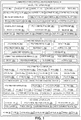
- FIG. 1 is an illustration of a functional block diagram showing exemplary versions of a laminated hybrid metallized polymer film 10 of the disclosure
- FIG. 2 is an illustration of a functional block diagram showing an exemplary version of a system 12 of the disclosure, where the system 12 incorporates versions of the laminated hybrid metallized polymer films 10.
- the laminated hybrid metallized polymer film 10 for erosion protection 14 (see FIG. 2 ), such as erosion edge protection 14a (see FIG. 2 ), from one or more erosion conditions 16 (see FIG. 2 ), for example, an airstream 18 (see FIG. 2 ), such as an external airstream 18a (see FIG. 2 ), to prevent or minimize delamination 20, of a composite structure 22 (see FIG. 2 ), such as an aircraft composite structure 24 (see FIG. 2 ).
- the laminated hybrid metallized polymer film 10 (see FIGS. 1 , 2 ) is preferably applied over and to a surface 26 (see FIG. 2 ), such as a substrate surface 28 (see FIG. 2 ), of the composite structure 22.
- a surface 26 see FIG. 2
- the laminated hybrid metallized polymer film 10 applied over and to the surface 26, such as the substrate surface 28 provides erosion protection 14 of the composite structure 22 from the one or more erosion conditions 16.
- the laminated hybrid metallized polymer film 10 may be manufactured, or processed, in a form 30, such as a tape 32, including a tape roll 32a, or a tape strip 32b.
- the laminated hybrid metallized polymer film 10 may be manufactured, or processed, in the form 30 of an applique 34, a sheet 36, an overlay 38, or another suitable form 30.
- the laminated hybrid metallized polymer film 10 comprises a metal foil layer 40.
- the metal foil layer 40 comprises a metal (met.) foil 42 (see FIG. 1 ).
- the metal foil 42 may be made of one or more metal materials 44, such as titanium (TI) 44a, titanium (TI) alloy 44b, nickel 44c, nickel alloy 44d, stainless steel (SS) 44e, stainless steel (SS) alloy 44f, aluminum (AL) 44g, aluminum (AL) alloy 44h, copper 44i, copper alloy 44j, or another suitable metal material 44. Although these metal materials 44 are preferred, other suitable metal materials 44 may also be used.
- the metal materials 44 used are preferably good for erosion protection. As further shown in FIG.
- the metal foil layer (FL) 40 comprises one of, a titanium foil layer (TI FL) 40a, for example a pure titanium foil layer, a titanium (TI) alloy foil layer (FL) 40b, a nickel foil layer (FL) 40c, a nickel alloy foil layer (FL) 40d, a stainless steel foil layer (SS FL) 40e, a stainless steel (SS) alloy foil layer (FL) 40f, an aluminum foil layer (AL FL) 40g, an aluminum (AL) alloy foil layer (FL) 40h, a copper foil layer (FL) 40i, a copper alloy foil layer (FL) 40j or another suitable metal foil layer 40. More preferably, the metal foil layer 40 comprises the titanium foil layer 40a.
- one or more surfaces 45 (see FIG. 1 ) of the metal foil layer 40 may be surface treated with one or more surface treatment processes 104 (see FIG. 2 ), to obtain one or more treated surfaces 45a (see FIG. 1 ), for example, to facilitate adhesion to a laminating adhesive layer 50 (see FIG. 1 ) of the laminated hybrid metallized polymer film 10.
- An example of a surface treatment process 104 that may be used includes a sol-gel process 106 (see FIG. 2 ) to treat or prepare the metal foil layer 40, such as a sol-gel process disclosed in U.S. Patent No. 5,939,197 , U.S. Patent No.
- the primer layer 47 may comprise a bond primer or an exterior primer, for example, an epoxy-based primer system, including a two-part system or a one-part system.
- the two-part system may comprise a urethane compatible epoxy primer, or another suitable two-part system.
- the urethane compatible epoxy primer may be used to protect metal foils 42 (see FIG.
- the one-part system may comprise an adhesive bond primer including a heat-curing adhesive bond primer, may comprise a corrosion inhibiting primer including a chromate-based modified epoxy primer, or may comprise another suitable one-part system.
- the epoxy-based primer system may contain corrosion inhibiting pigments, and some may be specifically formulated for composites.
- the primer layer 47 is preferably applied with a primer application process 118 (see FIG. 2 ).
- the metal foil layer 40 has a surface 45 that may be surface treated with a surface treatment process 104, to obtain a treated surface 45a, and the treated surface 45a of the metal foil layer 40 may be primed with a primer layer 47, prior to a polymer film layer 60 being laminated to the metal foil layer 40, or prior to the metal foil layer 40 being laminated to the polymer film layer 60.
- the metal foil layer 40 may be processed or modified prior to forming the laminated hybrid metallized polymer film 10.
- the metal foil layer 40 may have various configurations 46 (see FIG. 1 ).
- the metal foil layer 40 may have a configuration 46 comprising a plain metal foil 46a (see also FIG. 3A ), which is not processed or modified before application to the surface 26 (see FIG. 2 ), such as the substrate surface 28 (see FIG. 2 ), of the composite structure 22 (see FIG. 2 ).
- the metal foil layer 40 may be processed or modified and have a configuration 46 comprising one of, a slotted metal foil 46b (see also FIG. 3B ), a perforated metal foil 46c (see also FIG. 3C ), an expanded metal foil 46d (see also FIG. 3D ), a mesh metal foil 46e (see also FIG. 3E ), or another suitable configuration 46.
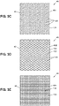
- the configurations 46 shown in FIGS. 3A-3E are discussed in further detail below.
- the metal foil layer 40 (see FIG. 1 ) has a thickness 48 (see FIG. 1 ) in a range of from 0.0001 inch (0.1 mil) to 0.020 inch (20 mils). More preferably, the metal foil layer 40 has a thickness 48 in a range of from 0.001 inch (1 mil) to 0.005 inch (5 mils).
- the laminated hybrid metallized polymer film 10 further comprises the laminating adhesive layer 50 underlying the metal foil layer 40.
- the laminating adhesive layer 50 comprises a laminating adhesive 52.
- the laminating adhesive 52 may be made of one or more laminating adhesive materials 54, such as urethane 54a including polyurethane 54b, epoxy 54c, polysiloxane 54d, silicone 54e, acrylic 54f, or another suitable laminating adhesive material 54. As shown in FIG.
- the laminating adhesive layer (AL) 50 may comprise one of, a urethane adhesive layer (AL) 50a including a polyurethane adhesive layer (AL) 50b , an epoxy adhesive layer (AL) 50c, a polysiloxane adhesive layer (AL) 50d, a silicone adhesive layer (AL) 50e, an acrylic adhesive layer (AL) 50f, or another suitable laminating adhesive layer 50.
- a urethane adhesive layer (AL) 50a including a polyurethane adhesive layer (AL) 50b , an epoxy adhesive layer (AL) 50c, a polysiloxane adhesive layer (AL) 50d, a silicone adhesive layer (AL) 50e, an acrylic adhesive layer (AL) 50f, or another suitable laminating adhesive layer 50.
- the laminating adhesive layer 50 has a thickness 56 (see FIG. 1 ) in a range of from 0.0001 inch (0.1 mil) to 0.0020 inch (2 mils). More preferably, the laminating adhesive layer 50 has a thickness 56 in a range of from 0.0001 inch (0.1 mil) to 0.0005 inch (0.5 mil).
- a laminator apparatus 58 (see FIG. 1 ), or machine, may be used to apply the laminating adhesive layer 50 to the metal foil layer 40 (see FIGS. 1-2 ), or to the polymer film layer 60 (see FIGS. 1-2 ), and may be used to press the metal foil layer 40, the laminating adhesive layer 50, and the polymer film layer 60 together in a lamination process 59 (see FIG. 2 ).
- the laminated hybrid metallized polymer film 10 further comprises the polymer film layer 60 underlying the laminating adhesive layer 50.
- the polymer film layer 60 is laminated to the metal foil layer 40 with the laminating adhesive layer 50, and the laminating adhesive layer 50 is coupled, or sandwiched, between the metal foil layer 40 and the polymer film layer 60, and holds or adheres the metal foil layer 40 to the polymer film layer 60.
- the polymer film layer 60 comprises a polymer film 62 (see FIG. 1 ).
- the polymer film 62 may be made of one or more polymer materials 64, such as polyether ether ketone (PEEK) 64a, polyester 64b, polyethylene terephthalate (PET) 64c, polypropylene (PP) 64d, polyethylene (PE) 64e, polytrimethylene terephthalate (PTT) 64f, polyamide (PA) 64g, polyetherimide (PEI) 64h, polyvinyl chloride (PVC) 64i, polycarbonate (PC) 64j, nylon 64k, polyetherketoneketone (PEKK) 64l, polyphenylsulfone (PPSU) 64m, polyphenylene sulfide (PPS) 64n, ethylene chlorotrifluoroethylene (ECTFE) 64o, polyvinylidene fluorine (PVDF) 64p, or another suitable polymer material 64.
- PEEK polyether ether ketone
- the polymer film layer (FL) 60 may comprise one of, a polyether ether ketone film layer (PEEK FL) 60a, a polyester film layer (FL) 60b, a polyethylene terephthalate film layer (PET FL) 60c, a polypropylene film layer (PP FL) 60d, a polyethylene film layer (PE FL) 60e, a polytrimethylene terephthalate film layer (PTT FL) 60f, a polyamide film layer (PA FL) 60g, a polyetherimide film layer (PEI FL) 60h, a polyvinyl chloride film layer (PVC FL) 60i, a polycarbonate film layer (PC FL) 60j, a nylon film layer (FL) 60k, a polyetherketoneketone film layer (PEKK FL) 60l, a polyphenylsulfone film layer (PPSU FL) 60m, a polyphenylene sulfide film layer (PPS FL) 60n
- PEEK FL polyether ether
- the polymer film layer 60 has a thickness 66 (see FIG. 1 ) in a range of from 0.0003 inch (0.3 mil) to 0.020 inch (20 mils). More preferably, the polymer film layer 60 has a thickness 66 in a range of from 0.001 inch (1 mil) to 0.005 inch (5 mils).
- the polymer film layer 60 may be in the form of an elastomeric polymer backing film 68 (see FIG. 1 ) that is laminated, or is configured to be laminated, to the metal foil layer 40, via the laminating adhesive layer 50, by using the lamination process 59 (see FIG. 2 ).
- the polymer film layer 60 (see FIG. 1 ), such as in the form of the elastomeric polymer backing film 68 (see FIG. 1 ), provides flexibility and handleability to the metal foil layer 40.
- the laminated hybrid metallized polymer film 10 further comprises an adhesive layer 70 underlying the polymer film layer 60.
- the adhesive layer 70 adheres the polymer film layer 60 to the surface 26 (see FIG. 2 ), such as the substrate surface 28 (see FIG. 2 ), of the composite structure 22 (see FIG. 2 ), such as the aircraft composite structure 24 (see FIG. 2 ).
- the adhesive layer (AL) 70 of the laminated hybrid metallized polymer film 10 may comprise one of, a sealant adhesive layer (AL) 72 including a polythioether sealant adhesive layer (AL) 72a, a polysulfide (PS) sealant adhesive layer (AL) 72b, or another suitable sealant adhesive layer 72.
- a sealant adhesive layer (AL) 72 including a polythioether sealant adhesive layer (AL) 72a, a polysulfide (PS) sealant adhesive layer (AL) 72b, or another suitable sealant adhesive layer 72.
- the adhesive layer 70 of the laminated hybrid metallized polymer film 10 may comprise a pressure sensitive adhesive (PSA) layer 74.
- the PSA layer 74 may comprise acrylic 74a (see FIG. 2 ), a modified (mod.) acrylic 74b (see FIG. 2 ), a silicone-based pressure sensitive adhesive (PSA) 74c (see FIG. 2 ), or another suitable PSA layer 74.
- the PSA layer 74 is preferably pre-applied to a hybrid metal film portion 80 (see FIG. 2 ) made up of the metal foil layer 40, the laminating adhesive layer 50, and the polymer film layer 60, and installation is a peel-and-stick process, like an applique.
- the adhesive layer 70 of the laminated hybrid metallized polymer film 10 may comprise a curable film adhesive layer (AL) 76 including a heat curable film adhesive layer (AL) 76a.
- the curable film adhesive layer 76 such as the heat curable film adhesive layer 76a, comprises epoxy film adhesives, such as toughened epoxy structural film adhesives, or another suitable film adhesive.
- the epoxy film adhesives such as the toughened epoxy structural film adhesives, provide high strength permanent structural bonds that are resistant to harsh environments and provide high durability.
- the heat curable film adhesive layer 76a preferably requires heat activation for cure and vacuum bagging for bond strength.
- the curable film adhesive layer 76, such as the heat curable film adhesive layer 76a may be supplied as part of the hybrid metal film portion 80 (see FIG. 2 ), or may be a separate material used for installation.
- the effective elevated temperature for heating and curing the heat curable film adhesive layer 76a (see FIGS. 1-2 ) and the hybrid metal film portion 80 (see FIG. 2 ) is preferably in a range of from 200°F (two-hundred degrees Fahrenheit) to 350°F (three-hundred fifty degrees Fahrenheit), and more preferably, in a range of from 200°F (two-hundred degrees Fahrenheit) to 275°F (two-hundred seventy-five degrees Fahrenheit), and most preferably, at a temperature of 250°F (two-hundred fifty degrees Fahrenheit).
- the effective pressure for heating and curing the heat curable film adhesive layer 76a (see FIGS. 1-2 ) and the hybrid metal film portion 80 (see FIG. 2 ) is preferably in a range of from 2 psi (two pounds per square inch) to 80 (eighty) psi, and more preferably, in a range of from 5 (five) psi to 20 (twenty) psi.
- the temperature, pressure, and time selected for the heating and curing is preferably selected based on the type of heat curable film adhesive layer 76a used.
- the adhesive layer 70 has a thickness 78 in a range of from 0.002 inch (2 mils) to 0.020 inch (20 mils). More preferably, the adhesive layer 70 has a thickness 78 in a range of from 0.005 inch (5 mils) to 0.010 inch (10 mils).
- the metal foil layer 40, the laminating adhesive layer 50, the polymer film layer 60, and the adhesive layer 70 form the laminated hybrid metallized polymer film 10.
- the metal foil layer 40, the laminating adhesive layer 50, and the polymer film layer 60 comprise the hybrid metal film portion 80 (see FIG. 2 ) of the laminated hybrid metallized polymer film 10, and the adhesive layer 70 comprises a bonding adhesive portion 81 (see FIG. 2 ) of the laminated hybrid metallized polymer film 10.
- the bonding adhesive portion 81 bonds, or is configured to bond, the hybrid metal film portion 80 to the surface 26, such as the substrate surface 28, of the composite structure 22, such as the aircraft composite structure 24.
- the system 12 comprises the composite structure 22, such as the aircraft composite structure 24.
- the aircraft composite structure 24 may comprise an aircraft composite part 24a (see FIG. 2 ), for example, a carbon fiber reinforced plastic (CFRP) part 24b (see FIG. 2 ), or a composite laminate 24c (see FIG. 2 ).
- the system 12 further comprises the surface 26, such as the substrate surface 28, of the composite structure 22, such as the aircraft composite structure 24.
- the composite structure 22, such as the aircraft composite structure 24, may have surfaces 26, such as the substrate surfaces 28, comprising curved surfaces 84, that each have a curved configuration 82 (see FIG. 2 ) with a complex curvature 83 (see FIG. 2 ). Installation or application of the laminated hybrid metallized polymer film 10 on such curved surfaces 84 is facilitated due to the formability of the laminated hybrid metallized polymer film 10.
- the surface 26, such as the substrate surface 28, of the composite structure 22, such as the aircraft composite structure 24, may have one or more edges 86, such as one or more leading edges 86a.
- the one or more edges 86 may include one or more cut edges 86b (see FIG. 2 ) with corners 88 (see FIG. 2 ), where the cut edges 86b and/or the corners 88 may protrude and may need to be covered with the laminated hybrid metallized polymer film 10, to protect against erosion conditions 16, and to prevent or minimize delamination 20 (see FIG. 2 ) of the one or more cut edges 86b.
- FIG. 2 the surface 26, such as the substrate surface 28, of the composite structure 22, such as the aircraft composite structure 24, may have one or more edges 86, such as one or more leading edges 86a.
- the one or more edges 86 may include one or more cut edges 86b (see FIG. 2 ) with corners 88 (see FIG. 2 ), where the cut edges 86b and/or the corners 88 may protrude and may need to be covered
- the laminated hybrid metallized polymer film 10 is preferably used on surfaces 26, such as the substrate surfaces 28, for example, a prepared substrate surfaces 28a, of one or more edges 86, such as one or more leading edges 86a, of composite structures 22, such as aircraft composite structures 24.
- the leading edges 86a may include leading edges 86a of wing panels 90, barrel sections 92, passenger doors 94, access doors 96, window surrounds 98, horizontal stabilizers 100, and vertical stabilizers 102 of air vehicles 160 (see FIG. 7 ), such as aircraft 160a (see FIG. 7 ).
- the surface 26, such as the substrate surface 28, may be prepared or treated with one or more surface treatment processes 104 (see FIG. 2 ), prior to application of the laminated hybrid metallized polymer film 10, to obtain the prepared substrate surface 28a (see FIG. 2 ).
- the one or more surface treatment processes 104 may facilitate adhesion of the laminated hybrid metallized polymer film 10 to the surface 26, such as the substrate surface 28.
- the system 12 may further comprise an edge seal layer 108 that may optionally be applied over and to the surface 26, such as the substrate surface 28, to become part of the prepared substrate surface 28a, prior to the laminated hybrid metallized polymer film 10 being applied over and to the surface 26, such as the substrate surface 28.
- the edge seal layer 108 comprises an edge seal material 110 that may comprise urethanes, thioethers, epoxies, polysulfides, or another suitable edge seal material 110.
- the edge seal layer 108 may be applied to, and smoothed over, the surface 26, such as the substrate surface 28.
- the edge seal layer 108 is preferably applied using an edge seal application process 112 (see FIG. 2 ).
- edge seal layer 108 After the edge seal layer 108 is applied to the surface 26, such as the substrate surface 28, the edge seal layer 108 may be cleaned and prepared for application of a primer layer 114 (see FIG. 2 ), or alternatively, for direct application of the laminated hybrid metallized polymer film 10.
- the edge seal layer 108 has a thickness 113 (see FIG. 2 ) in a range of from 0.0005 inch (0.5 mil) to 0.030 inch (30 mils). More preferably, the edge seal layer 108 has a thickness 113 in a range of from 0.001 inch (1 mil) to 0.005 inch (5 mils).
- the system 12 may further comprise the primer layer 114 that may be optionally applied over and to the edge seal layer 108, prior to the laminated hybrid metallized polymer film 10 being applied over and to the surface 26, such as the substrate surface 28, and to become part of the prepared substrate surface 28a.
- the primer layer 114 may comprise a primer material 116 comprising a bond primer or an exterior primer, for example, an epoxy-based primer system, including a two-part system or a one-part system.
- the two-part system may comprise a urethane compatible epoxy primer, or another suitable two-part system.
- the one-part system may comprise an adhesive bond primer including a heat-curing adhesive bond primer, may comprise a corrosion inhibiting primer including a chromate-based modified epoxy primer, or may comprise another suitable one-part system.
- the epoxy-based primer system may contain corrosion inhibiting pigments, and some may be specifically formulated for composites.
- the primer layer 114 is preferably applied with a primer application process 118 (see FIG. 2 ). After the primer layer 114 is applied to and over the edge seal layer 108, the primer layer 114 may be cleaned and prepared for application of the laminated hybrid metallized polymer film 10.
- the primer layer 114 may be applied directly to and over the surface 26, such as the substrate surface 28, without using the edge seal layer 108.
- neither the edge seal layer 108 nor the primer layer 114 is used, and the laminated hybrid metallized polymer film 10 is applied directly to the surface 26, such as the substrate surface 28, for example, the prepared substrate surface 28a, of the composite structure 22, such as the aircraft composite structure 24.
- the primer layer 114 has a thickness 119 (see FIG. 2 ) in a range of from 0.001 inch (1 mil) to 0.020 inch (20 mils). More preferably, the primer layer 114 has a thickness 119 in a range of from .005 inch (5 mils) to 0.010 inch (10 mils).
- the system 12 (see FIG. 2 ) comprises one or more versions of the laminated hybrid metallized polymer film 10, as discussed above, applied over and to the surface 26, such as the substrate surface 28, for example, the prepared substrate surface 28a, of the composite structure 22, such as the aircraft composite structure 24, with or without the edge seal layer 108 and/or the primer layer 114.
- the laminated hybrid metallized polymer film 10 comprises the metal foil layer 40.
- the metal foil layer 40 preferably comprises a titanium foil layer 40a, a titanium alloy foil layer 40b, a nickel foil layer 40c, a nickel alloy foil layer 40d, a stainless steel foil layer 40e, a stainless steel alloy foil layer 40f, an aluminum foil layer 40g, an aluminum alloy foil layer 40h, a copper foil layer 40i, a copper alloy foil layer 40j, or another suitable metal foil layer 40. More preferably, the metal foil layer 40 comprises the titanium foil layer 40a.
- the laminated hybrid metallized polymer film 10 further comprises the laminating adhesive layer 50 underlying the metal foil layer 40.
- the laminating adhesive layer 50 may comprise a urethane adhesive layer 50a including a polyurethane adhesive layer 50b, an epoxy adhesive layer 50c, a polysiloxane adhesive layer 50d, a silicone adhesive layer 50e, an acrylic adhesive layer 50f, or another suitable laminating adhesive layer 50.
- the laminated hybrid metallized polymer film 10 further comprises the polymer film layer 60 underlying the laminating adhesive layer 50.
- the polymer film layer 60 is laminated to the metal foil layer 40 with the laminating adhesive layer 50, and the laminating adhesive layer 50 is coupled between the metal foil layer 40 and the polymer film layer 60. As shown in FIG.
- the polymer film layer 60 may comprise a polyether ether ketone (PEEK) film layer 60a, a polyester film layer 60b, a polyethylene terephthalate (PET) film layer 60c, a polypropylene (PP) film layer 60d, a polyethylene (PE) film layer 60e, a polytrimethylene terephthalate (PTT) film layer 60f, a polyamide (PA) film layer 60g, a polyetherimide (PEI) film layer 60h, a polyvinyl chloride (PVC) film layer 60i, a polycarbonate (PC) film layer 60j, a nylon film layer 60k, a polyetherketoneketone (PEKK) film layer 60l, a polyphenylsulfone (PPSU) film layer 60m, a polyphenylene sulfide (PPS) film layer 60n, an ethylene chlorotrifluoroethylene (ECTFE) film layer 60o, a polyvinylidene fluorine (PEEK
- the laminated hybrid metallized polymer film 10 further comprises the adhesive layer 70 underlying the polymer film layer 60.
- the adhesive layer 70 adheres the polymer film layer 60 to the surface 26 (see FIG. 2 ), such as the substrate surface 28 (see FIG. 2 ) of the composite structure 22 (see FIG. 2 ), such as the aircraft composite structure 24 (see FIG. 2 ).
- the adhesive layer 70 of the laminated hybrid metallized polymer film 10 may comprise the sealant adhesive layer 72 including the polythioether sealant adhesive layer 72a, the polysulfide sealant adhesive layer 72b, or another suitable sealant adhesive layer 72.
- the adhesive layer 70 of the laminated hybrid metallized polymer film 10 may comprise the pressure sensitive adhesive (PSA) layer 74.
- the adhesive layer 70 of the laminated hybrid metallized polymer film 10 may comprise the curable film adhesive layer 76 including the heat curable film adhesive layer 76a.
- the metal foil layer 40, the laminating adhesive layer 50, the polymer film layer 60, and the adhesive layer 70 form the laminated hybrid metallized polymer film 10.
- the laminated hybrid metallized polymer film 10 is preferably applied over and to the surface 26 (see FIG. 2 ), such as the substrate surface 28 (see FIG. 2 ) of the composite structure 22 (see FIG. 2 ), such as the aircraft composite structure 24 (see FIG. 2 ).
- the composite structure 22 such as the aircraft composite structure 24
- the laminated hybrid metallized polymer film 10 applied over and to the surface 26, such as the substrate surface 28 provides erosion protection 14 (see FIG. 2 ), such as erosion edge protection 14a (see FIG. 2 ), of the composite structure 22, such as the aircraft composite structure 24, from the one or more erosion conditions 16, such as an airstream 18 (see FIG. 2 ), for example, an external airstream 18a (see FIG. 2 ).
- FIGS. 3A-3E various configurations 46 of the metal foil layer 40 are shown.
- the metal foil layer 40 may be processed or modified prior to forming the laminated hybrid metallized polymer film 10.
- the metal foil layer 40 may be processed or modified prior to forming the laminated hybrid metallized polymer film 10.
- FIG. 3A is an illustration of a top view of the metal foil layer 40 having a configuration 46 comprising a plain metal foil 46a that may be used in a version of the laminated hybrid metallized polymer film 10 (see FIG. 1 ) of the disclosure.
- the plain metal foil 46a shown in FIG. 2A , has not been processed or modified further and has a closed continuous surface 120 without any slots, perforations, openings, or patterns.
- FIG. 3B is an illustration of a top view of the metal foil layer 40 with a configuration 46 comprising a slotted metal foil 46b that may be used in a version of a laminated hybrid metallized polymer film 10 (see FIG. 1 ) of the disclosure.
- the slotted metal foil 46b has a plurality of slots 122 formed through a surface 124 of the slotted metal foil 46b.
- the slotted metal foil 46b may be formed by cutting with a slot cutting apparatus the plurality of slots 122, or elongated holes, in a staggered or side-by-side pattern, or another suitable pattern.
- FIG. 3C is an illustration of a top view of the metal foil layer 40 with a configuration 46 comprising a perforated metal foil 46c that may be used in a version of a laminated hybrid metallized polymer film 10 (see FIG. 1 ) of the disclosure.
- the perforated metal foil 46c has a plurality of perforations 126 formed through a surface 128 of the perforated metal foil 46c.
- the perforated metal foil 46c may be formed by cutting or punching with a hole cutting machine the plurality of perforations 126, or holes, in straight rows or a staggered pattern, or another suitable pattern.
- FIG. 3D is an illustration of a top view of the metal foil layer 40 with a configuration 46 comprising an expanded metal foil 46d that may be used in a version of a laminated hybrid metallized polymer film 10 (see FIG. 1 ) of the disclosure.
- the expanded metal foil 46d has a plurality of openings 130 in a diamond-shaped pattern 132 formed through a surface 134 of the expanded metal foil 46d.
- the expanded metal foil 46d may be formed by cutting with a slot cutting machine multiple slits in the metal foil layer 40, and then stretching the metal foil layer 40 that has been cut, to form the diamond-shaped pattern 132.
- FIG. 3E is an illustration of a top view of the metal foil layer 40 with a configuration 46 comprising a mesh metal foil 46e that may be used in a version of a laminated hybrid metallized polymer film 10 (see FIG. 1 ) of the disclosure.
- the mesh metal foil 46e has a woven mesh pattern 136 formed on, or in, a surface 138 of the mesh metal foil 46e with a metal mesh forming machine.
- FIG. 4A is a schematic cross-sectional side view of an exemplary version of a laminated hybrid metallized polymer film 10, such as in the form of laminated hybrid metallized polymer film 10a, of the disclosure.
- FIG. 4B is a schematic cross-sectional side view of the laminated hybrid metallized polymer film 10, such as in the form of laminated hybrid metallized polymer film 10a, of FIG. 4A , applied to a version of a substrate surface 28, such as a prepared substrate surface 28a.
- FIG. 4C is a schematic cross-sectional side view of the laminated hybrid metallized polymer film 10, such as in the form of laminated hybrid metallized polymer film 10a, of FIG. 4A , applied to another version of a substrate surface 28, such as the prepared substrate surface 28a.
- the laminated hybrid metallized polymer film 10 comprises the metal foil layer 40, the laminating adhesive layer 50, the polymer film layer 60, and the adhesive layer 70, where the adhesive layer 70 comprises a sealant adhesive layer 72.
- the sealant adhesive layer 72 may comprise a polythioether sealant adhesive layer 72a (see FIG. 1 ), a polysulfide sealant adhesive layer 72b (see FIG. 1 ), or another suitable sealant adhesive layer 72.
- the metal foil layer 40 has a first side 140a and a second side 140b
- the laminating adhesive layer 50 has a first side 142a and a second side 142b
- the polymer film layer 60 has a first side 144a and a second side 144b
- the adhesive layer 70 such as the sealant adhesive layer 72
- the second side 140b of the metal foil layer 40 is adjacent to, and coupled or attached to, the first side 142a of the laminating adhesive layer 50
- the second side 142b of the laminating adhesive layer 50 is adjacent to, and coupled or attached to, the first side 144a of the polymer film layer 60.
- the second side 144b of the polymer film layer 60 is adjacent to, and coupled or attached to, the first side 146a of the sealant adhesive layer 72.
- FIG. 4B shows the system 12, such as in the form of system 12a, comprising the laminated hybrid metallized polymer film 10, such as in the form of laminated hybrid metallized polymer film 10a, and the composite structure 22 with the substrate surface 28, such as the prepared substrate surface 28a.
- FIG. 4B further shows the edge seal layer 108 applied over and to the substrate surface 28, and shows the primer layer 114 applied over and to the edge seal layer 108.
- the primer layer 114 has a first side 148a and a second side 148b
- the edge seal layer 108 has a first side 150a and a second side 150b.
- laminated hybrid metallized polymer film 10 is applied directly to the primer layer 114.
- the second side 146b (see FIG. 4A ) of the sealant adhesive layer 72 is adjacent to, and coupled or attached to, the first side 148a of the primer layer 114.
- the second side 148b of the primer layer 114 is adjacent to, and coupled or attached to, the first side 150a of the edge seal layer 108, and the second side 150b of the edge seal layer 108 is adjacent to, and coupled or attached to, the substrate surface 28, such as the prepared substrate surface 28a, of the composite structure 22.
- FIG. 4C shows the system 12, such as in the form of system 12b, comprising the laminated hybrid metallized polymer film 10, such as in the form of laminated hybrid metallized polymer film 10a, and the composite structure 22 with the substrate surface 28, such as the prepared substrate surface 28a, but with no primer layer 114 (see FIG. 4B ) and with no edge seal layer 108 (see FIG. 4B ) on the substrate surface 28.
- FIG. 4C shows the laminated hybrid metallized polymer film 10, such as in the form of laminated hybrid metallized polymer film 10a, applied directly to the substrate surface 28, such as the prepared substrate surface 28a.
- the second side 146b (see FIG. 4A ) of the sealant adhesive layer 72 is adjacent to, and coupled or attached to, the substrate surface 28, such as the prepared substrate surface 28a, of the composite structure 22.
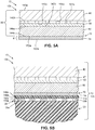
- FIG. 5A is a schematic cross-sectional side view of another exemplary version of a laminated hybrid metallized polymer film 10, such as in the form of laminated hybrid metallized polymer film 10b, of the disclosure.
- FIG. 5B is a schematic cross-sectional side view of the laminated hybrid metallized polymer film 10, such as in the form of laminated hybrid metallized polymer film 10b, of FIG. 5A , applied to a version of a substrate surface 28, such as a prepared substrate surface 28a.
- FIG. 5C is a schematic cross-sectional side view of the laminated hybrid metallized polymer film 10, such as in the form of laminated hybrid metallized polymer film 10b, of FIG. 5A , applied to another version of a substrate surface 28, such as the prepared substrate surface 28a.
- the laminated hybrid metallized polymer film 10 such as in the form of laminated hybrid metallized polymer film 10a, comprises the metal foil layer 40 that has been surface treated and primed with a primer layer 47, and comprises the laminating adhesive layer 50, the polymer film layer 60, and the adhesive layer 70, where the adhesive layer 70 comprises a pressure sensitive adhesive (PSA) layer 74.
- PSA layer 74 (see FIG. 5B ) comprising the bonding adhesive portion 81 (see FIG. 5B ), is preferably pre-applied to the hybrid metal film portion 80 (see FIG. 5B ), and installation is preferably a peel-and-stick process, for example, in the form 30 (see FIG. 1 ) of an applique 34 (see FIG. 1 ).
- the metal foil layer 40 has the first side 140a and the second side 140b
- the primer layer 47 of the metal foil layer 40 has a first side 151a and a second side 151b
- the laminating adhesive layer 50 has the first side 142a and the second side 142b
- the polymer film layer 60 has the first side 144a and the second side 144b
- the adhesive layer 70 such as the PSA layer 74, has a first side 152a and a second side 152b.
- the second side 140b of the metal foil layer 40 is adjacent to, and coupled or attached to, the first side 151a of the primer layer 47
- the second side 151b of the primer layer 47 is adjacent to, and coupled or attached to, the first side 142a of the laminating adhesive layer 50
- the second side 142b of the laminating adhesive layer 50 is adjacent to, and coupled or attached to, the first side 144a of the polymer film layer 60.
- the second side 144b of the polymer film layer 60 is adjacent to, and coupled or attached to, the first side 152a of the PSA layer 74.
- FIG. 5B shows the system 12, such as in the form of system 12c, comprising the laminated hybrid metallized polymer film 10, such as in the form of laminated hybrid metallized polymer film 10b, and the composite structure 22 with the substrate surface 28, such as the prepared substrate surface 28a.
- FIG. 5B further shows the edge seal layer 108 applied over and to the substrate surface 28, and shows the primer layer 114 applied over and to the edge seal layer 108.
- the primer layer 114 has the first side 148a and the second side 148b
- the edge seal layer 108 has the first side 150a and the second side 150b.
- laminated hybrid metallized polymer film 10 is applied directly to the primer layer 114.
- the second side 152b (see FIG. 5A ) of the PSA layer 74 (see FIGS. 5A, 5B ) is adjacent to, and coupled or attached to, the first side 148a of the primer layer 114.
- the second side 148b of the primer layer 114 is adjacent to, and coupled or attached to, the first side 150a of the edge seal layer 108
- the second side 150b of the edge seal layer 108 is adjacent to, and coupled or attached to, the substrate surface 28, such as the prepared substrate surface 28a, of the composite structure 22.
- FIG. 5C shows the system 12, such as in the form of system 12d, comprising the laminated hybrid metallized polymer film 10, such as in the form of laminated hybrid metallized polymer film 10b, and the composite structure 22 with the substrate surface 28, such as the prepared substrate surface 28a, but with no primer layer 114 (see FIG. 5B ) and with no edge seal layer 108 (see FIG. 5B ) on the substrate surface 28.
- FIG. 5C shows the laminated hybrid metallized polymer film 10, such as in the form of laminated hybrid metallized polymer film 10b, applied directly to the substrate surface 28, such as the prepared substrate surface 28a.
- the second side 152b (see FIG. 5A ) of the PSA layer 74 is adjacent to, and coupled or attached to, the substrate surface 28, such as the prepared substrate surface 28a, of the composite structure 22.
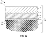
- FIG. 6A is a schematic cross-sectional side view of yet another exemplary version of a laminated hybrid metallized polymer film 10, such as in the form of laminated hybrid metallized polymer film 10c, of the disclosure.
- FIG. 6B is a schematic cross-sectional side view of the laminated hybrid metallized polymer film 10, such as in the form of laminated hybrid metallized polymer film 10c, of FIG. 6A , applied to a version of a substrate surface 28, such as a prepared substrate surface 28a.
- FIG. 6C is a schematic cross-sectional side view of the laminated hybrid metallized polymer film 10, such as in the form of laminated hybrid metallized polymer film 10c, of FIG. 6A , applied to another version of a substrate surface 28, such as the prepared substrate surface 28a.
- the laminated hybrid metallized polymer film 10 comprises the metal foil layer 40, the laminating adhesive layer 50, the polymer film layer 60, and the adhesive layer 70, where the adhesive layer 70 comprises a curable film adhesive layer 76.
- the curable film adhesive layer 76 (see FIGS. 1 , 6A ) may comprise a heat curable film adhesive layer 76a (see FIG. 1 ), or another suitable curable film adhesive layer 76.
- the heat curable film adhesive layer 76a requires heat activation for cure and vacuum bagging for bond strength.
- the metal foil layer 40 has the first side 140a and the second side 140b
- the laminating adhesive layer 50 has the first side 142a and the second side 142b
- the polymer film layer 60 has the first side 144a and the second side 144b
- the adhesive layer 70 such as the curable film adhesive layer 76
- the second side 140b of the metal foil layer 40 is adjacent to, and coupled or attached to, the first side 142a of the laminating adhesive layer 50
- the second side 142b of the laminating adhesive layer 50 is adjacent to, and coupled or attached to, the first side 144a of the polymer film layer 60.
- the second side 144b of the polymer film layer 60 is adjacent to, and coupled or attached to, the first side 154a of the curable film adhesive layer 76.
- FIG. 6B shows the system 12, such as in the form of system 12e, comprising the laminated hybrid metallized polymer film 10, such as in the form of laminated hybrid metallized polymer film 10c, and the composite structure 22 with the substrate surface 28, such as the prepared substrate surface 28a.
- FIG. 6B further shows the edge seal layer 108 applied over and to the substrate surface 28, and shows the primer layer 114 applied over and to the edge seal layer 108.
- the primer layer 114 has the first side 148a and the second side 148b
- the edge seal layer 108 has the first side 150a and the second side 150b.
- laminated hybrid metallized polymer film 10 is applied directly to the primer layer 114.
- the second side 154b (see FIG. 6A ) of the curable film adhesive layer 76 is adjacent to, and coupled or attached to, the first side 148a of the primer layer 114.
- the second side 148b of the primer layer 114 is adjacent to, and coupled or attached to, the first side 150a of the edge seal layer 108, and the second side 150b of the edge seal layer 108 is adjacent to, and coupled or attached to, the substrate surface 28 of the composite structure 22.
- FIG. 6C shows the system 12, such as in the form of system 12f, comprising the laminated hybrid metallized polymer film 10, such as in the form of laminated hybrid metallized polymer film 10c, and the composite structure 22 with the substrate surface 28, such as the prepared substrate surface 28a, but with no primer layer 114 (see FIG. 6B ) and with no edge seal layer 108 (see FIG. 6B ) on the substrate surface 28.
- FIG. 6C shows the laminated hybrid metallized polymer film 10, such as in the form of laminated hybrid metallized polymer film 10c, applied directly to the substrate surface 28, such as the prepared substrate surface 28a.
- the second side 154b (see FIG. 6A ) of the curable film adhesive layer 76 is adjacent to, and coupled or attached to, the substrate surface 28, such as the prepared substrate surface 28a, of the composite structure 22.
- FIG. 5A An example of a version of a laminated hybrid metallized polymer film 10, such as in the form of laminated hybrid metallized polymer film 10b (see FIG. 5A ), that includes a pressure sensitive adhesive (PSA) layer, was formed.
- Two (2) pieces of 0.0015 inch thick commercially pure titanium (CP Ti) metal foil were cleaned and surface treated with a sol-gel process, and primed with a primer layer.
- the titanium foil layer was then laminated, using a laminating adhesive in the form of a two-part urethane adhesive layer, to a 0.0015 inch thick polymer film layer in the form of a polyetheretherketone (PEEK) film layer, backed with a pressure sensitive adhesive (PSA) layer.
- PEEK polyetheretherketone
- the lamination process of laminating the titanium foil layer to the PEEK film layer was performed using a laboratory-scale Mayer rod drawdown coating system. Larger scale quantities of this lamination may be fabricated using industrial roll-to-roll systems.
- the laminated hybrid metallized polymer film formed was then installed on substrate surface edges of a candidate carbon fiber reinforced plastic (CFRP) part to make a prototype part. Installation of the laminated hybrid metallized polymer film was fast and simple, due to the handleability of the laminated hybrid metallized polymer film.
- the PSA layer acted as a polymer backing film and added flexibility to the hybrid metal film portion of the titanium metal foil laminated to the PEEK film layer, and made it easier to install the titanium metal foil portion without creasing or other possible unintended damage.
- the use of the PSA layer greatly simplified the adhering process to the substrate surface edges of the CFRP part.
- the laminated hybrid metallized polymer film would be particularly appropriate in areas that do not have significant fluid exposure, as PSA adhesives have limited fluid exposure.
- the laminated hybrid metallized polymer film provided erosion edge protection to the substrate surface edges of the CFRP part (composite structure) that were covered by the laminated hybrid metallized polymer film.
- FIG. 7 is an illustration of a perspective view of an air vehicle 160, such as in the form of aircraft 160a, that includes one or more versions of the laminated hybrid metallized polymer film 10 of the disclosure applied to one or more composite structures 22, such as one or more aircraft composite parts 24a.
- the air vehicle 160 such as in the form of aircraft 160a, comprises a fuselage 162, a nose 164, a cockpit 166, wings 168 coupled to the fuselage 162, engines 170, and a tail 172 including a first tail portion 174, for example, a vertical stabilizer 102, and second tail portions 176, for example, horizontal stabilizers 100.
- the laminated hybrid metallized polymer film 10 may preferably be used to cover one or more leading edges 86a, of composite structures 22, such as aircraft composite structures 24.
- the leading edges 86a that may be covered may include leading edges 86a of wing panels 90, barrel sections 92, passenger doors 94, access doors 96, window surrounds 98, horizontal stabilizers 100, and vertical stabilizers 102 of the air vehicle 160, such as the aircraft 160a.
- the composite structure 22 (see FIG. 7 ) comprises the aircraft composite structure 24 (see FIG. 7 ) on the air vehicle 160 (see FIG. 7 ), such as the aircraft 160a (see FIG. 7 ).
- the composite structure 22 may comprise a rotorcraft composite structure on a rotorcraft, a spacecraft composite structure on a spacecraft, a satellite composite structure on a satellite, a watercraft composite structure on a watercraft, an automobile composite structure on an automobile, a truck composite structure on a truck, a windmill blade composite structure on a windmill, or another suitable composite structure 22.
- FIG. 8 is an illustration of a flow diagram of a version of a method 200 of the disclosure.
- FIG. 8 represent operations and/or portions thereof, or elements, and lines connecting the various blocks do not imply any particular order or dependency of the operations or portions thereof, or elements.
- FIG. 8 and the disclosure of the steps of the method 200 set forth herein should not be interpreted as necessarily determining a sequence in which the steps are to be performed. Rather, although one illustrative order is indicated, it is to be understood that the sequence of the steps may be modified when appropriate. Accordingly, certain operations may be performed in a different order or simultaneously.
- the method 200 comprises the step of forming 202 a laminated hybrid metallized polymer film 10 (see FIG. 1 ).
- the laminated hybrid metallized polymer film 10 comprises a metal foil layer 40 (see FIG. 1 ), a laminating adhesive layer 50 (see FIG. 1 ) underlying the metal foil layer 40, and a polymer film layer 60 (see FIG. 1 ) underlying the laminating adhesive layer 50, where the metal foil layer 40, the laminating adhesive layer 50, and the polymer film layer 60 preferably comprise the hybrid metal film portion 80 (see FIG. 2 ) of the laminated hybrid metallized polymer film 10.
- the polymer film layer 60 is laminated to the metal foil layer 40 with the laminating adhesive layer 50 coupled between the metal foil layer 40 and the polymer film layer 60.
- the laminated hybrid metallized polymer film 10 further comprises an adhesive layer 70 (see FIG. 1 ) underlying the polymer film layer 60.
- the forming 202 (see FIG. 8 ) step of the method 200 (see FIG. 8 ) may further comprise forming the laminated hybrid metallized polymer film 10 (see FIG. 1 ) with the metal foil layer 40 preferably comprising one of, a titanium foil layer 40a, a titanium alloy foil layer 40b, a nickel foil layer 40c a nickel alloy foil layer 40d, a stainless steel foil layer 40e, a stainless steel alloy foil layer 40f, an aluminum foil layer 40g, an aluminum alloy foil layer 40h, a copper foil layer 40i, a copper alloy foil layer 40j, or another suitable metal foil layer 40. More preferably, the metal foil layer 40 comprises the titanium foil layer 40a.
- the forming 202 (see FIG. 8 ) step of the method 200 may further comprise surface treating a surface 45 (see FIG. 1 ) of the metal foil layer 40 (see FIGS. 1-2 ) with a surface treatment process 104 (see FIG. 2 ), to obtain a treated surface 45a (see FIG. 1 ), and priming the treated surface 45a of the metal foil layer 40 with a primer layer 47 (see FIG. 1 ), prior to the polymer film layer 60 being laminated to the metal foil layer 40, and prior to obtaining the formed laminated hybrid metallized polymer film 10.
- One or more surfaces 45 (see FIG. 1 ) of the metal foil layer 40 for example, a second side 140b (see FIG.
- a surface treatment process 104 that may be used includes a sol-gel process 106 (see FIG. 2 ) to treat or prepare the metal foil layer 40, such as a sol-gel process disclosed in U.S. Patent No. 5,939,197 , U.S. Patent No. 5,958,578 , and U.S. Patent No. 6,797,376 .
- ⁇ treatment processes 104 may also be used to surface treat the metal foil layer 40 prior to undergoing a lamination process 59 (see FIG. 2 ).
- the one or more treated surfaces 45a of the metal foil layer 40 may then be primed with a primer layer 47 (see FIGS. 1 , 5A ).
- the primer layer 47 is preferably applied with a primer application process 118 (see FIG. 2 ).
- the forming 202 (see FIG. 8 ) step of the method 200 may further comprise processing or modifying the metal foil layer 40 prior to the polymer film layer 60 being laminated to the metal foil layer 40, and prior to obtaining the formed laminated hybrid metallized polymer film 10.
- the metal foil layer 40 may have various configurations 46 (see FIG. 1 ). As shown in FIG. 1 , the metal foil layer 40 may have a configuration 46 comprising a plain metal foil 46a (see also FIG. 3A ), which is not processed or modified before application to the surface 26 (see FIG. 2 ), such as the substrate surface 28 (see FIG. 2 ), of the composite structure 22 (see FIG. 2 ). Alternatively, as shown in FIG.
- the metal foil layer 40 may be processed or modified and have a configuration 46 comprising one of, a slotted metal foil 46b (see also FIG. 3B ), a perforated metal foil 46c (see also FIG. 3C ), an expanded metal foil 46d (see also FIG. 3D ), a mesh metal foil 46e (see also FIG. 3E ), or another suitable configuration 46.
- the forming 202 (see FIG. 8 ) step of the method 200 (see FIG. 8 ) may further comprise forming the laminated hybrid metallized polymer film 10 with the laminating adhesive layer 50 (see FIG. 1 ) comprising one of, a urethane adhesive layer 50a (see FIG. 1 ) including a polyurethane adhesive layer 50b (see FIG. 1 ), an epoxy adhesive layer 50c (see FIG. 1 ), a polysiloxane adhesive layer 50d (see FIG. 1 ), a silicone adhesive layer 50e (see FIG. 1 ), an acrylic adhesive layer 50f (see FIG. 1 ), or another suitable laminating adhesive layer 50.
- the forming 202 (see FIG. 8 ) step of the method 200 see FIG.
- the polymer film layer 60 comprising one of, a polyether ether ketone (PEEK) film layer 60a, a polyester film layer 60b, a polyethylene terephthalate (PET) film layer 60c, a polypropylene (PP) film layer 60d, a polyethylene (PE) film layer 60e, a polytrimethylene terephthalate (PTT) film layer 60f, a polyamide (PA) film layer 60g, a polyetherimide (PEI) film layer 60h, a polyvinyl chloride (PVC) film layer 60i, a polycarbonate (PC) film layer 60j, a nylon film layer 60k, a polyetherketoneketone (PEKK) film layer 601, a polyphenylsulfone (PPSU) film layer 60m, a polyphenylene sulfide (PPS) film layer 60n, an ethylene chlorotrifluoroethylene (ECTFE)
- PEEK polyether ether ketone
- PET polyethylene
- the forming 202 (see FIG. 8 ) step of the method 200 (see FIG. 8 ) may further comprise forming the laminated hybrid metallized polymer film 10 with the adhesive layer 70 (see FIG. 1 ) comprising one of, a sealant adhesive layer 72 (see FIG. 1 ) including a polythioether sealant adhesive layer 72a (see FIG. 1 ), a polysulfide sealant adhesive layer 72b (see FIG. 1 ), or another suitable sealant adhesive layer 72; a pressure sensitive adhesive (PSA) layer 74 (see FIG. 1 ); a curable film adhesive layer 76 (see FIG. 1 ) including a heat curable film adhesive layer 76a (see FIG. 1 ), or another suitable adhesive layer 70.
- a sealant adhesive layer 72 see FIG. 1
- PSA pressure sensitive adhesive
- the laminated hybrid metallized polymer film 10 may be in the form 30 (see FIG. 1 ) of a tape 32 (see FIG. 1 ), including a tape roll 32a (see FIG. 1 ), or a tape strip 32b (see FIG. 1 ).
- the laminated hybrid metallized polymer film 10 may be the form 30 of an applique 34 (see FIG. 1 ), a sheet 36 (see FIG. 1 ), an overlay 38 (see FIG. 1 ), or another suitable form 30.
- the method 200 further comprises the step of preparing 204 a substrate surface 28 (see FIG. 2 ) of the composite structure 22 (see FIG. 2 ), such as an aircraft composite structure 24 (see FIG. 2 ), to obtain a prepared substrate surface 28a (see FIG. 2 ).
- the preparing 204 (see FIG. 8 ) step of the method 200 may comprise preparing 204 the substrate surface 28 of the composite structure 22 with one or more surface treatment processes 104 (see FIG. 2 ), such as cleaning, smoothing, polishing, or another suitable surface treatment processes 104.
- the preparing 204 (see FIG. 8 ) step of the method 200 may further comprise applying an edge seal layer 108 (see FIG.
- the laminated hybrid metallized polymer film 10 may be applied directed to the substrate surface 28, such as the prepared substrate surface 28a, without the edge seal layer 108 (see FIGS. 4B , 5B , 6B ) and the primer layer 114 (see FIGS. 4B , 5B , 6B ).
- the method 200 further comprises the step of applying 206 the laminated hybrid metallized polymer film 10 over and to the prepared substrate surface 28a (see FIG. 2 ) of the composite structure 22 (see FIG. 2 ), as the aircraft composite structure 24 (see FIG. 2 ).
- the adhesive layer 70 adheres the polymer film layer 60 to the prepared substrate surface 28a.
- the composite structure 22, such as the aircraft composite structure 24 is exposed to one or more erosion conditions 16 (see FIG. 2 )
- the laminated hybrid metallized polymer film 10 applied over and to the prepared substrate surface 28a provides erosion protection 14 (see FIG. 2 ) to the composite structure 22 from the one or more erosion conditions 16.
- the applying 206 (see FIG. 8 ) step of the method 200 further comprises applying the laminated hybrid metallized polymer film 10 over and to the prepared substrate surface 28a of the composite structure 22 comprising an aircraft composite structure 24 (see FIG. 2 ), and further wherein when the aircraft composite structure 24 is exposed to one or more erosion conditions 16 (see FIG. 2 ) including an airstream 18 (see FIG. 2 ), for example, an external airstream 18a (see FIG. 2 ), where the laminated hybrid metallized polymer film 10 is applied over and to the prepared substrate surface 28a to prevent or minimize delamination 20 (see FIG. 2 ) of one or more cut edges 86b (see FIG. 2 ) of the prepared substrate surface 28a and to provide erosion protection 14 of the aircraft composite structure 24 from the one or more erosion conditions 16 including the airstream 18.
- FIG. 9 is an illustration of a flow diagram of an exemplary aircraft manufacturing and service method 300
- FIG. 10 is an illustration of an exemplary block diagram of an aircraft 316.
- versions of the disclosure may be described in the context of the aircraft manufacturing and service method 300 as shown in FIG. 9
- the aircraft 316 as shown in FIG. 10 .
- exemplary aircraft manufacturing and service method 300 may include specification and design 302 of the aircraft 316 and material procurement 304. During manufacturing, component and subassembly manufacturing 306 and system integration 308 of the aircraft 316 takes place. Thereafter, the aircraft 316 may go through certification and delivery 310 in order to be placed in service 312. While in service 312 by a customer, the aircraft 316 may be scheduled for routine maintenance and service 314 (which may also include modification, reconfiguration, refurbishment, and other suitable services).
- Each of the processes of the aircraft manufacturing and service method 300 may be performed or carried out by a system integrator, a third party, and/or an operator (e.g., a customer).
- a system integrator may include, without limitation, any number of aircraft manufacturers and major-system subcontractors.
- a third party may include, without limitation, any number of vendors, subcontractors, and suppliers.
- An operator may include an airline, leasing company, military entity, service organization, and other suitable operators.
- the aircraft 316 produced by the exemplary aircraft manufacturing and service method 300 may include an airframe 318 with a plurality of systems 320 and an interior 322.
- the plurality of systems 320 may include one or more of a propulsion system 324, an electrical system 326, a hydraulic system 328, and an environmental system 330. Any number of other systems may be included.
- an aerospace example is shown, the principles of the disclosure may be applied to other industries, such as the automotive industry.
- Methods and systems embodied herein may be employed during any one or more of the stages of the aircraft manufacturing and service method 300.
- components or subassemblies corresponding to component and subassembly manufacturing 306 may be fabricated or manufactured in a manner similar to components or subassemblies produced while the aircraft 316 is in service 312.
- one or more apparatus embodiments, method embodiments, or a combination thereof may be utilized during component and subassembly manufacturing 306 and system integration 308, for example, by substantially expediting assembly of or reducing the cost of the aircraft 316.
- one or more of apparatus embodiments, method embodiments, or a combination thereof may be utilized while the aircraft 316 is in service 312, for example and without limitation, to maintenance and service 314.
- Disclosed embodiments of the laminated hybrid metallized polymer film 10 provide erosion protection 14 (see FIG. 2 ) from one or more erosion conditions 16 (see FIG. 2 ), for example, an airstream 18 (see FIG. 2 ), such as an external airstream 18a (see FIG. 2 ), to prevent or minimize delamination 20 (see FIG. 2 ), of a composite structure 22 (see FIG. 2 ), such as an aircraft composite structure 24 (see FIG. 2 ).
- the laminated hybrid metallized polymer film 10 see FIGS.
- the laminated hybrid metallized polymer film 10 (see FIGS. 1 , 4A , 5A , 6A ) has a hybrid metal film portion 80 (see FIG. 2 ) comprising a metal foil layer 40 (see FIGS. 1-2 ), such as a titanium foil layer 40a (see FIG. 2 ), that is very thin and lightweight, laminated with a laminating adhesive layer 50 (see FIGS. 1-2 ), to a polymer film layer 60 (see FIGS.
- the laminated hybrid metallized polymer film 10 further has a bonding adhesive portion 81 (see FIG. 2 ) that adheres or bonds the hybrid metal film portion 80 to a substrate surface 28 (see FIG. 2 ), such as a prepared substrate surface 28a (see FIG. 2 ), of the composite structure 22, such as the aircraft composite structure 24.
- the hybrid metal film portion 80 may be applied to the substrate surface 28 of the composite structure 22, such as the aircraft composite structure 24 using several options, including using a sealant adhesive layer 72 (see FIG. 2 ), using a pressure sensitive adhesive (PSA) layer 74 (see FIG. 2 ) similar to a peel-and-stick process, for example, an applique, or using a curable film adhesive layer 76 (see FIG. 2 ), such as a heat curable film adhesive layer (see FIG. 2 ).
- PSA pressure sensitive adhesive
- disclosed embodiments of the laminated hybrid metallized polymer film 10 provide a laminated hybrid metallized polymer film 10 (see FIGS. 1 , 4A , 5A , 6A ), the system 12 (see FIGS. 2 , 4B-4C , 5B-5C , 6B-6C ), and method 200 (see FIG. 8 ) provide a laminated hybrid metallized polymer film 10 (see FIGS. 1 , 4A , 5A , 6A ) or hybrid film product that is easy to handle, manipulate, cut, install, and apply to a surface 26 (see FIG. 2 ), such as a substrate surface 28, for example, a prepared substrate surface 28a (see FIG. 2 ), and leading edges 86a (see FIG. 2 ) and cut edges 86b (see FIG.
- the laminated hybrid metallized polymer film 10 preferably has improved handleability due to the flexibility of the polymer film layer 60 and the thinness and light weight of the metal foil layer 40 used, as compared to known thicker and heavier metal foil products applied to surfaces and leading edges of aircraft composite structures.
- the laminated hybrid metallized polymer film 10 has a thinner and lighter weight metal foil layer 40 that is easier to handle, with the polymer film layer 60 laminated to the metal foil layer 40, the cost of manufacturing and maintaining the laminated hybrid metallized polymer film 10 for erosion protection 14 is decreased, as compared to thicker and heavier metal foil products.
- disclosed embodiments of the laminated hybrid metallized polymer film 10 may be more easily formed over curved surfaces 84 (see FIG. 2 ) with complex curvature 83 (see FIG. 2 ), for example, leading edges 86a (see FIGS. 2 , 7 ) of wing panels 90 (see FIGS. 2 , 7 ), barrel sections 92 (see FIGS. 2 , 7 ), passenger doors 94 (see FIGS. 2 , 7 ), access doors 96 (see FIG. 2 ), window surrounds 98 (see FIGS. 2 , 7 ), horizontal stabilizers 100 (see FIGS. 2 , 7 ), and vertical stabilizers 102 (see FIGS. 2 , 7 ), of aircraft composite structures 24 (see FIGS. 2 , 7 ).
- secondary processing to form the metal material 44, such as titanium 44a, into a curved shape may no longer be needed.
- the laminated hybrid metallized polymer film 10 preferably maintains the excellent erosion capabilities and performance of the metal materials 44 (see FIG. 1 ), and in particular, of titanium 44a (see FIG. 1 ) and titanium alloy 44b, used for the metal foil layer 40, and may greatly reduce possible rework by mitigating any possible damage that might occur to the metal foil layer 40, prior to application on and to the composite structure 22, such as the aircraft composite structure 24.
- the metal foil layer 40 such as the titanium foil layer 40a and the titanium alloy foil layer 40b, serve as effective means to provide erosion protection 14 to cut edges 86b (see FIG. 2 ) of aircraft composite structures 24 (see FIGS. 2 , 7 ) that are exposed to one or more erosion conditions 16 (see FIG. 2 ), such as an airstream 18 (see FIG. 2 ), for example, an external airstream 18a (see FIG. 2 ).
- disclosed embodiments of the laminated hybrid metallized polymer film 10 provide a laminated hybrid metallized polymer film 10 that may be manufactured, or processed, in easily applied and flexible forms 30, such as a tape 32, including a tape roll 32a, or a tape strip 32b, an applique 34, a sheet 36, an overlay 38, or another suitable form 30.
- a laminated hybrid metallized polymer film 10 may be manufactured, or processed, in easily applied and flexible forms 30, such as a tape 32, including a tape roll 32a, or a tape strip 32b, an applique 34, a sheet 36, an overlay 38, or another suitable form 30.
- the ease of application of the laminated hybrid metallized polymer film 10 to the composite structures 22, such as the aircraft composite structures 24, may reduce the time and labor required to apply the laminated hybrid metallized polymer film 10, as compared to thicker and heavier metal foil products that may be labor intensive to apply, and thus, in turn, may reduce the cost of installation.
- the laminated hybrid metallized polymer film 10 may be easily removed and replaced as necessary for maintainability of the air vehicle 160 (see FIG. 7 ), such as the aircraft 160a (see FIG. 7 ), or another suitable vehicle or structure.
Landscapes
- Engineering & Computer Science (AREA)
- Mechanical Engineering (AREA)
- Aviation & Aerospace Engineering (AREA)
- Chemical & Material Sciences (AREA)
- Organic Chemistry (AREA)
- Laminated Bodies (AREA)
Abstract
Description
- The disclosure relates generally to hybrid films, hybrid film systems, and methods of forming the same, and more particularly, to laminated hybrid metallized polymer films, systems, and methods of forming the same, to provide erosion protection of composite structures, such as aircraft composite structures.
- Known systems and methods exist for providing erosion protection or edge protection of composite structures, such as aircraft composite structures. In such situations, the term "erosion" refers to physical changes to the composite as a result of exposure to an external airstream. For example, one known system and method includes use of strips of metal foil, such as titanium foil, adhered with a sealant to the cut edges of aircraft composite structures, to prevent any impact to the surface of the aircraft composite structures in an external airstream.
- However, such strips of titanium foil may be heavy, expensive, and required careful handling during processing and shipping. Moreover, the application process for applying such strips of titanium foil typically requires highly trained manufacturing technicians to manually apply the strips, and such manual application may present ergonomic issues. Further, for curved surfaces and corners of cut edges, the strips of titanium foil may need to be bent and formed into a desired shape to fit over the curved surfaces and corners. This may require custom tooling to form the strips of titanium foil into the desired shape for installation, and such custom tooling may increase manufacturing costs.
- Another known system and method for providing erosion protection or edge protection of composite structures, such as aircraft composite structures, includes a coating-based solution. Coatings may be either spray applied or roll applied over the edge surfaces of the composite structures, such as aircraft composite structures, to be protected. However, it may be challenging to apply such coatings in a precise area with precision thickness over long narrow surfaces. Further, care must be taken to ensure that acceptable coating coverage is achieved over cut edges and around corners of composite structures, such as aircraft composite structures, that have complex curvature.
- Accordingly, there is a need in the art for an apparatus, system, and method for providing erosion protection of composite structures, such as aircraft composite structures, that improve the ease of handling and installation, that are less expensive, and that provide advantages over known products, systems, and methods.
- Example implementations of the present disclosure provide a laminated hybrid metallized polymer film, system, and method for erosion protection of composite structures, such as aircraft composite structures. As discussed in the below detailed description, versions of the laminated hybrid metallized polymer film, system, and method may provide significant advantages over known products, systems, and methods.
- In a version of the disclosure, there is provided a laminated hybrid metallized polymer film for erosion protection of a composite structure. The laminated hybrid metallized polymer film comprises a metal foil layer. The laminated hybrid metallized polymer film further comprises a laminating adhesive layer underlying the metal foil layer.
- The laminated hybrid metallized polymer film further comprises a polymer film layer underlying the laminating adhesive layer. The polymer film layer is laminated to the metal foil layer with the laminating adhesive layer coupled between the metal foil layer and the polymer film layer. The laminated hybrid metallized polymer film further comprises an adhesive layer underlying the polymer film layer. The adhesive layer adheres the polymer film layer to a substrate surface of the composite structure.
- The metal foil layer, the laminating adhesive layer, the polymer film layer, and the adhesive layer form the laminated hybrid metallized polymer film, for application over and to the substrate surface of the composite structure.
- In another version of the disclosure, there is provided a system for erosion protection of an aircraft composite structure. The system comprises a substrate surface of the aircraft composite structure. The substrate surface has one or more cut edges. The system further comprises a laminated hybrid metallized polymer film applied over and to the substrate surface of the aircraft composite structure.
- The laminated hybrid metallized polymer film comprises a metal foil layer. The laminated hybrid metallized polymer film further comprises a laminating adhesive layer underlying the metal foil layer.
- The laminated hybrid metallized polymer film further comprises a polymer film layer underlying the laminating adhesive layer. The polymer film layer is laminated to the metal foil layer with the laminating adhesive layer coupled between the metal foil layer and the polymer film layer.
- The laminated hybrid metallized polymer film further comprises an adhesive layer underlying the polymer film layer, the adhesive layer adhering the polymer film layer to the substrate surface of the aircraft composite structure. When the aircraft composite structure is exposed to an airstream, the laminated hybrid metallized polymer film applied over and to the substrate surface provides erosion protection of the aircraft composite structure from the airstream.
- In another version of the disclosure, there is provided a method for providing erosion protection of a composite structure. The method comprises the step of forming a laminated hybrid metallized polymer film.
- The laminated hybrid metallized polymer film comprises a metal foil layer. The laminated hybrid metallized polymer film further comprises a laminating adhesive layer underlying the metal foil layer. The laminated hybrid metallized polymer film further comprises a polymer film layer underlying the laminating adhesive layer. The polymer film layer is laminated to the metal foil layer with the laminating adhesive layer coupled between the metal foil layer and the polymer film layer. The laminated hybrid metallized polymer film further comprises an adhesive layer underlying the polymer film layer.
- The method further comprises the step of preparing a substrate surface of the composite structure, to obtain a prepared substrate surface. The method further comprises the step of applying the laminated hybrid metallized polymer film over and to the prepared substrate surface of the composite structure. The adhesive layer adheres the polymer film layer to the prepared substrate surface. When the composite structure is exposed to one or more erosion conditions, the laminated hybrid metallized polymer film applied over and to the prepared substrate surface provides erosion protection to the composite structure from the one or more erosion conditions.
- The features, functions, and advantages that have been discussed can be achieved independently in various embodiments of the disclosure or may be combined in yet other embodiments further details of which can be seen with reference to the following description and drawings.
- The disclosure can be better understood with reference to the following detailed description taken in conjunction with the accompanying drawings which illustrate preferred and exemplary versions, but which are not necessarily drawn to scale, wherein:
-
FIG. 1 is an illustration of a functional block diagram showing exemplary versions of a laminated hybrid metallized polymer film of the disclosure; -
FIG. 2 is an illustration of a functional block diagram showing an exemplary version of a system of the disclosure; -
FIG. 3A is an illustration of a top view of a metal foil layer with a configuration comprising a plain metal foil that may be used in a version of a laminated hybrid metallized polymer film of the disclosure; -
FIG. 3B is an illustration of a top view of a metal foil layer with a configuration comprising a slotted metal foil that may be used in a version of a laminated hybrid metallized polymer film of the disclosure; -
FIG. 3C is an illustration of a top view of a metal foil layer with a configuration comprising a perforated metal foil that may be used in a version of a laminated hybrid metallized polymer film of the disclosure; -
FIG. 3D is an illustration of a top view of a metal foil layer with a configuration comprising an expanded metal foil that may be used in a version of a laminated hybrid metallized polymer film of the disclosure; -
FIG. 3E is an illustration of a top view of a metal foil layer with a configuration comprising a mesh metal foil that may be used in a version of a laminated hybrid metallized polymer film of the disclosure; -
FIG. 4A is a schematic cross-sectional side view of an exemplary version of a laminated hybrid metallized polymer film of the disclosure; -
FIG. 4B is a schematic cross-sectional side view of the laminated hybrid metallized polymer film ofFIG. 4A applied to a version of substrate surface; -
FIG. 4C is a schematic cross-sectional side view of the laminated hybrid metallized polymer film ofFIG. 4A applied to another version of a substrate surface; -
FIG. 5A is a schematic cross-sectional side view of another exemplary version of a laminated hybrid metallized polymer film of the disclosure; -
FIG. 5B is a schematic cross-sectional side view of the laminated hybrid metallized polymer film ofFIG. 5A applied to a version of a substrate surface; -
FIG. 5C is a schematic cross-sectional side view of the laminated hybrid metallized polymer film ofFIG. 5A applied to another version of a substrate surface; -
FIG. 6A is a schematic cross-sectional side view of yet another exemplary version of a laminated hybrid metallized polymer film of the disclosure; -
FIG. 6B is a schematic cross-sectional side view of the laminated hybrid metallized polymer film ofFIG. 6A applied to a version of a substrate surface; -
FIG. 6C is a schematic cross-sectional side view of the laminated hybrid metallized polymer film ofFIG. 6A applied to another version of a substrate surface; -
FIG. 7 is an illustration of a perspective view of an air vehicle that includes one or more versions of a laminated hybrid metallized polymer film of the disclosure; -
FIG. 8 is an illustration of a flow diagram of a version of a method of the disclosure; -
FIG. 9 is an illustration of a flow diagram of an exemplary aircraft manufacturing and service method; and -
FIG. 10 is an illustration of an exemplary block diagram of an aircraft. - The figures shown in this disclosure represent various aspects of the versions presented, and only differences will be discussed in detail.
- Disclosed versions or embodiments will now be described more fully hereinafter with reference to the accompanying drawings, in which some, but not all of the disclosed versions are shown. Indeed, several different versions may be provided and should not be construed as limited to the versions set forth herein. Rather, these versions are provided so that this disclosure will be thorough and fully convey the scope of the disclosure to those skilled in the art.
- Now referring to the Figures,
FIG. 1 is an illustration of a functional block diagram showing exemplary versions of a laminated hybrid metallizedpolymer film 10 of the disclosure, andFIG. 2 is an illustration of a functional block diagram showing an exemplary version of asystem 12 of the disclosure, where thesystem 12 incorporates versions of the laminated hybridmetallized polymer films 10. - In a version of the disclosure, there is provided the laminated hybrid metallized polymer film 10 (see
FIGS. 1 ,2 ) for erosion protection 14 (seeFIG. 2 ), such aserosion edge protection 14a (seeFIG. 2 ), from one or more erosion conditions 16 (seeFIG. 2 ), for example, an airstream 18 (seeFIG. 2 ), such as anexternal airstream 18a (seeFIG. 2 ), to prevent or minimizedelamination 20, of a composite structure 22 (seeFIG. 2 ), such as an aircraft composite structure 24 (seeFIG. 2 ). - The laminated hybrid metallized polymer film 10 (see
FIGS. 1 ,2 ) is preferably applied over and to a surface 26 (seeFIG. 2 ), such as a substrate surface 28 (seeFIG. 2 ), of thecomposite structure 22. When thecomposite structure 22 is exposed to one ormore erosion conditions 16, the laminated hybrid metallizedpolymer film 10 applied over and to thesurface 26, such as thesubstrate surface 28, provideserosion protection 14 of thecomposite structure 22 from the one ormore erosion conditions 16. - As shown in
FIG. 1 , the laminated hybrid metallizedpolymer film 10 may be manufactured, or processed, in aform 30, such as atape 32, including atape roll 32a, or a tape strip 32b. Alternatively, as shown inFIG. 1 , the laminated hybrid metallizedpolymer film 10 may be manufactured, or processed, in theform 30 of an applique 34, a sheet 36, an overlay 38, or anothersuitable form 30. - As shown in
FIGS. 1 ,2 , the laminated hybrid metallizedpolymer film 10 comprises ametal foil layer 40. Themetal foil layer 40 comprises a metal (met.) foil 42 (seeFIG. 1 ). As shown inFIG. 1 , themetal foil 42 may be made of one ormore metal materials 44, such as titanium (TI) 44a, titanium (TI)alloy 44b, nickel 44c,nickel alloy 44d, stainless steel (SS) 44e, stainless steel (SS)alloy 44f, aluminum (AL) 44g, aluminum (AL)alloy 44h, copper 44i,copper alloy 44j, or anothersuitable metal material 44. Although thesemetal materials 44 are preferred, othersuitable metal materials 44 may also be used. Themetal materials 44 used are preferably good for erosion protection. As further shown inFIG. 1 , preferably, the metal foil layer (FL) 40 comprises one of, a titanium foil layer (TI FL) 40a, for example a pure titanium foil layer, a titanium (TI) alloy foil layer (FL) 40b, a nickel foil layer (FL) 40c, a nickel alloy foil layer (FL) 40d, a stainless steel foil layer (SS FL) 40e, a stainless steel (SS) alloy foil layer (FL) 40f, an aluminum foil layer (AL FL) 40g, an aluminum (AL) alloy foil layer (FL) 40h, a copper foil layer (FL) 40i, a copper alloy foil layer (FL) 40j or another suitablemetal foil layer 40. More preferably, themetal foil layer 40 comprises thetitanium foil layer 40a. - In addition, one or more surfaces 45 (see
FIG. 1 ) of themetal foil layer 40, for example, asecond side 140b (seeFIG. 5A ) of themetal foil layer 40, may be surface treated with one or more surface treatment processes 104 (seeFIG. 2 ), to obtain one or more treatedsurfaces 45a (seeFIG. 1 ), for example, to facilitate adhesion to a laminating adhesive layer 50 (seeFIG. 1 ) of the laminated hybrid metallizedpolymer film 10. An example of asurface treatment process 104 that may be used includes a sol-gel process 106 (seeFIG. 2 ) to treat or prepare themetal foil layer 40, such as a sol-gel process disclosed inU.S. Patent No. 5,939,197 ,U.S. Patent No. 5,958,578 , andU.S. Patent No. 6,797,376 . However, other types of surface treatment processes 104 may also be used to surface treat themetal foil layer 40 prior to undergoing a lamination process 59 (seeFIG. 2 ). In addition, the one or more treatedsurfaces 45a of themetal foil layer 40 may then be primed with a primer layer 47 (seeFIGS. 1 ,5A ). Theprimer layer 47 may comprise a bond primer or an exterior primer, for example, an epoxy-based primer system, including a two-part system or a one-part system. The two-part system may comprise a urethane compatible epoxy primer, or another suitable two-part system. The urethane compatible epoxy primer may be used to protect metal foils 42 (seeFIG. 1 ), such as made ofaluminum 44g (seeFIG. 1 ), or another metal material 44 (seeFIG. 1 ), and may be used to protect composite substrates. The one-part system may comprise an adhesive bond primer including a heat-curing adhesive bond primer, may comprise a corrosion inhibiting primer including a chromate-based modified epoxy primer, or may comprise another suitable one-part system. The epoxy-based primer system may contain corrosion inhibiting pigments, and some may be specifically formulated for composites. - The
primer layer 47 is preferably applied with a primer application process 118 (seeFIG. 2 ). Thus, themetal foil layer 40 has asurface 45 that may be surface treated with asurface treatment process 104, to obtain a treatedsurface 45a, and the treatedsurface 45a of themetal foil layer 40 may be primed with aprimer layer 47, prior to apolymer film layer 60 being laminated to themetal foil layer 40, or prior to themetal foil layer 40 being laminated to thepolymer film layer 60. - In addition, the
metal foil layer 40 may be processed or modified prior to forming the laminated hybrid metallizedpolymer film 10. Themetal foil layer 40 may have various configurations 46 (seeFIG. 1 ). As shown inFIG. 1 , themetal foil layer 40 may have aconfiguration 46 comprising aplain metal foil 46a (see alsoFIG. 3A ), which is not processed or modified before application to the surface 26 (seeFIG. 2 ), such as the substrate surface 28 (seeFIG. 2 ), of the composite structure 22 (seeFIG. 2 ). Alternatively, as shown inFIG. 1 , themetal foil layer 40 may be processed or modified and have aconfiguration 46 comprising one of, a slottedmetal foil 46b (see alsoFIG. 3B ), aperforated metal foil 46c (see alsoFIG. 3C ), an expandedmetal foil 46d (see alsoFIG. 3D ), amesh metal foil 46e (see alsoFIG. 3E ), or anothersuitable configuration 46. Theconfigurations 46 shown inFIGS. 3A-3E are discussed in further detail below. - Preferably, the metal foil layer 40 (see
FIG. 1 ) has a thickness 48 (seeFIG. 1 ) in a range of from 0.0001 inch (0.1 mil) to 0.020 inch (20 mils). More preferably, themetal foil layer 40 has athickness 48 in a range of from 0.001 inch (1 mil) to 0.005 inch (5 mils). - As shown in
FIGS. 1 ,2 , the laminated hybrid metallizedpolymer film 10 further comprises the laminatingadhesive layer 50 underlying themetal foil layer 40. The laminatingadhesive layer 50 comprises alaminating adhesive 52. Thelaminating adhesive 52 may be made of one or more laminatingadhesive materials 54, such asurethane 54a including polyurethane 54b, epoxy 54c,polysiloxane 54d,silicone 54e, acrylic 54f, or another suitable laminatingadhesive material 54. As shown inFIG. 1 , the laminating adhesive layer (AL) 50 may comprise one of, a urethane adhesive layer (AL) 50a including a polyurethane adhesive layer (AL) 50b , an epoxy adhesive layer (AL) 50c, a polysiloxane adhesive layer (AL) 50d, a silicone adhesive layer (AL) 50e, an acrylic adhesive layer (AL) 50f, or another suitable laminatingadhesive layer 50. - Preferably, the laminating adhesive layer 50 (see
FIG. 1 ) has a thickness 56 (seeFIG. 1 ) in a range of from 0.0001 inch (0.1 mil) to 0.0020 inch (2 mils). More preferably, the laminatingadhesive layer 50 has athickness 56 in a range of from 0.0001 inch (0.1 mil) to 0.0005 inch (0.5 mil). A laminator apparatus 58 (seeFIG. 1 ), or machine, may be used to apply thelaminating adhesive layer 50 to the metal foil layer 40 (seeFIGS. 1-2 ), or to the polymer film layer 60 (seeFIGS. 1-2 ), and may be used to press themetal foil layer 40, the laminatingadhesive layer 50, and thepolymer film layer 60 together in a lamination process 59 (seeFIG. 2 ). - As shown in
FIGS. 1 ,2 , the laminated hybrid metallizedpolymer film 10 further comprises thepolymer film layer 60 underlying the laminatingadhesive layer 50. Thepolymer film layer 60 is laminated to themetal foil layer 40 with the laminatingadhesive layer 50, and the laminatingadhesive layer 50 is coupled, or sandwiched, between themetal foil layer 40 and thepolymer film layer 60, and holds or adheres themetal foil layer 40 to thepolymer film layer 60. - The
polymer film layer 60 comprises a polymer film 62 (seeFIG. 1 ). As shown inFIG. 1 , thepolymer film 62 may be made of one ormore polymer materials 64, such as polyether ether ketone (PEEK) 64a,polyester 64b, polyethylene terephthalate (PET) 64c, polypropylene (PP) 64d, polyethylene (PE) 64e, polytrimethylene terephthalate (PTT) 64f, polyamide (PA) 64g, polyetherimide (PEI) 64h, polyvinyl chloride (PVC) 64i, polycarbonate (PC) 64j,nylon 64k, polyetherketoneketone (PEKK) 64l, polyphenylsulfone (PPSU) 64m, polyphenylene sulfide (PPS) 64n, ethylene chlorotrifluoroethylene (ECTFE) 64o, polyvinylidene fluorine (PVDF) 64p, or anothersuitable polymer material 64. As further shown inFIG. 1 , preferably, the polymer film layer (FL) 60 may comprise one of, a polyether ether ketone film layer (PEEK FL) 60a, a polyester film layer (FL) 60b, a polyethylene terephthalate film layer (PET FL) 60c, a polypropylene film layer (PP FL) 60d, a polyethylene film layer (PE FL) 60e, a polytrimethylene terephthalate film layer (PTT FL) 60f, a polyamide film layer (PA FL) 60g, a polyetherimide film layer (PEI FL) 60h, a polyvinyl chloride film layer (PVC FL) 60i, a polycarbonate film layer (PC FL) 60j, a nylon film layer (FL) 60k, a polyetherketoneketone film layer (PEKK FL) 60l, a polyphenylsulfone film layer (PPSU FL) 60m, a polyphenylene sulfide film layer (PPS FL) 60n, an ethylene chlorotrifluoroethylene film layer (ECTFE FL) 60o, a polyvinylidene fluorine film layer (PVDF FL) 60p, or another suitablepolymer film layer 60. - Preferably, the
polymer film layer 60 has a thickness 66 (seeFIG. 1 ) in a range of from 0.0003 inch (0.3 mil) to 0.020 inch (20 mils). More preferably, thepolymer film layer 60 has athickness 66 in a range of from 0.001 inch (1 mil) to 0.005 inch (5 mils). - The polymer film layer 60 (see
FIG. 1 ) may be in the form of an elastomeric polymer backing film 68 (seeFIG. 1 ) that is laminated, or is configured to be laminated, to themetal foil layer 40, via the laminatingadhesive layer 50, by using the lamination process 59 (seeFIG. 2 ). The polymer film layer 60 (seeFIG. 1 ), such as in the form of the elastomeric polymer backing film 68 (seeFIG. 1 ), provides flexibility and handleability to themetal foil layer 40. - As shown in
FIGS. 1 ,2 , the laminated hybrid metallizedpolymer film 10 further comprises anadhesive layer 70 underlying thepolymer film layer 60. Theadhesive layer 70 adheres thepolymer film layer 60 to the surface 26 (seeFIG. 2 ), such as the substrate surface 28 (seeFIG. 2 ), of the composite structure 22 (seeFIG. 2 ), such as the aircraft composite structure 24 (seeFIG. 2 ). - In one version, as shown in
FIGS. 1 ,2 , and discussed below with regard toFIGS. 4A-4C , the adhesive layer (AL) 70 of the laminated hybrid metallizedpolymer film 10 may comprise one of, a sealant adhesive layer (AL) 72 including a polythioether sealant adhesive layer (AL) 72a, a polysulfide (PS) sealant adhesive layer (AL) 72b, or another suitable sealantadhesive layer 72. - In another version, as shown in
FIGS. 1 ,2 , and discussed below with regard toFIGS. 5A-5C , theadhesive layer 70 of the laminated hybrid metallizedpolymer film 10 may comprise a pressure sensitive adhesive (PSA)layer 74. Preferably, thePSA layer 74 may comprise acrylic 74a (seeFIG. 2 ), a modified (mod.) acrylic 74b (seeFIG. 2 ), a silicone-based pressure sensitive adhesive (PSA) 74c (seeFIG. 2 ), or anothersuitable PSA layer 74. ThePSA layer 74 is preferably pre-applied to a hybrid metal film portion 80 (seeFIG. 2 ) made up of themetal foil layer 40, the laminatingadhesive layer 50, and thepolymer film layer 60, and installation is a peel-and-stick process, like an applique. - In yet another version, as shown in
FIGS. 1 ,2 , and discussed below with regard toFIGS. 6A-6C , theadhesive layer 70 of the laminated hybrid metallizedpolymer film 10 may comprise a curable film adhesive layer (AL) 76 including a heat curable film adhesive layer (AL) 76a. Preferably, the curable filmadhesive layer 76, such as the heat curable filmadhesive layer 76a, comprises epoxy film adhesives, such as toughened epoxy structural film adhesives, or another suitable film adhesive. Preferably, the epoxy film adhesives, such as the toughened epoxy structural film adhesives, provide high strength permanent structural bonds that are resistant to harsh environments and provide high durability. The heat curable filmadhesive layer 76a preferably requires heat activation for cure and vacuum bagging for bond strength. The curable filmadhesive layer 76, such as the heat curable filmadhesive layer 76a, may be supplied as part of the hybrid metal film portion 80 (seeFIG. 2 ), or may be a separate material used for installation. - The effective elevated temperature for heating and curing the heat curable film
adhesive layer 76a (seeFIGS. 1-2 ) and the hybrid metal film portion 80 (seeFIG. 2 ) is preferably in a range of from 200°F (two-hundred degrees Fahrenheit) to 350°F (three-hundred fifty degrees Fahrenheit), and more preferably, in a range of from 200°F (two-hundred degrees Fahrenheit) to 275°F (two-hundred seventy-five degrees Fahrenheit), and most preferably, at a temperature of 250°F (two-hundred fifty degrees Fahrenheit). The effective period of time for heating and curing the heat curable filmadhesive layer 76a (seeFIGS. 1-2 ) and the hybrid metal film portion 80 (seeFIG. 2 ) is preferably in a range of from 30 (thirty) minutes to about 4 (four) hours, depending on the temperature used for heating and curing, and more preferably. Preferably, the heating and curing takes place under vacuum, such as vacuum bagging. The effective pressure for heating and curing the heat curable filmadhesive layer 76a (seeFIGS. 1-2 ) and the hybrid metal film portion 80 (seeFIG. 2 ) is preferably in a range of from 2 psi (two pounds per square inch) to 80 (eighty) psi, and more preferably, in a range of from 5 (five) psi to 20 (twenty) psi. The temperature, pressure, and time selected for the heating and curing is preferably selected based on the type of heat curable filmadhesive layer 76a used. - Preferably, the
adhesive layer 70 has athickness 78 in a range of from 0.002 inch (2 mils) to 0.020 inch (20 mils). More preferably, theadhesive layer 70 has athickness 78 in a range of from 0.005 inch (5 mils) to 0.010 inch (10 mils). - As shown in
FIGS. 1 ,2 themetal foil layer 40, the laminatingadhesive layer 50, thepolymer film layer 60, and theadhesive layer 70 form the laminated hybrid metallizedpolymer film 10. Themetal foil layer 40, the laminatingadhesive layer 50, and thepolymer film layer 60 comprise the hybrid metal film portion 80 (seeFIG. 2 ) of the laminated hybrid metallizedpolymer film 10, and theadhesive layer 70 comprises a bonding adhesive portion 81 (seeFIG. 2 ) of the laminated hybrid metallizedpolymer film 10. The bondingadhesive portion 81 bonds, or is configured to bond, the hybridmetal film portion 80 to thesurface 26, such as thesubstrate surface 28, of thecomposite structure 22, such as the aircraftcomposite structure 24. - As shown in
FIG. 2 , in another version of the disclosure, there is provided thesystem 12 forerosion protection 14, such aserosion edge protection 14a, of acomposite structure 22, such as an aircraftcomposite structure 24, for example, when thecomposite structure 22, such as the aircraftcomposite structure 24, is exposed to one ormore erosion conditions 16, such as anairstream 18, for example, anexternal airstream 18a. - As shown in
FIG. 2 , thesystem 12 comprises thecomposite structure 22, such as the aircraftcomposite structure 24. The aircraft composite structure 24 (seeFIG. 2 ) may comprise an aircraftcomposite part 24a (seeFIG. 2 ), for example, a carbon fiber reinforced plastic (CFRP)part 24b (seeFIG. 2 ), or acomposite laminate 24c (seeFIG. 2 ). As shown inFIG. 2 , thesystem 12 further comprises thesurface 26, such as thesubstrate surface 28, of thecomposite structure 22, such as the aircraftcomposite structure 24. Thecomposite structure 22, such as the aircraftcomposite structure 24, may havesurfaces 26, such as the substrate surfaces 28, comprising curved surfaces 84, that each have a curved configuration 82 (seeFIG. 2 ) with a complex curvature 83 (seeFIG. 2 ). Installation or application of the laminated hybrid metallizedpolymer film 10 on such curved surfaces 84 is facilitated due to the formability of the laminated hybrid metallizedpolymer film 10. - As shown in
FIG. 2 , thesurface 26, such as thesubstrate surface 28, of thecomposite structure 22, such as the aircraftcomposite structure 24, may have one ormore edges 86, such as one or moreleading edges 86a. The one ormore edges 86 may include one or more cut edges 86b (seeFIG. 2 ) with corners 88 (seeFIG. 2 ), where the cut edges 86b and/or thecorners 88 may protrude and may need to be covered with the laminated hybrid metallizedpolymer film 10, to protect againsterosion conditions 16, and to prevent or minimize delamination 20 (seeFIG. 2 ) of the one or more cut edges 86b. As shown inFIG. 2 , the laminated hybrid metallizedpolymer film 10 is preferably used onsurfaces 26, such as the substrate surfaces 28, for example, aprepared substrate surfaces 28a, of one ormore edges 86, such as one or moreleading edges 86a, ofcomposite structures 22, such as aircraftcomposite structures 24. As shown inFIG. 2 , the leadingedges 86a may include leadingedges 86a ofwing panels 90,barrel sections 92,passenger doors 94,access doors 96, window surrounds 98,horizontal stabilizers 100, andvertical stabilizers 102 of air vehicles 160 (seeFIG. 7 ), such asaircraft 160a (seeFIG. 7 ). - The
surface 26, such as thesubstrate surface 28, may be prepared or treated with one or more surface treatment processes 104 (seeFIG. 2 ), prior to application of the laminated hybrid metallizedpolymer film 10, to obtain theprepared substrate surface 28a (seeFIG. 2 ). The one or more surface treatment processes 104 (seeFIG. 2 ) may facilitate adhesion of the laminated hybrid metallizedpolymer film 10 to thesurface 26, such as thesubstrate surface 28. - As shown in
FIG. 2 , thesystem 12 may further comprise anedge seal layer 108 that may optionally be applied over and to thesurface 26, such as thesubstrate surface 28, to become part of theprepared substrate surface 28a, prior to the laminated hybrid metallizedpolymer film 10 being applied over and to thesurface 26, such as thesubstrate surface 28. Theedge seal layer 108 comprises anedge seal material 110 that may comprise urethanes, thioethers, epoxies, polysulfides, or another suitableedge seal material 110. Theedge seal layer 108 may be applied to, and smoothed over, thesurface 26, such as thesubstrate surface 28. Theedge seal layer 108 is preferably applied using an edge seal application process 112 (seeFIG. 2 ). After theedge seal layer 108 is applied to thesurface 26, such as thesubstrate surface 28, theedge seal layer 108 may be cleaned and prepared for application of a primer layer 114 (seeFIG. 2 ), or alternatively, for direct application of the laminated hybrid metallizedpolymer film 10. - Preferably, the
edge seal layer 108 has a thickness 113 (seeFIG. 2 ) in a range of from 0.0005 inch (0.5 mil) to 0.030 inch (30 mils). More preferably, theedge seal layer 108 has athickness 113 in a range of from 0.001 inch (1 mil) to 0.005 inch (5 mils). - As shown in
FIG. 2 , thesystem 12 may further comprise theprimer layer 114 that may be optionally applied over and to theedge seal layer 108, prior to the laminated hybrid metallizedpolymer film 10 being applied over and to thesurface 26, such as thesubstrate surface 28, and to become part of theprepared substrate surface 28a. Theprimer layer 114 may comprise aprimer material 116 comprising a bond primer or an exterior primer, for example, an epoxy-based primer system, including a two-part system or a one-part system. The two-part system may comprise a urethane compatible epoxy primer, or another suitable two-part system. The one-part system may comprise an adhesive bond primer including a heat-curing adhesive bond primer, may comprise a corrosion inhibiting primer including a chromate-based modified epoxy primer, or may comprise another suitable one-part system. The epoxy-based primer system may contain corrosion inhibiting pigments, and some may be specifically formulated for composites. - The
primer layer 114 is preferably applied with a primer application process 118 (seeFIG. 2 ). After theprimer layer 114 is applied to and over theedge seal layer 108, theprimer layer 114 may be cleaned and prepared for application of the laminated hybrid metallizedpolymer film 10. - In another version, the
primer layer 114 may be applied directly to and over thesurface 26, such as thesubstrate surface 28, without using theedge seal layer 108. In yet another version, neither theedge seal layer 108 nor theprimer layer 114 is used, and the laminated hybrid metallizedpolymer film 10 is applied directly to thesurface 26, such as thesubstrate surface 28, for example, theprepared substrate surface 28a, of thecomposite structure 22, such as the aircraftcomposite structure 24. - Preferably, the
primer layer 114 has a thickness 119 (seeFIG. 2 ) in a range of from 0.001 inch (1 mil) to 0.020 inch (20 mils). More preferably, theprimer layer 114 has athickness 119 in a range of from .005 inch (5 mils) to 0.010 inch (10 mils). - The system 12 (see
FIG. 2 ) comprises one or more versions of the laminated hybrid metallizedpolymer film 10, as discussed above, applied over and to thesurface 26, such as thesubstrate surface 28, for example, theprepared substrate surface 28a, of thecomposite structure 22, such as the aircraftcomposite structure 24, with or without theedge seal layer 108 and/or theprimer layer 114. - As discussed above, and as shown in
FIG. 2 , the laminated hybrid metallizedpolymer film 10 comprises themetal foil layer 40. As shown inFIG. 1 , themetal foil layer 40 preferably comprises atitanium foil layer 40a, a titaniumalloy foil layer 40b, anickel foil layer 40c, a nickelalloy foil layer 40d, a stainlesssteel foil layer 40e, a stainless steelalloy foil layer 40f, analuminum foil layer 40g, an aluminumalloy foil layer 40h, a copper foil layer 40i, a copper alloy foil layer 40j, or another suitablemetal foil layer 40. More preferably, themetal foil layer 40 comprises thetitanium foil layer 40a. - As discussed above, and as shown in
FIG. 2 , the laminated hybrid metallizedpolymer film 10 further comprises the laminatingadhesive layer 50 underlying themetal foil layer 40. As shown inFIG. 1 , the laminatingadhesive layer 50 may comprise aurethane adhesive layer 50a including apolyurethane adhesive layer 50b, an epoxyadhesive layer 50c, apolysiloxane adhesive layer 50d, asilicone adhesive layer 50e, an acrylicadhesive layer 50f, or another suitable laminatingadhesive layer 50. - As discussed above, and as shown in
FIG. 2 , the laminated hybrid metallizedpolymer film 10 further comprises thepolymer film layer 60 underlying the laminatingadhesive layer 50. Thepolymer film layer 60 is laminated to themetal foil layer 40 with the laminatingadhesive layer 50, and the laminatingadhesive layer 50 is coupled between themetal foil layer 40 and thepolymer film layer 60. As shown inFIG. 1 , thepolymer film layer 60 may comprise a polyether ether ketone (PEEK)film layer 60a, apolyester film layer 60b, a polyethylene terephthalate (PET)film layer 60c, a polypropylene (PP)film layer 60d, a polyethylene (PE)film layer 60e, a polytrimethylene terephthalate (PTT)film layer 60f, a polyamide (PA)film layer 60g, a polyetherimide (PEI)film layer 60h, a polyvinyl chloride (PVC) film layer 60i, a polycarbonate (PC)film layer 60j, anylon film layer 60k, a polyetherketoneketone (PEKK) film layer 60l, a polyphenylsulfone (PPSU)film layer 60m, a polyphenylene sulfide (PPS)film layer 60n, an ethylene chlorotrifluoroethylene (ECTFE) film layer 60o, a polyvinylidene fluorine (PVDF)film layer 60p, or another suitablepolymer film layer 60. - As discussed above, and as shown in
FIG. 2 , the laminated hybrid metallizedpolymer film 10 further comprises theadhesive layer 70 underlying thepolymer film layer 60. Theadhesive layer 70 adheres thepolymer film layer 60 to the surface 26 (seeFIG. 2 ), such as the substrate surface 28 (seeFIG. 2 ) of the composite structure 22 (seeFIG. 2 ), such as the aircraft composite structure 24 (seeFIG. 2 ). - In one version, as shown in
FIG. 2 , and discussed below with regard toFIGS. 4A-4C , theadhesive layer 70 of the laminated hybrid metallizedpolymer film 10 may comprise thesealant adhesive layer 72 including the polythioether sealantadhesive layer 72a, the polysulfidesealant adhesive layer 72b, or another suitable sealantadhesive layer 72. In another version, as shown inFIG. 2 , and discussed below with regard toFIGS. 5A-5C , theadhesive layer 70 of the laminated hybrid metallizedpolymer film 10 may comprise the pressure sensitive adhesive (PSA)layer 74. In yet another version, as shown inFIG. 2 , and discussed below with regard toFIGS. 6A-6C , theadhesive layer 70 of the laminated hybrid metallizedpolymer film 10 may comprise the curable filmadhesive layer 76 including the heat curable filmadhesive layer 76a. - As shown in
FIG. 2 , themetal foil layer 40, the laminatingadhesive layer 50, thepolymer film layer 60, and theadhesive layer 70 form the laminated hybrid metallizedpolymer film 10. The laminated hybrid metallizedpolymer film 10 is preferably applied over and to the surface 26 (seeFIG. 2 ), such as the substrate surface 28 (seeFIG. 2 ) of the composite structure 22 (seeFIG. 2 ), such as the aircraft composite structure 24 (seeFIG. 2 ). When thecomposite structure 22, such as the aircraftcomposite structure 24, is exposed to one or more erosion conditions 16 (seeFIG. 2 ), the laminated hybrid metallizedpolymer film 10 applied over and to thesurface 26, such as thesubstrate surface 28, provides erosion protection 14 (seeFIG. 2 ), such aserosion edge protection 14a (seeFIG. 2 ), of thecomposite structure 22, such as the aircraftcomposite structure 24, from the one ormore erosion conditions 16, such as an airstream 18 (seeFIG. 2 ), for example, anexternal airstream 18a (seeFIG. 2 ). - When the
composite structure 22, such as the aircraftcomposite structure 24, is exposed to theerosion condition 16, such as theairstream 18, for example, theexternal airstream 18a, the laminated hybrid metallizedpolymer film 10 applied over and to thesurface 26, such as thesubstrate surface 28, prevents or minimizes delamination 20 (seeFIG. 2 ) of the one or more cut edges 86b (seeFIG. 2 ) of thesurface 26, such as thesubstrate surface 28, of thecomposite structure 22, such as the aircraftcomposite structure 24, and provides erosion protection 14 (seeFIG. 2 ) of thecomposite structure 22, such as the aircraftcomposite structure 24, from theerosion condition 16, such as theairstream 18. - Now referring to
FIGS. 3A-3E ,various configurations 46 of themetal foil layer 40 are shown. Depending on how and where the laminated hybrid metallizedpolymer film 10 is applied to the surface 26 (seeFIG. 2 ), such as the substrate surface 28 (seeFIG. 2 ), for example, theprepared substrate surface 28a (seeFIG. 2 ), of thecomposite structure 22, such as the aircraftcomposite structure 24, themetal foil layer 40 may be processed or modified prior to forming the laminated hybrid metallizedpolymer film 10. For example, forcomposite structures 22, such as the aircraftcomposite structures 24, with curved surfaces 84 (seeFIG. 2 ) having a curved configuration 82 (seeFIG. 2 ) with a complex curvature 83 (seeFIG. 2 ), it may be desirable to prepare or modify themetal foil layer 40 to facilitate application and fitting of the laminated hybrid metallizedpolymer film 10 around and over such curved surfaces 84. -
FIG. 3A is an illustration of a top view of themetal foil layer 40 having aconfiguration 46 comprising aplain metal foil 46a that may be used in a version of the laminated hybrid metallized polymer film 10 (seeFIG. 1 ) of the disclosure. Theplain metal foil 46a, shown inFIG. 2A , has not been processed or modified further and has a closedcontinuous surface 120 without any slots, perforations, openings, or patterns. -
FIG. 3B is an illustration of a top view of themetal foil layer 40 with aconfiguration 46 comprising a slottedmetal foil 46b that may be used in a version of a laminated hybrid metallized polymer film 10 (seeFIG. 1 ) of the disclosure. As shown inFIG. 3B , the slottedmetal foil 46b has a plurality ofslots 122 formed through asurface 124 of the slottedmetal foil 46b. The slottedmetal foil 46b may be formed by cutting with a slot cutting apparatus the plurality ofslots 122, or elongated holes, in a staggered or side-by-side pattern, or another suitable pattern. -
FIG. 3C is an illustration of a top view of themetal foil layer 40 with aconfiguration 46 comprising aperforated metal foil 46c that may be used in a version of a laminated hybrid metallized polymer film 10 (seeFIG. 1 ) of the disclosure. As shown inFIG. 3C , theperforated metal foil 46c has a plurality ofperforations 126 formed through asurface 128 of theperforated metal foil 46c. Theperforated metal foil 46c may be formed by cutting or punching with a hole cutting machine the plurality ofperforations 126, or holes, in straight rows or a staggered pattern, or another suitable pattern. -
FIG. 3D is an illustration of a top view of themetal foil layer 40 with aconfiguration 46 comprising an expandedmetal foil 46d that may be used in a version of a laminated hybrid metallized polymer film 10 (seeFIG. 1 ) of the disclosure. As shown inFIG. 3D , the expandedmetal foil 46d has a plurality ofopenings 130 in a diamond-shapedpattern 132 formed through asurface 134 of the expandedmetal foil 46d. The expandedmetal foil 46d may be formed by cutting with a slot cutting machine multiple slits in themetal foil layer 40, and then stretching themetal foil layer 40 that has been cut, to form the diamond-shapedpattern 132. -
FIG. 3E is an illustration of a top view of themetal foil layer 40 with aconfiguration 46 comprising amesh metal foil 46e that may be used in a version of a laminated hybrid metallized polymer film 10 (seeFIG. 1 ) of the disclosure. As shown inFIG. 3E , themesh metal foil 46e has a wovenmesh pattern 136 formed on, or in, asurface 138 of themesh metal foil 46e with a metal mesh forming machine. - Now referring to
FIGS. 4A-4C ,FIG. 4A is a schematic cross-sectional side view of an exemplary version of a laminated hybrid metallizedpolymer film 10, such as in the form of laminated hybridmetallized polymer film 10a, of the disclosure.FIG. 4B is a schematic cross-sectional side view of the laminated hybrid metallizedpolymer film 10, such as in the form of laminated hybridmetallized polymer film 10a, ofFIG. 4A , applied to a version of asubstrate surface 28, such as aprepared substrate surface 28a.FIG. 4C is a schematic cross-sectional side view of the laminated hybrid metallizedpolymer film 10, such as in the form of laminated hybridmetallized polymer film 10a, ofFIG. 4A , applied to another version of asubstrate surface 28, such as theprepared substrate surface 28a. - As shown in
FIGS. 4A-4C , the laminated hybrid metallizedpolymer film 10, such as in the form of laminated hybridmetallized polymer film 10a, comprises themetal foil layer 40, the laminatingadhesive layer 50, thepolymer film layer 60, and theadhesive layer 70, where theadhesive layer 70 comprises asealant adhesive layer 72. The sealant adhesive layer 72 (seeFIG. 4A ) may comprise a polythioether sealantadhesive layer 72a (seeFIG. 1 ), a polysulfidesealant adhesive layer 72b (seeFIG. 1 ), or another suitable sealantadhesive layer 72. - As shown in
FIG. 4A , themetal foil layer 40 has afirst side 140a and asecond side 140b, the laminatingadhesive layer 50 has afirst side 142a and asecond side 142b, thepolymer film layer 60 has afirst side 144a and asecond side 144b, and theadhesive layer 70, such as thesealant adhesive layer 72, has afirst side 146a and asecond side 146b. As shown inFIG. 4A , thesecond side 140b of themetal foil layer 40 is adjacent to, and coupled or attached to, thefirst side 142a of the laminatingadhesive layer 50, and thesecond side 142b of the laminatingadhesive layer 50 is adjacent to, and coupled or attached to, thefirst side 144a of thepolymer film layer 60. As further shown inFIG. 4A , thesecond side 144b of thepolymer film layer 60 is adjacent to, and coupled or attached to, thefirst side 146a of thesealant adhesive layer 72. -
FIG. 4B shows thesystem 12, such as in the form ofsystem 12a, comprising the laminated hybrid metallizedpolymer film 10, such as in the form of laminated hybridmetallized polymer film 10a, and thecomposite structure 22 with thesubstrate surface 28, such as theprepared substrate surface 28a.FIG. 4B further shows theedge seal layer 108 applied over and to thesubstrate surface 28, and shows theprimer layer 114 applied over and to theedge seal layer 108. As shown inFIG. 4B , theprimer layer 114 has afirst side 148a and asecond side 148b, and theedge seal layer 108 has afirst side 150a and asecond side 150b. - As shown in
FIG. 4B , laminated hybrid metallizedpolymer film 10, such as in the form of laminated hybridmetallized polymer film 10a, is applied directly to theprimer layer 114. Thesecond side 146b (seeFIG. 4A ) of the sealant adhesive layer 72 (seeFIGS. 4A, 4B ) is adjacent to, and coupled or attached to, thefirst side 148a of theprimer layer 114. As shown inFIG. 4B , thesecond side 148b of theprimer layer 114 is adjacent to, and coupled or attached to, thefirst side 150a of theedge seal layer 108, and thesecond side 150b of theedge seal layer 108 is adjacent to, and coupled or attached to, thesubstrate surface 28, such as theprepared substrate surface 28a, of thecomposite structure 22. -
FIG. 4C shows thesystem 12, such as in the form ofsystem 12b, comprising the laminated hybrid metallizedpolymer film 10, such as in the form of laminated hybridmetallized polymer film 10a, and thecomposite structure 22 with thesubstrate surface 28, such as theprepared substrate surface 28a, but with no primer layer 114 (seeFIG. 4B ) and with no edge seal layer 108 (seeFIG. 4B ) on thesubstrate surface 28.FIG. 4C shows the laminated hybrid metallizedpolymer film 10, such as in the form of laminated hybridmetallized polymer film 10a, applied directly to thesubstrate surface 28, such as theprepared substrate surface 28a. Thesecond side 146b (seeFIG. 4A ) of the sealant adhesive layer 72 (seeFIGS. 4A, 4B ) is adjacent to, and coupled or attached to, thesubstrate surface 28, such as theprepared substrate surface 28a, of thecomposite structure 22. - Now referring to
FIGS. 5A-5C ,FIG. 5A is a schematic cross-sectional side view of another exemplary version of a laminated hybrid metallizedpolymer film 10, such as in the form of laminated hybridmetallized polymer film 10b, of the disclosure.FIG. 5B is a schematic cross-sectional side view of the laminated hybrid metallizedpolymer film 10, such as in the form of laminated hybridmetallized polymer film 10b, ofFIG. 5A , applied to a version of asubstrate surface 28, such as aprepared substrate surface 28a.FIG. 5C is a schematic cross-sectional side view of the laminated hybrid metallizedpolymer film 10, such as in the form of laminated hybridmetallized polymer film 10b, ofFIG. 5A , applied to another version of asubstrate surface 28, such as theprepared substrate surface 28a. - As shown in
FIGS. 5A-5C , the laminated hybrid metallizedpolymer film 10, such as in the form of laminated hybridmetallized polymer film 10a, comprises themetal foil layer 40 that has been surface treated and primed with aprimer layer 47, and comprises the laminatingadhesive layer 50, thepolymer film layer 60, and theadhesive layer 70, where theadhesive layer 70 comprises a pressure sensitive adhesive (PSA)layer 74. The PSA layer 74 (seeFIG. 5B ) comprising the bonding adhesive portion 81 (seeFIG. 5B ), is preferably pre-applied to the hybrid metal film portion 80 (seeFIG. 5B ), and installation is preferably a peel-and-stick process, for example, in the form 30 (seeFIG. 1 ) of an applique 34 (seeFIG. 1 ). - As shown in
FIG. 5A , themetal foil layer 40 has thefirst side 140a and thesecond side 140b, theprimer layer 47 of themetal foil layer 40 has afirst side 151a and asecond side 151b, the laminatingadhesive layer 50 has thefirst side 142a and thesecond side 142b, thepolymer film layer 60 has thefirst side 144a and thesecond side 144b, and theadhesive layer 70, such as thePSA layer 74, has afirst side 152a and asecond side 152b. As shown inFIG. 5A , thesecond side 140b of themetal foil layer 40 is adjacent to, and coupled or attached to, thefirst side 151a of theprimer layer 47, and thesecond side 151b of theprimer layer 47 is adjacent to, and coupled or attached to, thefirst side 142a of the laminatingadhesive layer 50, and thesecond side 142b of the laminatingadhesive layer 50 is adjacent to, and coupled or attached to, thefirst side 144a of thepolymer film layer 60. As further shown inFIG. 5A , thesecond side 144b of thepolymer film layer 60 is adjacent to, and coupled or attached to, thefirst side 152a of thePSA layer 74. -
FIG. 5B shows thesystem 12, such as in the form ofsystem 12c, comprising the laminated hybrid metallizedpolymer film 10, such as in the form of laminated hybridmetallized polymer film 10b, and thecomposite structure 22 with thesubstrate surface 28, such as theprepared substrate surface 28a.FIG. 5B further shows theedge seal layer 108 applied over and to thesubstrate surface 28, and shows theprimer layer 114 applied over and to theedge seal layer 108. As shown inFIG. 5B , theprimer layer 114 has thefirst side 148a and thesecond side 148b, and theedge seal layer 108 has thefirst side 150a and thesecond side 150b. - As shown in
FIG. 5B , laminated hybrid metallizedpolymer film 10, such as in the form of laminated hybridmetallized polymer film 10b, is applied directly to theprimer layer 114. Thesecond side 152b (seeFIG. 5A ) of the PSA layer 74 (seeFIGS. 5A, 5B ) is adjacent to, and coupled or attached to, thefirst side 148a of theprimer layer 114. As shown inFIG. 5B , thesecond side 148b of theprimer layer 114 is adjacent to, and coupled or attached to, thefirst side 150a of theedge seal layer 108, and thesecond side 150b of theedge seal layer 108 is adjacent to, and coupled or attached to, thesubstrate surface 28, such as theprepared substrate surface 28a, of thecomposite structure 22. -
FIG. 5C shows thesystem 12, such as in the form ofsystem 12d, comprising the laminated hybrid metallizedpolymer film 10, such as in the form of laminated hybridmetallized polymer film 10b, and thecomposite structure 22 with thesubstrate surface 28, such as theprepared substrate surface 28a, but with no primer layer 114 (seeFIG. 5B ) and with no edge seal layer 108 (seeFIG. 5B ) on thesubstrate surface 28.FIG. 5C shows the laminated hybrid metallizedpolymer film 10, such as in the form of laminated hybridmetallized polymer film 10b, applied directly to thesubstrate surface 28, such as theprepared substrate surface 28a. Thesecond side 152b (seeFIG. 5A ) of the PSA layer 74 (seeFIGS. 5A, 5B ) is adjacent to, and coupled or attached to, thesubstrate surface 28, such as theprepared substrate surface 28a, of thecomposite structure 22. - Now referring to
FIGS. 6A-6C ,FIG. 6A is a schematic cross-sectional side view of yet another exemplary version of a laminated hybrid metallizedpolymer film 10, such as in the form of laminated hybridmetallized polymer film 10c, of the disclosure.FIG. 6B is a schematic cross-sectional side view of the laminated hybrid metallizedpolymer film 10, such as in the form of laminated hybridmetallized polymer film 10c, ofFIG. 6A , applied to a version of asubstrate surface 28, such as aprepared substrate surface 28a.FIG. 6C is a schematic cross-sectional side view of the laminated hybrid metallizedpolymer film 10, such as in the form of laminated hybridmetallized polymer film 10c, ofFIG. 6A , applied to another version of asubstrate surface 28, such as theprepared substrate surface 28a. - As shown in
FIGS. 6A-6C , the laminated hybrid metallizedpolymer film 10, such as in the form of laminated hybridmetallized polymer film 10c, comprises themetal foil layer 40, the laminatingadhesive layer 50, thepolymer film layer 60, and theadhesive layer 70, where theadhesive layer 70 comprises a curable filmadhesive layer 76. The curable film adhesive layer 76 (seeFIGS. 1 ,6A ) may comprise a heat curable filmadhesive layer 76a (seeFIG. 1 ), or another suitable curable filmadhesive layer 76. The heat curable filmadhesive layer 76a requires heat activation for cure and vacuum bagging for bond strength. - As shown in
FIG. 6A , themetal foil layer 40 has thefirst side 140a and thesecond side 140b, the laminatingadhesive layer 50 has thefirst side 142a and thesecond side 142b, thepolymer film layer 60 has thefirst side 144a and thesecond side 144b, and theadhesive layer 70, such as the curable filmadhesive layer 76, has afirst side 154a and asecond side 154b. As shown inFIG. 6A , thesecond side 140b of themetal foil layer 40 is adjacent to, and coupled or attached to, thefirst side 142a of the laminatingadhesive layer 50, and thesecond side 142b of the laminatingadhesive layer 50 is adjacent to, and coupled or attached to, thefirst side 144a of thepolymer film layer 60. As further shown inFIG. 6A , thesecond side 144b of thepolymer film layer 60 is adjacent to, and coupled or attached to, thefirst side 154a of the curable filmadhesive layer 76. -
FIG. 6B shows thesystem 12, such as in the form ofsystem 12e, comprising the laminated hybrid metallizedpolymer film 10, such as in the form of laminated hybridmetallized polymer film 10c, and thecomposite structure 22 with thesubstrate surface 28, such as theprepared substrate surface 28a.FIG. 6B further shows theedge seal layer 108 applied over and to thesubstrate surface 28, and shows theprimer layer 114 applied over and to theedge seal layer 108. As shown inFIG. 6B , theprimer layer 114 has thefirst side 148a and thesecond side 148b, and theedge seal layer 108 has thefirst side 150a and thesecond side 150b. - As shown in
FIG. 6B , laminated hybrid metallizedpolymer film 10, such as in the form of laminated hybridmetallized polymer film 10c, is applied directly to theprimer layer 114. Thesecond side 154b (seeFIG. 6A ) of the curable film adhesive layer 76 (seeFIGS. 6A, 6B ) is adjacent to, and coupled or attached to, thefirst side 148a of theprimer layer 114. As shown inFIG. 6B , thesecond side 148b of theprimer layer 114 is adjacent to, and coupled or attached to, thefirst side 150a of theedge seal layer 108, and thesecond side 150b of theedge seal layer 108 is adjacent to, and coupled or attached to, thesubstrate surface 28 of thecomposite structure 22. -
FIG. 6C shows thesystem 12, such as in the form ofsystem 12f, comprising the laminated hybrid metallizedpolymer film 10, such as in the form of laminated hybridmetallized polymer film 10c, and thecomposite structure 22 with thesubstrate surface 28, such as theprepared substrate surface 28a, but with no primer layer 114 (seeFIG. 6B ) and with no edge seal layer 108 (seeFIG. 6B ) on thesubstrate surface 28.FIG. 6C shows the laminated hybrid metallizedpolymer film 10, such as in the form of laminated hybridmetallized polymer film 10c, applied directly to thesubstrate surface 28, such as theprepared substrate surface 28a. Thesecond side 154b (seeFIG. 6A ) of the curable film adhesive layer 76 (seeFIGS. 6A, 6B ) is adjacent to, and coupled or attached to, thesubstrate surface 28, such as theprepared substrate surface 28a, of thecomposite structure 22. - An example of a version of a laminated hybrid metallized
polymer film 10, such as in the form of laminated hybridmetallized polymer film 10b (seeFIG. 5A ), that includes a pressure sensitive adhesive (PSA) layer, was formed. Two (2) pieces of 0.0015 inch thick commercially pure titanium (CP Ti) metal foil were cleaned and surface treated with a sol-gel process, and primed with a primer layer. The titanium foil layer was then laminated, using a laminating adhesive in the form of a two-part urethane adhesive layer, to a 0.0015 inch thick polymer film layer in the form of a polyetheretherketone (PEEK) film layer, backed with a pressure sensitive adhesive (PSA) layer. For the example of the laminated hybrid metallized polymer film formed, the lamination process of laminating the titanium foil layer to the PEEK film layer was performed using a laboratory-scale Mayer rod drawdown coating system. Larger scale quantities of this lamination may be fabricated using industrial roll-to-roll systems. - The laminated hybrid metallized polymer film formed was then installed on substrate surface edges of a candidate carbon fiber reinforced plastic (CFRP) part to make a prototype part. Installation of the laminated hybrid metallized polymer film was fast and simple, due to the handleability of the laminated hybrid metallized polymer film. The PSA layer acted as a polymer backing film and added flexibility to the hybrid metal film portion of the titanium metal foil laminated to the PEEK film layer, and made it easier to install the titanium metal foil portion without creasing or other possible unintended damage. The use of the PSA layer greatly simplified the adhering process to the substrate surface edges of the CFRP part. This exemplary version of the laminated hybrid metallized polymer film would be particularly appropriate in areas that do not have significant fluid exposure, as PSA adhesives have limited fluid exposure. The laminated hybrid metallized polymer film provided erosion edge protection to the substrate surface edges of the CFRP part (composite structure) that were covered by the laminated hybrid metallized polymer film.
- Now referring to
FIG. 7, FIG. 7 is an illustration of a perspective view of anair vehicle 160, such as in the form ofaircraft 160a, that includes one or more versions of the laminated hybrid metallizedpolymer film 10 of the disclosure applied to one or morecomposite structures 22, such as one or more aircraftcomposite parts 24a. As shown inFIG. 7 , theair vehicle 160, such as in the form ofaircraft 160a, comprises afuselage 162, anose 164, acockpit 166,wings 168 coupled to thefuselage 162,engines 170, and atail 172 including afirst tail portion 174, for example, avertical stabilizer 102, andsecond tail portions 176, for example,horizontal stabilizers 100. - As further shown in
FIG. 7 , the laminated hybrid metallizedpolymer film 10 may preferably be used to cover one or moreleading edges 86a, ofcomposite structures 22, such as aircraftcomposite structures 24. As shown inFIG. 7 , the leadingedges 86a that may be covered may include leadingedges 86a ofwing panels 90,barrel sections 92,passenger doors 94,access doors 96, window surrounds 98,horizontal stabilizers 100, andvertical stabilizers 102 of theair vehicle 160, such as theaircraft 160a. - In an exemplary version, the composite structure 22 (see
FIG. 7 ) comprises the aircraft composite structure 24 (seeFIG. 7 ) on the air vehicle 160 (seeFIG. 7 ), such as theaircraft 160a (seeFIG. 7 ). In other versions of the composite structure 22 (seeFIG. 2 ), thecomposite structure 22 may comprise a rotorcraft composite structure on a rotorcraft, a spacecraft composite structure on a spacecraft, a satellite composite structure on a satellite, a watercraft composite structure on a watercraft, an automobile composite structure on an automobile, a truck composite structure on a truck, a windmill blade composite structure on a windmill, or another suitablecomposite structure 22. - Now referring to
FIG. 8, FIG. 8 is an illustration of a flow diagram of a version of amethod 200 of the disclosure. In another version of the disclosure, there is provided themethod 200 for providing erosion protection 14 (seeFIG. 2 ) of a composite structure 22 (seeFIG. 2 ), such as an aircraft composite structure 24 (seeFIG. 2 ). - The blocks in
FIG. 8 represent operations and/or portions thereof, or elements, and lines connecting the various blocks do not imply any particular order or dependency of the operations or portions thereof, or elements.FIG. 8 and the disclosure of the steps of themethod 200 set forth herein should not be interpreted as necessarily determining a sequence in which the steps are to be performed. Rather, although one illustrative order is indicated, it is to be understood that the sequence of the steps may be modified when appropriate. Accordingly, certain operations may be performed in a different order or simultaneously. - As shown in
FIG. 8 , themethod 200 comprises the step of forming 202 a laminated hybrid metallized polymer film 10 (seeFIG. 1 ). As discussed in detail above, the laminated hybrid metallizedpolymer film 10 comprises a metal foil layer 40 (seeFIG. 1 ), a laminating adhesive layer 50 (seeFIG. 1 ) underlying themetal foil layer 40, and a polymer film layer 60 (seeFIG. 1 ) underlying the laminatingadhesive layer 50, where themetal foil layer 40, the laminatingadhesive layer 50, and thepolymer film layer 60 preferably comprise the hybrid metal film portion 80 (seeFIG. 2 ) of the laminated hybrid metallizedpolymer film 10. Thepolymer film layer 60 is laminated to themetal foil layer 40 with the laminatingadhesive layer 50 coupled between themetal foil layer 40 and thepolymer film layer 60. - As discussed in detail above, the laminated hybrid metallized
polymer film 10 further comprises an adhesive layer 70 (seeFIG. 1 ) underlying thepolymer film layer 60. - The forming 202 (see
FIG. 8 ) step of the method 200 (seeFIG. 8 ) may further comprise forming the laminated hybrid metallized polymer film 10 (seeFIG. 1 ) with themetal foil layer 40 preferably comprising one of, atitanium foil layer 40a, a titaniumalloy foil layer 40b, anickel foil layer 40c a nickelalloy foil layer 40d, a stainlesssteel foil layer 40e, a stainless steelalloy foil layer 40f, analuminum foil layer 40g, an aluminumalloy foil layer 40h, a copper foil layer 40i, a copper alloy foil layer 40j, or another suitablemetal foil layer 40. More preferably, themetal foil layer 40 comprises thetitanium foil layer 40a. - The forming 202 (see
FIG. 8 ) step of the method 200 (seeFIG. 8 ) may further comprise surface treating a surface 45 (seeFIG. 1 ) of the metal foil layer 40 (seeFIGS. 1-2 ) with a surface treatment process 104 (seeFIG. 2 ), to obtain a treatedsurface 45a (seeFIG. 1 ), and priming the treatedsurface 45a of themetal foil layer 40 with a primer layer 47 (seeFIG. 1 ), prior to thepolymer film layer 60 being laminated to themetal foil layer 40, and prior to obtaining the formed laminated hybrid metallizedpolymer film 10. One or more surfaces 45 (seeFIG. 1 ) of themetal foil layer 40, for example, asecond side 140b (seeFIG. 5A ) of themetal foil layer 40, may be surface treated with one or more surface treatment processes 104 (seeFIG. 2 ), to obtain one or more treatedsurfaces 45a (seeFIG. 1 ), for example, to facilitate adhesion to a laminating adhesive layer 50 (seeFIG. 1 ) of the laminated hybrid metallizedpolymer film 10. An example of asurface treatment process 104 that may be used includes a sol-gel process 106 (seeFIG. 2 ) to treat or prepare themetal foil layer 40, such as a sol-gel process disclosed inU.S. Patent No. 5,939,197 ,U.S. Patent No. 5,958,578 , andU.S. Patent No. 6,797,376 . However, other types of surface treatment processes 104 may also be used to surface treat themetal foil layer 40 prior to undergoing a lamination process 59 (seeFIG. 2 ). In addition, the one or more treatedsurfaces 45a of themetal foil layer 40 may then be primed with a primer layer 47 (seeFIGS. 1 ,5A ). Theprimer layer 47 is preferably applied with a primer application process 118 (seeFIG. 2 ). - In addition, the forming 202 (see
FIG. 8 ) step of the method 200 (seeFIG. 8 ) may further comprise processing or modifying themetal foil layer 40 prior to thepolymer film layer 60 being laminated to themetal foil layer 40, and prior to obtaining the formed laminated hybrid metallizedpolymer film 10. Themetal foil layer 40 may have various configurations 46 (seeFIG. 1 ). As shown inFIG. 1 , themetal foil layer 40 may have aconfiguration 46 comprising aplain metal foil 46a (see alsoFIG. 3A ), which is not processed or modified before application to the surface 26 (seeFIG. 2 ), such as the substrate surface 28 (seeFIG. 2 ), of the composite structure 22 (seeFIG. 2 ). Alternatively, as shown inFIG. 1 , themetal foil layer 40 may be processed or modified and have aconfiguration 46 comprising one of, a slottedmetal foil 46b (see alsoFIG. 3B ), aperforated metal foil 46c (see alsoFIG. 3C ), an expandedmetal foil 46d (see alsoFIG. 3D ), amesh metal foil 46e (see alsoFIG. 3E ), or anothersuitable configuration 46. - The forming 202 (see
FIG. 8 ) step of the method 200 (seeFIG. 8 ) may further comprise forming the laminated hybrid metallizedpolymer film 10 with the laminating adhesive layer 50 (seeFIG. 1 ) comprising one of, aurethane adhesive layer 50a (seeFIG. 1 ) including apolyurethane adhesive layer 50b (seeFIG. 1 ), an epoxyadhesive layer 50c (seeFIG. 1 ), apolysiloxane adhesive layer 50d (seeFIG. 1 ), asilicone adhesive layer 50e (seeFIG. 1 ), an acrylicadhesive layer 50f (seeFIG. 1 ), or another suitable laminatingadhesive layer 50. The forming 202 (seeFIG. 8 ) step of the method 200 (seeFIG. 8 ) may further comprise forming the laminated hybrid metallizedpolymer film 10 with thepolymer film layer 60 comprising one of, a polyether ether ketone (PEEK)film layer 60a, apolyester film layer 60b, a polyethylene terephthalate (PET)film layer 60c, a polypropylene (PP)film layer 60d, a polyethylene (PE)film layer 60e, a polytrimethylene terephthalate (PTT)film layer 60f, a polyamide (PA)film layer 60g, a polyetherimide (PEI)film layer 60h, a polyvinyl chloride (PVC) film layer 60i, a polycarbonate (PC)film layer 60j, anylon film layer 60k, a polyetherketoneketone (PEKK)film layer 601, a polyphenylsulfone (PPSU)film layer 60m, a polyphenylene sulfide (PPS)film layer 60n, an ethylene chlorotrifluoroethylene (ECTFE) film layer 60o, a polyvinylidene fluorine (PVDF)film layer 60p, or another suitablepolymer film layer 60. - The forming 202 (see
FIG. 8 ) step of the method 200 (seeFIG. 8 ) may further comprise forming the laminated hybrid metallizedpolymer film 10 with the adhesive layer 70 (seeFIG. 1 ) comprising one of, a sealant adhesive layer 72 (seeFIG. 1 ) including a polythioether sealantadhesive layer 72a (seeFIG. 1 ), a polysulfidesealant adhesive layer 72b (seeFIG. 1 ), or another suitable sealantadhesive layer 72; a pressure sensitive adhesive (PSA) layer 74 (seeFIG. 1 ); a curable film adhesive layer 76 (seeFIG. 1 ) including a heat curable filmadhesive layer 76a (seeFIG. 1 ), or anothersuitable adhesive layer 70. - The laminated hybrid metallized polymer film 10 (see
FIG. 1 ) may be in the form 30 (seeFIG. 1 ) of a tape 32 (seeFIG. 1 ), including atape roll 32a (seeFIG. 1 ), or a tape strip 32b (seeFIG. 1 ). Alternatively, the laminated hybrid metallizedpolymer film 10 may be theform 30 of an applique 34 (seeFIG. 1 ), a sheet 36 (seeFIG. 1 ), an overlay 38 (seeFIG. 1 ), or anothersuitable form 30. - As shown in
FIG. 8 , themethod 200 further comprises the step of preparing 204 a substrate surface 28 (seeFIG. 2 ) of the composite structure 22 (seeFIG. 2 ), such as an aircraft composite structure 24 (seeFIG. 2 ), to obtain aprepared substrate surface 28a (seeFIG. 2 ). The preparing 204 (seeFIG. 8 ) step of the method 200 (seeFIG. 8 ) may comprise preparing 204 thesubstrate surface 28 of thecomposite structure 22 with one or more surface treatment processes 104 (seeFIG. 2 ), such as cleaning, smoothing, polishing, or another suitable surface treatment processes 104. In addition, the preparing 204 (seeFIG. 8 ) step of the method 200 (seeFIG. 8 ) may further comprise applying an edge seal layer 108 (seeFIG. 2 ) over thesubstrate surface 28; applying a primer layer 114 (seeFIG. 2 ) over thesubstrate surface 28; or applying theedge seal layer 108 over thesubstrate surface 28 and applying theprimer layer 114 over theedge seal layer 108. Alternatively, the laminated hybrid metallized polymer film 10 (seeFIGS. 4C ,5C ,6C ) may be applied directed to thesubstrate surface 28, such as theprepared substrate surface 28a, without the edge seal layer 108 (seeFIGS. 4B ,5B ,6B ) and the primer layer 114 (seeFIGS. 4B ,5B ,6B ). - As shown in
FIG. 8 , themethod 200 further comprises the step of applying 206 the laminated hybrid metallizedpolymer film 10 over and to theprepared substrate surface 28a (seeFIG. 2 ) of the composite structure 22 (seeFIG. 2 ), as the aircraft composite structure 24 (seeFIG. 2 ). Theadhesive layer 70 adheres thepolymer film layer 60 to theprepared substrate surface 28a. When thecomposite structure 22, such as the aircraftcomposite structure 24, is exposed to one or more erosion conditions 16 (seeFIG. 2 ), the laminated hybrid metallizedpolymer film 10 applied over and to theprepared substrate surface 28a provides erosion protection 14 (seeFIG. 2 ) to thecomposite structure 22 from the one ormore erosion conditions 16. - The applying 206 (see
FIG. 8 ) step of the method 200 (seeFIG. 8 ) further comprises applying the laminated hybrid metallizedpolymer film 10 over and to theprepared substrate surface 28a of thecomposite structure 22 comprising an aircraft composite structure 24 (seeFIG. 2 ), and further wherein when the aircraftcomposite structure 24 is exposed to one or more erosion conditions 16 (seeFIG. 2 ) including an airstream 18 (seeFIG. 2 ), for example, anexternal airstream 18a (seeFIG. 2 ), where the laminated hybrid metallizedpolymer film 10 is applied over and to theprepared substrate surface 28a to prevent or minimize delamination 20 (seeFIG. 2 ) of one or more cut edges 86b (seeFIG. 2 ) of theprepared substrate surface 28a and to provideerosion protection 14 of the aircraftcomposite structure 24 from the one ormore erosion conditions 16 including theairstream 18. - Now referring to
FIGS. 9 and 10, FIG. 9 is an illustration of a flow diagram of an exemplary aircraft manufacturing andservice method 300, andFIG. 10 is an illustration of an exemplary block diagram of anaircraft 316. Referring toFIGS. 9 and 10 , versions of the disclosure may be described in the context of the aircraft manufacturing andservice method 300 as shown inFIG. 9 , and theaircraft 316 as shown inFIG. 10 . - During pre-production, exemplary aircraft manufacturing and
service method 300 may include specification anddesign 302 of theaircraft 316 andmaterial procurement 304. During manufacturing, component andsubassembly manufacturing 306 andsystem integration 308 of theaircraft 316 takes place. Thereafter, theaircraft 316 may go through certification anddelivery 310 in order to be placed inservice 312. While inservice 312 by a customer, theaircraft 316 may be scheduled for routine maintenance and service 314 (which may also include modification, reconfiguration, refurbishment, and other suitable services). - Each of the processes of the aircraft manufacturing and
service method 300 may be performed or carried out by a system integrator, a third party, and/or an operator (e.g., a customer). For the purposes of this description, a system integrator may include, without limitation, any number of aircraft manufacturers and major-system subcontractors. A third party may include, without limitation, any number of vendors, subcontractors, and suppliers. An operator may include an airline, leasing company, military entity, service organization, and other suitable operators. - As shown in
FIG. 10 , theaircraft 316 produced by the exemplary aircraft manufacturing andservice method 300 may include anairframe 318 with a plurality ofsystems 320 and an interior 322. Examples of the plurality ofsystems 320 may include one or more of apropulsion system 324, anelectrical system 326, ahydraulic system 328, and anenvironmental system 330. Any number of other systems may be included. Although an aerospace example is shown, the principles of the disclosure may be applied to other industries, such as the automotive industry. - Methods and systems embodied herein may be employed during any one or more of the stages of the aircraft manufacturing and
service method 300. For example, components or subassemblies corresponding to component andsubassembly manufacturing 306 may be fabricated or manufactured in a manner similar to components or subassemblies produced while theaircraft 316 is inservice 312. Also, one or more apparatus embodiments, method embodiments, or a combination thereof, may be utilized during component andsubassembly manufacturing 306 andsystem integration 308, for example, by substantially expediting assembly of or reducing the cost of theaircraft 316. Similarly, one or more of apparatus embodiments, method embodiments, or a combination thereof, may be utilized while theaircraft 316 is inservice 312, for example and without limitation, to maintenance andservice 314. - Disclosed embodiments of the laminated hybrid metallized polymer film 10 (see
FIGS. 1 ,4A ,5A ,6A ), the system 12 (seeFIGS. 2 ,4B-4C ,5B-5C ,6B-6C ), and method 200 (seeFIG. 8 ) provide erosion protection 14 (seeFIG. 2 ) from one or more erosion conditions 16 (seeFIG. 2 ), for example, an airstream 18 (seeFIG. 2 ), such as anexternal airstream 18a (seeFIG. 2 ), to prevent or minimize delamination 20 (seeFIG. 2 ), of a composite structure 22 (seeFIG. 2 ), such as an aircraft composite structure 24 (seeFIG. 2 ). In particular, the laminated hybrid metallized polymer film 10 (seeFIGS. 1 ,4A ,5A ,6A ) provides forerosion protection 14 of edges 86 (seeFIG. 2 ), such as leadingedges 86a (seeFIG. 2 ), withcut edges 86b, of surfaces 26 (seeFIG. 2 ) ofcomposite structures 22. As discussed above, the laminated hybrid metallized polymer film 10 (seeFIGS. 1 ,4A ,5A ,6A ) has a hybrid metal film portion 80 (seeFIG. 2 ) comprising a metal foil layer 40 (seeFIGS. 1-2 ), such as atitanium foil layer 40a (seeFIG. 2 ), that is very thin and lightweight, laminated with a laminating adhesive layer 50 (seeFIGS. 1-2 ), to a polymer film layer 60 (seeFIGS. 1-2 ). As discussed above, the laminated hybrid metallizedpolymer film 10 further has a bonding adhesive portion 81 (seeFIG. 2 ) that adheres or bonds the hybridmetal film portion 80 to a substrate surface 28 (seeFIG. 2 ), such as aprepared substrate surface 28a (seeFIG. 2 ), of thecomposite structure 22, such as the aircraftcomposite structure 24. The hybridmetal film portion 80 may be applied to thesubstrate surface 28 of thecomposite structure 22, such as the aircraftcomposite structure 24 using several options, including using a sealant adhesive layer 72 (seeFIG. 2 ), using a pressure sensitive adhesive (PSA) layer 74 (seeFIG. 2 ) similar to a peel-and-stick process, for example, an applique, or using a curable film adhesive layer 76 (seeFIG. 2 ), such as a heat curable film adhesive layer (seeFIG. 2 ). - Moreover, disclosed embodiments of the laminated hybrid metallized polymer film 10 (see
FIGS. 1 ,4A ,5A ,6A ), the system 12 (seeFIGS. 2 ,4B-4C ,5B-5C ,6B-6C ), and method 200 (seeFIG. 8 ) provide a laminated hybrid metallized polymer film 10 (seeFIGS. 1 ,4A ,5A ,6A ) or hybrid film product that is easy to handle, manipulate, cut, install, and apply to a surface 26 (seeFIG. 2 ), such as asubstrate surface 28, for example, aprepared substrate surface 28a (seeFIG. 2 ), and leadingedges 86a (seeFIG. 2 ) and cutedges 86b (seeFIG. 2 ), ofcomposite structures 22, such as aircraftcomposite structures 24, as compared to known thicker and heavier metal foil products applied to surfaces and leading edges of aircraft composite structures. Thus, the time required to handle, manipulate, cut, install, and apply the laminated hybrid metallizedpolymer film 10 onto thecomposite structures 22, such as the aircraftcomposite structures 24, may be reduced, as compared to such known metal foil products. The laminated hybrid metallizedpolymer film 10 preferably has improved handleability due to the flexibility of thepolymer film layer 60 and the thinness and light weight of themetal foil layer 40 used, as compared to known thicker and heavier metal foil products applied to surfaces and leading edges of aircraft composite structures. Since the laminated hybrid metallizedpolymer film 10 has a thinner and lighter weightmetal foil layer 40 that is easier to handle, with thepolymer film layer 60 laminated to themetal foil layer 40, the cost of manufacturing and maintaining the laminated hybrid metallizedpolymer film 10 forerosion protection 14 is decreased, as compared to thicker and heavier metal foil products. - In addition, disclosed embodiments of the laminated hybrid metallized polymer film 10 (see
FIGS. 1 ,4A ,5A ,6A ) may be more easily formed over curved surfaces 84 (seeFIG. 2 ) with complex curvature 83 (seeFIG. 2 ), for example, leadingedges 86a (seeFIGS. 2 ,7 ) of wing panels 90 (seeFIGS. 2 ,7 ), barrel sections 92 (seeFIGS. 2 ,7 ), passenger doors 94 (seeFIGS. 2 ,7 ), access doors 96 (seeFIG. 2 ), window surrounds 98 (seeFIGS. 2 ,7 ), horizontal stabilizers 100 (seeFIGS. 2 ,7 ), and vertical stabilizers 102 (seeFIGS. 2 ,7 ), of aircraft composite structures 24 (seeFIGS. 2 ,7 ). Moreover, secondary processing to form themetal material 44, such astitanium 44a, into a curved shape may no longer be needed. - Further, the laminated hybrid metallized
polymer film 10 preferably maintains the excellent erosion capabilities and performance of the metal materials 44 (seeFIG. 1 ), and in particular, oftitanium 44a (seeFIG. 1 ) andtitanium alloy 44b, used for themetal foil layer 40, and may greatly reduce possible rework by mitigating any possible damage that might occur to themetal foil layer 40, prior to application on and to thecomposite structure 22, such as the aircraftcomposite structure 24. In particular, themetal foil layer 40, such as thetitanium foil layer 40a and the titaniumalloy foil layer 40b, serve as effective means to provideerosion protection 14 to cutedges 86b (seeFIG. 2 ) of aircraft composite structures 24 (seeFIGS. 2 ,7 ) that are exposed to one or more erosion conditions 16 (seeFIG. 2 ), such as an airstream 18 (seeFIG. 2 ), for example, anexternal airstream 18a (seeFIG. 2 ). - In addition, disclosed embodiments of the laminated hybrid metallized polymer film 10 (see
FIGS. 1 ,4A ,5A ,6A ), the system 12 (seeFIGS. 2 ,4B-4C ,5B-5C ,6B-6C ), and method 200 (seeFIG. 8 ) provide a laminated hybrid metallizedpolymer film 10 that may be manufactured, or processed, in easily applied andflexible forms 30, such as atape 32, including atape roll 32a, or a tape strip 32b, an applique 34, a sheet 36, an overlay 38, or anothersuitable form 30. The ease of application of the laminated hybrid metallizedpolymer film 10 to thecomposite structures 22, such as the aircraftcomposite structures 24, may reduce the time and labor required to apply the laminated hybrid metallizedpolymer film 10, as compared to thicker and heavier metal foil products that may be labor intensive to apply, and thus, in turn, may reduce the cost of installation. Moreover, the laminated hybrid metallizedpolymer film 10 may be easily removed and replaced as necessary for maintainability of the air vehicle 160 (seeFIG. 7 ), such as theaircraft 160a (seeFIG. 7 ), or another suitable vehicle or structure. - Further, the disclosure comprises embodiments according to the following clauses:
- Clause 1. A laminated hybrid metallized polymer film for erosion protection of a composite structure, the laminated hybrid metallized polymer film comprising:
- a metal foil layer;
- a laminating adhesive layer underlying the metal foil layer;
- a polymer film layer underlying the laminating adhesive layer, the polymer film layer laminated to the metal foil layer with the laminating adhesive layer coupled between the metal foil layer and the polymer film layer; and
- an adhesive layer underlying the polymer film layer, the adhesive layer adhering the polymer film layer to a substrate surface of the composite structure,
- wherein the metal foil layer, the laminating adhesive layer, the polymer film layer, and the adhesive layer form the laminated hybrid metallized polymer film for application over and to the substrate surface of the composite structure.
- Clause 2. The laminated hybrid metallized polymer film of clause 1, wherein the metal foil layer comprises one of, a titanium foil layer, a titanium alloy foil layer, a nickel foil layer, a nickel alloy foil layer, a stainless steel foil layer, a stainless steel alloy foil layer, an aluminum foil layer, an aluminum alloy foil layer, a copper foil layer, and a copper alloy foil layer.
- Clause 3. The laminated hybrid metallized polymer film of any of clauses 1-2, wherein the metal foil layer has a configuration comprising one of, a plain metal foil, a slotted metal foil, a perforated metal foil, an expanded metal foil, and a mesh metal foil.
- Clause 4. The laminated hybrid metallized polymer film of any of clauses 1-3, wherein when the composite structure is exposed to one or more erosion conditions, the laminated hybrid metallized polymer film applied over and to the substrate surface provides erosion protection of the composite structure from the one or more erosion conditions.
- Clause 5. The laminated hybrid metallized polymer film of any of clauses 1-4, wherein the metal foil layer has a thickness in a range of from 0.0001 inch to 0.020 inch.
- Clause 6. The laminated hybrid metallized polymer film of any of clauses 1-5, wherein the laminating adhesive layer comprises one of, a urethane adhesive layer including a polyurethane adhesive layer, an epoxy adhesive layer, a polysiloxane adhesive layer, a silicone adhesive layer, and an acrylic adhesive layer.
- Clause 7. The laminated hybrid metallized polymer film of any of clauses 1-6, wherein the laminating adhesive layer has a thickness in a range of from 0.0001 inch to 0.0020 inch.
- Clause 8. The laminated hybrid metallized polymer film of any of clauses 1-7, wherein the polymer film layer comprises one of, a polyether ether ketone (PEEK) film layer, a polyester film layer, a polyethylene terephthalate (PET) film layer, a polypropylene (PP) film layer, a polyethylene (PE) film layer, a polytrimethylene terephthalate (PTT) film layer, a polyamide (PA) film layer, a polyetherimide (PEI) film layer, a polyvinyl chloride (PVC) film layer, a polycarbonate (PC) film layer, a nylon film layer, a polyetherketoneketone (PEKK) film layer, a polyphenylsulfone (PPSU) film layer, a polyphenylene sulfide (PPS) film layer, an ethylene chlorotrifluoroethylene (ECTFE) film layer, and a polyvinylidene fluorine (PVDF) film layer.
- Clause 9. The laminated hybrid metallized polymer film of any of clauses 1-8, wherein the polymer film layer has a thickness in a range of from 0.0003 inch to 0.020 inch.
-
Clause 10. The laminated hybrid metallized polymer film of any of clauses 1-9, wherein the adhesive layer comprises one of, a sealant adhesive layer including a polythioether sealant adhesive layer, and a polysulfide sealant adhesive layer; a pressure sensitive adhesive layer; and a curable film adhesive layer including a heat curable film adhesive layer. - Clause 11. The laminated hybrid metallized polymer film of any of clauses 1-10, wherein the adhesive layer has a thickness in a range of from 0.002 inch to 0.020 inch.
-
Clause 12. A system for erosion protection of an aircraft composite structure, the system comprising:- a substrate surface of the aircraft composite structure, the substrate surface having one or more cut edges; and
- a laminated hybrid metallized polymer film applied over and to the substrate surface of the aircraft composite structure, the laminated hybrid metallized polymer film comprising:
- a metal foil layer;
- a laminating adhesive layer underlying the metal foil layer;
- a polymer film layer underlying the laminating adhesive layer, the polymer film layer laminated to the metal foil layer with the laminating adhesive layer coupled between the metal foil layer and the polymer film layer; and
- an adhesive layer underlying the polymer film layer, the adhesive layer adhering the polymer film layer to the substrate surface of the aircraft composite structure,
- wherein when the aircraft composite structure is exposed to an airstream, the laminated hybrid metallized polymer film applied over and to the substrate surface provides erosion protection of the aircraft composite structure from the airstream.
- Clause 13. The system of
clause 12, further comprising an edge seal layer applied over and to the substrate surface, prior to the laminated hybrid metallized polymer film being applied over and to the substrate surface. -
Clause 14. The system of clause 13, further comprising a primer layer applied over and to the edge seal layer, prior to the laminated hybrid metallized polymer film being applied over and to the substrate surface. - Clause 15. The system of any of clauses 12-14, wherein the metal foil layer comprises one of, a titanium foil layer, a titanium alloy foil layer, a nickel foil layer, a nickel alloy foil layer, a stainless steel foil layer, a stainless steel alloy foil layer, an aluminum foil layer, an aluminum alloy foil layer, a copper foil layer, and a copper alloy foil layer;
wherein the laminating adhesive layer comprises one of, a urethane adhesive layer including a polyurethane adhesive layer, an epoxy adhesive layer, a polysiloxane adhesive layer, a silicone adhesive layer, and an acrylic adhesive layer;
wherein the polymer film layer comprises one of, a polyether ether ketone (PEEK) film layer, a polyester film layer, a polyethylene terephthalate (PET) film layer, a polypropylene (PP) film layer, a polyethylene (PE) film layer, a polytrimethylene terephthalate (PTT) film layer, a polyamide (PA) film layer, a polyetherimide (PEI) film layer, a polyvinyl chloride (PVC) film layer, a polycarbonate (PC) film layer, a nylon film layer, a polyetherketoneketone (PEKK) film layer, a polyphenylsulfone (PPSU) film layer, a polyphenylene sulfide (PPS) film layer, an ethylene chlorotrifluoroethylene (ECTFE) film layer, and a polyvinylidene fluorine (PVDF) film layer; and
wherein the adhesive layer comprises one of, a sealant adhesive layer including a polythioether sealant adhesive layer, and a polysulfide sealant adhesive layer; a pressure sensitive adhesive layer; and a curable film adhesive layer including a heat curable film adhesive layer. -
Clause 16. The system of any of clauses 12-15, wherein the laminated hybrid metallized polymer film is in a form of one of, a tape including a tape roll, and a tape strip; an applique; a sheet; and an overlay. - Clause 17. A method for providing erosion protection of a composite structure, the method comprising the steps of:
- forming a laminated hybrid metallized polymer film, the laminated hybrid metallized polymer film comprising:
- a metal foil layer;
- a laminating adhesive layer underlying the metal foil layer;
- a polymer film layer underlying the laminating adhesive layer, the polymer film layer laminated to the metal foil layer with the laminating adhesive layer coupled between the metal foil layer and the polymer film layer; and
- an adhesive layer underlying the polymer film layer;
- preparing a substrate surface of the composite structure, to obtain a prepared substrate surface; and
- applying the laminated hybrid metallized polymer film over and to the prepared substrate surface of the composite structure, the adhesive layer adhering the polymer film layer to the prepared substrate surface,
- wherein when the composite structure is exposed to one or more erosion conditions, the laminated hybrid metallized polymer film applied over and to the prepared substrate surface provides erosion protection to the composite structure from the one or more erosion conditions.
- forming a laminated hybrid metallized polymer film, the laminated hybrid metallized polymer film comprising:
-
Clause 18. The method of clause 17, wherein forming the laminated hybrid metallized polymer film comprises forming the laminated hybrid metallized polymer film:- with the metal foil layer comprising one of, a titanium foil layer, a titanium alloy foil layer, a nickel foil layer, a nickel alloy foil layer, a stainless steel foil layer, a stainless steel alloy foil layer, an aluminum foil layer, an aluminum alloy foil layer, a copper foil layer, and a copper alloy foil layer;
- with the laminating adhesive layer comprising one of, a urethane adhesive layer including a polyurethane adhesive layer, an epoxy adhesive layer, a polysiloxane adhesive layer, a silicone adhesive layer, and an acrylic adhesive layer; and
- with the polymer film layer comprising one of, a polyether ether ketone (PEEK) film layer, a polyester film layer, a polyethylene terephthalate (PET) film layer, a polypropylene (PP) film layer, a polyethylene (PE) film layer, a polytrimethylene terephthalate (PTT) film layer, a polyamide (PA) film layer, a polyetherimide (PEI) film layer, a polyvinyl chloride (PVC) film layer, a polycarbonate (PC) film layer, a nylon film layer, a polyetherketoneketone (PEKK) film layer, a polyphenylsulfone (PPSU) film layer, a polyphenylene sulfide (PPS) film layer, an ethylene chlorotrifluoroethylene (ECTFE) film layer, and a polyvinylidene fluorine (PVDF) film layer.
- Clause 19. The method of any of clauses 17-18, wherein forming the laminated hybrid metallized polymer film further comprises surface treating a surface of the metal foil layer with a surface treatment process, to obtain a treated surface, and priming the treated surface of the metal foil layer with a primer layer, prior to the polymer film layer being laminated to the metal foil layer.
-
Clause 20. The method of any of clauses 17-19, wherein forming the laminated hybrid metallized polymer film comprises forming the laminated hybrid metallized polymer film with the adhesive layer comprising one of, a sealant adhesive layer including a polythioether sealant adhesive layer, and a polysulfide sealant adhesive layer; a pressure sensitive adhesive layer; and a curable film adhesive layer including a heat curable film adhesive layer. - Clause 21. The method of any of clauses 17-20, wherein preparing the substrate surface of the composite structure comprises one of, applying an edge seal layer over the substrate surface; applying a primer layer over the substrate surface; or, applying the edge seal layer over the substrate surface and applying the primer layer over the edge seal layer.
-
Clause 22. The method of any of clauses 17-21, wherein applying the laminated hybrid metallized polymer film over and to the prepared substrate surface comprises, applying the laminated hybrid metallized polymer film over and to the prepared substrate surface of the composite structure comprising an aircraft composite structure, and further wherein when the aircraft composite structure is exposed to one or more erosion conditions including an airstream, the laminated hybrid metallized polymer film applied over and to the prepared substrate surface provides erosion protection of the aircraft composite structure from the one or more erosion conditions including the airstream. - Many modifications and other versions of the disclosure will come to mind to one skilled in the art to which this disclosure pertains having the benefit of the teachings presented in the foregoing descriptions and the associated drawings. The versions described herein are meant to be illustrative and are not intended to be limiting or exhaustive. Although specific terms are employed herein, they are used in a generic and descriptive sense only and not for purposes of limitation.
Claims (15)
- A laminated hybrid metallized polymer film (10) for erosion protection (14) of a composite structure (22), the laminated hybrid metallized polymer film (10) comprising:a metal foil layer (40);a laminating adhesive layer (50) underlying the metal foil layer (40);a polymer film layer (60) underlying the laminating adhesive layer (50), the polymer film layer (60) laminated to the metal foil layer (40) with the laminating adhesive layer (50) coupled between the metal foil layer (40) and the polymer film layer (60); andan adhesive layer (70) underlying the polymer film layer (60), the adhesive layer (70) adhering the polymer film layer (60) to a substrate surface (28) of the composite structure (22),wherein the metal foil layer (40), the laminating adhesive layer (50), the polymer film layer (60), and the adhesive layer (70) form the laminated hybrid metallized polymer film (10) for application over and to the substrate surface (28) of the composite structure (22).
- The laminated hybrid metallized polymer film (10) of claim 1, wherein the metal foil layer (40) comprises one of, a titanium foil layer (40a), a titanium alloy foil layer (40b), a nickel foil layer (40c), a nickel alloy foil layer (40d), a stainless steel foil layer (40e), a stainless steel alloy foil layer (40f), an aluminum foil layer (40g), an aluminum alloy foil layer (40h), a copper foil layer (40i), and a copper alloy foil layer (40j).
- The laminated hybrid metallized polymer film (10) of any of claims 1-2, wherein the metal foil layer (40) has a configuration (46) comprising one of, a plain metal foil (46a), a slotted metal foil (46b), a perforated metal foil (46c), an expanded metal foil (46d), and a mesh metal foil (46e).
- The laminated hybrid metallized polymer film (10) of any of claims 1-3, wherein when the composite structure (22) is exposed to one or more erosion conditions (16), the laminated hybrid metallized polymer film (10) applied over and to the substrate surface (28) provides erosion protection (14) of the composite structure (22) from the one or more erosion conditions (16).
- The laminated hybrid metallized polymer film (10) of any of claims 1-4, wherein the metal foil layer (40) has a thickness (48) in a range of from 0.0001 inch to 0.020 inch.
- The laminated hybrid metallized polymer film (10) of any of claims 1-5, wherein the laminating adhesive layer (50) comprises one of, a urethane adhesive layer (50a) including a polyurethane adhesive layer (50b), an epoxy adhesive layer (50c), a polysiloxane adhesive layer (50d), a silicone adhesive layer (50e), and an acrylic adhesive layer (50f), preferably wherein the laminating adhesive layer (50) has a thickness (56) in a range of from 0.0001 inch to 0.0020 inch.
- The laminated hybrid metallized polymer film (10) of any of claims 1-6, wherein the polymer film layer (60) comprises one of, a polyether ether ketone (PEEK) film layer (60a), a polyester film layer (60b), a polyethylene terephthalate (PET) film layer (60c), a polypropylene (PP) film layer (60d), a polyethylene (PE) film layer (60e), a polytrimethylene terephthalate (PTT) film layer (60f), a polyamide (PA) film layer (60g), a polyetherimide (PEI) film layer (60h), a polyvinyl chloride (PVC) film layer (60i), a polycarbonate (PC) film layer (60j), a nylon film layer (60k), a polyetherketoneketone (PEKK) film layer (601), a polyphenylsulfone (PPSU) film layer (60m), a polyphenylene sulfide (PPS) film layer (60n), an ethylene chlorotrifluoroethylene (ECTFE) film layer (60o), and a polyvinylidene fluorine (PVDF) film layer (60p), preferably wherein the polymer film layer (60) has a thickness (66) in a range of from 0.0003 inch to 0.020 inch.
- The laminated hybrid metallized polymer film (10) of any of claims 1-7, wherein the adhesive layer (70) comprises one of, a sealant adhesive layer (72) including a polythioether sealant adhesive layer (72a), and a polysulfide sealant adhesive layer (72b); a pressure sensitive adhesive layer (74); and a curable film adhesive layer (76) including a heat curable film adhesive layer (76a), preferably wherein the adhesive layer (70) has a thickness (78) in a range of from 0.002 inch to 0.020 inch.
- The laminated hybrid metallized polymer film (10) of any of claims 1-8 within a system (12) for erosion protection of an aircraft composite structure (24), the composite structure (22) comprising the aircraft composite structure (24), the system (12) comprising:a substrate surface (28) of the aircraft composite structure (24), the substrate surface (28) having one or more cut edges (86b); andthe laminated hybrid metallized polymer film (10), wherein the laminated hybrid metallized polymer film (10) is applied over and to the substrate surface (28) of the aircraft composite structure (24), and the adhesive layer (70) adhering the polymer film layer (60) to the substrate surface (28) of the aircraft composite structure (24),wherein when the aircraft composite structure (24) is exposed to an airstream (18), the laminated hybrid metallized polymer film (10) applied over and to the substrate surface 28) provides erosion protection (14) of the aircraft composite structure (24) from the airstream (18).
- A method (200) for providing erosion protection (14) of a composite structure (22), the method (200) comprising the steps of:(202) forming a laminated hybrid metallized polymer film (10), the laminated hybrid metallized polymer film (10) comprising:a metal foil layer (40);a laminating adhesive layer (50) underlying the metal foil layer (40);a polymer film layer (60) underlying the laminating adhesive layer (50), the polymer film layer (60) laminated to the metal foil layer (40) with the laminating adhesive layer (50) coupled between the metal foil layer (40) and the polymer film layer (60); andan adhesive layer (70) underlying the polymer film layer (60);(204) preparing a substrate surface (28) of the composite structure (22), to obtain a prepared substrate surface (28a); and(206) applying the laminated hybrid metallized polymer film (10) over and to the prepared substrate surface (28a) of the composite structure (22), the adhesive layer (70) adhering the polymer film layer (60) to the prepared substrate surface (28a),wherein when the composite structure (22) is exposed to one or more erosion conditions (16), the laminated hybrid metallized polymer film (10) applied over and to the prepared substrate surface (28a) provides erosion protection (14) to the composite structure (22) from the one or more erosion conditions (16).
- The method of claim 10, wherein forming (202) the laminated hybrid metallized polymer film (10) comprises forming the laminated hybrid metallized polymer film (10):with the metal foil layer (40) comprising one of, a titanium foil layer, a titanium alloy foil layer, a nickel foil layer, a nickel alloy foil layer, a stainless steel foil layer, a stainless steel alloy foil layer, an aluminum foil layer, an aluminum alloy foil layer, a copper foil layer, and a copper alloy foil layer;with the laminating adhesive layer (50) comprising one of, a urethane adhesive layer including a polyurethane adhesive layer, an epoxy adhesive layer, a polysiloxane adhesive layer, a silicone adhesive layer, and an acrylic adhesive layer; andwith the polymer film layer (60) comprising one of, a polyether ether ketone (PEEK) film layer, a polyester film layer, a polyethylene terephthalate (PET) film layer, a polypropylene (PP) film layer, a polyethylene (PE) film layer, a polytrimethylene terephthalate (PTT) film layer, a polyamide (PA) film layer, a polyetherimide (PEI) film layer, a polyvinyl chloride (PVC) film layer, a polycarbonate (PC) film layer, a nylon film layer, a polyetherketoneketone (PEKK) film layer, a polyphenylsulfone (PPSU) film layer, a polyphenylene sulfide (PPS) film layer, an ethylene chlorotrifluoroethylene (ECTFE) film layer, and a polyvinylidene fluorine (PVDF) film layer.
- The method of any of claims 10-11, wherein forming (202) the laminated hybrid metallized polymer film (10) further comprises surface treating a surface (45) of the metal foil layer (40) with a surface treatment process (104), to obtain a treated surface (45a), and priming the treated surface (45a) of the metal foil layer (40) with a primer layer (47), prior to the polymer film layer (60) being laminated to the metal foil layer (40).
- The method of any of claims 10-12, wherein forming (202) the laminated hybrid metallized polymer film (10) comprises forming the laminated hybrid metallized polymer film (10) with the adhesive layer (70) comprising one of, a sealant adhesive layer (72) including a polythioether sealant adhesive layer (72a), and a polysulfide sealant adhesive layer (72b); a pressure sensitive adhesive layer (74); and a curable film adhesive layer (76) including a heat curable film adhesive layer (76a).
- The method of any of claims 10-13, wherein preparing (204) the substrate surface (28) of the composite structure (22) comprises one of, applying an edge seal layer (108) over the substrate surface (28); applying a primer layer (114) over the substrate surface (28); or, applying the edge seal layer (108) over the substrate surface (28) and applying the primer layer (114) over the edge seal layer (108).
- The method of any of claims 10-14, wherein applying (206) the laminated hybrid metallized polymer film (10) over and to the prepared substrate surface (28a) comprises, applying the laminated hybrid metallized polymer film (10) over and to the prepared substrate surface (28a) of the composite structure (22) comprising an aircraft composite structure (24), and further wherein when the aircraft composite structure (24) is exposed to one or more erosion conditions (16) including an airstream (18), the laminated hybrid metallized polymer film (10) applied over and to the prepared substrate surface (28a) provides erosion protection (14) of the aircraft composite structure (24) from the one or more erosion conditions (16) including the airstream (18).
Applications Claiming Priority (1)
| Application Number | Priority Date | Filing Date | Title |
|---|---|---|---|
| US16/365,431 US11884055B2 (en) | 2019-03-26 | 2019-03-26 | Laminated hybrid metallized polymer films, system, and method for erosion protection of composite structures |
Publications (2)
| Publication Number | Publication Date |
|---|---|
| EP3715107A1 true EP3715107A1 (en) | 2020-09-30 |
| EP3715107B1 EP3715107B1 (en) | 2024-10-09 |
Family
ID=70277135
Family Applications (1)
| Application Number | Title | Priority Date | Filing Date |
|---|---|---|---|
| EP20164971.2A Active EP3715107B1 (en) | 2019-03-26 | 2020-03-23 | Laminated hybrid metallized polymer films, system, and method for erosion protection of composite structures |
Country Status (6)
| Country | Link |
|---|---|
| US (1) | US11884055B2 (en) |
| EP (1) | EP3715107B1 (en) |
| KR (2) | KR20200116022A (en) |
| CN (1) | CN111746068A (en) |
| AU (1) | AU2020201582B2 (en) |
| CA (1) | CA3068679A1 (en) |
Families Citing this family (5)
| Publication number | Priority date | Publication date | Assignee | Title |
|---|---|---|---|---|
| US11833779B2 (en) * | 2020-11-20 | 2023-12-05 | General Electric Company | Composite component with oil barrier coating |
| TW202304706A (en) * | 2021-07-20 | 2023-02-01 | 日商東洋紡股份有限公司 | laminate |
| KR102644796B1 (en) * | 2022-01-03 | 2024-03-06 | 강용제 | Composites of dissimilar metal plates and manufacturing method thereof |
| CN114801401A (en) * | 2022-03-23 | 2022-07-29 | 毕玛时软包装(苏州)有限公司 | Clean easy-to-open cover film for liquid packaging |
| CN117124688B (en) * | 2023-10-24 | 2024-01-05 | 天津凯博特纸塑制品有限公司 | Preparation method and application of CPET sheet with multilayer structure |
Citations (6)
| Publication number | Priority date | Publication date | Assignee | Title |
|---|---|---|---|---|
| US5939197A (en) | 1996-11-04 | 1999-08-17 | The Boeing Company | Sol-gel coated metal |
| US5958578A (en) | 1996-11-04 | 1999-09-28 | The Boeing Company | Hybrid laminate having improved metal-to-resin adhesion |
| US6797376B2 (en) | 2002-05-09 | 2004-09-28 | The Boeing Company | Fiber-metal laminate adhesive coating |
| US20050181203A1 (en) * | 2003-09-30 | 2005-08-18 | Rawlings Diane C. | Applique |
| US20080142238A1 (en) * | 2006-12-19 | 2008-06-19 | The Boeing Company | Large area circuitry using appliques |
| US20170174312A1 (en) * | 2015-12-18 | 2017-06-22 | Airbus Operations Limited | Structure formed from composite material |
Family Cites Families (11)
| Publication number | Priority date | Publication date | Assignee | Title |
|---|---|---|---|---|
| US5542820A (en) * | 1994-12-23 | 1996-08-06 | United Technologies Corporation | Engineered ceramic components for the leading edge of a helicopter rotor blade |
| US5866272A (en) * | 1996-01-11 | 1999-02-02 | The Boeing Company | Titanium-polymer hybrid laminates |
| US5849110A (en) | 1996-11-04 | 1998-12-15 | The Boeing Company | Sol coating of metals |
| US5814137A (en) | 1996-11-04 | 1998-09-29 | The Boeing Company | Sol for coating metals |
| EP1104693B1 (en) * | 1999-04-08 | 2009-07-15 | Showa Co., Ltd. | Titanium composite material |
| US7544407B1 (en) | 2005-09-17 | 2009-06-09 | The Boeing Company | Pressure sensitive adhesive suitable for aircraft exterior applications |
| GB0525896D0 (en) * | 2005-12-20 | 2006-02-01 | Airbus Uk Ltd | A joint for use in aircraft construction |
| US7525785B2 (en) * | 2006-12-14 | 2009-04-28 | The Boeing Company | Lightning strike protection method and apparatus |
| US20100008788A1 (en) * | 2008-07-14 | 2010-01-14 | Barbee Brent W | Protector for a leading edge of an airfoil |
| EP3019641A4 (en) * | 2013-07-09 | 2017-07-19 | United Technologies Corporation | Plated polymer aviation components |
| WO2016118409A1 (en) * | 2015-01-20 | 2016-07-28 | Sikorsky Aircraft Corporation | Enhanced durability nickel abrasion strip |
-
2019
- 2019-03-26 US US16/365,431 patent/US11884055B2/en active Active
-
2020
- 2020-01-17 CA CA3068679A patent/CA3068679A1/en active Pending
- 2020-02-12 CN CN202010088571.0A patent/CN111746068A/en active Pending
- 2020-02-18 KR KR1020200019366A patent/KR20200116022A/en not_active Ceased
- 2020-03-04 AU AU2020201582A patent/AU2020201582B2/en active Active
- 2020-03-23 EP EP20164971.2A patent/EP3715107B1/en active Active
-
2025
- 2025-12-24 KR KR1020250209142A patent/KR20260012175A/en active Pending
Patent Citations (6)
| Publication number | Priority date | Publication date | Assignee | Title |
|---|---|---|---|---|
| US5939197A (en) | 1996-11-04 | 1999-08-17 | The Boeing Company | Sol-gel coated metal |
| US5958578A (en) | 1996-11-04 | 1999-09-28 | The Boeing Company | Hybrid laminate having improved metal-to-resin adhesion |
| US6797376B2 (en) | 2002-05-09 | 2004-09-28 | The Boeing Company | Fiber-metal laminate adhesive coating |
| US20050181203A1 (en) * | 2003-09-30 | 2005-08-18 | Rawlings Diane C. | Applique |
| US20080142238A1 (en) * | 2006-12-19 | 2008-06-19 | The Boeing Company | Large area circuitry using appliques |
| US20170174312A1 (en) * | 2015-12-18 | 2017-06-22 | Airbus Operations Limited | Structure formed from composite material |
Also Published As
| Publication number | Publication date |
|---|---|
| KR20260012175A (en) | 2026-01-26 |
| AU2020201582B2 (en) | 2025-08-21 |
| EP3715107B1 (en) | 2024-10-09 |
| CA3068679A1 (en) | 2020-09-26 |
| KR20200116022A (en) | 2020-10-08 |
| US11884055B2 (en) | 2024-01-30 |
| CN111746068A (en) | 2020-10-09 |
| US20200307157A1 (en) | 2020-10-01 |
| AU2020201582A1 (en) | 2020-10-15 |
Similar Documents
| Publication | Publication Date | Title |
|---|---|---|
| EP3715107B1 (en) | Laminated hybrid metallized polymer films, system, and method for erosion protection of composite structures | |
| CA2538808C (en) | Applique | |
| JP5963186B2 (en) | Method for laminating a prepreg layer on a forming tool using a deformable carrier film | |
| US11833798B2 (en) | Panel with paint ready surface | |
| CN106184709B (en) | Composite structures with reduced area radius fillers and methods of forming the same | |
| EP2560867B2 (en) | Laminated plasma actuator and its method of manufacturing | |
| CN108974325B (en) | Closed angle type composite wing spar and manufacturing method thereof | |
| EP3427934B1 (en) | Structural pre-cured repair patch for repair to highly loaded primary and secondary structural components | |
| US11904560B2 (en) | Vacuum bag-less composite repair systems and methods | |
| US12623431B2 (en) | Foam sheet core for composite sandwich structures and method of making the same | |
| US8857764B2 (en) | Fly away caul plate | |
| EP3546200B1 (en) | Methods for forming bonded structures | |
| EP3674077B1 (en) | Composite structures with discontinous bond lines | |
| US7748119B2 (en) | Method for manufacturing composite components | |
| US9511520B1 (en) | Method, apparatus and device for preventing vacuum bag wrinkling | |
| US20260091572A1 (en) | Reinforcement film for a sandwich core and method of making a reinforced sandwich core | |
| EP4588965A1 (en) | Sulfonated treatment for a thermoplastic part | |
| US20250162269A1 (en) | Methods of repairing a contoured composite structure and making a repair tool | |
| US20250381739A1 (en) | Metal to composite joints | |
| Kuperman et al. | Adhesive-bonded aluminum structure repair | |
| Politi | Structural adhesives in the aerospace industry |
Legal Events
| Date | Code | Title | Description |
|---|---|---|---|
| PUAI | Public reference made under article 153(3) epc to a published international application that has entered the european phase |
Free format text: ORIGINAL CODE: 0009012 |
|
| STAA | Information on the status of an ep patent application or granted ep patent |
Free format text: STATUS: THE APPLICATION HAS BEEN PUBLISHED |
|
| AK | Designated contracting states |
Kind code of ref document: A1 Designated state(s): AL AT BE BG CH CY CZ DE DK EE ES FI FR GB GR HR HU IE IS IT LI LT LU LV MC MK MT NL NO PL PT RO RS SE SI SK SM TR |
|
| AX | Request for extension of the european patent |
Extension state: BA ME |
|
| STAA | Information on the status of an ep patent application or granted ep patent |
Free format text: STATUS: REQUEST FOR EXAMINATION WAS MADE |
|
| 17P | Request for examination filed |
Effective date: 20210225 |
|
| RBV | Designated contracting states (corrected) |
Designated state(s): AL AT BE BG CH CY CZ DE DK EE ES FI FR GB GR HR HU IE IS IT LI LT LU LV MC MK MT NL NO PL PT RO RS SE SI SK SM TR |
|
| STAA | Information on the status of an ep patent application or granted ep patent |
Free format text: STATUS: EXAMINATION IS IN PROGRESS |
|
| 17Q | First examination report despatched |
Effective date: 20220310 |
|
| RAP3 | Party data changed (applicant data changed or rights of an application transferred) |
Owner name: THE BOEING COMPANY |
|
| GRAP | Despatch of communication of intention to grant a patent |
Free format text: ORIGINAL CODE: EPIDOSNIGR1 |
|
| STAA | Information on the status of an ep patent application or granted ep patent |
Free format text: STATUS: GRANT OF PATENT IS INTENDED |
|
| INTG | Intention to grant announced |
Effective date: 20240426 |
|
| GRAJ | Information related to disapproval of communication of intention to grant by the applicant or resumption of examination proceedings by the epo deleted |
Free format text: ORIGINAL CODE: EPIDOSDIGR1 |
|
| STAA | Information on the status of an ep patent application or granted ep patent |
Free format text: STATUS: EXAMINATION IS IN PROGRESS |
|
| GRAP | Despatch of communication of intention to grant a patent |
Free format text: ORIGINAL CODE: EPIDOSNIGR1 |
|
| STAA | Information on the status of an ep patent application or granted ep patent |
Free format text: STATUS: GRANT OF PATENT IS INTENDED |
|
| INTC | Intention to grant announced (deleted) | ||
| INTG | Intention to grant announced |
Effective date: 20240711 |
|
| GRAS | Grant fee paid |
Free format text: ORIGINAL CODE: EPIDOSNIGR3 |
|
| GRAA | (expected) grant |
Free format text: ORIGINAL CODE: 0009210 |
|
| STAA | Information on the status of an ep patent application or granted ep patent |
Free format text: STATUS: THE PATENT HAS BEEN GRANTED |
|
| P01 | Opt-out of the competence of the unified patent court (upc) registered |
Free format text: CASE NUMBER: APP_45394/2024 Effective date: 20240806 |
|
| AK | Designated contracting states |
Kind code of ref document: B1 Designated state(s): AL AT BE BG CH CY CZ DE DK EE ES FI FR GB GR HR HU IE IS IT LI LT LU LV MC MK MT NL NO PL PT RO RS SE SI SK SM TR |
|
| REG | Reference to a national code |
Ref country code: CH Ref legal event code: EP |
|
| REG | Reference to a national code |
Ref country code: DE Ref legal event code: R096 Ref document number: 602020038900 Country of ref document: DE |
|
| REG | Reference to a national code |
Ref country code: IE Ref legal event code: FG4D |
|
| REG | Reference to a national code |
Ref country code: LT Ref legal event code: MG9D |
|
| REG | Reference to a national code |
Ref country code: NL Ref legal event code: MP Effective date: 20241009 |
|
| REG | Reference to a national code |
Ref country code: AT Ref legal event code: MK05 Ref document number: 1730169 Country of ref document: AT Kind code of ref document: T Effective date: 20241009 |
|
| PG25 | Lapsed in a contracting state [announced via postgrant information from national office to epo] |
Ref country code: NL Free format text: LAPSE BECAUSE OF FAILURE TO SUBMIT A TRANSLATION OF THE DESCRIPTION OR TO PAY THE FEE WITHIN THE PRESCRIBED TIME-LIMIT Effective date: 20241009 |
|
| PG25 | Lapsed in a contracting state [announced via postgrant information from national office to epo] |
Ref country code: NL Free format text: LAPSE BECAUSE OF FAILURE TO SUBMIT A TRANSLATION OF THE DESCRIPTION OR TO PAY THE FEE WITHIN THE PRESCRIBED TIME-LIMIT Effective date: 20241009 |
|
| PG25 | Lapsed in a contracting state [announced via postgrant information from national office to epo] |
Ref country code: IS Free format text: LAPSE BECAUSE OF FAILURE TO SUBMIT A TRANSLATION OF THE DESCRIPTION OR TO PAY THE FEE WITHIN THE PRESCRIBED TIME-LIMIT Effective date: 20250209 Ref country code: HR Free format text: LAPSE BECAUSE OF FAILURE TO SUBMIT A TRANSLATION OF THE DESCRIPTION OR TO PAY THE FEE WITHIN THE PRESCRIBED TIME-LIMIT Effective date: 20241009 Ref country code: PT Free format text: LAPSE BECAUSE OF FAILURE TO SUBMIT A TRANSLATION OF THE DESCRIPTION OR TO PAY THE FEE WITHIN THE PRESCRIBED TIME-LIMIT Effective date: 20250210 |
|
| PG25 | Lapsed in a contracting state [announced via postgrant information from national office to epo] |
Ref country code: FI Free format text: LAPSE BECAUSE OF FAILURE TO SUBMIT A TRANSLATION OF THE DESCRIPTION OR TO PAY THE FEE WITHIN THE PRESCRIBED TIME-LIMIT Effective date: 20241009 |
|
| PG25 | Lapsed in a contracting state [announced via postgrant information from national office to epo] |
Ref country code: BG Free format text: LAPSE BECAUSE OF FAILURE TO SUBMIT A TRANSLATION OF THE DESCRIPTION OR TO PAY THE FEE WITHIN THE PRESCRIBED TIME-LIMIT Effective date: 20241009 |
|
| PG25 | Lapsed in a contracting state [announced via postgrant information from national office to epo] |
Ref country code: ES Free format text: LAPSE BECAUSE OF FAILURE TO SUBMIT A TRANSLATION OF THE DESCRIPTION OR TO PAY THE FEE WITHIN THE PRESCRIBED TIME-LIMIT Effective date: 20241009 |
|
| PG25 | Lapsed in a contracting state [announced via postgrant information from national office to epo] |
Ref country code: NO Free format text: LAPSE BECAUSE OF FAILURE TO SUBMIT A TRANSLATION OF THE DESCRIPTION OR TO PAY THE FEE WITHIN THE PRESCRIBED TIME-LIMIT Effective date: 20250109 |
|
| PG25 | Lapsed in a contracting state [announced via postgrant information from national office to epo] |
Ref country code: GR Free format text: LAPSE BECAUSE OF FAILURE TO SUBMIT A TRANSLATION OF THE DESCRIPTION OR TO PAY THE FEE WITHIN THE PRESCRIBED TIME-LIMIT Effective date: 20250110 Ref country code: LV Free format text: LAPSE BECAUSE OF FAILURE TO SUBMIT A TRANSLATION OF THE DESCRIPTION OR TO PAY THE FEE WITHIN THE PRESCRIBED TIME-LIMIT Effective date: 20241009 Ref country code: AT Free format text: LAPSE BECAUSE OF FAILURE TO SUBMIT A TRANSLATION OF THE DESCRIPTION OR TO PAY THE FEE WITHIN THE PRESCRIBED TIME-LIMIT Effective date: 20241009 |
|
| PG25 | Lapsed in a contracting state [announced via postgrant information from national office to epo] |
Ref country code: PL Free format text: LAPSE BECAUSE OF FAILURE TO SUBMIT A TRANSLATION OF THE DESCRIPTION OR TO PAY THE FEE WITHIN THE PRESCRIBED TIME-LIMIT Effective date: 20241009 |
|
| PG25 | Lapsed in a contracting state [announced via postgrant information from national office to epo] |
Ref country code: RS Free format text: LAPSE BECAUSE OF FAILURE TO SUBMIT A TRANSLATION OF THE DESCRIPTION OR TO PAY THE FEE WITHIN THE PRESCRIBED TIME-LIMIT Effective date: 20250109 |
|
| PG25 | Lapsed in a contracting state [announced via postgrant information from national office to epo] |
Ref country code: SM Free format text: LAPSE BECAUSE OF FAILURE TO SUBMIT A TRANSLATION OF THE DESCRIPTION OR TO PAY THE FEE WITHIN THE PRESCRIBED TIME-LIMIT Effective date: 20241009 |
|
| PG25 | Lapsed in a contracting state [announced via postgrant information from national office to epo] |
Ref country code: DK Free format text: LAPSE BECAUSE OF FAILURE TO SUBMIT A TRANSLATION OF THE DESCRIPTION OR TO PAY THE FEE WITHIN THE PRESCRIBED TIME-LIMIT Effective date: 20241009 |
|
| REG | Reference to a national code |
Ref country code: DE Ref legal event code: R097 Ref document number: 602020038900 Country of ref document: DE |
|
| PG25 | Lapsed in a contracting state [announced via postgrant information from national office to epo] |
Ref country code: EE Free format text: LAPSE BECAUSE OF FAILURE TO SUBMIT A TRANSLATION OF THE DESCRIPTION OR TO PAY THE FEE WITHIN THE PRESCRIBED TIME-LIMIT Effective date: 20241009 |
|
| PG25 | Lapsed in a contracting state [announced via postgrant information from national office to epo] |
Ref country code: RO Free format text: LAPSE BECAUSE OF FAILURE TO SUBMIT A TRANSLATION OF THE DESCRIPTION OR TO PAY THE FEE WITHIN THE PRESCRIBED TIME-LIMIT Effective date: 20241009 |
|
| PG25 | Lapsed in a contracting state [announced via postgrant information from national office to epo] |
Ref country code: SK Free format text: LAPSE BECAUSE OF FAILURE TO SUBMIT A TRANSLATION OF THE DESCRIPTION OR TO PAY THE FEE WITHIN THE PRESCRIBED TIME-LIMIT Effective date: 20241009 |
|
| PG25 | Lapsed in a contracting state [announced via postgrant information from national office to epo] |
Ref country code: CZ Free format text: LAPSE BECAUSE OF FAILURE TO SUBMIT A TRANSLATION OF THE DESCRIPTION OR TO PAY THE FEE WITHIN THE PRESCRIBED TIME-LIMIT Effective date: 20241009 |
|
| PG25 | Lapsed in a contracting state [announced via postgrant information from national office to epo] |
Ref country code: IT Free format text: LAPSE BECAUSE OF FAILURE TO SUBMIT A TRANSLATION OF THE DESCRIPTION OR TO PAY THE FEE WITHIN THE PRESCRIBED TIME-LIMIT Effective date: 20241009 |
|
| PLBE | No opposition filed within time limit |
Free format text: ORIGINAL CODE: 0009261 |
|
| STAA | Information on the status of an ep patent application or granted ep patent |
Free format text: STATUS: NO OPPOSITION FILED WITHIN TIME LIMIT |
|
| PG25 | Lapsed in a contracting state [announced via postgrant information from national office to epo] |
Ref country code: SE Free format text: LAPSE BECAUSE OF FAILURE TO SUBMIT A TRANSLATION OF THE DESCRIPTION OR TO PAY THE FEE WITHIN THE PRESCRIBED TIME-LIMIT Effective date: 20241009 |
|
| 26N | No opposition filed |
Effective date: 20250710 |
|
| PG25 | Lapsed in a contracting state [announced via postgrant information from national office to epo] |
Ref country code: MC Free format text: LAPSE BECAUSE OF FAILURE TO SUBMIT A TRANSLATION OF THE DESCRIPTION OR TO PAY THE FEE WITHIN THE PRESCRIBED TIME-LIMIT Effective date: 20241009 |
|
| REG | Reference to a national code |
Ref country code: CH Ref legal event code: H13 Free format text: ST27 STATUS EVENT CODE: U-0-0-H10-H13 (AS PROVIDED BY THE NATIONAL OFFICE) Effective date: 20251023 |
|
| PG25 | Lapsed in a contracting state [announced via postgrant information from national office to epo] |
Ref country code: LU Free format text: LAPSE BECAUSE OF NON-PAYMENT OF DUE FEES Effective date: 20250323 |
|
| REG | Reference to a national code |
Ref country code: BE Ref legal event code: MM Effective date: 20250331 |
|
| PG25 | Lapsed in a contracting state [announced via postgrant information from national office to epo] |
Ref country code: BE Free format text: LAPSE BECAUSE OF NON-PAYMENT OF DUE FEES Effective date: 20250331 |
|
| PG25 | Lapsed in a contracting state [announced via postgrant information from national office to epo] |
Ref country code: CH Free format text: LAPSE BECAUSE OF NON-PAYMENT OF DUE FEES Effective date: 20250331 |
|
| PG25 | Lapsed in a contracting state [announced via postgrant information from national office to epo] |
Ref country code: IE Free format text: LAPSE BECAUSE OF NON-PAYMENT OF DUE FEES Effective date: 20250323 |
|
| PGFP | Annual fee paid to national office [announced via postgrant information from national office to epo] |
Ref country code: GB Payment date: 20260327 Year of fee payment: 7 |
|
| PGFP | Annual fee paid to national office [announced via postgrant information from national office to epo] |
Ref country code: DE Payment date: 20260327 Year of fee payment: 7 |
|
| PGFP | Annual fee paid to national office [announced via postgrant information from national office to epo] |
Ref country code: FR Payment date: 20260325 Year of fee payment: 7 |