EP3715068A1 - End effector device and robotic device - Google Patents
End effector device and robotic device Download PDFInfo
- Publication number
- EP3715068A1 EP3715068A1 EP20161405.4A EP20161405A EP3715068A1 EP 3715068 A1 EP3715068 A1 EP 3715068A1 EP 20161405 A EP20161405 A EP 20161405A EP 3715068 A1 EP3715068 A1 EP 3715068A1
- Authority
- EP
- European Patent Office
- Prior art keywords
- finger
- end effector
- gripper
- effector device
- opening
- Prior art date
- Legal status (The legal status is an assumption and is not a legal conclusion. Google has not performed a legal analysis and makes no representation as to the accuracy of the status listed.)
- Granted
Links
Images


Classifications
-
- B—PERFORMING OPERATIONS; TRANSPORTING
- B25—HAND TOOLS; PORTABLE POWER-DRIVEN TOOLS; MANIPULATORS
- B25J—MANIPULATORS; CHAMBERS PROVIDED WITH MANIPULATION DEVICES
- B25J15/00—Gripping heads and other end effectors
- B25J15/0033—Gripping heads and other end effectors with gripping surfaces having special shapes
-
- B—PERFORMING OPERATIONS; TRANSPORTING
- B25—HAND TOOLS; PORTABLE POWER-DRIVEN TOOLS; MANIPULATORS
- B25J—MANIPULATORS; CHAMBERS PROVIDED WITH MANIPULATION DEVICES
- B25J15/00—Gripping heads and other end effectors
- B25J15/0028—Gripping heads and other end effectors with movable, e.g. pivoting gripping jaw surfaces
-
- B—PERFORMING OPERATIONS; TRANSPORTING
- B25—HAND TOOLS; PORTABLE POWER-DRIVEN TOOLS; MANIPULATORS
- B25J—MANIPULATORS; CHAMBERS PROVIDED WITH MANIPULATION DEVICES
- B25J15/00—Gripping heads and other end effectors
-
- B—PERFORMING OPERATIONS; TRANSPORTING
- B25—HAND TOOLS; PORTABLE POWER-DRIVEN TOOLS; MANIPULATORS
- B25J—MANIPULATORS; CHAMBERS PROVIDED WITH MANIPULATION DEVICES
- B25J15/00—Gripping heads and other end effectors
- B25J15/02—Gripping heads and other end effectors servo-actuated
- B25J15/0253—Gripping heads and other end effectors servo-actuated comprising parallel grippers
-
- B—PERFORMING OPERATIONS; TRANSPORTING
- B25—HAND TOOLS; PORTABLE POWER-DRIVEN TOOLS; MANIPULATORS
- B25J—MANIPULATORS; CHAMBERS PROVIDED WITH MANIPULATION DEVICES
- B25J15/00—Gripping heads and other end effectors
- B25J15/08—Gripping heads and other end effectors having finger members
-
- B—PERFORMING OPERATIONS; TRANSPORTING
- B25—HAND TOOLS; PORTABLE POWER-DRIVEN TOOLS; MANIPULATORS
- B25J—MANIPULATORS; CHAMBERS PROVIDED WITH MANIPULATION DEVICES
- B25J15/00—Gripping heads and other end effectors
- B25J15/08—Gripping heads and other end effectors having finger members
- B25J15/10—Gripping heads and other end effectors having finger members with three or more finger members
-
- B—PERFORMING OPERATIONS; TRANSPORTING
- B25—HAND TOOLS; PORTABLE POWER-DRIVEN TOOLS; MANIPULATORS
- B25J—MANIPULATORS; CHAMBERS PROVIDED WITH MANIPULATION DEVICES
- B25J18/00—Arms
-
- B—PERFORMING OPERATIONS; TRANSPORTING
- B25—HAND TOOLS; PORTABLE POWER-DRIVEN TOOLS; MANIPULATORS
- B25J—MANIPULATORS; CHAMBERS PROVIDED WITH MANIPULATION DEVICES
- B25J9/00—Program-controlled manipulators
- B25J9/16—Program controls
- B25J9/1612—Program controls characterised by the hand, wrist, grip control
Definitions
- the present disclosure relates to an end effector device and a robotic device.
- a robot hand device drives a finger mechanism with a single motor.
- the finger mechanism includes a base linkage member and a distal linkage member.
- a work is gripped by a pair of finger mechanisms.
- a known robotic device includes an end effector device and a robot hand device configured to drive the end effector device.
- the end effector device is exchangeably connected to a distal end of the robot hand device.
- An end effector device has two or three fingers to realize a work gripping function.
- An end effector device includes a housing having an opening, a first gripper, and a second gripper.
- the first gripper includes a first finger and a second finger facing each other and configured to open and close.
- the second gripper includes a third finger and a fourth finger facing each other and configured to open and close in a direction intersecting the first gripper.
- the first finger, the second finger, the third finger, and the fourth finger each protrude from the opening.
- the robotic device includes the end effector device and a robot hand device configured to drive the end effector device.
- FIGS. 1 to 5 Elements which are the same or equivalent are labeled with the same reference signs in the drawings and description thereof is not repeated.
- FIG. 1 is a perspective view of an example of the robotic device 10 according to the embodiment.
- the robotic device 10 includes a base 20, a robot hand device 21, and an end effector device 30.
- the robot hand device 21 is disposed on the base 20.
- the robot hand device 21 has multiple axes to drive the end effector device 30.
- the end effector device 30 is exchangeably connected to a distal end corresponding to a wrist of the robot hand device 21.
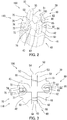
- FIG. 2 is a perspective view of an example of the end effector device 30.
- FIG 3 is a bottom view of the end effector device 30.
- the end effector device 30 includes a housing 40, a first gripper 100, and a second gripper 110.
- the housing 40 is formed in a substantially columnar shape around a central axis, and includes a peripheral side surface 41 and a bottom surface 42.
- the bottom surface 42 includes an opening 43.
- the opening 43 is formed in a cross shape so as to have two guide paths intersecting each other.
- the first gripper 100 includes a first finger 50 and a second finger 60 facing each other and configured to open and close.
- the second gripper 110 includes a third finger 70 and a fourth finger 80 facing each other and configured to open and close in a direction intersecting the first gripper 100.
- the first finger 50, the second finger 60, the third finger 70, and the fourth finger 80 each protrude from the opening 43.
- the first finger 50 and the second finger 60 are in substantially symmetric positions about the center axis of the housing 40 and move linearly so that the distance therebetween is increased or reduced in one of the guide paths of the opening 43.
- the housing 40 includes therewithin a first motor and a first drive mechanism not illustrated.
- the first drive mechanism includes for example a rack and a pinion for converting a rotational motion of the first motor into a linear motion.
- the first finger 50 and the second finger 60 are driven by the first drive mechanism.
- the third finger 70 and the fourth finger 80 are in substantially symmetric positions about the center axis of the housing 40 and move linearly so that the distance therebetween is increased or reduced in the other guide path of the opening 43.
- the housing 40 includes therewithin a second motor and a second drive mechanism not illustrated.
- the second drive mechanism includes for example a rack and a pinion for converting a rotational motion of the second motor into a linear motion.
- the third finger 70 and the fourth finger 80 are driven by the second drive mechanism independently of the first finger 50 and the second finger 60. Note that the first motor and the second motor may be replaced with a common motor.
- the length of the first finger 50 and the second finger 60 protruding from the opening 43 is substantially the same as the length of the third finger 70 and the fourth finger 80 protruding from the opening 43. Further, the maximum distance between the first finger 50 and the second finger 60 is substantially the same as the maximum distance between the third finger 70 and the fourth finger 80.
- the first finger 50 is formed in a rod shape having a rectangular cross section, and has a work contact surface 51, two side surfaces 52, a back surface 53, a sloping surface 54, and a top surface 55.
- the work contact surface 51 is formed in an elongated rectangular shape.
- Each of the side surfaces 52 is formed in an elongated pentagonal shape, and bounded by the work contact surface 51, the back surface 53, the sloping surface 54, and the top surface 55.
- the back surface 53 is formed in a rectangular shape smaller than the work contact surface 51, and bounded by the two side surfaces 52 and the sloping surface 54.
- the sloping surface 54 is bounded by the two side surfaces 52, the back surface 53, and the top surface 55.
- the top surface 55 is bounded by the work contact surface 51, the two side surfaces 52, and the sloping surface 54.
- the second finger 60 is formed symmetrically with the first finger 50, and has a work contact surface 61, two side surfaces 62, a back surface 63, a sloping surface 64, and a top surface 65.
- the third finger 70 is formed in an elongated hook shape and has a work contact surface 71, two side surfaces 72, a back surface 73, a sloping surface 74, and a facing surface 76.
- the work contact surface 71 is formed in a small rectangular shape.
- Each of the side surfaces 72 is formed in an arc shape, and bounded by the work contact surface 71, the back surface 73, the sloping surface 74, the top surface 75, and the facing surface 76.
- the back surface 73 is formed in a rectangular shape larger than the work contact surface 71, and bounded by the two side surfaces 72 and the sloping surface 74.
- the sloping surface 74 is bounded by the two side surfaces 72, the back surface 73, and the top surface 75.
- the top surface 75 is bounded by the work contact surface 71, the two side surfaces 72, and the sloping surface 74.
- the facing surface 76 is bounded by the work contact surface 71 and the two side surfaces 72.
- the fourth finger 80 is formed symmetrically with the third finger 70, and has a work contact surface 81, two side surfaces 82, a back surface 83, a sloping surface 84, a top surface 85, and a facing surface 86.
- the first gripper 100 including the first finger 50 and the second finger 60 can grip a type of work.
- the second gripper 110 including the third finger 70 and the fourth finger 80 can grip another type of work.
- the first gripper 100 and the second gripper 110 can be driven so as to simultaneously grip a common work.
- the work contact surface 51 of the first finger 50 and the work contact surface 61 of the second finger 60 may be made of material different from that of the work contact surface 71 of the third finger 70 and the work contact surface 81 of the fourth finger 80.
- a member made of a soft and flexible material may be attached to only the work contact surface 51 of the first finger 50 and the work contact surface 61 of the second finger 60 in order to prevent the work from being damaged or slipping.
- FIG. 4 is a perspective view illustrating a variation of the end effector device 30.
- the end effector device 30 illustrated in FIG 4 is different from the end effector device 30 illustrated in FIGS. 2 and 3 in that the length of the first finger 50 and the second finger 60 protruding from the opening 43 is longer than the length of the third finger 70 and the fourth finger 80 protruding from the opening 43.
- the end effector device 30 illustrated in FIG. 4 can be realized by replacing only the first finger 50 and the second finger 60 of the end effector device 30 illustrated in FIGS. 2 and 3 .
- the first gripper 100 and the second gripper 110 are selectively used depending on the shape of the work to be gripped.
- FIG. 5 is a perspective view illustrating another variation of the end effector device 30.
- the end effector device 30 illustrated in FIG. 5 is different from the end effector device 30 illustrated in FIG 4 in that the maximum distance between the first finger 50 and the second finger 60 is shorter than the maximum distance between the third finger 70 and the fourth finger 80.
- the end effector device 30 illustrated in FIG 5 can be realized by replacing only the third finger 70 and the fourth finger 80 of the end effector device 30 illustrated in FIG. 4 .
- the third finger 70 illustrated in FIG 5 is different from the third finger 70 illustrated in FIG 4 in that the third finger 70 in FIG 5 has greatly bent side surfaces 72 formed in an S-shape and an inwardly sloping surface 77 bounded by the side surfaces 72.
- the fourth finger 80 illustrated in FIG. 5 is different from the fourth finger 80 illustrated in FIG 4 in that the fourth finger 80 in FIG 5 has greatly bent side surfaces 82 formed in an S-shape and an inwardly sloping surface 87 bounded by the side surfaces 82.
- the fourth finger 80 illustrated in FIG. 5 is formed symmetrically with the third finger 70 illustrated in FIG. 5 .
- the height of the first finger 50 and the second finger 60 protruding from the opening 43 is substantially the same as the height of the third finger 70 and the fourth finger 80 protruding from the opening 43.
- the first gripper 100 and the second gripper 110 are selectively used depending on the dimensions of the work to be gripped.
- a low-cost end effector device 30 enabled to handle a variety of works is provided.
- the end effector device 30 includes the first gripper 100 and the second gripper 110 as illustrated in FIGS. 2 and 3 , but the elements of configuration are not limited thereto.
- the end effector device 30 may include another gripper in addition to the first gripper 100 and the second gripper 110. That is, the end effector device 30 may include three or more pairs of fingers.
Landscapes
- Engineering & Computer Science (AREA)
- Robotics (AREA)
- Mechanical Engineering (AREA)
- Health & Medical Sciences (AREA)
- General Health & Medical Sciences (AREA)
- Orthopedic Medicine & Surgery (AREA)
- Manipulator (AREA)
Abstract
Description
- The present disclosure relates to an end effector device and a robotic device.
- A robot hand device drives a finger mechanism with a single motor. The finger mechanism includes a base linkage member and a distal linkage member. A work is gripped by a pair of finger mechanisms.
- A known robotic device includes an end effector device and a robot hand device configured to drive the end effector device. The end effector device is exchangeably connected to a distal end of the robot hand device. An end effector device has two or three fingers to realize a work gripping function.
- An end effector device according to an aspect of the present disclosure includes a housing having an opening, a first gripper, and a second gripper. The first gripper includes a first finger and a second finger facing each other and configured to open and close. The second gripper includes a third finger and a fourth finger facing each other and configured to open and close in a direction intersecting the first gripper. The first finger, the second finger, the third finger, and the fourth finger each protrude from the opening.
- The robotic device according to the present disclosure includes the end effector device and a robot hand device configured to drive the end effector device.
-
-
FIG. 1 is a perspective view of an example of the robotic device according to an embodiment of the present disclosure. -
FIG. 2 is a perspective view of an example of the end effector device. -
FIG. 3 is a bottom view of the end effector device. -
FIG. 4 is a perspective view illustrating a variation of the end effector device. -
FIG. 5 is a perspective view illustrating another variation of the end effector device. - The following describes an embodiment of the present disclosure with reference to
FIGS. 1 to 5 . Elements which are the same or equivalent are labeled with the same reference signs in the drawings and description thereof is not repeated. - First, a
robotic device 10 according to the embodiment will be described with reference toFIG 1. FIG. 1 is a perspective view of an example of therobotic device 10 according to the embodiment. - As illustrated in
FIG. 1 , therobotic device 10 includes abase 20, arobot hand device 21, and anend effector device 30. - The
robot hand device 21 is disposed on thebase 20. Therobot hand device 21 has multiple axes to drive theend effector device 30. Theend effector device 30 is exchangeably connected to a distal end corresponding to a wrist of therobot hand device 21. - Next, the
end effector device 30 will be described with reference toFIGS. 1 ,2, and 3. FIG. 2 is a perspective view of an example of theend effector device 30.FIG 3 is a bottom view of theend effector device 30. - As illustrated in
FIGS. 2 and 3 , theend effector device 30 includes ahousing 40, afirst gripper 100, and asecond gripper 110. - The
housing 40 is formed in a substantially columnar shape around a central axis, and includes aperipheral side surface 41 and abottom surface 42. Thebottom surface 42 includes anopening 43. Theopening 43 is formed in a cross shape so as to have two guide paths intersecting each other. - The
first gripper 100 includes afirst finger 50 and asecond finger 60 facing each other and configured to open and close. Thesecond gripper 110 includes athird finger 70 and afourth finger 80 facing each other and configured to open and close in a direction intersecting thefirst gripper 100. Thefirst finger 50, thesecond finger 60, thethird finger 70, and thefourth finger 80 each protrude from theopening 43. - The
first finger 50 and thesecond finger 60 are in substantially symmetric positions about the center axis of thehousing 40 and move linearly so that the distance therebetween is increased or reduced in one of the guide paths of theopening 43. Thehousing 40 includes therewithin a first motor and a first drive mechanism not illustrated. The first drive mechanism includes for example a rack and a pinion for converting a rotational motion of the first motor into a linear motion. Thefirst finger 50 and thesecond finger 60 are driven by the first drive mechanism. - The
third finger 70 and thefourth finger 80 are in substantially symmetric positions about the center axis of thehousing 40 and move linearly so that the distance therebetween is increased or reduced in the other guide path of theopening 43. Thehousing 40 includes therewithin a second motor and a second drive mechanism not illustrated. The second drive mechanism includes for example a rack and a pinion for converting a rotational motion of the second motor into a linear motion. Thethird finger 70 and thefourth finger 80 are driven by the second drive mechanism independently of thefirst finger 50 and thesecond finger 60. Note that the first motor and the second motor may be replaced with a common motor. - In the
end effector device 30 illustrated inFIGS. 2 and 3 , the length of thefirst finger 50 and thesecond finger 60 protruding from theopening 43 is substantially the same as the length of thethird finger 70 and thefourth finger 80 protruding from theopening 43. Further, the maximum distance between thefirst finger 50 and thesecond finger 60 is substantially the same as the maximum distance between thethird finger 70 and thefourth finger 80. - The
first finger 50 is formed in a rod shape having a rectangular cross section, and has awork contact surface 51, twoside surfaces 52, aback surface 53, a slopingsurface 54, and atop surface 55. Thework contact surface 51 is formed in an elongated rectangular shape. Each of the side surfaces 52 is formed in an elongated pentagonal shape, and bounded by thework contact surface 51, theback surface 53, the slopingsurface 54, and thetop surface 55. Theback surface 53 is formed in a rectangular shape smaller than thework contact surface 51, and bounded by the twoside surfaces 52 and the slopingsurface 54. The slopingsurface 54 is bounded by the twoside surfaces 52, theback surface 53, and thetop surface 55. Thetop surface 55 is bounded by thework contact surface 51, the twoside surfaces 52, and the slopingsurface 54. - The
second finger 60 is formed symmetrically with thefirst finger 50, and has awork contact surface 61, twoside surfaces 62, aback surface 63, a slopingsurface 64, and atop surface 65. - The
third finger 70 is formed in an elongated hook shape and has awork contact surface 71, twoside surfaces 72, aback surface 73, a slopingsurface 74, and a facingsurface 76. Thework contact surface 71 is formed in a small rectangular shape. Each of the side surfaces 72 is formed in an arc shape, and bounded by thework contact surface 71, theback surface 73, the slopingsurface 74, thetop surface 75, and the facingsurface 76. Theback surface 73 is formed in a rectangular shape larger than thework contact surface 71, and bounded by the twoside surfaces 72 and the slopingsurface 74. The slopingsurface 74 is bounded by the twoside surfaces 72, theback surface 73, and thetop surface 75. Thetop surface 75 is bounded by thework contact surface 71, the twoside surfaces 72, and the slopingsurface 74. The facingsurface 76 is bounded by thework contact surface 71 and the two side surfaces 72. - The
fourth finger 80 is formed symmetrically with thethird finger 70, and has awork contact surface 81, twoside surfaces 82, aback surface 83, asloping surface 84, atop surface 85, and a facingsurface 86. - Using the
end effector device 30 illustrated inFIGS. 2 and 3 , thefirst gripper 100 including thefirst finger 50 and thesecond finger 60 can grip a type of work. In addition, thesecond gripper 110 including thethird finger 70 and thefourth finger 80 can grip another type of work. Further, thefirst gripper 100 and thesecond gripper 110 can be driven so as to simultaneously grip a common work. - The
work contact surface 51 of thefirst finger 50 and thework contact surface 61 of thesecond finger 60 may be made of material different from that of thework contact surface 71 of thethird finger 70 and thework contact surface 81 of thefourth finger 80. For example, a member made of a soft and flexible material may be attached to only thework contact surface 51 of thefirst finger 50 and thework contact surface 61 of thesecond finger 60 in order to prevent the work from being damaged or slipping. - Next, a variation of the
end effector device 30 will be described with reference toFIGS. 1 and4. FIG. 4 is a perspective view illustrating a variation of theend effector device 30. - The
end effector device 30 illustrated inFIG 4 is different from theend effector device 30 illustrated inFIGS. 2 and 3 in that the length of thefirst finger 50 and thesecond finger 60 protruding from theopening 43 is longer than the length of thethird finger 70 and thefourth finger 80 protruding from theopening 43. Theend effector device 30 illustrated inFIG. 4 can be realized by replacing only thefirst finger 50 and thesecond finger 60 of theend effector device 30 illustrated inFIGS. 2 and 3 . - In the
end effector device 30 illustrated inFIG 4 , thefirst gripper 100 and thesecond gripper 110 are selectively used depending on the shape of the work to be gripped. - Next, another variation of the
end effector device 30 will be described with reference toFIGS. 1 and5. FIG. 5 is a perspective view illustrating another variation of theend effector device 30. - The
end effector device 30 illustrated inFIG. 5 is different from theend effector device 30 illustrated inFIG 4 in that the maximum distance between thefirst finger 50 and thesecond finger 60 is shorter than the maximum distance between thethird finger 70 and thefourth finger 80. Theend effector device 30 illustrated inFIG 5 can be realized by replacing only thethird finger 70 and thefourth finger 80 of theend effector device 30 illustrated inFIG. 4 . - The
third finger 70 illustrated inFIG 5 is different from thethird finger 70 illustrated inFIG 4 in that thethird finger 70 inFIG 5 has greatly bent side surfaces 72 formed in an S-shape and an inwardly slopingsurface 77 bounded by the side surfaces 72. Thefourth finger 80 illustrated inFIG. 5 is different from thefourth finger 80 illustrated inFIG 4 in that thefourth finger 80 inFIG 5 has greatly bent side surfaces 82 formed in an S-shape and an inwardly slopingsurface 87 bounded by the side surfaces 82. - The
fourth finger 80 illustrated inFIG. 5 is formed symmetrically with thethird finger 70 illustrated inFIG. 5 . In theend effector device 30 illustrated inFIG. 5 , the height of thefirst finger 50 and thesecond finger 60 protruding from theopening 43 is substantially the same as the height of thethird finger 70 and thefourth finger 80 protruding from theopening 43. - In the
end effector device 30 illustrated inFIG 5 , thefirst gripper 100 and thesecond gripper 110 are selectively used depending on the dimensions of the work to be gripped. - According to the embodiment, a low-cost
end effector device 30 enabled to handle a variety of works is provided. - In the description of the embodiment described above, various technically preferable limitations may be given to illustrate a preferred embodiment in the present disclosure. However, the technical scope of the present disclosure is not limited to the embodiment unless otherwise specified by descriptions limiting the pre-sent disclosure. That is, the elements of configuration in the above-described embodiments can be appropriately replaced with existing constituent elements or the like, and various variations including combinations with other existing constituent elements are possible. The descriptions of the above embodiment should not be construed as limitations on the contents of the disclosure described in the scope of claims.
- For example, in the embodiment, the
end effector device 30 includes thefirst gripper 100 and thesecond gripper 110 as illustrated inFIGS. 2 and 3 , but the elements of configuration are not limited thereto. Theend effector device 30 may include another gripper in addition to thefirst gripper 100 and thesecond gripper 110. That is, theend effector device 30 may include three or more pairs of fingers.
Claims (6)
- An end effector device (30) comprising:a housing (40) having an opening (43);a first gripper (100); anda second gripper (110); whereinthe first gripper includes a first finger (50) and a second finger (60) facing each other and configured to open and close,the second gripper includes a third finger (70) and a fourth finger (80) facing each other and configured to open and close in a direction intersecting the first gripper, andthe first finger, the second finger, the third finger, and the fourth finger each protrude from the opening.
- The end effector device according to claim 1, wherein
a length of the first finger and the second finger protruding from the opening is longer than a length of the third finger and the fourth finger protruding from the opening. - The end effector device according to claim 1 or 2, wherein
a maximum distance between the first finger and the second finger is shorter than a maximum distance between the third finger and the fourth finger. - The end effector device according to any one of claims 1 to 3, wherein
the first finger, the second finger, the third finger, and the fourth finger each have a work contact surface, and material of the work contact surfaces of the first finger and the second finger is different from material of the work contact surfaces of the third finger and the fourth finger. - The end effector device according to any one of claims 1 to 4, wherein
the first gripper and the second gripper are driven so as to simultaneously grip a common work. - A robotic device (10) comprising:the end effector device according to any one of claims 1 to 5 anda robot hand device (21) configured to drive the end effector device.
Applications Claiming Priority (1)
| Application Number | Priority Date | Filing Date | Title |
|---|---|---|---|
| JP2019067487A JP7298245B2 (en) | 2019-03-29 | 2019-03-29 | End effector device and robot device |
Publications (2)
| Publication Number | Publication Date |
|---|---|
| EP3715068A1 true EP3715068A1 (en) | 2020-09-30 |
| EP3715068B1 EP3715068B1 (en) | 2025-04-30 |
Family
ID=69779973
Family Applications (1)
| Application Number | Title | Priority Date | Filing Date |
|---|---|---|---|
| EP20161405.4A Active EP3715068B1 (en) | 2019-03-29 | 2020-03-06 | End effector device and robotic device |
Country Status (4)
| Country | Link |
|---|---|
| US (1) | US11400603B2 (en) |
| EP (1) | EP3715068B1 (en) |
| JP (1) | JP7298245B2 (en) |
| CN (1) | CN111745669A (en) |
Families Citing this family (3)
| Publication number | Priority date | Publication date | Assignee | Title |
|---|---|---|---|---|
| US12012293B1 (en) * | 2019-08-20 | 2024-06-18 | Hallmark Cards, Incorporated | Systems and processes for selecting and packing articles |
| EP4197716B1 (en) * | 2021-12-15 | 2025-10-29 | Fameccanica.Data S.p.A. | An apparatus and a method for assembling kits of sanitary products |
| CN114939885B (en) * | 2022-06-06 | 2024-02-27 | 周鑫 | Rope-driven three-finger mechanical gripper and control method thereof |
Citations (5)
| Publication number | Priority date | Publication date | Assignee | Title |
|---|---|---|---|---|
| JPS5495453A (en) * | 1978-01-06 | 1979-07-27 | Hitachi Ltd | Holder |
| JP2010094804A (en) * | 2010-01-19 | 2010-04-30 | Taiyo Ltd | Motor-driven hand |
| US20120286536A1 (en) * | 2011-05-13 | 2012-11-15 | Seiko Epson Corporation | Robot hand and robot |
| CN106584494A (en) * | 2016-12-22 | 2017-04-26 | 六安力达生产力促进中心有限公司 | Self-centering Grabbing Mechanism for Manipulator |
| CN109483582A (en) * | 2018-11-30 | 2019-03-19 | 商丘师范学院 | A kind of forearm is equipped with the robot of mechanical arm assembly |
Family Cites Families (14)
| Publication number | Priority date | Publication date | Assignee | Title |
|---|---|---|---|---|
| JP2007118168A (en) | 2005-09-30 | 2007-05-17 | New-Era Co Ltd | Robot hand |
| JP5312207B2 (en) | 2009-06-05 | 2013-10-09 | 本田技研工業株式会社 | Robot hand device |
| US8439414B2 (en) * | 2009-10-20 | 2013-05-14 | Brooks Automation, Inc. | Gripper apparatus and method for containers of different sizes |
| JP5993539B2 (en) * | 2011-01-06 | 2016-09-14 | セイコーエプソン株式会社 | Robot hand and robot |
| JP5983080B2 (en) * | 2012-06-20 | 2016-08-31 | セイコーエプソン株式会社 | Robot hand, robot, and gripping mechanism |
| DE102013110216B4 (en) | 2013-09-17 | 2026-06-03 | Abb Schweiz Ag | End effector for a surgical instrument and surgical instrument with an end effector |
| JP2015085481A (en) * | 2013-11-01 | 2015-05-07 | セイコーエプソン株式会社 | Robot, robot system, robot controller and gripping method |
| US9554512B2 (en) * | 2014-09-12 | 2017-01-31 | Washington State University | Robotic systems, methods, and end-effectors for harvesting produce |
| JP2017100226A (en) * | 2015-12-01 | 2017-06-08 | 株式会社デンソー | Robot hand |
| CN105881529B (en) * | 2016-05-28 | 2017-11-10 | 深圳商巨智能设备股份有限公司 | A kind of mechanical arm assembly of industrial robot |
| JP6426685B2 (en) * | 2016-12-16 | 2018-11-21 | ファナック株式会社 | Grasping device attached to robot |
| WO2019031502A1 (en) * | 2017-08-10 | 2019-02-14 | Thk株式会社 | Hand mechanism and gripping system |
| CN107471234B (en) * | 2017-09-29 | 2018-05-15 | 安徽理工大学 | Foundry robot refers to asynchronous handgrip with omnidirectional more |
| CN108340390A (en) * | 2018-02-12 | 2018-07-31 | 哈尔滨三迪工控工程有限公司 | A kind of loading and unloading of hot-bending machine and glass inspecting manipuator |
-
2019
- 2019-03-29 JP JP2019067487A patent/JP7298245B2/en active Active
-
2020
- 2020-03-03 CN CN202010138605.2A patent/CN111745669A/en active Pending
- 2020-03-06 EP EP20161405.4A patent/EP3715068B1/en active Active
- 2020-03-06 US US16/811,838 patent/US11400603B2/en active Active
Patent Citations (5)
| Publication number | Priority date | Publication date | Assignee | Title |
|---|---|---|---|---|
| JPS5495453A (en) * | 1978-01-06 | 1979-07-27 | Hitachi Ltd | Holder |
| JP2010094804A (en) * | 2010-01-19 | 2010-04-30 | Taiyo Ltd | Motor-driven hand |
| US20120286536A1 (en) * | 2011-05-13 | 2012-11-15 | Seiko Epson Corporation | Robot hand and robot |
| CN106584494A (en) * | 2016-12-22 | 2017-04-26 | 六安力达生产力促进中心有限公司 | Self-centering Grabbing Mechanism for Manipulator |
| CN109483582A (en) * | 2018-11-30 | 2019-03-19 | 商丘师范学院 | A kind of forearm is equipped with the robot of mechanical arm assembly |
Also Published As
| Publication number | Publication date |
|---|---|
| CN111745669A (en) | 2020-10-09 |
| JP2020163532A (en) | 2020-10-08 |
| JP7298245B2 (en) | 2023-06-27 |
| US20200306992A1 (en) | 2020-10-01 |
| EP3715068B1 (en) | 2025-04-30 |
| US11400603B2 (en) | 2022-08-02 |
Similar Documents
| Publication | Publication Date | Title |
|---|---|---|
| CN103991082B (en) | Mechanical hand | |
| US11400603B2 (en) | End effector device and robotic device | |
| CN105563513B (en) | Flexible Adaptive Underactuated Robot Gripper | |
| US5947539A (en) | Apparatus and method having short linear motion for grasping objects | |
| US7950710B2 (en) | Robot | |
| US12384055B1 (en) | Multi-degree-of-freedom bionic dexterous hand | |
| JP2019107769A (en) | Flexible inferior driving holding device | |
| JP2011240422A (en) | Robot hand and robot | |
| JP2012236265A (en) | Robot hand, and robot | |
| CN119317525A (en) | Robot end effector and its robot finger | |
| CN107972051A (en) | Spacing leverage speedup compensating line puts down folder adaptive robot finger apparatus | |
| JP2006255805A (en) | Robot hand | |
| CN107984484A (en) | The accurate compensating line in end puts down folder adaptive robot finger apparatus | |
| CN106239551A (en) | Multi link two-man act part straight line flat folder adaptive robot finger apparatus | |
| JP4592794B2 (en) | Robot hand | |
| WO1982001153A1 (en) | Double hands | |
| CN207522618U (en) | The accurate compensating line in end puts down folder adaptive robot finger apparatus | |
| CN116945214A (en) | Robot finger device | |
| CN220741213U (en) | Clamp holder, mechanical arm and robot | |
| CN106272502B (en) | The flat folder adaptive robot finger apparatus of four bar four-wheel straight lines | |
| CN110774309A (en) | Single-drive three-finger mechanical gripper | |
| CN216830925U (en) | A grabbing manipulator device and a robot having the grabbing manipulator device | |
| JP7360623B2 (en) | robot hand | |
| JP2021088012A (en) | Hand device | |
| CN115179259B (en) | A flexible gripper with a single motor for grasping, pulling back and rigid positioning |
Legal Events
| Date | Code | Title | Description |
|---|---|---|---|
| PUAI | Public reference made under article 153(3) epc to a published international application that has entered the european phase |
Free format text: ORIGINAL CODE: 0009012 |
|
| STAA | Information on the status of an ep patent application or granted ep patent |
Free format text: STATUS: THE APPLICATION HAS BEEN PUBLISHED |
|
| AK | Designated contracting states |
Kind code of ref document: A1 Designated state(s): AL AT BE BG CH CY CZ DE DK EE ES FI FR GB GR HR HU IE IS IT LI LT LU LV MC MK MT NL NO PL PT RO RS SE SI SK SM TR |
|
| AX | Request for extension of the european patent |
Extension state: BA ME |
|
| STAA | Information on the status of an ep patent application or granted ep patent |
Free format text: STATUS: REQUEST FOR EXAMINATION WAS MADE |
|
| 17P | Request for examination filed |
Effective date: 20210323 |
|
| RBV | Designated contracting states (corrected) |
Designated state(s): AL AT BE BG CH CY CZ DE DK EE ES FI FR GB GR HR HU IE IS IT LI LT LU LV MC MK MT NL NO PL PT RO RS SE SI SK SM TR |
|
| STAA | Information on the status of an ep patent application or granted ep patent |
Free format text: STATUS: EXAMINATION IS IN PROGRESS |
|
| 17Q | First examination report despatched |
Effective date: 20210924 |
|
| P01 | Opt-out of the competence of the unified patent court (upc) registered |
Effective date: 20230420 |
|
| GRAP | Despatch of communication of intention to grant a patent |
Free format text: ORIGINAL CODE: EPIDOSNIGR1 |
|
| STAA | Information on the status of an ep patent application or granted ep patent |
Free format text: STATUS: GRANT OF PATENT IS INTENDED |
|
| INTG | Intention to grant announced |
Effective date: 20241217 |
|
| GRAS | Grant fee paid |
Free format text: ORIGINAL CODE: EPIDOSNIGR3 |
|
| GRAA | (expected) grant |
Free format text: ORIGINAL CODE: 0009210 |
|
| STAA | Information on the status of an ep patent application or granted ep patent |
Free format text: STATUS: THE PATENT HAS BEEN GRANTED |
|
| AK | Designated contracting states |
Kind code of ref document: B1 Designated state(s): AL AT BE BG CH CY CZ DE DK EE ES FI FR GB GR HR HU IE IS IT LI LT LU LV MC MK MT NL NO PL PT RO RS SE SI SK SM TR |
|
| REG | Reference to a national code |
Ref country code: CH Ref legal event code: EP Ref country code: GB Ref legal event code: FG4D |
|
| REG | Reference to a national code |
Ref country code: IE Ref legal event code: FG4D |
|
| REG | Reference to a national code |
Ref country code: DE Ref legal event code: R096 Ref document number: 602020050278 Country of ref document: DE |
|
| REG | Reference to a national code |
Ref country code: NL Ref legal event code: MP Effective date: 20250430 |
|
| REG | Reference to a national code |
Ref country code: AT Ref legal event code: MK05 Ref document number: 1789626 Country of ref document: AT Kind code of ref document: T Effective date: 20250430 |
|
| PG25 | Lapsed in a contracting state [announced via postgrant information from national office to epo] |
Ref country code: PT Free format text: LAPSE BECAUSE OF FAILURE TO SUBMIT A TRANSLATION OF THE DESCRIPTION OR TO PAY THE FEE WITHIN THE PRESCRIBED TIME-LIMIT Effective date: 20250901 Ref country code: FI Free format text: LAPSE BECAUSE OF FAILURE TO SUBMIT A TRANSLATION OF THE DESCRIPTION OR TO PAY THE FEE WITHIN THE PRESCRIBED TIME-LIMIT Effective date: 20250430 Ref country code: ES Free format text: LAPSE BECAUSE OF FAILURE TO SUBMIT A TRANSLATION OF THE DESCRIPTION OR TO PAY THE FEE WITHIN THE PRESCRIBED TIME-LIMIT Effective date: 20250430 |
|
| REG | Reference to a national code |
Ref country code: LT Ref legal event code: MG9D |
|
| PG25 | Lapsed in a contracting state [announced via postgrant information from national office to epo] |
Ref country code: NO Free format text: LAPSE BECAUSE OF FAILURE TO SUBMIT A TRANSLATION OF THE DESCRIPTION OR TO PAY THE FEE WITHIN THE PRESCRIBED TIME-LIMIT Effective date: 20250730 Ref country code: GR Free format text: LAPSE BECAUSE OF FAILURE TO SUBMIT A TRANSLATION OF THE DESCRIPTION OR TO PAY THE FEE WITHIN THE PRESCRIBED TIME-LIMIT Effective date: 20250731 |
|
| PG25 | Lapsed in a contracting state [announced via postgrant information from national office to epo] |
Ref country code: PL Free format text: LAPSE BECAUSE OF FAILURE TO SUBMIT A TRANSLATION OF THE DESCRIPTION OR TO PAY THE FEE WITHIN THE PRESCRIBED TIME-LIMIT Effective date: 20250430 Ref country code: NL Free format text: LAPSE BECAUSE OF FAILURE TO SUBMIT A TRANSLATION OF THE DESCRIPTION OR TO PAY THE FEE WITHIN THE PRESCRIBED TIME-LIMIT Effective date: 20250430 |
|
| PG25 | Lapsed in a contracting state [announced via postgrant information from national office to epo] |
Ref country code: BG Free format text: LAPSE BECAUSE OF FAILURE TO SUBMIT A TRANSLATION OF THE DESCRIPTION OR TO PAY THE FEE WITHIN THE PRESCRIBED TIME-LIMIT Effective date: 20250430 |
|
| PG25 | Lapsed in a contracting state [announced via postgrant information from national office to epo] |
Ref country code: HR Free format text: LAPSE BECAUSE OF FAILURE TO SUBMIT A TRANSLATION OF THE DESCRIPTION OR TO PAY THE FEE WITHIN THE PRESCRIBED TIME-LIMIT Effective date: 20250430 |
|
| PG25 | Lapsed in a contracting state [announced via postgrant information from national office to epo] |
Ref country code: AT Free format text: LAPSE BECAUSE OF FAILURE TO SUBMIT A TRANSLATION OF THE DESCRIPTION OR TO PAY THE FEE WITHIN THE PRESCRIBED TIME-LIMIT Effective date: 20250430 |
|
| PG25 | Lapsed in a contracting state [announced via postgrant information from national office to epo] |
Ref country code: RS Free format text: LAPSE BECAUSE OF FAILURE TO SUBMIT A TRANSLATION OF THE DESCRIPTION OR TO PAY THE FEE WITHIN THE PRESCRIBED TIME-LIMIT Effective date: 20250731 |
|
| PG25 | Lapsed in a contracting state [announced via postgrant information from national office to epo] |
Ref country code: IS Free format text: LAPSE BECAUSE OF FAILURE TO SUBMIT A TRANSLATION OF THE DESCRIPTION OR TO PAY THE FEE WITHIN THE PRESCRIBED TIME-LIMIT Effective date: 20250830 |
|
| PG25 | Lapsed in a contracting state [announced via postgrant information from national office to epo] |
Ref country code: LV Free format text: LAPSE BECAUSE OF FAILURE TO SUBMIT A TRANSLATION OF THE DESCRIPTION OR TO PAY THE FEE WITHIN THE PRESCRIBED TIME-LIMIT Effective date: 20250430 |
|
| PG25 | Lapsed in a contracting state [announced via postgrant information from national office to epo] |
Ref country code: DK Free format text: LAPSE BECAUSE OF FAILURE TO SUBMIT A TRANSLATION OF THE DESCRIPTION OR TO PAY THE FEE WITHIN THE PRESCRIBED TIME-LIMIT Effective date: 20250430 Ref country code: SM Free format text: LAPSE BECAUSE OF FAILURE TO SUBMIT A TRANSLATION OF THE DESCRIPTION OR TO PAY THE FEE WITHIN THE PRESCRIBED TIME-LIMIT Effective date: 20250430 |
|
| PG25 | Lapsed in a contracting state [announced via postgrant information from national office to epo] |
Ref country code: CZ Free format text: LAPSE BECAUSE OF FAILURE TO SUBMIT A TRANSLATION OF THE DESCRIPTION OR TO PAY THE FEE WITHIN THE PRESCRIBED TIME-LIMIT Effective date: 20250430 |
|
| PG25 | Lapsed in a contracting state [announced via postgrant information from national office to epo] |
Ref country code: EE Free format text: LAPSE BECAUSE OF FAILURE TO SUBMIT A TRANSLATION OF THE DESCRIPTION OR TO PAY THE FEE WITHIN THE PRESCRIBED TIME-LIMIT Effective date: 20250430 |
|
| PG25 | Lapsed in a contracting state [announced via postgrant information from national office to epo] |
Ref country code: SK Free format text: LAPSE BECAUSE OF FAILURE TO SUBMIT A TRANSLATION OF THE DESCRIPTION OR TO PAY THE FEE WITHIN THE PRESCRIBED TIME-LIMIT Effective date: 20250430 Ref country code: RO Free format text: LAPSE BECAUSE OF FAILURE TO SUBMIT A TRANSLATION OF THE DESCRIPTION OR TO PAY THE FEE WITHIN THE PRESCRIBED TIME-LIMIT Effective date: 20250430 |
|
| PG25 | Lapsed in a contracting state [announced via postgrant information from national office to epo] |
Ref country code: IT Free format text: LAPSE BECAUSE OF FAILURE TO SUBMIT A TRANSLATION OF THE DESCRIPTION OR TO PAY THE FEE WITHIN THE PRESCRIBED TIME-LIMIT Effective date: 20250430 |
|
| REG | Reference to a national code |
Ref country code: DE Ref legal event code: R097 Ref document number: 602020050278 Country of ref document: DE |
|
| PLBE | No opposition filed within time limit |
Free format text: ORIGINAL CODE: 0009261 |
|
| STAA | Information on the status of an ep patent application or granted ep patent |
Free format text: STATUS: NO OPPOSITION FILED WITHIN TIME LIMIT |
|
| REG | Reference to a national code |
Ref country code: CH Ref legal event code: L10 Free format text: ST27 STATUS EVENT CODE: U-0-0-L10-L00 (AS PROVIDED BY THE NATIONAL OFFICE) Effective date: 20260311 |
|
| 26N | No opposition filed |
Effective date: 20260202 |
|
| PGFP | Annual fee paid to national office [announced via postgrant information from national office to epo] |
Ref country code: GB Payment date: 20260220 Year of fee payment: 7 |
|
| PGFP | Annual fee paid to national office [announced via postgrant information from national office to epo] |
Ref country code: DE Payment date: 20260219 Year of fee payment: 7 |
|
| PGFP | Annual fee paid to national office [announced via postgrant information from national office to epo] |
Ref country code: FR Payment date: 20260219 Year of fee payment: 7 |
|
| PG25 | Lapsed in a contracting state [announced via postgrant information from national office to epo] |
Ref country code: LT Free format text: LAPSE BECAUSE OF FAILURE TO SUBMIT A TRANSLATION OF THE DESCRIPTION OR TO PAY THE FEE WITHIN THE PRESCRIBED TIME-LIMIT Effective date: 20250430 |
|
| PG25 | Lapsed in a contracting state [announced via postgrant information from national office to epo] |
Ref country code: SE Free format text: LAPSE BECAUSE OF FAILURE TO SUBMIT A TRANSLATION OF THE DESCRIPTION OR TO PAY THE FEE WITHIN THE PRESCRIBED TIME-LIMIT Effective date: 20250430 |