EP3714785B1 - Wearable apparatus and a method for calculating drift-free plantar pressure parameters for gait monitoring - Google Patents
Wearable apparatus and a method for calculating drift-free plantar pressure parameters for gait monitoring Download PDFInfo
- Publication number
- EP3714785B1 EP3714785B1 EP20164481.2A EP20164481A EP3714785B1 EP 3714785 B1 EP3714785 B1 EP 3714785B1 EP 20164481 A EP20164481 A EP 20164481A EP 3714785 B1 EP3714785 B1 EP 3714785B1
- Authority
- EP
- European Patent Office
- Prior art keywords
- values
- raw
- sub
- static pressure
- drift
- Prior art date
- Legal status (The legal status is an assumption and is not a legal conclusion. Google has not performed a legal analysis and makes no representation as to the accuracy of the status listed.)
- Active
Links
Images



Classifications
-
- A—HUMAN NECESSITIES
- A61—MEDICAL OR VETERINARY SCIENCE; HYGIENE
- A61B—DIAGNOSIS; SURGERY; IDENTIFICATION
- A61B5/00—Measuring for diagnostic purposes; Identification of persons
- A61B5/103—Measuring devices for testing the shape, pattern, colour, size or movement of the body or parts thereof, for diagnostic purposes
- A61B5/1036—Measuring load distribution, e.g. podologic studies
- A61B5/1038—Measuring plantar pressure during gait
-
- A—HUMAN NECESSITIES
- A61—MEDICAL OR VETERINARY SCIENCE; HYGIENE
- A61B—DIAGNOSIS; SURGERY; IDENTIFICATION
- A61B5/00—Measuring for diagnostic purposes; Identification of persons
- A61B5/103—Measuring devices for testing the shape, pattern, colour, size or movement of the body or parts thereof, for diagnostic purposes
- A61B5/11—Measuring movement of the entire body or parts thereof, e.g. head or hand tremor or mobility of a limb
- A61B5/112—Gait analysis
-
- A—HUMAN NECESSITIES
- A61—MEDICAL OR VETERINARY SCIENCE; HYGIENE
- A61B—DIAGNOSIS; SURGERY; IDENTIFICATION
- A61B5/00—Measuring for diagnostic purposes; Identification of persons
- A61B5/103—Measuring devices for testing the shape, pattern, colour, size or movement of the body or parts thereof, for diagnostic purposes
- A61B5/11—Measuring movement of the entire body or parts thereof, e.g. head or hand tremor or mobility of a limb
- A61B5/1121—Determining geometric values, e.g. centre of rotation or angular range of movement
- A61B5/1122—Determining geometric values, e.g. centre of rotation or angular range of movement of movement trajectories
-
- A—HUMAN NECESSITIES
- A61—MEDICAL OR VETERINARY SCIENCE; HYGIENE
- A61B—DIAGNOSIS; SURGERY; IDENTIFICATION
- A61B5/00—Measuring for diagnostic purposes; Identification of persons
- A61B5/68—Arrangements of detecting, measuring or recording means, e.g. sensors, in relation to patient
- A61B5/6801—Arrangements of detecting, measuring or recording means, e.g. sensors, in relation to patient specially adapted to be attached to or worn on the body surface
- A61B5/6802—Sensor mounted on worn items
- A61B5/6804—Garments; Clothes
- A61B5/6807—Footwear
-
- A—HUMAN NECESSITIES
- A61—MEDICAL OR VETERINARY SCIENCE; HYGIENE
- A61B—DIAGNOSIS; SURGERY; IDENTIFICATION
- A61B5/00—Measuring for diagnostic purposes; Identification of persons
- A61B5/68—Arrangements of detecting, measuring or recording means, e.g. sensors, in relation to patient
- A61B5/6801—Arrangements of detecting, measuring or recording means, e.g. sensors, in relation to patient specially adapted to be attached to or worn on the body surface
- A61B5/6843—Monitoring or controlling sensor contact pressure
-
- A—HUMAN NECESSITIES
- A61—MEDICAL OR VETERINARY SCIENCE; HYGIENE
- A61B—DIAGNOSIS; SURGERY; IDENTIFICATION
- A61B5/00—Measuring for diagnostic purposes; Identification of persons
- A61B5/72—Signal processing specially adapted for physiological signals or for diagnostic purposes
- A61B5/7203—Signal processing specially adapted for physiological signals or for diagnostic purposes for noise prevention, reduction or removal
- A61B5/7207—Signal processing specially adapted for physiological signals or for diagnostic purposes for noise prevention, reduction or removal of noise induced by motion artifacts
- A61B5/7214—Signal processing specially adapted for physiological signals or for diagnostic purposes for noise prevention, reduction or removal of noise induced by motion artifacts using signal cancellation, e.g. based on input of two identical physiological sensors spaced apart, or based on two signals derived from the same sensor, for different optical wavelengths
-
- A—HUMAN NECESSITIES
- A61—MEDICAL OR VETERINARY SCIENCE; HYGIENE
- A61B—DIAGNOSIS; SURGERY; IDENTIFICATION
- A61B5/00—Measuring for diagnostic purposes; Identification of persons
- A61B5/72—Signal processing specially adapted for physiological signals or for diagnostic purposes
- A61B5/7235—Details of waveform analysis
- A61B5/7246—Details of waveform analysis using correlation, e.g. template matching or determination of similarity
-
- A—HUMAN NECESSITIES
- A61—MEDICAL OR VETERINARY SCIENCE; HYGIENE
- A61B—DIAGNOSIS; SURGERY; IDENTIFICATION
- A61B5/00—Measuring for diagnostic purposes; Identification of persons
- A61B5/72—Signal processing specially adapted for physiological signals or for diagnostic purposes
- A61B5/7271—Specific aspects of physiological measurement analysis
- A61B5/7282—Event detection, e.g. detecting unique waveforms indicative of a medical condition
-
- G—PHYSICS
- G01—MEASURING; TESTING
- G01C—MEASURING DISTANCES, LEVELS OR BEARINGS; SURVEYING; NAVIGATION; GYROSCOPIC INSTRUMENTS; PHOTOGRAMMETRY OR VIDEOGRAMMETRY
- G01C19/00—Gyroscopes; Turn-sensitive devices using vibrating masses; Turn-sensitive devices without moving masses; Measuring angular rate using gyroscopic effects
-
- G—PHYSICS
- G01—MEASURING; TESTING
- G01L—MEASURING FORCE, STRESS, TORQUE, WORK, MECHANICAL POWER, MECHANICAL EFFICIENCY, OR FLUID PRESSURE
- G01L1/00—Measuring force or stress, in general
- G01L1/16—Measuring force or stress, in general using properties of piezoelectric devices
-
- G—PHYSICS
- G01—MEASURING; TESTING
- G01P—MEASURING LINEAR OR ANGULAR SPEED, ACCELERATION, DECELERATION, OR SHOCK; INDICATING PRESENCE, ABSENCE, OR DIRECTION, OF MOVEMENT
- G01P15/00—Measuring acceleration; Measuring deceleration; Measuring shock, i.e. sudden change of acceleration
- G01P15/02—Measuring acceleration; Measuring deceleration; Measuring shock, i.e. sudden change of acceleration by making use of inertia forces using solid seismic masses
-
- G—PHYSICS
- G01—MEASURING; TESTING
- G01P—MEASURING LINEAR OR ANGULAR SPEED, ACCELERATION, DECELERATION, OR SHOCK; INDICATING PRESENCE, ABSENCE, OR DIRECTION, OF MOVEMENT
- G01P15/00—Measuring acceleration; Measuring deceleration; Measuring shock, i.e. sudden change of acceleration
- G01P15/18—Measuring acceleration; Measuring deceleration; Measuring shock, i.e. sudden change of acceleration in two or more dimensions
-
- G—PHYSICS
- G01—MEASURING; TESTING
- G01P—MEASURING LINEAR OR ANGULAR SPEED, ACCELERATION, DECELERATION, OR SHOCK; INDICATING PRESENCE, ABSENCE, OR DIRECTION, OF MOVEMENT
- G01P7/00—Measuring speed by integrating acceleration
-
- A—HUMAN NECESSITIES
- A61—MEDICAL OR VETERINARY SCIENCE; HYGIENE
- A61B—DIAGNOSIS; SURGERY; IDENTIFICATION
- A61B2562/00—Details of sensors; Constructional details of sensor housings or probes; Accessories for sensors
- A61B2562/02—Details of sensors specially adapted for in-vivo measurements
- A61B2562/0219—Inertial sensors, e.g. accelerometers, gyroscopes, tilt switches
-
- A—HUMAN NECESSITIES
- A61—MEDICAL OR VETERINARY SCIENCE; HYGIENE
- A61B—DIAGNOSIS; SURGERY; IDENTIFICATION
- A61B2562/00—Details of sensors; Constructional details of sensor housings or probes; Accessories for sensors
- A61B2562/02—Details of sensors specially adapted for in-vivo measurements
- A61B2562/0247—Pressure sensors
Definitions
- the disclosure herein generally relates to healthcare and maintenance of an individual, and particularly to wearable apparatus and a method for calculating drift-free plantar pressure parameters for gait monitoring using off-the shelf piezoelectric sensors.
- Plantar pressure parameters of the individual play vital role for analyzing the walking patterns which further helps in evaluating Parkinsonian gait, mobility and walking disorders of the individual. Also, the plantar pressure parameters are helpful in evaluating running performance of an athlete.
- Conventional techniques employ wide variety of sensors for acquiring inputs indicating pressure values of the individual, while moving, to calculate the plantar pressure parameters.
- US 2017/055880 A1 discloses a quantitative gait training and/or analysis system, which includes a pair of footwear modules that may include a shank module and an independent processing module. Each footwear module may have a sole portion, a heel portion, a speaker, vibrotactile transducer and a wireless communication module. Sensors may permit the extraction of gait kinematics in real time and provide feedback from it. Embodiments may store data for later reduction and analysis. Embodiments employing calibration-based estimation of kinematic gait parameters are described.
- the invention is defined by a wearable apparatus according to claim 1, and a processor implemented method according to claim 4. Further embodiments are defined by dependent claims 2, 3, 5-9.
- Piezoelectric sensors are widely used in many applications as they may easily detect jerks, touches or finger-taps thereby providing an instantaneous and ultra-short duration response. But, the piezoelectric sensors may not directly provide an accurate continuous static pressure measurement especially for long durations for example more than an hour. Hence the provided continuous static pressure measurement for long durations may result in an error which is termed as a drift.
- the technical problem of the drift that appears when pressure measurements are taken for long durations is addressed by a wearable apparatus and a method for calculating drift-free plantar pressure parameters for gait monitoring which provides a cost-effective solution to calculate drift-free plantar pressure parameters of an individual.
- Drift-free static pressure data is obtained by numerically integrating the acquired dynamic sensor data from the piezoelectric sensors placed within a sole of a footwear at different positions representing pressure points of a foot of the individual, using a Linear Temporal Cumulated Error Model ( LiTCEM ) correction mechanism.
- LiTCEM Linear Temporal Cumulated Error Model
- An Inertial Measurement Unit (IMU sensor) is used for isolating a zero-pressure duration in the acquired dynamic sensor data to prevent the drift, wherein the zero-pressure duration is indicative of the foot of the individual being in air during a stride.
- FIG.1A through FIG.5 where similar reference characters denote corresponding features consistently throughout the figures, there are shown preferred embodiments and these embodiments are described in the context of the following exemplary wearable apparatus and the method for calculating drift-free plantar pressure parameters for gait monitoring.
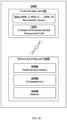
- FIG. 1A is a functional block diagram of a wearable apparatus 100A for calculating drift-free plantar pressure parameters for gait monitoring, in accordance with an embodiment of the present disclosure.
- the wearable apparatus 100A comprising a footwear input unit 102 and a processing unit 104A.
- the footwear input unit 102 comprises a plurality of piezoelectric sensors 102a (102a_1, 102a _2..., 102a_ N ) and a 6-Degree Of Freedom (DOF) Inertial Measurement Unit (IMU) 102b.
- DOF 6-Degree Of Freedom
- IMU Inertial Measurement Unit
- the processing unit 104A comprises one or more processors 104A1, communication interface device(s) or input/output (I/O) interface(s) 104A2, and one or more data storage devices or memory 104A3 operatively coupled to the one or more processors 104A1.
- the wearable apparatus 100A may be an in-sole based footwear including a shoe, a sandal and a like.
- the plurality of piezoelectric sensors 102a (102a_1, 102a_2..., 102a_ N ) are off-the shelf piezoelectric sensors generally available in the market.
- FIG.1B is a block diagram of a wearable system 100B for calculating drift-free plantar pressure parameters for gait monitoring, in accordance with another embodiment of the present disclosure.
- the wearable system 100B comprising a footwear input unit 102 and a remote processing unit 104B.
- the footwear input unit 102 comprises a plurality of piezoelectric sensors 102a (102a_1, 102a_2..., 102a_ N ) and a 6-Degree Of Freedom (DOF) Inertial Measurement Unit (IMU) 102b.
- DOF 6-Degree Of Freedom
- IMU Inertial Measurement Unit
- the remote processing unit 104B comprises one or more processors 104B1, communication interface device(s) or input/output (I/O) interface(s) 104B2, and one or more data storage devices or memory 104B3 operatively coupled to the one or more processors 104B1.
- the footwear input unit 102 may be present in an in-sole based footwear including a shoe, a sandal and a like.
- the plurality of piezoelectric sensors 102a (102a_1, 102a_2..., 102a_ N ) are off-the shelf piezoelectric sensors generally available in the market.
- the remote processing unit 104B can be implemented in a variety of computing systems, such as laptop computers, notebooks, hand-held devices, workstations, mainframe computers, servers, a network cloud and the like.
- the remote processing unit 104B is in communication with the footwear input unit 102 either via a physical connection or with a wireless connection through the communication interface device(s) or input/output (I/O) interface(s) 104B2.
- the one or more processors 104A1 of FIG.1A and 104B1 of FIG.1B may be one or more software processing modules or hardware processors and can be implemented as one or more microprocessors, microcomputers, microcontrollers, digital signal processors, central processing units, state machines, graphics controllers, logic circuitries, and/or any devices that manipulate signals based on operational instructions.
- the processor(s) is configured to fetch and execute computer-readable instructions stored in the memory.
- the I/O interface device(s) 104A2 of FIG. 1A and 104B2 of FIG. 1B can include a variety of software and hardware interfaces, for example, a web interface, a graphical user interface, and the like and can facilitate multiple communications within a wide variety of networks N/W and protocol types, including wired networks, for example, LAN, cable, etc., and wireless networks, such as WLAN, cellular, or satellite.
- the I/O interface device(s) can include one or more ports for connecting a number of devices to one another or to another server.
- the memory 104A3 of FIG. 1A and 104B3 of FIG.1B may include any computer-readable medium known in the art including, for example, volatile memory, such as static random access memory (SRAM) and dynamic random access memory (DRAM), and/or non-volatile memory, such as read only memory (ROM), erasable programmable ROM, flash memories, hard disks, optical disks, and magnetic tapes.
- volatile memory such as static random access memory (SRAM) and dynamic random access memory (DRAM)
- non-volatile memory such as read only memory (ROM), erasable programmable ROM, flash memories, hard disks, optical disks, and magnetic tapes.
- functional aspects and capabilities of components such as the one or more processors (104A1 and 104B1), the communication interface device(s) or input/output (I/O) interface(s) (104A2 and 104B2), and the one or more data storage devices or memory (104A3 and 104B3), of the embodiments illustrated in FIG.1A and FIG.1B are the same. But the only difference between the embodiments of FIG.1A and FIG.1B is that the processing unit 104A of FIG. 1A is part of the footwear whereas the remote processing unit 104B of FIG.IB is remote to the footwear, the footwear input unit (102), the processing unit (104A) and the remote processing unit (104B), all being wearable devices.
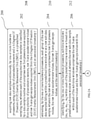
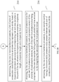
- FIG.2A through FIG.2C illustrates a flow diagram of a processor implemented method 200 for calculating drift-free plantar pressure parameters for gait monitoring, in accordance with an embodiment of the present disclosure.
- the steps of the method 200 will now be explained in detail with reference to the wearable apparatus 100A of FIG.1A and the wearable system 100B of FIG.1B .
- process steps, method steps, techniques or the like may be described in a sequential order, such processes, methods and techniques may be configured to work in alternate orders. In other words, any sequence or order of steps that may be described does not necessarily indicate a requirement that the steps be performed in that order.
- the steps of processes described herein may be performed in any order practical. Further, some steps may be performed simultaneously.
- raw data samples are acquired continuously at a predefined sampling rate, using a plurality of piezoelectric sensors (102a (102a_1, 102a_2..., 102a_ N ) of FIG.1A and FIG.1B ) and a 6-Degree Of Freedom (DOF) Inertial Measurement Unit (IMU) (102b of FIG.1A and FIG.1B ).
- piezoelectric sensors 102a (102a_1, 102a_2..., 102a_ N ) of FIG.1A and FIG.1B
- DOF 6-Degree Of Freedom
- IMU Inertial Measurement Unit
- five piezoelectric sensors are sufficient to acquire the raw data samples for calculating effective drift-free plantar pressure parameters of the individual.
- the plurality of piezoelectric sensors (102a (102a_1, 102a_2..., 102a_ N ) of FIG.1A and FIG.1B ) are placed within a sole of a footwear at different positions representing pressure points of a foot of the individual.
- the five typical pressure points are interphalangeal joint, metatarsophalangeal joint, heel, lateral calcaneus and distal Metatarsophalangeal joint.
- the 6-Degree Of Freedom (DOF) Inertial Measurement Unit (IMU) (102b of FIG.1A and FIG.1B ) is placed at bottom of the footwear representing mid foot area of the individual.
- DOF 6-Degree Of Freedom
- IMU Inertial Measurement Unit
- raw data samples are acquired continuously at the predefined sampling rate even when the footwear is not being worn by the individual.
- the predefined sampling rate may be 100 Hertz (100 samples per second).
- the footwear may be an in-sole based footwear including a shoe, a sandal and the like.
- Each of the acquired raw data samples is identified by a data sample number.
- Each of the acquired raw data samples comprises raw foot pressure values acquired from the plurality of piezoelectric sensors (102a (102a_1, 102a_2..., 102a_ N ) of FIG.1A and FIG.1B ), raw 3-axis accelerometer values and raw 3-axis gyroscope values acquired from the 6-Degree Of Freedom (DOF) Inertial Measurement Unit (IMU) (102b of FIG.1A and FIG.1B ), and an associated timestamp t.
- the raw foot pressure values represent electric voltage values that are generated due to change in mechanical stress or forces applied along a vertical plane, while walking, standing, moving or running by the individual.
- the raw 3-axis accelerometer values represent acceleration values along X-axis, Y-axis and Z-axis that are generated due to the acceleration forces while walking, standing, moving or running by the individual.
- the acceleration values comprise linear acceleration values and acceleration components due to a gravity.
- the raw 3-axis gyroscope values represent angular speed values along X-axis, Y-axis and Z-axis defining an orientation of the individual while walking, standing, moving or running.
- each of the acquired raw data samples may be represented in a following format: S j t j P 1 jr , P 2 jr , P 3 jr , ... P Njr A Xjr A Yjr A Zjr G Xjr , G Yjr , G Zjr wherein j represents a data sample number, S j represents a raw data sample for the data sample number j , ( P 1 jr , P 2 jr , P 3 jr , ...
- P Njr represents raw foot pressure values of each piezoelectric sensor of the N piezoelectric sensors (102a (102a_1, 102a_2..., 102a_ N ) of FIG.1A and FIG.1B ) for the data sample number j
- ( A Xjr , A Yjr , A Zjr ) represents the raw 3-axis accelerometer values along X-axis, Y- axis and Z-axis
- G Xjr , G Yjr , G Zjr represents the raw 3-axis gyroscope values along X-axis, Y-axis and Z-axis
- r denotes that each value in the data sample is raw and t j represents a timestamp for the data sample number j.
- the one or more hardware processors 104A1 of FIG.1A and 104B1 of FIG.1B are configured to extract, at step 204, each group of the raw data samples falling within a predefined time window w as a raw sub-data sample.
- the raw sub-data sample comprises the raw foot pressure values, the raw 3-axis accelerometer values, the raw 3-axis gyroscope values, and the associated timestamp t.
- the predefined time window w may be 160 seconds.
- each raw sub-data sample comprises 16,000 number of samples when the predefined time window w is 160 seconds and the predefined sampling rate is 100 Hertz.
- the one or more hardware processors 104A1 of FIG.1A and 104B1 of FIG.IB are configured to receive each raw data sample acquired using the plurality of piezoelectric sensors (102a (102a_1, 102a_2..., 102a_ N ) of FIG.1A and FIG.1B ) and the 6-Degree Of Freedom (DOF) Inertial Measurement Unit (IMU) (102b of FIG.1A and FIG.1B ), before extracting each group of the raw data samples falling within a predefined time window w as a raw sub-data sample.
- DOE 6-Degree Of Freedom
- IMU Inertial Measurement Unit
- the one or more hardware processors 104A1 of FIG.1A and 104B1 of FIG.1B are configured to identify, at step 206, sub-time windows ( m 1 , m 2 , m 3 ... , m n ) within each of the predefined time window w, based on a predefined sub-time window duration d .
- the raw sub-data sample within each of the sub-time windows comprises the raw 3-axis accelerometer values and the raw 3-axis gyroscope values with the associated timestamp t.
- the predefined sub-time window duration d may be 0.5 seconds.
- each of the sub-time windows comprises 50 number of raw sub-data samples, when the predefined time window w is 160 seconds, the predefined sampling rate is 100 Hertz and the predefined sub-time window duration d is 0.5 seconds.
- each of the predefined time window w comprises 320 number of sub-time windows ( m 1 , m 2 , m 3 ... , m n ).
- the one or more hardware processors 104A1 of FIG.1A and 104B1 of FIG.1B are configured to determine, at step 208, a list of pairs of consecutive identified sub-time windows that represent a true stride, based on trajectory parameters associated with corresponding raw sub-data samples in the pairs of the list.
- the trajectory parameters comprise a trajectory length, a trajectory height and a trajectory foot roll.
- a standard deviation value for each sub-time window ( m 1 , m 2 , m 3 ...,m n ), is calculated based on associated raw 3-axis accelerometer values comprised in the associated sub-time window.
- a sub-list of the sub-time windows whose standard deviation values less than a predefined threshold is identified.
- a 3-dimensional trajectory for each pair of consecutive identified sub-time windows in the sub-list is calculated, based on the associated raw 3-axis accelerometer values and the associated raw 3-axis gyroscope values.
- the trajectory parameters for each pair of the consecutive identified sub-time windows in the sub-list are determined based on an associated 3-dimensional trajectory.
- the list of pairs of consecutive identified sub-time windows that represent the true stride are determined based on the associated determined trajectory parameters satisfying: (i) associated determined trajectory length ranges between predefined upper and lower trajectory length threshold limits; (ii) associated determined trajectory height ranges between predefined upper and lower trajectory height threshold limits; and (iii) associated determined trajectory foot roll is less than a predefined trajectory foot threshold limit.
- the 3-dimensional trajectory for each pair of consecutive identified sub-time windows is determined by removing gravity from the raw 3-axis accelerometer values using the associated raw 3-axis gyroscope values to obtain linear acceleration values.
- the raw 3-axis accelerometer values may vary from actual accelerometer values due to various factors including internal vibrations, manufacturing bias, temperature changes, cross axes interference etc. This trend of error defining the difference between the actual accelerometer values and the raw 3-axis accelerometer values, is termed as drift.
- drift When performing a numerical integration to determine the velocity values, the drift goes up and net drift rate may be intensified in subsequent calculations.
- a Linear Temporal Cumulated Error Model ( LiTCEM ) correction method is applied on the linear acceleration values to obtain corrected acceleration values for resolving the drift.
- the LiTCEM correction method is a form of zero correction mechanism which works on a single data section at a time.
- the single data section is chosen in such a way that the starting and ending values in the single data section should be zero.
- the LiTCEM correction method is performed on the single data section comprising a plurality of values as follows: (i) a first value in the single data section is subtracted from the plurality of values present in the single data section; (ii) a last value present in the resultant single data section represents a cumulated error which is then subtracted from plurality of values present in the resultant single data section linearly with time to obtain error-free single data section comprising corrected plurality of values.
- the first linear acceleration value is subtracted from the linear acceleration values of the data section to obtain the revised data section with the linear acceleration values, then the last linear acceleration value present in the revised data section is subtracted from the linear acceleration values of the revised data section, linearly with time to obtain corrected linear acceleration values.
- the corrected linear acceleration values are numerically integrated over time to determine velocity values.
- the data section of the linear acceleration values represents the linear acceleration values present in associated pair of consecutive identified sub-time windows.
- the LiTCEM correction method is applied on the determined velocity values to obtain corrected velocity values.
- the first velocity value is subtracted from the determined velocity values of the data section to obtain the revised data section with the velocity values, then the last velocity value present in the revised data section is subtracted from the velocity values of the revised data section, linearly with time to obtain corrected velocity values.
- the obtained corrected velocity values are integrated over time to calculate the 3-dimensional trajectory for the associated pair of consecutive identified sub-time windows.
- the trajectory length is determined as a Euclidean distance between a start point and an end point of the associated 3-dimensional trajectory.
- the trajectory height is defined as a maximum distance between the ground and the foot during the stride.
- the trajectory foot roll represents an angle of rotation of the foot during traversing the trajectory about a vertical direction (direction opposite to gravity).
- the angle of rotation of the foot is determined by numerically integrating the raw gyroscope values representing the angular speed values along the vertical direction using trapezoidal integration.
- the one or more hardware processors 104A1 of FIG.1A and 104B1 of FIG.1B are configured to obtain, at step 210, a static pressure value for each raw foot pressure value acquired by each piezoelectric sensor of the plurality of piezoelectric sensors (102a (102a_1, 102a_2..., 102a_ N ) of FIG.1A and FIG.1B ), by integrating the associated raw foot pressure values over time.
- Each of the raw foot pressure value being comprised in the raw data samples falling within each predefined time window w.
- the static pressure value for each raw foot pressure value may comprises the drift due to the integration of the associated raw foot pressure values over time, which has to be removed.
- the one or more hardware processors 104A1 of FIG.1A and 104B1 of FIG.1B are configured to extract, at step 212, a data sample number having a minimum static pressure value present between each pair of consecutive identified sub-time windows that represent the true stride.
- the minimum static pressure value present between each pair of consecutive identified sub-time windows that represent the true stride is supposed to be zero representing a zero pressure duration, when the foot of the individual is in the air. But due to the drift resulted while obtaining the static pressure value by integrating the associated raw foot pressure values, the zero pressure duration is not observed, which has to be corrected.
- the one or more hardware processors 104A1 of FIG.1A and 104B1 of FIG.1B are configured to calculate, at step 214, drift-free static pressure values ( PC ij ) for each raw foot pressure value of each piezoelectric sensor of the plurality of piezoelectric sensors (102a (102a_1, 102a_2..., 102a_ N ) of FIG.1A and FIG.1B ), comprised in the raw data samples falling within each predefined time window w, using the Linear Temporal Cumulated Error Model ( LiTCEM ) correction method.
- the LiTCEM correction method is applied on associated static pressure values comprised between each pair of consecutive data sample numbers having the minimum static pressure value, to calculate the drift-free static pressure values ( PC ij ).
- the first static pressure value is subtracted from the obtained static pressure values of the data section to obtain the revised data section with the static pressure values, then the last static pressure value present in the revised data section is subtracted from the static pressure values of the revised data section, linearly with time to obtain the drift-free static pressure values ( PC ij ).
- the one or more hardware processors 104A1 of FIG.1A and 104B1 of FIG.1B are configured to calculate, at step 216, drift-free plantar pressure parameters in terms of a drift-free Vertical Ground Reaction Force (VGRF ) and a 2-dimensional Centre of Pressure ( CoP ) location for each data sample number falling within each predefined time window w.
- the drift-free plantar pressure parameters are measured for each raw data sample along with the associated timestamp t.
- the drift-free Vertical Ground Reaction Force (VGRF ) is calculated by adding drift-free static pressure values of the plurality of piezoelectric sensors (102a (102a_1, 102a_2..., 102a_ N ) of FIG.1A and FIG.1B ) associated with the data sample number.
- the 2-dimensional Centre of Pressure ( CoP ) location is calculated based on associated drift-free static pressure values, associated drift-free Vertical Ground Reaction Force (VGRF ) and locations of associated piezoelectric sensors.
- the locations of associated piezoelectric sensors are the physical locations where the associated piezoelectric sensors placed in the sole of the footwear, representing pressure points of the foot including interphalangeal joint, metatarsophalangeal joint, heel, lateral calcaneus and distal Metatarsophalangeal joint.
- VGRF Vertical Ground Reaction Force
- FIG.3 is a perspective view of a 3-dimensional trajectory of a true stride calculated between a pair of consecutive identified sub-time windows, in accordance with an embodiment of the present disclosure.
- the trajectory parameters comprising the trajectory length, the trajectory height and the trajectory foot roll are determined based on the 3-dimensional trajectory for the associated pair of consecutive identified sub-time windows.
- the trajectory length is determined as the Euclidean distance between the start point and the end point of the associated 3-dimensional trajectory.
- trajectory height max r i for all 1 ⁇ i ⁇ n
- FIG.4 is a graph showing vertical ground reaction force calculated from static pressure values having a drift for data samples falling within a time window of 160 seconds, in accordance with an embodiment of the present disclosure.
- FIG.5 is a graph showing drift-free vertical ground reaction force calculated from drift-free static pressure values for data samples falling within a time window of 160 seconds, in accordance with an embodiment of the present disclosure.
- the zero-pressure duration is present to show the drift-free static pressure values as zero which is indicative of the foot of the individual being in the air during the stride, resulting in vertical ground reaction force (VGRF) zero, but due to the drift in static pressure values, the vertical ground reaction force (VGRF) is instead non zero and gradually increasing as depicting in FIG.4 which is inaccurate and normally not possible.
- the drift-free plantar pressure parameters are stored in the memory 104A3 of FIG.1A and 104B3 of FIG.1B .
- the stored drift-free plantar pressure parameters are helpful for analyzing walking patterns which further helps in monitoring gait of the individual.
- the gait monitoring includes evaluating Parkinsonian gait, mobility and walking disorders of the individual.
- the drift-free plantar pressure parameters are helpful in evaluating running performance of an athlete.
- the individual may be a healthy person, a person with walking disorders or an athlete.
- the wearable apparatus 100A and the wearable system 100B of the present disclosure calculates the drift-free plantar pressure parameters of living beings, in general for gait monitoring, wherein the living beings may include animals.
- the remote processing unit 104B of FIG.1B may be a desktop or a portable electronic device including a mobile phone, a smart phone, hand-held device or a Personal Digital Assistant (PDA).
- PDA Personal Digital Assistant
- drift-free plantar pressure parameters are calculated using the drift-free static pressure data which is obtained by numerically integrating the acquired dynamic sensor data from the piezoelectric sensors, using the LiTCEM correction mechanism.
- the 6-DOF Inertial Measurement Unit helps in isolating the zero-pressure duration which is indicative of foot of the individual being in the air during the stride, while obtaining drift-free static pressure data.
- the disclosed wearable apparatus is very less expensive compare to the existing wearable devices, as off-the shelf piezoelectric sensors are used which are generally available in the market.
- the disclosed wearable apparatus and the wearable system calculate the drift-free plantar pressure parameters for long durations and hence is very helpful in monitoring the walking patterns of the individual for long durations effectively.
- the disclosed wearable apparatus and the wearable system also calculate the drift-free kinematic parameters such as the trajectory length, the trajectory height and the trajectory foot roll which are helpful in analysing walking speed, angular velocity and so on of the individual.
- the disclosed wearable apparatus is easily wearable and flexible.
- the hardware device can be any kind of device which can be programmed including e.g. any kind of computer like a server or a personal computer, or the like, or any combination thereof.
- the device may also include means which could be e.g. hardware means like e.g. an application-specific integrated circuit (ASIC), a field-programmable gate array (FPGA), or a combination of hardware and software means, e.g.
- ASIC application-specific integrated circuit
- FPGA field-programmable gate array
- the means can include both hardware means and software means.
- the method embodiments described herein could be implemented in hardware and software.
- the device may also include software means.
- the embodiments may be implemented on different hardware devices, e.g. using a plurality of CPUs.
- the embodiments herein can comprise hardware and software elements.
- the embodiments that are implemented in software include but are not limited to, firmware, resident software, microcode, etc.
- the functions performed by the one or more processors described herein after may be implemented in one or more modules.
- a computer-readable storage medium refers to any type of physical memory on which information or data readable by a processor may be stored.
- a computer-readable storage medium may store instructions for execution by one or more processors, including instructions for causing the processor(s) to perform steps or stages consistent with the embodiments described herein.
- the term "computer-readable medium” should be understood to include tangible items and exclude carrier waves and transient signals, i.e., be non-transitory. Examples include random access memory (RAM), read-only memory (ROM), volatile memory, nonvolatile memory, hard drives, CD ROMs, DVDs, flash drives, disks, and any other known physical storage media.
Landscapes
- Health & Medical Sciences (AREA)
- Life Sciences & Earth Sciences (AREA)
- Physics & Mathematics (AREA)
- Engineering & Computer Science (AREA)
- General Health & Medical Sciences (AREA)
- Biomedical Technology (AREA)
- Heart & Thoracic Surgery (AREA)
- Medical Informatics (AREA)
- Molecular Biology (AREA)
- Surgery (AREA)
- Animal Behavior & Ethology (AREA)
- Biophysics (AREA)
- Public Health (AREA)
- Veterinary Medicine (AREA)
- Pathology (AREA)
- General Physics & Mathematics (AREA)
- Physiology (AREA)
- Signal Processing (AREA)
- Dentistry (AREA)
- Oral & Maxillofacial Surgery (AREA)
- Computer Vision & Pattern Recognition (AREA)
- Psychiatry (AREA)
- Artificial Intelligence (AREA)
- Radar, Positioning & Navigation (AREA)
- Remote Sensing (AREA)
- Geometry (AREA)
- Measurement Of The Respiration, Hearing Ability, Form, And Blood Characteristics Of Living Organisms (AREA)
Description
- The present application claims priority from:
Indian Patent Application No. 201921011810, filed on 26 March, 2019 - The disclosure herein generally relates to healthcare and maintenance of an individual, and particularly to wearable apparatus and a method for calculating drift-free plantar pressure parameters for gait monitoring using off-the shelf piezoelectric sensors.
- Walking pattern analysis of an individual has become extremely important as health care and maintenance continues to grow with present living conditions. Plantar pressure parameters of the individual play vital role for analyzing the walking patterns which further helps in evaluating Parkinsonian gait, mobility and walking disorders of the individual. Also, the plantar pressure parameters are helpful in evaluating running performance of an athlete. Conventional techniques employ wide variety of sensors for acquiring inputs indicating pressure values of the individual, while moving, to calculate the plantar pressure parameters.
- Existing in-sole based solutions for calculating plantar pressure parameters utilize custom made pressure sensors, but they are limited to lab environment based tests and are expensive, resulting in low affordability. Existing in-sole based solutions also employ Force Sensitive Resistors (FSR) which are moderately expensive.
- Existing in-sole based solutions also employ piezoelectric sensors for calculating plantar pressure parameters, which are less expensive. However dynamic sensor data acquired by the piezoelectric sensors may exhibit a non-linear force-voltage open circuit response under non-ideal and practical conditions, resulting in a drift. While integrating the acquired dynamic sensor data to obtain static pressure data, the drift is intensified due to hysteresis loss, resulting in inaccurate plantar pressure parameters. Accuracy of the resulted plantar pressure parameters may become worse when the dynamic sensor data is acquired for long duration using the piezoelectric sensors.
-
US 2017/055880 A1 discloses a quantitative gait training and/or analysis system, which includes a pair of footwear modules that may include a shank module and an independent processing module. Each footwear module may have a sole portion, a heel portion, a speaker, vibrotactile transducer and a wireless communication module. Sensors may permit the extraction of gait kinematics in real time and provide feedback from it. Embodiments may store data for later reduction and analysis. Embodiments employing calibration-based estimation of kinematic gait parameters are described. - The invention is defined by a wearable apparatus according to claim 1, and a processor implemented method according to claim 4. Further embodiments are defined by
dependent claims - The accompanying drawings, which are incorporated in and constitute a part of this disclosure, illustrate exemplary embodiments and, together with the description, serve to explain the disclosed principles:
-
FIG.1A is a functional block diagram of a wearable apparatus for calculating drift-free plantar pressure parameters for gait monitoring, in accordance with an embodiment of the present disclosure. -
FIG.1B is a block diagram of a wearable system for calculating drift-free plantar pressure parameters for gait monitoring, in accordance with another embodiment of the present disclosure. -
FIG.2A through FIG.2C illustrate a flow diagram of a processor implemented method for calculating drift-free plantar pressure parameters for gait monitoring, in accordance with an embodiment of the present disclosure. -
FIG.3 is a perspective view of a 3-dimensional trajectory of a true stride calculated between a pair of consecutive identified sub-time windows, in accordance with an embodiment of the present disclosure. -
FIG.4 is a graph showing vertical ground reaction force calculated from static pressure values having a drift for data samples falling within a time window of 160 seconds, in accordance with an embodiment of the present disclosure. -
FIG.5 is a graph showing drift-free vertical ground reaction force calculated from drift-free static pressure values for data samples falling within a time window of 160 seconds, in accordance with an embodiment of the present disclosure. - Exemplary embodiments are described with reference to the accompanying drawings. In the figures, the left-most digit(s) of a reference number identifies the figure in which the reference number first appears. Wherever convenient, the same reference numbers are used throughout the drawings to refer to the same or like parts. It is intended that the following detailed description be considered as exemplary only, with the true scope being indicated by the following claims.
- Piezoelectric sensors are widely used in many applications as they may easily detect jerks, touches or finger-taps thereby providing an instantaneous and ultra-short duration response. But, the piezoelectric sensors may not directly provide an accurate continuous static pressure measurement especially for long durations for example more than an hour. Hence the provided continuous static pressure measurement for long durations may result in an error which is termed as a drift. In accordance with the present disclosure, the technical problem of the drift that appears when pressure measurements are taken for long durations is addressed by a wearable apparatus and a method for calculating drift-free plantar pressure parameters for gait monitoring which provides a cost-effective solution to calculate drift-free plantar pressure parameters of an individual. Drift-free static pressure data is obtained by numerically integrating the acquired dynamic sensor data from the piezoelectric sensors placed within a sole of a footwear at different positions representing pressure points of a foot of the individual, using a Linear Temporal Cumulated Error Model (LiTCEM) correction mechanism. An Inertial Measurement Unit (IMU sensor) is used for isolating a zero-pressure duration in the acquired dynamic sensor data to prevent the drift, wherein the zero-pressure duration is indicative of the foot of the individual being in air during a stride.
- Referring now to the drawings, and more particularly to
FIG.1A through FIG.5 , where similar reference characters denote corresponding features consistently throughout the figures, there are shown preferred embodiments and these embodiments are described in the context of the following exemplary wearable apparatus and the method for calculating drift-free plantar pressure parameters for gait monitoring. -
FIG. 1A is a functional block diagram of awearable apparatus 100A for calculating drift-free plantar pressure parameters for gait monitoring, in accordance with an embodiment of the present disclosure. Thewearable apparatus 100A comprising afootwear input unit 102 and aprocessing unit 104A. Thefootwear input unit 102 comprises a plurality ofpiezoelectric sensors 102a (102a_1, 102a _2..., 102a_N) and a 6-Degree Of Freedom (DOF) Inertial Measurement Unit (IMU) 102b. In an embodiment, theprocessing unit 104A comprises one or more processors 104A1, communication interface device(s) or input/output (I/O) interface(s) 104A2, and one or more data storage devices or memory 104A3 operatively coupled to the one or more processors 104A1. In an embodiment, thewearable apparatus 100A may be an in-sole based footwear including a shoe, a sandal and a like. In an embodiment, the plurality ofpiezoelectric sensors 102a (102a_1, 102a_2..., 102a_N) are off-the shelf piezoelectric sensors generally available in the market. -
FIG.1B is a block diagram of awearable system 100B for calculating drift-free plantar pressure parameters for gait monitoring, in accordance with another embodiment of the present disclosure. Thewearable system 100B comprising afootwear input unit 102 and aremote processing unit 104B. Thefootwear input unit 102 comprises a plurality ofpiezoelectric sensors 102a (102a_1, 102a_2..., 102a_N) and a 6-Degree Of Freedom (DOF) Inertial Measurement Unit (IMU) 102b. In an embodiment, theremote processing unit 104B comprises one or more processors 104B1, communication interface device(s) or input/output (I/O) interface(s) 104B2, and one or more data storage devices or memory 104B3 operatively coupled to the one or more processors 104B1. - In an embodiment, the
footwear input unit 102 may be present in an in-sole based footwear including a shoe, a sandal and a like. In an embodiment, the plurality ofpiezoelectric sensors 102a (102a_1, 102a_2..., 102a_N) are off-the shelf piezoelectric sensors generally available in the market. In an embodiment, theremote processing unit 104B can be implemented in a variety of computing systems, such as laptop computers, notebooks, hand-held devices, workstations, mainframe computers, servers, a network cloud and the like. In an embodiment, theremote processing unit 104B is in communication with thefootwear input unit 102 either via a physical connection or with a wireless connection through the communication interface device(s) or input/output (I/O) interface(s) 104B2. - In an embodiment, the one or more processors 104A1 of
FIG.1A and 104B1 ofFIG.1B may be one or more software processing modules or hardware processors and can be implemented as one or more microprocessors, microcomputers, microcontrollers, digital signal processors, central processing units, state machines, graphics controllers, logic circuitries, and/or any devices that manipulate signals based on operational instructions. Among other capabilities, the processor(s) is configured to fetch and execute computer-readable instructions stored in the memory. - The I/O interface device(s) 104A2 of
FIG. 1A and 104B2 ofFIG. 1B can include a variety of software and hardware interfaces, for example, a web interface, a graphical user interface, and the like and can facilitate multiple communications within a wide variety of networks N/W and protocol types, including wired networks, for example, LAN, cable, etc., and wireless networks, such as WLAN, cellular, or satellite. In an embodiment, the I/O interface device(s) can include one or more ports for connecting a number of devices to one another or to another server. - The memory 104A3 of
FIG. 1A and 104B3 ofFIG.1B may include any computer-readable medium known in the art including, for example, volatile memory, such as static random access memory (SRAM) and dynamic random access memory (DRAM), and/or non-volatile memory, such as read only memory (ROM), erasable programmable ROM, flash memories, hard disks, optical disks, and magnetic tapes. - In an embodiment, functional aspects and capabilities of components such as the one or more processors (104A1 and 104B1), the communication interface device(s) or input/output (I/O) interface(s) (104A2 and 104B2), and the one or more data storage devices or memory (104A3 and 104B3), of the embodiments illustrated in
FIG.1A andFIG.1B are the same. But the only difference between the embodiments ofFIG.1A andFIG.1B is that theprocessing unit 104A ofFIG. 1A is part of the footwear whereas theremote processing unit 104B of FIG.IB is remote to the footwear, the footwear input unit (102), the processing unit (104A) and the remote processing unit (104B), all being wearable devices. -
FIG.2A through FIG.2C illustrates a flow diagram of a processor implementedmethod 200 for calculating drift-free plantar pressure parameters for gait monitoring, in accordance with an embodiment of the present disclosure. The steps of themethod 200 will now be explained in detail with reference to thewearable apparatus 100A ofFIG.1A and thewearable system 100B ofFIG.1B . Although process steps, method steps, techniques or the like may be described in a sequential order, such processes, methods and techniques may be configured to work in alternate orders. In other words, any sequence or order of steps that may be described does not necessarily indicate a requirement that the steps be performed in that order. The steps of processes described herein may be performed in any order practical. Further, some steps may be performed simultaneously. - In accordance with an embodiment of the present disclosure, at
step 202, raw data samples are acquired continuously at a predefined sampling rate, using a plurality of piezoelectric sensors (102a (102a_1, 102a_2..., 102a_N) ofFIG.1A andFIG.1B ) and a 6-Degree Of Freedom (DOF) Inertial Measurement Unit (IMU) (102b ofFIG.1A andFIG.1B ). In an embodiment five piezoelectric sensors are sufficient to acquire the raw data samples for calculating effective drift-free plantar pressure parameters of the individual. In an embodiment, the plurality of piezoelectric sensors (102a (102a_1, 102a_2..., 102a_N) ofFIG.1A andFIG.1B ) are placed within a sole of a footwear at different positions representing pressure points of a foot of the individual. In an embodiment, the five typical pressure points are interphalangeal joint, metatarsophalangeal joint, heel, lateral calcaneus and distal Metatarsophalangeal joint. In an embodiment, the 6-Degree Of Freedom (DOF) Inertial Measurement Unit (IMU) (102b ofFIG.1A andFIG.1B ) is placed at bottom of the footwear representing mid foot area of the individual. In an embodiment, raw data samples are acquired continuously at the predefined sampling rate even when the footwear is not being worn by the individual. In an embodiment, the predefined sampling rate may be 100 Hertz (100 samples per second). In an embodiment, the footwear may be an in-sole based footwear including a shoe, a sandal and the like. - Each of the acquired raw data samples is identified by a data sample number. Each of the acquired raw data samples comprises raw foot pressure values acquired from the plurality of piezoelectric sensors (102a (102a_1, 102a_2..., 102a_N) of
FIG.1A andFIG.1B ), raw 3-axis accelerometer values and raw 3-axis gyroscope values acquired from the 6-Degree Of Freedom (DOF) Inertial Measurement Unit (IMU) (102b ofFIG.1A andFIG.1B ), and an associated timestamp t. The raw foot pressure values represent electric voltage values that are generated due to change in mechanical stress or forces applied along a vertical plane, while walking, standing, moving or running by the individual. Similarly, the raw 3-axis accelerometer values represent acceleration values along X-axis, Y-axis and Z-axis that are generated due to the acceleration forces while walking, standing, moving or running by the individual. The acceleration values comprise linear acceleration values and acceleration components due to a gravity. The raw 3-axis gyroscope values represent angular speed values along X-axis, Y-axis and Z-axis defining an orientation of the individual while walking, standing, moving or running. - In an embodiment, each of the acquired raw data samples may be represented in a following format:

FIG.1A andFIG.1B ) for the data sample number j, (AXjr , AYjr , AZjr ) represents the raw 3-axis accelerometer values along X-axis, Y-axis and Z-axis, (GXjr , GYjr , GZjr ) represents the raw 3-axis gyroscope values along X-axis, Y-axis and Z-axis, r denotes that each value in the data sample is raw and tj represents a timestamp for the data sample number j. - The one or more hardware processors 104A1 of
FIG.1A and 104B1 ofFIG.1B are configured to extract, atstep 204, each group of the raw data samples falling within a predefined time window w as a raw sub-data sample. The raw sub-data sample comprises the raw foot pressure values, the raw 3-axis accelerometer values, the raw 3-axis gyroscope values, and the associated timestamp t. In an embodiment, the predefined time window w may be 160 seconds. In an embodiment, each raw sub-data sample comprises 16,000 number of samples when the predefined time window w is 160 seconds and the predefined sampling rate is 100 Hertz. - In an embodiment, the one or more hardware processors 104A1 of
FIG.1A and 104B1 of FIG.IB are configured to receive each raw data sample acquired using the plurality of piezoelectric sensors (102a (102a_1, 102a_2..., 102a_N) ofFIG.1A andFIG.1B ) and the 6-Degree Of Freedom (DOF) Inertial Measurement Unit (IMU) (102b ofFIG.1A andFIG.1B ), before extracting each group of the raw data samples falling within a predefined time window w as a raw sub-data sample. - The one or more hardware processors 104A1 of
FIG.1A and 104B1 ofFIG.1B are configured to identify, atstep 206, sub-time windows (m1, m2, m3 ..., mn ) within each of the predefined time window w, based on a predefined sub-time window duration d. The raw sub-data sample within each of the sub-time windows comprises the raw 3-axis accelerometer values and the raw 3-axis gyroscope values with the associated timestamp t. - In an embodiment, the predefined sub-time window duration d may be 0.5 seconds. Then, each of the sub-time windows comprises 50 number of raw sub-data samples, when the predefined time window w is 160 seconds, the predefined sampling rate is 100 Hertz and the predefined sub-time window duration d is 0.5 seconds. Accordingly each of the predefined time window w comprises 320 number of sub-time windows (m1, m2, m3 ..., mn ).
- The one or more hardware processors 104A1 of
FIG.1A and 104B1 ofFIG.1B are configured to determine, atstep 208, a list of pairs of consecutive identified sub-time windows that represent a true stride, based on trajectory parameters associated with corresponding raw sub-data samples in the pairs of the list. The trajectory parameters comprise a trajectory length, a trajectory height and a trajectory foot roll. - In an embodiment, a standard deviation value for each sub-time window (m1, m2, m3...,mn ), is calculated based on associated raw 3-axis accelerometer values comprised in the associated sub-time window. A sub-list of the sub-time windows whose standard deviation values less than a predefined threshold is identified. A 3-dimensional trajectory for each pair of consecutive identified sub-time windows in the sub-list is calculated, based on the associated raw 3-axis accelerometer values and the associated raw 3-axis gyroscope values. The trajectory parameters for each pair of the consecutive identified sub-time windows in the sub-list are determined based on an associated 3-dimensional trajectory. The list of pairs of consecutive identified sub-time windows that represent the true stride are determined based on the associated determined trajectory parameters satisfying: (i) associated determined trajectory length ranges between predefined upper and lower trajectory length threshold limits; (ii) associated determined trajectory height ranges between predefined upper and lower trajectory height threshold limits; and (iii) associated determined trajectory foot roll is less than a predefined trajectory foot threshold limit.
- In an embodiment, the 3-dimensional trajectory for each pair of consecutive identified sub-time windows is determined by removing gravity from the raw 3-axis accelerometer values using the associated raw 3-axis gyroscope values to obtain linear acceleration values.
- The raw 3-axis accelerometer values may vary from actual accelerometer values due to various factors including internal vibrations, manufacturing bias, temperature changes, cross axes interference etc. This trend of error defining the difference between the actual accelerometer values and the raw 3-axis accelerometer values, is termed as drift. When performing a numerical integration to determine the velocity values, the drift goes up and net drift rate may be intensified in subsequent calculations.
- A Linear Temporal Cumulated Error Model (LiTCEM) correction method is applied on the linear acceleration values to obtain corrected acceleration values for resolving the drift. The LiTCEM correction method is a form of zero correction mechanism which works on a single data section at a time. The single data section is chosen in such a way that the starting and ending values in the single data section should be zero. The LiTCEM correction method is performed on the single data section comprising a plurality of values as follows: (i) a first value in the single data section is subtracted from the plurality of values present in the single data section; (ii) a last value present in the resultant single data section represents a cumulated error which is then subtracted from plurality of values present in the resultant single data section linearly with time to obtain error-free single data section comprising corrected plurality of values.
- The first linear acceleration value is subtracted from the linear acceleration values of the data section to obtain the revised data section with the linear acceleration values, then the last linear acceleration value present in the revised data section is subtracted from the linear acceleration values of the revised data section, linearly with time to obtain corrected linear acceleration values. The corrected linear acceleration values are numerically integrated over time to determine velocity values. In an embodiment, the data section of the linear acceleration values represents the linear acceleration values present in associated pair of consecutive identified sub-time windows.
- Again, the LiTCEM correction method is applied on the determined velocity values to obtain corrected velocity values. The first velocity value is subtracted from the determined velocity values of the data section to obtain the revised data section with the velocity values, then the last velocity value present in the revised data section is subtracted from the velocity values of the revised data section, linearly with time to obtain corrected velocity values. The obtained corrected velocity values are integrated over time to calculate the 3-dimensional trajectory for the associated pair of consecutive identified sub-time windows.
- In an embodiment, the trajectory length is determined as a Euclidean distance between a start point and an end point of the associated 3-dimensional trajectory. The trajectory height is defined as a maximum distance between the ground and the foot during the stride. The trajectory foot roll represents an angle of rotation of the foot during traversing the trajectory about a vertical direction (direction opposite to gravity). In an embodiment, the angle of rotation of the foot is determined by numerically integrating the raw gyroscope values representing the angular speed values along the vertical direction using trapezoidal integration.
- In accordance with an embodiment of the present disclosure, the one or more hardware processors 104A1 of
FIG.1A and 104B1 ofFIG.1B are configured to obtain, atstep 210, a static pressure value for each raw foot pressure value acquired by each piezoelectric sensor of the plurality of piezoelectric sensors (102a (102a_1, 102a_2..., 102a_N) ofFIG.1A andFIG.1B ), by integrating the associated raw foot pressure values over time. Each of the raw foot pressure value being comprised in the raw data samples falling within each predefined time window w. The static pressure value for each raw foot pressure value may comprises the drift due to the integration of the associated raw foot pressure values over time, which has to be removed. - In an embodiment, the static pressure value for each raw foot pressure value acquired by each piezoelectric sensor of the plurality of piezoelectric sensors (102a (102a_1, 102a_2..., 102a_N) of
FIG.1A andFIG.1B ), is obtained according to a relation:
- In accordance with an embodiment of the present disclosure, the one or more hardware processors 104A1 of
FIG.1A and 104B1 ofFIG.1B are configured to extract, atstep 212, a data sample number having a minimum static pressure value present between each pair of consecutive identified sub-time windows that represent the true stride. The minimum static pressure value present between each pair of consecutive identified sub-time windows that represent the true stride is supposed to be zero representing a zero pressure duration, when the foot of the individual is in the air. But due to the drift resulted while obtaining the static pressure value by integrating the associated raw foot pressure values, the zero pressure duration is not observed, which has to be corrected. - In accordance with an embodiment of the present disclosure, the one or more hardware processors 104A1 of
FIG.1A and 104B1 ofFIG.1B are configured to calculate, atstep 214, drift-free static pressure values (PCij ) for each raw foot pressure value of each piezoelectric sensor of the plurality of piezoelectric sensors (102a (102a_1, 102a_2..., 102a_N) ofFIG.1A andFIG.1B ), comprised in the raw data samples falling within each predefined time window w, using the Linear Temporal Cumulated Error Model (LiTCEM) correction method. In an embodiment, the LiTCEM correction method is applied on associated static pressure values comprised between each pair of consecutive data sample numbers having the minimum static pressure value, to calculate the drift-free static pressure values (PCij ). - According to the LiTCEM correction method, the first static pressure value is subtracted from the obtained static pressure values of the data section to obtain the revised data section with the static pressure values, then the last static pressure value present in the revised data section is subtracted from the static pressure values of the revised data section, linearly with time to obtain the drift-free static pressure values (PCij ).
- The one or more hardware processors 104A1 of
FIG.1A and 104B1 ofFIG.1B are configured to calculate, atstep 216, drift-free plantar pressure parameters in terms of a drift-free Vertical Ground Reaction Force (VGRF) and a 2-dimensional Centre of Pressure (CoP) location for each data sample number falling within each predefined time window w. In an embodiment, the drift-free plantar pressure parameters are measured for each raw data sample along with the associated timestamp t. - The drift-free Vertical Ground Reaction Force (VGRF) is calculated by adding drift-free static pressure values of the plurality of piezoelectric sensors (102a (102a_1, 102a_2..., 102a_N) of
FIG.1A andFIG.1B ) associated with the data sample number. - In an embodiment, the drift-free Vertical Ground Reaction Force (VGRF) for each data sample number j falling within each predefined time window w is calculated according to a relation:

- The 2-dimensional Centre of Pressure (CoP) location is calculated based on associated drift-free static pressure values, associated drift-free Vertical Ground Reaction Force (VGRF) and locations of associated piezoelectric sensors. In an embodiment, the locations of associated piezoelectric sensors are the physical locations where the associated piezoelectric sensors placed in the sole of the footwear, representing pressure points of the foot including interphalangeal joint, metatarsophalangeal joint, heel, lateral calcaneus and distal Metatarsophalangeal joint.
- In an embodiment, the 2-dimensional Centre of Pressure (CoP) location for each data sample number j falling within each predefined time window w is calculated according to a relation:

-
FIG.3 is a perspective view of a 3-dimensional trajectory of a true stride calculated between a pair of consecutive identified sub-time windows, in accordance with an embodiment of the present disclosure. The trajectory parameters comprising the trajectory length, the trajectory height and the trajectory foot roll are determined based on the 3-dimensional trajectory for the associated pair of consecutive identified sub-time windows. In an embodiment, the trajectory length is determined as the Euclidean distance between the start point and the end point of the associated 3-dimensional trajectory. If the start point is (0, 0, 0) and the end point is (fx , fy , fz ) as represent inFIG.3 , then the trajectory length is determined according to a relation:
- In an embodiment, let coordinates of the 3-dimensional trajectory be represented as (C 1, C 2, C3 , ... , Cn ) where C 1 is the start point (0, 0, 0) and Cn is the end point is (fx , fy , fz ), let a vector from the start point (0, 0, 0) to the end point is (fx , fy , fz ) be represented as L, and let a distance between the coordinate Ci (where i = 1,2,3,..n)) and the vector L be represented as ri , then the trajectory height is determined as the distance of the farthest coordinate of the 3-dimensional trajectory from the vector L and according to a relation:

-
FIG.4 is a graph showing vertical ground reaction force calculated from static pressure values having a drift for data samples falling within a time window of 160 seconds, in accordance with an embodiment of the present disclosure.FIG.5 is a graph showing drift-free vertical ground reaction force calculated from drift-free static pressure values for data samples falling within a time window of 160 seconds, in accordance with an embodiment of the present disclosure. InFIG.5 , the zero-pressure duration is present to show the drift-free static pressure values as zero which is indicative of the foot of the individual being in the air during the stride, resulting in vertical ground reaction force (VGRF) zero, but due to the drift in static pressure values, the vertical ground reaction force (VGRF) is instead non zero and gradually increasing as depicting inFIG.4 which is inaccurate and normally not possible. - In an embodiment, the drift-free plantar pressure parameters are stored in the memory 104A3 of
FIG.1A and 104B3 ofFIG.1B . The stored drift-free plantar pressure parameters are helpful for analyzing walking patterns which further helps in monitoring gait of the individual. The gait monitoring includes evaluating Parkinsonian gait, mobility and walking disorders of the individual. Also, the drift-free plantar pressure parameters are helpful in evaluating running performance of an athlete. The individual may be a healthy person, a person with walking disorders or an athlete. Thewearable apparatus 100A and thewearable system 100B of the present disclosure calculates the drift-free plantar pressure parameters of living beings, in general for gait monitoring, wherein the living beings may include animals. - The
remote processing unit 104B ofFIG.1B may be a desktop or a portable electronic device including a mobile phone, a smart phone, hand-held device or a Personal Digital Assistant (PDA). Hence the drift-free plantar pressure parameters may be evaluated on such portable or desktop electronic devices and walking patterns may be analyzed dynamically. - Thus, in accordance with the present disclosure, drift-free plantar pressure parameters are calculated using the drift-free static pressure data which is obtained by numerically integrating the acquired dynamic sensor data from the piezoelectric sensors, using the LiTCEM correction mechanism. The 6-DOF Inertial Measurement Unit (IMU sensor) helps in isolating the zero-pressure duration which is indicative of foot of the individual being in the air during the stride, while obtaining drift-free static pressure data. The disclosed wearable apparatus is very less expensive compare to the existing wearable devices, as off-the shelf piezoelectric sensors are used which are generally available in the market. The disclosed wearable apparatus and the wearable system calculate the drift-free plantar pressure parameters for long durations and hence is very helpful in monitoring the walking patterns of the individual for long durations effectively. Apart from the drift-free plantar pressure parameters, the disclosed wearable apparatus and the wearable system also calculate the drift-free kinematic parameters such as the trajectory length, the trajectory height and the trajectory foot roll which are helpful in analysing walking speed, angular velocity and so on of the individual. The disclosed wearable apparatus is easily wearable and flexible.
- It is to be understood that the disclosure is extended to such a program and in addition to a computer-readable means having a message therein; such computer-readable storage means contain program-code means for implementation of one or more steps of the method, when the program runs on a server or mobile device or any suitable programmable device. The hardware device can be any kind of device which can be programmed including e.g. any kind of computer like a server or a personal computer, or the like, or any combination thereof. The device may also include means which could be e.g. hardware means like e.g. an application-specific integrated circuit (ASIC), a field-programmable gate array (FPGA), or a combination of hardware and software means, e.g. an ASIC and an FPGA, or at least one microprocessor and at least one memory with software modules located therein. Thus, the means can include both hardware means and software means. The method embodiments described herein could be implemented in hardware and software. The device may also include software means. Alternatively, the embodiments may be implemented on different hardware devices, e.g. using a plurality of CPUs.
- The embodiments herein can comprise hardware and software elements. The embodiments that are implemented in software include but are not limited to, firmware, resident software, microcode, etc. The functions performed by the one or more processors described herein after may be implemented in one or more modules.
- The illustrated steps are set out to explain the exemplary embodiments shown, and it should be anticipated that ongoing technological development will change the manner in which particular functions are performed. These examples are presented herein for purposes of illustration, and not limitation. Further, the boundaries of the functional building blocks have been arbitrarily defined herein for the convenience of the description. Alternative boundaries can be defined so long as the specified functions and relationships thereof are appropriately performed. Alternatives (including equivalents, extensions, variations, deviations, etc., of those described herein) will be apparent to persons skilled in the relevant art(s) based on the teachings contained herein. Also, the words "comprising," "having," "containing," and "including," and other similar forms are intended to be equivalent in meaning and be open ended in that an item or items following any one of these words is not meant to be an exhaustive listing of such item or items, or meant to be limited to only the listed item or items. It must also be noted that as used herein and in the appended claims (when included in the specification), the singular forms "a," "an," and "the" include plural references unless the context clearly dictates otherwise.
- Furthermore, one or more computer-readable storage media may be utilized in implementing embodiments consistent with the present disclosure. A computer-readable storage medium refers to any type of physical memory on which information or data readable by a processor may be stored. Thus, a computer-readable storage medium may store instructions for execution by one or more processors, including instructions for causing the processor(s) to perform steps or stages consistent with the embodiments described herein. The term "computer-readable medium" should be understood to include tangible items and exclude carrier waves and transient signals, i.e., be non-transitory. Examples include random access memory (RAM), read-only memory (ROM), volatile memory, nonvolatile memory, hard drives, CD ROMs, DVDs, flash drives, disks, and any other known physical storage media.
- It is intended that the disclosure and examples be considered as exemplary only, with a true scope of disclosed embodiments being indicated by the following claims.
Claims (9)
- A wearable apparatus (100A) for calculating drift-free plantar pressure parameters for gait monitoring, the wearable apparatus (100A) comprising:
a footwear input unit (102) comprising:a 6-Degree Of Freedom (DOF) Inertial Measurement Unit (IMU)102b configured to measure 3-axis accelerometer values and 3-axis gyroscope values;a plurality of piezoelectric sensors 102a (102a_1, 102a _2..., 102a_N) placed within a sole of a footwear at different positions representing pressure points of a foot and the 6-Degree Of Freedom (DOF) Inertial Measurement Unit (IMU)102b placed at bottom of the footwear representing a mid-foot area, to acquire raw data samples continuously at a predefined sampling rate, wherein each of the acquired raw data samples is identified by a data sample number and comprises raw foot pressure values acquired from the plurality of piezoelectric sensors 102a (102a_1, 102a_2..., 102a_N), raw 3-axis accelerometer values and raw 3-axis gyroscope values acquired from the 6-Degree Of Freedom (DOF) Inertial Measurement Unit (IMU) 102b, and an associated timestamp t; and a processing unit (104A) comprising one or more internal data storage devices (104A3) operatively coupled to one or more hardware processors (104A1) for storing instructions configured for execution by the one or more hardware processors; wherein the one or more hardware processors (104A1) are configured to receive each raw data sample and further configured to:extract each group of the raw data samples falling within a predefined time window w as a raw sub-data sample, wherein the raw sub-data sample comprises the raw foot pressure values, the raw 3-axis accelerometer values, the raw 3-axis gyroscope values, and the associated timestamp t;identify sub-time windows (m1, m2, m3 ..., mn ) within each of the predefined time window w based on a predefined sub-time window duration d, wherein the raw sub-data sample within each of the sub-time windows comprises the raw 3-axis accelerometer values and the raw 3-axis gyroscope values with the associated timestamp t;determine a list of pairs of consecutive identified sub-time windows that represent a true stride, based on trajectory parameters associated with corresponding raw sub-data samples in the pairs of the list, wherein the trajectory parameters comprise a trajectory length, a trajectory height and a trajectory foot roll;obtain a static pressure value for each raw foot pressure value acquired by each piezoelectric sensor of the plurality of piezoelectric sensors 102a (102a_1, 102a_2..., 102a_N), each of the raw foot pressure value being comprised in the raw data samples falling within each predefined time window w, by integrating the associated raw foot pressure values;extract a data sample number having a minimum static pressure value present between each pair of consecutive identified sub-time windows that represent the true stride;calculate drift-free static pressure values (PC ij) for each raw foot pressure value of each piezoelectric sensor of the plurality of piezoelectric sensors 102a (102a_1, 102a_2..., 102a_N), comprised in the raw data samples falling within each predefined time window w, by using a Linear Temporal Cumulated Error Model (LiTCEM) correction method on associated static pressure values comprised between each pair of consecutive data sample numbers having the minimum static pressure value, wherein the LiTCEM correction method on the associated static pressure values comprised between the each pair of consecutive data sample numbers having the minimum static pressure value comprises the steps of:a first static pressure value is subtracted from obtained static pressure values of data section to obtain revised data section with the static pressure values; anda last static pressure value present in the revised data section is subtracted from the static pressure values of the revised data section, linearly with time to obtain the drift-free static pressure values (PC ij) ;calculate a drift-free Vertical Ground Reaction Force (VGRF), by adding the drift-free static pressure values of the plurality of piezoelectric sensors associated with the data sample number;calculate a 2-dimensional Centre of Pressure (CoP) location, based on associated drift-free static pressure values, associated drift-free Vertical Ground Reaction Force (VGRF) and locations of associated piezoelectric sensors; andcalculate drift-free plantar pressure parameters using the drift-free Vertical Ground Reaction Force (VGRF) and the 2-dimensional Centre of Pressure (CoP) location for each data sample number falling within each predefined time window w. - The wearable apparatus of claim 1, wherein the one or more hardware processors (104A1) are further configured to:calculate a standard deviation value for each sub-time window (m1, m2, m3..., mn), based on associated raw 3axis accelerometer values comprised in the associated sub-time window;identify a sub-list of the sub-time windows having standard deviation values less than a predefined threshold;calculate a 3-dimensional trajectory for each pair of consecutive identified sub-time windows in the sub-list, based on the associated raw 3 -axis accelerometer values and the associated raw 3-axis gyroscope values;determine the trajectory parameters for each pair of the consecutive identified sub-time windows in the sub-list based on an associated 3-dimensional trajectory; anddetermine the list of pairs of consecutive identified sub-time windows that represent the true stride, wherein the associated determined trajectory parameters satisfies:(i) associated determined trajectory length ranges between predefined upper and lower trajectory length threshold limits;(ii) associated determined trajectory height ranges between predefined upper and lower trajectory height threshold limits; and(iii) associated determined trajectory foot roll is less than a predefined trajectory foot threshold limit.
- The wearable apparatus of claim 2, wherein the one or more hardware processors (104A1) are further configured to:remove gravity from the raw 3-axis accelerometer values using the associated raw 3-axis gyroscope values to obtain linear acceleration values;apply the LiTCEM correction method on the linear acceleration values to obtain corrected acceleration values;integrate the corrected acceleration values over time to determine velocity values;apply the LiTCEM correction method on the determined velocity values to obtain corrected velocity values; andintegrate the corrected velocity values to determine displacement values resulting in a 3-dimensional trajectory for the associated pair of consecutive identified sub-time windows.
- A processor implemented method (200) for calculating drift-free plantar pressure parameters for gait monitoring, the method (200) is performed on a wearable apparatus (100A) of claims 1-3 comprising the steps of:acquiring raw data samples continuously, by one or more hardware processors (104A1), using a plurality of piezoelectric sensors 102a (102a_1, 102a_2..., 102a_N) and a 6-Degree Of Freedom (DOF) Inertial Measurement Unit (IMU) 102b configured to measure 3-axis accelerometer values and 3-axis gyroscope values, at a predefined sampling rate, wherein each of the acquired raw data samples is identified by a data sample number and comprises raw foot pressure values acquired from the plurality of piezoelectric sensors 102a (102a_1, 102a _2..., 102a_N), raw 3-axis accelerometer values and raw 3-axis gyroscope values acquired from the 6-Degree Of Freedom (DOF) Inertial Measurement Unit (IMU) 102b, and an associated timestamp t (202);extracting, by the one or more hardware processors (104A1), each group of the raw data samples falling within a predefined time window w as a raw sub-data sample, wherein the raw sub-data sample comprises the raw foot pressure values, the raw 3-axis accelerometer values, the raw 3-axis gyroscope values, and the associated timestamp t (204);identifying, by the one or more hardware processors (104A1), sub-time windows (m1 , m2, m3 ..., mn ) within each of the predefined time window w based on a predefined sub-time window duration d, wherein the raw sub-data sample within each of the sub-time windows comprises the raw 3-axis accelerometer values and the raw 3-axis gyroscope values with the associated timestamp t (206);determining, by the one or more hardware processors (104A1), a list of pairs of consecutive identified sub-time windows that represent a true stride, based on trajectory parameters associated with corresponding raw sub-data samples in the pairs of the list, wherein the trajectory parameters comprise a trajectory length, a trajectory height and a trajectory foot roll (208);obtaining, by the one or more hardware processors (104A1), a static pressure value for each raw foot pressure value acquired by each piezoelectric sensor of the plurality of piezoelectric sensors, each of the raw foot pressure value being comprised in the raw data samples falling within each predefined time window w, by integrating the associated raw foot pressure values (210);extracting, by the one or more hardware processors, a data sample number having a minimum static pressure value present between each pair of consecutive identified sub-time windows that represent the true stride (212);calculating, by the one or more hardware processors (104A1), drift-free static pressure values (PCij ) for each raw foot pressure value of each piezoelectric sensor of the plurality of piezoelectric sensors, comprised in the raw data samples falling within each predefined time window w, by using a Linear Temporal Cumulated Error Model (LiTCEM) correction method on associated static pressure values comprised between each pair of consecutive data sample numbers, wherein the LiTCEM correction method on the associated static pressure values comprised between the each pair of consecutive data sample numbers comprises the steps of:a first static pressure value is subtracted from obtained static pressure values of data section to obtain revised data section with the static pressure values; anda last static pressure value present in the revised data section is subtracted from the static pressure values of the revised data section, linearly with time to obtain the drift-free static pressure values (PC ij) (214);calculating a drift-free Vertical Ground Reaction Force (VGRF), by adding the drift-free static pressure values of the plurality of piezoelectric sensors associated with the data sample number;calculating a 2-dimensional Centre of Pressure (CoP) location, based on associated drift-free static pressure values, associated drift-free Vertical Ground Reaction Force (VGRF) and locations of associated piezoelectric sensors; andcalculating, by the one or more hardware processors (104A1), drift-free plantar pressure parameters using the drift-free Vertical Ground Reaction Force (VGRF) and the 2-dimensional Centre of Pressure (CoP) location for each data sample number falling within each predefined time window w (216).
- The method of claim 4, wherein the step of determining a list of pairs of consecutive identified sub-time windows that represent a true stride comprises:calculating a standard deviation value for each sub-time window (m1, m2, m3 ...,mn ), based on associated raw 3-axis accelerometer values comprised in the associated sub-time window;identifying a sub-list of the sub-time windows having standard deviation values less than a predefined threshold;calculating a 3-dimensional trajectory for each pair of consecutive identified sub-time windows in the sub-list, based on the associated raw 3 -axis accelerometer values and the associated raw 3-axis gyroscope values;determining the trajectory parameters for each pair of the consecutive identified sub-time windows in the sub-list based on an associated 3-dimensional trajectory; anddetermining the list of pairs of consecutive identified sub-time windows that represent the true stride, wherein the associated determined trajectory parameters satisfies:(i) associated determined trajectory length ranges between predefined upper and lower trajectory length threshold limits;(ii) associated determined trajectory height ranges between predefined upper and lower trajectory height threshold limits; and(iii) associated determined trajectory foot roll is less than a predefined trajectory foot threshold limit.
- The method of claim 5, wherein the step of calculating a 3-dimensional trajectory for each pair of consecutive identified sub-time windows comprises:removing gravity from the raw 3-axis accelerometer values using the associated raw 3-axis gyroscope values to obtain linear acceleration values;applying the LiTCEM correction method on the linear acceleration values to obtain corrected acceleration values;integrating the corrected acceleration values over time to determine velocity values;applying the LiTCEM correction method on the determined velocity values to obtain corrected velocity values; andintegrating the corrected velocity values to determine displacement values resulting in the 3-dimensional trajectory for the associated pair of consecutive identified sub-time windows.
- The method of claim 4, wherein the static pressure value for each raw foot pressure value acquired by each piezoelectric sensor of the plurality of piezoelectric sensors is obtained according to a relation:

- The method of claim 4, wherein the drift-free Vertical Ground Reaction Force (VGRF) for each data sample number j falling within each predefined time window w is calculated according to a relation:

- The method of claim 4, wherein the 2-dimensional Centre of Pressure (CoP) location for each data sample number j falling within each predefined time window w is calculated according to a relation:

Applications Claiming Priority (1)
| Application Number | Priority Date | Filing Date | Title |
|---|---|---|---|
| IN201921011810 | 2019-03-26 |
Publications (2)
| Publication Number | Publication Date |
|---|---|
| EP3714785A1 EP3714785A1 (en) | 2020-09-30 |
| EP3714785B1 true EP3714785B1 (en) | 2022-02-09 |
Family
ID=69941207
Family Applications (1)
| Application Number | Title | Priority Date | Filing Date |
|---|---|---|---|
| EP20164481.2A Active EP3714785B1 (en) | 2019-03-26 | 2020-03-20 | Wearable apparatus and a method for calculating drift-free plantar pressure parameters for gait monitoring |
Country Status (2)
| Country | Link |
|---|---|
| US (1) | US11350851B2 (en) |
| EP (1) | EP3714785B1 (en) |
Families Citing this family (6)
| Publication number | Priority date | Publication date | Assignee | Title |
|---|---|---|---|---|
| KR102565867B1 (en) * | 2020-04-21 | 2023-08-11 | 한국전자통신연구원 | Apparatus and method for measuring ground reaction force |
| EP4018928A1 (en) * | 2020-12-23 | 2022-06-29 | Feetme | Footwear and method for foot velocity estimation |
| US12100420B2 (en) * | 2022-02-15 | 2024-09-24 | Google Llc | Speech detection using multiple acoustic sensors |
| TWI852509B (en) * | 2023-04-25 | 2024-08-11 | 緯創資通股份有限公司 | Gait analysis method, gait analysis device, and computer-readable storage medium |
| CN119632547A (en) * | 2024-07-02 | 2025-03-18 | 上海市第六人民医院 | A gait analysis method and system based on smart shoes |
| CN121765280A (en) * | 2026-02-28 | 2026-03-31 | 泉州装备制造研究所 | Plantar shear force estimation method and device based on IMU and plantar pressure data |
Citations (1)
| Publication number | Priority date | Publication date | Assignee | Title |
|---|---|---|---|---|
| EP2750601B1 (en) * | 2011-08-30 | 2016-08-17 | Bay Zoltán Alkalmazott Kutatási Közhasznú Nonprofit KFT. | Device for monitoring balance and a method for manufacturing thereof |
Family Cites Families (11)
| Publication number | Priority date | Publication date | Assignee | Title |
|---|---|---|---|---|
| US20090137933A1 (en) * | 2007-11-28 | 2009-05-28 | Ishoe | Methods and systems for sensing equilibrium |
| WO2010088262A2 (en) | 2009-01-27 | 2010-08-05 | University Of Washington | Prosthetic limb monitoring system |
| KR101274114B1 (en) | 2009-09-01 | 2013-06-13 | 한국전자통신연구원 | System and method for analylzing posture using corrected foot pressure |
| US20130213147A1 (en) * | 2012-02-22 | 2013-08-22 | Nike, Inc. | Footwear Having Sensor System |
| US11006690B2 (en) * | 2013-02-01 | 2021-05-18 | Nike, Inc. | System and method for analyzing athletic activity |
| TWI562100B (en) * | 2013-05-03 | 2016-12-11 | Ind Tech Res Inst | Device and method for monitoring postural and movement balance for fall prevention |
| WO2015164456A2 (en) * | 2014-04-22 | 2015-10-29 | The Trustees Of Columbia University In The City Of New York | Gait analysis devices, methods, and systems |
| US20200000373A1 (en) * | 2014-04-22 | 2020-01-02 | The Trustees Of Columbia University In The City Of New York | Gait Analysis Devices, Methods, and Systems |
| CN104146712B (en) | 2014-07-15 | 2017-08-04 | 辛义忠 | Wearable plantar pressure detection device and plantar pressure detection and attitude prediction method |
| US9836118B2 (en) * | 2015-06-16 | 2017-12-05 | Wilson Steele | Method and system for analyzing a movement of a person |
| JP6827472B2 (en) | 2016-09-16 | 2021-02-10 | アルプスアルパイン株式会社 | Mobile measuring device |
-
2020
- 2020-03-20 EP EP20164481.2A patent/EP3714785B1/en active Active
- 2020-03-24 US US16/827,756 patent/US11350851B2/en active Active
Patent Citations (1)
| Publication number | Priority date | Publication date | Assignee | Title |
|---|---|---|---|---|
| EP2750601B1 (en) * | 2011-08-30 | 2016-08-17 | Bay Zoltán Alkalmazott Kutatási Közhasznú Nonprofit KFT. | Device for monitoring balance and a method for manufacturing thereof |
Also Published As
| Publication number | Publication date |
|---|---|
| EP3714785A1 (en) | 2020-09-30 |
| US11350851B2 (en) | 2022-06-07 |
| US20200305763A1 (en) | 2020-10-01 |
Similar Documents
| Publication | Publication Date | Title |
|---|---|---|
| EP3714785B1 (en) | Wearable apparatus and a method for calculating drift-free plantar pressure parameters for gait monitoring | |
| Stisen et al. | Smart devices are different: Assessing and mitigatingmobile sensing heterogeneities for activity recognition | |
| EP2992820B1 (en) | Measuring blood pressure | |
| US20170337349A1 (en) | System and method for generating health data using measurements of wearable device | |
| US20160100801A1 (en) | Detachable Wireless Motion System for Human Kinematic Analysis | |
| WO2015179502A3 (en) | Blood sugar concentration (bsc) testing and monitoring system and method | |
| WO2012119126A2 (en) | Apparatus, system, and method for automatic identification of sensor placement | |
| US10309983B2 (en) | Systems and methods for motion detection | |
| US20220022604A1 (en) | Receiving feedback based on pressure sensor data and movement data | |
| US12150756B2 (en) | Foot angle calculation | |
| US20160371228A1 (en) | System and method for detecting outliers in real-time for a univariate time-series signal | |
| Aiolli et al. | ClimbTheWorld: real-time stairstep counting to increase physical activity. | |
| US10914793B2 (en) | Method and system for magnetometer calibration | |
| US11642046B2 (en) | System and method for shoulder proprioceptive analysis | |
| JP6147446B1 (en) | Inertial sensor initialization using soft constraints and penalty functions | |
| EP3790022A1 (en) | Method and system for heart rate estimation of a user | |
| CN119826813A (en) | Method, device and system for determining movement direction and electronic equipment | |
| CN119632547A (en) | A gait analysis method and system based on smart shoes | |
| JP2018159569A (en) | Attitude calculation device, attitude instrumentation system and attitude calculation method | |
| WO2020240749A1 (en) | Information processing device, walking environment determination device, walking environment determination system, information processing method and storage medium | |
| CN108225368B (en) | Step counting device and step counting method | |
| EP3138478B1 (en) | A heart rate sensing wearable device | |
| EP4115803A1 (en) | Fall risk determination system and method | |
| EP4696230A1 (en) | Systems and techniques for monitoring a user's medical condition using physiological sensors | |
| US20210223282A1 (en) | Method and device for right-left discrimination of a gait trajectory |
Legal Events
| Date | Code | Title | Description |
|---|---|---|---|
| PUAI | Public reference made under article 153(3) epc to a published international application that has entered the european phase |
Free format text: ORIGINAL CODE: 0009012 |
|
| STAA | Information on the status of an ep patent application or granted ep patent |
Free format text: STATUS: THE APPLICATION HAS BEEN PUBLISHED |
|
| AK | Designated contracting states |
Kind code of ref document: A1 Designated state(s): AL AT BE BG CH CY CZ DE DK EE ES FI FR GB GR HR HU IE IS IT LI LT LU LV MC MK MT NL NO PL PT RO RS SE SI SK SM TR |
|
| AX | Request for extension of the european patent |
Extension state: BA ME |
|
| STAA | Information on the status of an ep patent application or granted ep patent |
Free format text: STATUS: REQUEST FOR EXAMINATION WAS MADE |
|
| 17P | Request for examination filed |
Effective date: 20210325 |
|
| RBV | Designated contracting states (corrected) |
Designated state(s): AL AT BE BG CH CY CZ DE DK EE ES FI FR GB GR HR HU IE IS IT LI LT LU LV MC MK MT NL NO PL PT RO RS SE SI SK SM TR |
|
| GRAP | Despatch of communication of intention to grant a patent |
Free format text: ORIGINAL CODE: EPIDOSNIGR1 |
|
| STAA | Information on the status of an ep patent application or granted ep patent |
Free format text: STATUS: GRANT OF PATENT IS INTENDED |
|
| INTG | Intention to grant announced |
Effective date: 20210820 |
|
| GRAS | Grant fee paid |
Free format text: ORIGINAL CODE: EPIDOSNIGR3 |
|
| GRAA | (expected) grant |
Free format text: ORIGINAL CODE: 0009210 |
|
| STAA | Information on the status of an ep patent application or granted ep patent |
Free format text: STATUS: THE PATENT HAS BEEN GRANTED |
|
| AK | Designated contracting states |
Kind code of ref document: B1 Designated state(s): AL AT BE BG CH CY CZ DE DK EE ES FI FR GB GR HR HU IE IS IT LI LT LU LV MC MK MT NL NO PL PT RO RS SE SI SK SM TR |
|
| REG | Reference to a national code |
Ref country code: GB Ref legal event code: FG4D |
|
| REG | Reference to a national code |
Ref country code: CH Ref legal event code: EP Ref country code: AT Ref legal event code: REF Ref document number: 1467010 Country of ref document: AT Kind code of ref document: T Effective date: 20220215 |
|
| REG | Reference to a national code |
Ref country code: DE Ref legal event code: R096 Ref document number: 602020001779 Country of ref document: DE |
|
| REG | Reference to a national code |
Ref country code: IE Ref legal event code: FG4D |
|
| REG | Reference to a national code |
Ref country code: NL Ref legal event code: FP |
|
| REG | Reference to a national code |
Ref country code: LT Ref legal event code: MG9D |
|
| REG | Reference to a national code |
Ref country code: AT Ref legal event code: MK05 Ref document number: 1467010 Country of ref document: AT Kind code of ref document: T Effective date: 20220209 |
|
| PG25 | Lapsed in a contracting state [announced via postgrant information from national office to epo] |
Ref country code: SE Free format text: LAPSE BECAUSE OF FAILURE TO SUBMIT A TRANSLATION OF THE DESCRIPTION OR TO PAY THE FEE WITHIN THE PRESCRIBED TIME-LIMIT Effective date: 20220209 Ref country code: RS Free format text: LAPSE BECAUSE OF FAILURE TO SUBMIT A TRANSLATION OF THE DESCRIPTION OR TO PAY THE FEE WITHIN THE PRESCRIBED TIME-LIMIT Effective date: 20220209 Ref country code: PT Free format text: LAPSE BECAUSE OF FAILURE TO SUBMIT A TRANSLATION OF THE DESCRIPTION OR TO PAY THE FEE WITHIN THE PRESCRIBED TIME-LIMIT Effective date: 20220609 Ref country code: NO Free format text: LAPSE BECAUSE OF FAILURE TO SUBMIT A TRANSLATION OF THE DESCRIPTION OR TO PAY THE FEE WITHIN THE PRESCRIBED TIME-LIMIT Effective date: 20220509 Ref country code: LT Free format text: LAPSE BECAUSE OF FAILURE TO SUBMIT A TRANSLATION OF THE DESCRIPTION OR TO PAY THE FEE WITHIN THE PRESCRIBED TIME-LIMIT Effective date: 20220209 Ref country code: HR Free format text: LAPSE BECAUSE OF FAILURE TO SUBMIT A TRANSLATION OF THE DESCRIPTION OR TO PAY THE FEE WITHIN THE PRESCRIBED TIME-LIMIT Effective date: 20220209 Ref country code: ES Free format text: LAPSE BECAUSE OF FAILURE TO SUBMIT A TRANSLATION OF THE DESCRIPTION OR TO PAY THE FEE WITHIN THE PRESCRIBED TIME-LIMIT Effective date: 20220209 Ref country code: BG Free format text: LAPSE BECAUSE OF FAILURE TO SUBMIT A TRANSLATION OF THE DESCRIPTION OR TO PAY THE FEE WITHIN THE PRESCRIBED TIME-LIMIT Effective date: 20220509 |
|
| PG25 | Lapsed in a contracting state [announced via postgrant information from national office to epo] |
Ref country code: PL Free format text: LAPSE BECAUSE OF FAILURE TO SUBMIT A TRANSLATION OF THE DESCRIPTION OR TO PAY THE FEE WITHIN THE PRESCRIBED TIME-LIMIT Effective date: 20220209 Ref country code: LV Free format text: LAPSE BECAUSE OF FAILURE TO SUBMIT A TRANSLATION OF THE DESCRIPTION OR TO PAY THE FEE WITHIN THE PRESCRIBED TIME-LIMIT Effective date: 20220209 Ref country code: GR Free format text: LAPSE BECAUSE OF FAILURE TO SUBMIT A TRANSLATION OF THE DESCRIPTION OR TO PAY THE FEE WITHIN THE PRESCRIBED TIME-LIMIT Effective date: 20220510 Ref country code: FI Free format text: LAPSE BECAUSE OF FAILURE TO SUBMIT A TRANSLATION OF THE DESCRIPTION OR TO PAY THE FEE WITHIN THE PRESCRIBED TIME-LIMIT Effective date: 20220209 Ref country code: AT Free format text: LAPSE BECAUSE OF FAILURE TO SUBMIT A TRANSLATION OF THE DESCRIPTION OR TO PAY THE FEE WITHIN THE PRESCRIBED TIME-LIMIT Effective date: 20220209 |
|
| PG25 | Lapsed in a contracting state [announced via postgrant information from national office to epo] |
Ref country code: IS Free format text: LAPSE BECAUSE OF FAILURE TO SUBMIT A TRANSLATION OF THE DESCRIPTION OR TO PAY THE FEE WITHIN THE PRESCRIBED TIME-LIMIT Effective date: 20220609 |
|
| PG25 | Lapsed in a contracting state [announced via postgrant information from national office to epo] |
Ref country code: SM Free format text: LAPSE BECAUSE OF FAILURE TO SUBMIT A TRANSLATION OF THE DESCRIPTION OR TO PAY THE FEE WITHIN THE PRESCRIBED TIME-LIMIT Effective date: 20220209 Ref country code: SK Free format text: LAPSE BECAUSE OF FAILURE TO SUBMIT A TRANSLATION OF THE DESCRIPTION OR TO PAY THE FEE WITHIN THE PRESCRIBED TIME-LIMIT Effective date: 20220209 Ref country code: RO Free format text: LAPSE BECAUSE OF FAILURE TO SUBMIT A TRANSLATION OF THE DESCRIPTION OR TO PAY THE FEE WITHIN THE PRESCRIBED TIME-LIMIT Effective date: 20220209 Ref country code: EE Free format text: LAPSE BECAUSE OF FAILURE TO SUBMIT A TRANSLATION OF THE DESCRIPTION OR TO PAY THE FEE WITHIN THE PRESCRIBED TIME-LIMIT Effective date: 20220209 Ref country code: DK Free format text: LAPSE BECAUSE OF FAILURE TO SUBMIT A TRANSLATION OF THE DESCRIPTION OR TO PAY THE FEE WITHIN THE PRESCRIBED TIME-LIMIT Effective date: 20220209 Ref country code: CZ Free format text: LAPSE BECAUSE OF FAILURE TO SUBMIT A TRANSLATION OF THE DESCRIPTION OR TO PAY THE FEE WITHIN THE PRESCRIBED TIME-LIMIT Effective date: 20220209 |
|
| REG | Reference to a national code |
Ref country code: DE Ref legal event code: R097 Ref document number: 602020001779 Country of ref document: DE |
|
| PG25 | Lapsed in a contracting state [announced via postgrant information from national office to epo] |
Ref country code: MC Free format text: LAPSE BECAUSE OF FAILURE TO SUBMIT A TRANSLATION OF THE DESCRIPTION OR TO PAY THE FEE WITHIN THE PRESCRIBED TIME-LIMIT Effective date: 20220209 Ref country code: AL Free format text: LAPSE BECAUSE OF FAILURE TO SUBMIT A TRANSLATION OF THE DESCRIPTION OR TO PAY THE FEE WITHIN THE PRESCRIBED TIME-LIMIT Effective date: 20220209 |
|
| REG | Reference to a national code |
Ref country code: BE Ref legal event code: MM Effective date: 20220331 |
|
| PLBE | No opposition filed within time limit |
Free format text: ORIGINAL CODE: 0009261 |
|
| STAA | Information on the status of an ep patent application or granted ep patent |
Free format text: STATUS: NO OPPOSITION FILED WITHIN TIME LIMIT |
|
| 26N | No opposition filed |
Effective date: 20221110 |
|
| PG25 | Lapsed in a contracting state [announced via postgrant information from national office to epo] |
Ref country code: LU Free format text: LAPSE BECAUSE OF NON-PAYMENT OF DUE FEES Effective date: 20220320 Ref country code: IE Free format text: LAPSE BECAUSE OF NON-PAYMENT OF DUE FEES Effective date: 20220320 |
|
| PG25 | Lapsed in a contracting state [announced via postgrant information from national office to epo] |
Ref country code: SI Free format text: LAPSE BECAUSE OF FAILURE TO SUBMIT A TRANSLATION OF THE DESCRIPTION OR TO PAY THE FEE WITHIN THE PRESCRIBED TIME-LIMIT Effective date: 20220209 Ref country code: BE Free format text: LAPSE BECAUSE OF NON-PAYMENT OF DUE FEES Effective date: 20220331 |
|
| P01 | Opt-out of the competence of the unified patent court (upc) registered |
Effective date: 20230526 |
|
| PG25 | Lapsed in a contracting state [announced via postgrant information from national office to epo] |
Ref country code: IT Free format text: LAPSE BECAUSE OF FAILURE TO SUBMIT A TRANSLATION OF THE DESCRIPTION OR TO PAY THE FEE WITHIN THE PRESCRIBED TIME-LIMIT Effective date: 20220209 |
|
| PG25 | Lapsed in a contracting state [announced via postgrant information from national office to epo] |
Ref country code: MK Free format text: LAPSE BECAUSE OF FAILURE TO SUBMIT A TRANSLATION OF THE DESCRIPTION OR TO PAY THE FEE WITHIN THE PRESCRIBED TIME-LIMIT Effective date: 20220209 Ref country code: CY Free format text: LAPSE BECAUSE OF FAILURE TO SUBMIT A TRANSLATION OF THE DESCRIPTION OR TO PAY THE FEE WITHIN THE PRESCRIBED TIME-LIMIT Effective date: 20220209 |
|
| PG25 | Lapsed in a contracting state [announced via postgrant information from national office to epo] |
Ref country code: HU Free format text: LAPSE BECAUSE OF FAILURE TO SUBMIT A TRANSLATION OF THE DESCRIPTION OR TO PAY THE FEE WITHIN THE PRESCRIBED TIME-LIMIT; INVALID AB INITIO Effective date: 20200320 |
|
| PG25 | Lapsed in a contracting state [announced via postgrant information from national office to epo] |
Ref country code: MT Free format text: LAPSE BECAUSE OF FAILURE TO SUBMIT A TRANSLATION OF THE DESCRIPTION OR TO PAY THE FEE WITHIN THE PRESCRIBED TIME-LIMIT Effective date: 20220209 |
|
| PGFP | Annual fee paid to national office [announced via postgrant information from national office to epo] |
Ref country code: CH Payment date: 20250401 Year of fee payment: 6 |
|
| PG25 | Lapsed in a contracting state [announced via postgrant information from national office to epo] |
Ref country code: TR Free format text: LAPSE BECAUSE OF FAILURE TO SUBMIT A TRANSLATION OF THE DESCRIPTION OR TO PAY THE FEE WITHIN THE PRESCRIBED TIME-LIMIT Effective date: 20220209 |
|
| REG | Reference to a national code |
Ref country code: CH Ref legal event code: U11 Free format text: ST27 STATUS EVENT CODE: U-0-0-U10-U11 (AS PROVIDED BY THE NATIONAL OFFICE) Effective date: 20260401 |
|
| PGFP | Annual fee paid to national office [announced via postgrant information from national office to epo] |
Ref country code: GB Payment date: 20260304 Year of fee payment: 7 |
|
| PGFP | Annual fee paid to national office [announced via postgrant information from national office to epo] |
Ref country code: DE Payment date: 20260320 Year of fee payment: 7 |
|
| PGFP | Annual fee paid to national office [announced via postgrant information from national office to epo] |
Ref country code: NL Payment date: 20260323 Year of fee payment: 7 |
|
| PGFP | Annual fee paid to national office [announced via postgrant information from national office to epo] |
Ref country code: FR Payment date: 20260323 Year of fee payment: 7 |