EP3714707A1 - A measuring system for controlling a quality of a tube and a method for controlling a quality of a tube - Google Patents
A measuring system for controlling a quality of a tube and a method for controlling a quality of a tube Download PDFInfo
- Publication number
- EP3714707A1 EP3714707A1 EP19166215.4A EP19166215A EP3714707A1 EP 3714707 A1 EP3714707 A1 EP 3714707A1 EP 19166215 A EP19166215 A EP 19166215A EP 3714707 A1 EP3714707 A1 EP 3714707A1
- Authority
- EP
- European Patent Office
- Prior art keywords
- radiation
- tube
- reflecting
- receiver
- path
- Prior art date
- Legal status (The legal status is an assumption and is not a legal conclusion. Google has not performed a legal analysis and makes no representation as to the accuracy of the status listed.)
- Granted
Links
Images



Classifications
-
- A—HUMAN NECESSITIES
- A24—TOBACCO; CIGARS; CIGARETTES; SIMULATED SMOKING DEVICES; SMOKERS' REQUISITES
- A24C—MACHINES FOR MAKING CIGARS OR CIGARETTES
- A24C5/00—Making cigarettes; Making tipping materials for, or attaching filters or mouthpieces to, cigars or cigarettes
- A24C5/32—Separating, ordering, counting or examining cigarettes; Regulating the feeding of tobacco according to rod or cigarette condition
- A24C5/34—Examining cigarettes or the rod, e.g. for regulating the feeding of tobacco; Removing defective cigarettes
- A24C5/3412—Examining cigarettes or the rod, e.g. for regulating the feeding of tobacco; Removing defective cigarettes by means of light, radiation or electrostatic fields
-
- G—PHYSICS
- G01—MEASURING; TESTING
- G01N—INVESTIGATING OR ANALYSING MATERIALS BY DETERMINING THEIR CHEMICAL OR PHYSICAL PROPERTIES
- G01N21/00—Investigating or analysing materials by the use of optical means, i.e. using sub-millimetre waves, infrared, visible or ultraviolet light
- G01N21/84—Systems specially adapted for particular applications
- G01N21/88—Investigating the presence of flaws or contamination
- G01N21/95—Investigating the presence of flaws or contamination characterised by the material or shape of the object to be examined
- G01N21/952—Inspecting the exterior surface of cylindrical bodies or wires
-
- G—PHYSICS
- G01—MEASURING; TESTING
- G01N—INVESTIGATING OR ANALYSING MATERIALS BY DETERMINING THEIR CHEMICAL OR PHYSICAL PROPERTIES
- G01N21/00—Investigating or analysing materials by the use of optical means, i.e. using sub-millimetre waves, infrared, visible or ultraviolet light
- G01N21/84—Systems specially adapted for particular applications
- G01N21/88—Investigating the presence of flaws or contamination
- G01N21/95—Investigating the presence of flaws or contamination characterised by the material or shape of the object to be examined
- G01N21/954—Inspecting the inner surface of hollow bodies, e.g. bores
Definitions
- the present disclosure relates to a tube quality inspection system and a method for inspecting a tube, in particular in tobacco industry machines.
- semi-finished products such as filtering material rods, multichannel rods, rods made of spongy material, thin-walled and thick-walled tubes and other rods, which are needed for forming a smoke stream or for producing scent, are used for manufacturing rod-like elements such as filters with a mouthpiece or multi-segment filter rods.
- rod-like elements such as filters with a mouthpiece or multi-segment filter rods.
- the elements may become deformed. It is caused by the fact that sometimes the elements are transported in the mass-flow over long distances wherein the direction of displacement is altered, and the elements in the tray may be squeezed under pressure of remaining elements.
- a US patent document US4976544 discloses a device equipped with a camera for inspecting the circularity of cigarette ends located in the tray.
- the device is equipped with a rejecting unit for rejecting faulty cigarettes.
- An PCT publication WO 2015/138440 discloses a device, in which by means of a camera an image of rod-like elements ends is registered, and in case of lack of circularity of the tip the element may be rejected from production.
- a European patent application EP2677273 discloses an optical device for inspecting the quality of rod-like elements which are transported in ducts of a drum, wherein the quality inspection is performed by means of optical devices, for example by means of a camera.
- the rod-like elements are transferred by means of a drum transporter transversally to the direction of in which the quality inspection of both ends is performed.
- a US patent document US5519494A discloses a measurement device for inspecting surface roughness of tubes, in which a source of radiation and a receiver are located at the opposite ends of the inspected tube. For registering images of both ends of the rod-like element, including the tube element, it is essential to use two cameras, which significantly increases costs of the measurement device.
- An object of the invention is an inspection system for controlling quality of a tube, comprising: transporting means for transferring the tube on a transporting path being substantially perpendicular to an axis of the tube, a radiation source, a radiation receiver, and means for altering a direction of a radiation beam, partially or totally reflecting the radiation, forming the path of the radiation beam from the radiation source through the interior of the tube to the receiver.
- the system is characterized in that the inspection system is configured to generate two radiation beams and to introduce said two radiation beams to the inside of the tube at two opposite ends of the tube, such that the radiation beams propagate through the tube in two opposite directions.
- the means for altering the direction of the radiation beam comprise a semi-transparent mirror.
- the means for altering the direction of the radiation beam comprise a mirror.
- the means for altering the direction of the radiation beam comprise an optical prism.
- the radiation receiver is configured to receive both radiation beams.
- the radiation beams propagate in parallel with respect to each other on the path to the radiation receiver.
- the radiation beams propagate convergently on the path to the radiation receiver.
- the radiation beams propagate in parallel with respect to each other on the path from the radiation source.
- the radiation beams propagate divergently on the path from the radiation source.
- the radiation source, the radiation receiver and the means for altering the direction of the radiation beam are arranged such that the path of the radiation beam extends from the radiation source to the means partially reflecting the radiation, from these means propagates through the radiation reflecting means through the interior of the tube, through radiation reflecting means and propagates through the means partially reflecting the radiation, to the radiation receiver.
- the radiation source, the radiation receiver and means for altering the direction of the radiation beam are distributed such that the path of the first radiation beam from the first radiation source extends to the first means partially reflecting the radiation, from these means propagates through radiation reflecting means, through the interior of the tube, through the radiation reflecting means and propagates through the second means partially reflecting the radiation, to the radiation receiver, wherein the path of the second radiation beam from the second radiation source extends to the second means partially reflecting the radiation, from these means propagates through the radiation reflecting means and the interior of the tube, through the radiation reflecting means and propagates through the first means partially reflecting the radiation, to the radiation receiver.
- the radiation source, the radiation receiver and the means for altering the direction of the radiation beam are distributed such that the path of the first radiation beam extends from the radiation source to the first means partially reflecting the radiation, through the radiation reflecting means through the interior of the tube, further through the second means party reflecting the radiation, to the radiation receiver, wherein the path of the second radiation beam from the second radiation source extends to the second means partially reflecting the radiation, from these means propagates through the interior of the tube, further through the radiation reflecting means and through the first means partially reflecting the radiation, to the radiation receiver.
- the radiation source, the radiation receiver and the means for altering the direction of the radiation beam are distributed such that the path of the first radiation beam extends from the radiation source to the radiation reflecting means, from these means through the first means partially reflecting the radiation, through the interior of the tube, to the second means party reflecting the radiation and to the radiation receiver, wherein the path of the second radiation beam extends from the radiation source to the radiation reflecting means, and from these means through the second means party reflecting the radiation, through the interior of the tube, and to the first means party reflecting the radiation and to the radiation receiver.
- the radiation sources, the radiation receiver and the means for altering the direction of the radiation beam are distributed such that the path of the first radiation beam from the first radiation source extends through the first means party reflecting the radiation, through the interior of the tube, to the second means party reflecting the radiation and to the radiation receiver, wherein the path of the second radiation beam from the second radiation source extends through the second means party reflecting the radiation, through the interior of the tube, to the first means party reflecting the radiation and to the radiation receiver.
- the image receiver may be connected to an inspection unit for inspecting the quality of the tube.
- the inspection unit may generate a signal to a controller for rejecting the faulty tube.
- An object of the invention is also a method for inspecting quality of a tube comprising the steps of: providing the tube to an inspection system; generating two radiation beams; introducing the first radiation beam do the inside of the tube in a first direction; registering an image generated by means of the first radiation beam after propagating through the tube; introducing the second radiation beam do the inside of the tube in a second direction opposite to the first direction; registering an image generated by means of the second radiation beam after propagating through the tube; comparing a contour of tube ends to a circular shape in an inspection unit.
- a tube 1 to be inspected, presented in fig. 1 is located on a transporter 2, for example it may be located in a duct 2A of a belt transporter or of a drum transporter. Locating the tube in the duct provides its stable positioning during inspection (measurement).
- sources and receivers of electromagnetic radiation in the visual range are used, however it is possible to use electromagnetic radiation in a different range, for example an infrared electromagnetic radiation.
- radiation beams may be directed in parallel to each other or divergently, i.e. such that the beam extends in some degree in the direction of incidence.
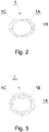
- the semi-transparent mirror 5, 5' other means may be used for altering the direction of the radiation beam, being means for partially transmitting the radiation, in particular in the visual range, wherein the means for partially transmitting the radiation are also means for partially reflecting the electromagnetic radiation beam. Due to the perspective in the radiation receiver 6, for example in the camera, an image is obtained which shows a contour of an end 1A of the tube 1 which is smaller than a contour 1B as presented in Fig. 2 in an enlarged view.
- An area 1C being an inner surface of the tube between the ends 1A and 1B is visible on the image obtained in the camera as significantly darker than an area limited by the contour of the end 1A.
- a second radiation beam 3' from a radiation source 4' passes through the semi-transparent mirror 5' and through the interior of the tube 1 in a second direction opposite to the first direction, wherein the radiation beam 3' after exiting the tube 1 is reflected from the second semi-transparent mirror 5 and propagates to the receiver 6.
- an image is obtained which shows the contour 1B of the tube 1 smaller than the contour 1A due to the perspective as presented in fig. 3 in an enlarged view.
- the first and the second radiation beam 3, 3' propagate in opposite directions.
- the semi-transparent mirrors 5, 5' are mirrors which partially transmit the light incident on them, and partially reflect the light incident on them.
- the receiver 6 is connected to an inspection unit 9 for inspecting the quality of the tube, which on the basis of the received image determines if the quality of the tube 1 is appropriate.
- the inspection unit 9 determines a deviation of the shape with respect to the circular shape, for example it recognizes ovality, multangularity or the detected shape. In case of ovality or a regular or irregular multangularity of one of the ends 1A, 1B of the tube 1, the inspection unit 9 generates a signal to a controller 10 for rejecting the faulty tube 1.
- the faulty tube 1 may be rejected from the transporter 2 in a known manner or may be rejected further after transmittal to another transporter.
- the faulty tubes 1 will be also recognized as tubes having deviation from the circular shape of one of their ends 1A, 1B only on a certain section of their circumference. Deformation of both ends 1A, 1B of the tube 1 may indicate on the deformation of the tube 1 on its total length. Deformation towards the inside may signify the indentation of the tube on its total length, while the deformation towards the outside may signify that the tube is glued improperly.
- radiation exiting from the radiation source 4 is divided into two radiation beams 3, 3'.
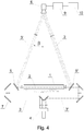
- the first radiation beam 3 is reflected from three consecutive mirrors 7, passes through the first semi-transparent mirror 5, and further through the interior of the tube 1 in the first direction and after being reflected from the second semi-transparent mirror 5' it propagates towards the receiver 6.
- the second radiation beam 3 is reflected from the three consecutive mirrors 7, propagates through the second semi-transparent mirror 5', and further through the interior of the tube 1 in the second direction opposite to the first direction, and after being reflected from the first semi-transparent mirror 5 it propagates towards the receiver 6.
- means for altering the direction of the radiation beam include means for reflecting the radiation and means for partially reflecting the radiation.
- the means for reflecting the radiation and means for partially reflecting the radiation may have a form of totally reflecting mirrors or semi-reflecting mirrors or may have a form of totally reflecting optical prisms or semi-reflecting optical prisms.
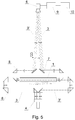
- a third embodiment presented in fig. 5 having a structure analogous to the embodiment from fig. 4 , the mirrors 7 and optical prisms 8 are located on the path of the radiation 3, 3' directed to the interior of the tube 1.
- the angle ⁇ is decreased, and therefore higher convergence of the radiation beams 3, 3' toward the receiver 6 is obtained, which provides lower deformations of the registered image.
- the first radiation beam 3 is directed from the radiation source 4 to the first semi-reflecting optical prism 8, and reflected from an inner reflecting surface of said optical prism is directed by means of the mirrors assembly 7 towards the inside of tube 1, and directed through the interior of the tube 1 in the first direction, and directed by the mirrors assembly 7 towards a second semi-reflecting optical prism 8' and further through the second optical prism 8' to the radiation receiver 6.
- the second radiation beam 3' is directed from the radiation source 4' to the second semi-reflecting optical prism 8', and reflected from said optical prism is directed by means of the mirrors assembly 7 towards the inside of tube 1, and directed through the interior of the tube 1 in the second direction opposite to the first direction, and directed by the mirrors assembly 7 towards the first optical prism 8 and further through said optical prism is directed to the radiation receiver 6.
- the radiation beams 3, 3' are directed divergently on the path from the semi-reflecting optical prisms 8, 8' towards the mirrors assembly 7, which directs the radiation beams 3, 3' to the inside of the tube 1.
- An angle between the first radiation beam 3 and the second radiation beam 3' is equal to 2 ⁇ .
- the radiation beams 3, 3' are directed convergently on the path from the mirrors assembly 7 through the semi-reflecting optical prisms 8, 8' to the radiation receiver 6, wherein the angle between the first beam 3 and the second beam 3' is also equal to 2 ⁇ .
- a fifth embodiment presented in fig. 7 is analogous to the fourth embodiment, however the radiation source 4 (not shown in the drawing) is located in front of or behind the presented system (in front of or behind the plane of the drawing), and the radiation from the radiation source 4 is reflected from the semi-transparent mirror 5 (the plane of the mirror is inclined at an angle with respect to the plane of the drawing) and propagates towards the mirrors assembly 7. Further the path of the radiation beams 3, 3' is directed through the interior of the tube 1, to the mirror 7 and through the semi-transparent mirror 5 to the radiation receiver 6. The radiation beams 3, 3' are directed convergently towards the radiation receiver 6. Instead of the mirror, the optical prism may be used with the reflecting surface which is inclined with respect to the plane of the drawing. The radiation beams 3, 3' from the radiation source 4 after being reflected from the semi-reflecting mirror 5 are directed divergently. Instead of the single mirror 5, two mirrors 5, 5' providing reflecting of two beams 3, 3' divergently, may be used.
- a sixth embodiment presented in Fig. 8 is analogous to the fifth embodiment, wherein the radiation beams 3, 3' are directed in parallel with respect to each other both on the path from the radiation source to the mirrors 7, which direct the radiation beams to the inside of the tube 1 as well as in the directed towards the radiation receiver 6', which may have a form of a telecentric camera.
- a seventh embodiment is a modification of the fifth embodiment, wherein the radiation receiver 6 is located asymmetrically with respect to the transporter 2, and the path of the first radiation beam 3 and the path of the second radiation beam 3' are also asymmetric.
- the radiation receiver 6 is located axially with respect to the tube 1.
- the path of the first radiation source 3 extends from the radiation source 4 to the first semi-reflecting mirror 5, to the radiation reflecting mirrors 7, through the inside of the tube 1 in the first direction, and further through the second semi-reflecting mirror 5' to the radiation receiver 6, wherein the path of the second radiation source 3' from the second radiation source 4'extends to the second semi-reflecting mirror 5', and from the mirror 5' extends through the interior of the tube 1 in the second direction opposite to the first direction, and further to the mirrors 7 reflecting the radiation and through the first semi-reflecting mirror 5 to the radiation receiver 6.
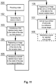
- Fig. 11 presents a method for inspecting quality of a tube, comprising the steps in which first in step 101 the tube 1 is provided to the inspecting system presented above, preferably by moving it transversally with respect to the axis of the tube.
- step 102 two radiation beams are generated, which are introduced to the inside of the tube.
- step 103 the first radiation beam is introduced to the inside of the tube in the first direction.
- step 104 an image generated by means of the first radiation beam, after propagating through the tube, is registered, wherein the image presents a contour of tube ends in a view towards the inside of the tube for the first radiation beam.
- the second radiation beam is introduced to the inside of the tube in the second direction opposite to the first direction.
- step 106 an image generated by means of the second radiation beam, after propagating through the tube, is registered, wherein the image presents a contour of tube ends in a view towards the inside of the tube for the second radiation beam.
- step 107 in a control unit, the contour of the tube end is compared with respect to the reference circular shape and in case of deviation of the registered shape of the tube end from the circular shape a signal for rejecting a faulty tube may be generated in step 108.
Landscapes
- General Health & Medical Sciences (AREA)
- Health & Medical Sciences (AREA)
- Chemical & Material Sciences (AREA)
- Physics & Mathematics (AREA)
- Analytical Chemistry (AREA)
- Biochemistry (AREA)
- Life Sciences & Earth Sciences (AREA)
- General Physics & Mathematics (AREA)
- Immunology (AREA)
- Pathology (AREA)
- Toxicology (AREA)
- Investigating Materials By The Use Of Optical Means Adapted For Particular Applications (AREA)
- Control Of Metal Rolling (AREA)
- Heat Treatment Of Articles (AREA)
- Extrusion Moulding Of Plastics Or The Like (AREA)
Abstract
Description
- The present disclosure relates to a tube quality inspection system and a method for inspecting a tube, in particular in tobacco industry machines.
- In tobacco industry, semi-finished products such as filtering material rods, multichannel rods, rods made of spongy material, thin-walled and thick-walled tubes and other rods, which are needed for forming a smoke stream or for producing scent, are used for manufacturing rod-like elements such as filters with a mouthpiece or multi-segment filter rods. During transportation of such elements, usually in a form of mass-flow by means of trays, the elements may become deformed. It is caused by the fact that sometimes the elements are transported in the mass-flow over long distances wherein the direction of displacement is altered, and the elements in the tray may be squeezed under pressure of remaining elements.
- Most of the filled rod-like elements exhibit some resilience, however paperboard or paper tube rod-like elements, in particular which are thin-walled, are substantially easily deformable. Due to the necessity of maintaining high quality of finished products, there is a need for inspecting the quality of semi-products, in particular their shape, wherein the deformation of the element may be accessed basing on the shape of its end.
- From the state of the art there are known systems for quality inspection, in which cameras for inspecting the shape of rod-like elements are used.
- A US patent document
US4976544 discloses a device equipped with a camera for inspecting the circularity of cigarette ends located in the tray. The device is equipped with a rejecting unit for rejecting faulty cigarettes. - An
PCT publication WO 2015/138440 discloses a device, in which by means of a camera an image of rod-like elements ends is registered, and in case of lack of circularity of the tip the element may be rejected from production. - A European patent application
EP2677273 discloses an optical device for inspecting the quality of rod-like elements which are transported in ducts of a drum, wherein the quality inspection is performed by means of optical devices, for example by means of a camera. The rod-like elements are transferred by means of a drum transporter transversally to the direction of in which the quality inspection of both ends is performed. - A US patent document
US5519494A discloses a measurement device for inspecting surface roughness of tubes, in which a source of radiation and a receiver are located at the opposite ends of the inspected tube. For registering images of both ends of the rod-like element, including the tube element, it is essential to use two cameras, which significantly increases costs of the measurement device. - An object of the invention is an inspection system for controlling quality of a tube, comprising: transporting means for transferring the tube on a transporting path being substantially perpendicular to an axis of the tube, a radiation source, a radiation receiver, and means for altering a direction of a radiation beam, partially or totally reflecting the radiation, forming the path of the radiation beam from the radiation source through the interior of the tube to the receiver. The system is characterized in that the inspection system is configured to generate two radiation beams and to introduce said two radiation beams to the inside of the tube at two opposite ends of the tube, such that the radiation beams propagate through the tube in two opposite directions.
- The means for altering the direction of the radiation beam comprise a semi-transparent mirror.
- The means for altering the direction of the radiation beam comprise a mirror.
- The means for altering the direction of the radiation beam comprise an optical prism.
- The radiation receiver is configured to receive both radiation beams.
- The radiation beams propagate in parallel with respect to each other on the path to the radiation receiver.
- The radiation beams propagate convergently on the path to the radiation receiver.
- The radiation beams propagate in parallel with respect to each other on the path from the radiation source.
- The radiation beams propagate divergently on the path from the radiation source.
- Preferably, in the inspection system the radiation source, the radiation receiver and the means for altering the direction of the radiation beam are arranged such that the path of the radiation beam extends from the radiation source to the means partially reflecting the radiation, from these means propagates through the radiation reflecting means through the interior of the tube, through radiation reflecting means and propagates through the means partially reflecting the radiation, to the radiation receiver.
- Preferably, in the inspection system the radiation source, the radiation receiver and means for altering the direction of the radiation beam are distributed such that the path of the first radiation beam from the first radiation source extends to the first means partially reflecting the radiation, from these means propagates through radiation reflecting means, through the interior of the tube, through the radiation reflecting means and propagates through the second means partially reflecting the radiation, to the radiation receiver, wherein the path of the second radiation beam from the second radiation source extends to the second means partially reflecting the radiation, from these means propagates through the radiation reflecting means and the interior of the tube, through the radiation reflecting means and propagates through the first means partially reflecting the radiation, to the radiation receiver.
- Preferably, in the inspection system the radiation source, the radiation receiver and the means for altering the direction of the radiation beam are distributed such that the path of the first radiation beam extends from the radiation source to the first means partially reflecting the radiation, through the radiation reflecting means through the interior of the tube, further through the second means party reflecting the radiation, to the radiation receiver, wherein the path of the second radiation beam from the second radiation source extends to the second means partially reflecting the radiation, from these means propagates through the interior of the tube, further through the radiation reflecting means and through the first means partially reflecting the radiation, to the radiation receiver.
- Preferably, in the inspection system the radiation source, the radiation receiver and the means for altering the direction of the radiation beam are distributed such that the path of the first radiation beam extends from the radiation source to the radiation reflecting means, from these means through the first means partially reflecting the radiation, through the interior of the tube, to the second means party reflecting the radiation and to the radiation receiver, wherein the path of the second radiation beam extends from the radiation source to the radiation reflecting means, and from these means through the second means party reflecting the radiation, through the interior of the tube, and to the first means party reflecting the radiation and to the radiation receiver.
- Preferably, in the inspection system the radiation sources, the radiation receiver and the means for altering the direction of the radiation beam are distributed such that the path of the first radiation beam from the first radiation source extends through the first means party reflecting the radiation, through the interior of the tube, to the second means party reflecting the radiation and to the radiation receiver, wherein the path of the second radiation beam from the second radiation source extends through the second means party reflecting the radiation, through the interior of the tube, to the first means party reflecting the radiation and to the radiation receiver.
- In the inspection system, the image receiver may be connected to an inspection unit for inspecting the quality of the tube.
- In the inspection system, the inspection unit may generate a signal to a controller for rejecting the faulty tube.
- An object of the invention is also a method for inspecting quality of a tube comprising the steps of: providing the tube to an inspection system; generating two radiation beams; introducing the first radiation beam do the inside of the tube in a first direction; registering an image generated by means of the first radiation beam after propagating through the tube; introducing the second radiation beam do the inside of the tube in a second direction opposite to the first direction; registering an image generated by means of the second radiation beam after propagating through the tube; comparing a contour of tube ends to a circular shape in an inspection unit.
- In case of deviation of the registered shape from the circular shape, a signal for rejecting a faulty tube is generated.
- The present invention is shown by means of example embodiments in a drawing, in which:
-
Fig. 1 presents an inspection system in a first embodiment; -
Fig. 2 presents an image of a tube in a view at a first end side; -
Fig. 3 presents an image of the tube in a view at a second end side; -
Fig. 4 presents the inspection system in a second embodiment; -
Fig. 5 presents the inspection system in a third embodiment; -
Fig. 6 presents the inspection system in a fourth embodiment; -
Fig. 7 presents the inspection system in a fifth embodiment; -
Fig. 8 presents the inspection system in a sixth embodiment; -
Fig. 9 presents the inspection system in a seventh embodiment; -
Fig. 10 presents the inspection system in an eighth embodiment; and -
Fig. 11 presents a method for inspecting the quality of the tube; - A
tube 1 to be inspected, presented infig. 1 is located on atransporter 2, for example it may be located in aduct 2A of a belt transporter or of a drum transporter. Locating the tube in the duct provides its stable positioning during inspection (measurement). In an inspection system according to the invention, sources and receivers of electromagnetic radiation in the visual range are used, however it is possible to use electromagnetic radiation in a different range, for example an infrared electromagnetic radiation. In the inspection system, radiation beams may be directed in parallel to each other or divergently, i.e. such that the beam extends in some degree in the direction of incidence. Afirst radiation beam 3, from aradiation source 4, passes through asemi-transparent mirror 5, and through an interior of thetube 1 in a first direction, wherein theradiation beam 3 after exiting from thetube 1 is reflected from a semi-transparent mirror 5' and propagates to areceiver 6. Instead of thesemi-transparent mirror 5, 5', other means may be used for altering the direction of the radiation beam, being means for partially transmitting the radiation, in particular in the visual range, wherein the means for partially transmitting the radiation are also means for partially reflecting the electromagnetic radiation beam. Due to the perspective in theradiation receiver 6, for example in the camera, an image is obtained which shows a contour of anend 1A of thetube 1 which is smaller than acontour 1B as presented inFig. 2 in an enlarged view. Anarea 1C being an inner surface of the tube between theends end 1A. A second radiation beam 3' from a radiation source 4' passes through the semi-transparent mirror 5' and through the interior of thetube 1 in a second direction opposite to the first direction, wherein the radiation beam 3' after exiting thetube 1 is reflected from the secondsemi-transparent mirror 5 and propagates to thereceiver 6. In the camera an image is obtained which shows thecontour 1B of thetube 1 smaller than thecontour 1A due to the perspective as presented infig. 3 in an enlarged view. Inside thetube 1, the first and thesecond radiation beam 3, 3' propagate in opposite directions. The inspection system presented infig. 1 has a plane of symmetry k being simultaneously a plane of symmetry of thetransporter 2, presented as a rotary drum having axis of rotation m, thesemi-transparent mirrors 5, 5' located at an angle α with respect to the plane k such, that the radiation beams 3, 3' reflected from themirrors 5, 5' propagate convergently towards thereceiver 6, wherein eachradiation beam 3, 3' propagates at an angle β with respect to the plane k. - The
semi-transparent mirrors 5, 5' are mirrors which partially transmit the light incident on them, and partially reflect the light incident on them. - The
receiver 6 is connected to aninspection unit 9 for inspecting the quality of the tube, which on the basis of the received image determines if the quality of thetube 1 is appropriate. Theinspection unit 9 determines a deviation of the shape with respect to the circular shape, for example it recognizes ovality, multangularity or the detected shape. In case of ovality or a regular or irregular multangularity of one of theends tube 1, theinspection unit 9 generates a signal to acontroller 10 for rejecting thefaulty tube 1. Thefaulty tube 1 may be rejected from thetransporter 2 in a known manner or may be rejected further after transmittal to another transporter. Thefaulty tubes 1 will be also recognized as tubes having deviation from the circular shape of one of theirends tube 1 may indicate on the deformation of thetube 1 on its total length. Deformation towards the inside may signify the indentation of the tube on its total length, while the deformation towards the outside may signify that the tube is glued improperly. - In a second embodiment presented in
fig. 4 , radiation exiting from theradiation source 4 is divided into tworadiation beams 3, 3'. Thefirst radiation beam 3 is reflected from threeconsecutive mirrors 7, passes through the firstsemi-transparent mirror 5, and further through the interior of thetube 1 in the first direction and after being reflected from the second semi-transparent mirror 5' it propagates towards thereceiver 6. Thesecond radiation beam 3 is reflected from the threeconsecutive mirrors 7, propagates through the second semi-transparent mirror 5', and further through the interior of thetube 1 in the second direction opposite to the first direction, and after being reflected from the firstsemi-transparent mirror 5 it propagates towards thereceiver 6. Instead of themirrors 7 and thesemi-transparent mirrors 5, 5' other means may be used for altering the direction of the radiation beam, being means for totally or partially reflecting the electromagnetic radiation, in particular in the visible range. According to the present description, means for altering the direction of the radiation beam include means for reflecting the radiation and means for partially reflecting the radiation. Both, the means for reflecting the radiation and means for partially reflecting the radiation may have a form of totally reflecting mirrors or semi-reflecting mirrors or may have a form of totally reflecting optical prisms or semi-reflecting optical prisms. - In a third embodiment presented in
fig. 5 , having a structure analogous to the embodiment fromfig. 4 , themirrors 7 andoptical prisms 8 are located on the path of theradiation 3, 3' directed to the interior of thetube 1. In this embodiment the angle β is decreased, and therefore higher convergence of the radiation beams 3, 3' toward thereceiver 6 is obtained, which provides lower deformations of the registered image. - In a fourth embodiment presented in
fig. 6 , thefirst radiation beam 3 is directed from theradiation source 4 to the first semi-reflectingoptical prism 8, and reflected from an inner reflecting surface of said optical prism is directed by means of themirrors assembly 7 towards the inside oftube 1, and directed through the interior of thetube 1 in the first direction, and directed by themirrors assembly 7 towards a second semi-reflecting optical prism 8' and further through the second optical prism 8' to theradiation receiver 6. Wherein the second radiation beam 3' is directed from the radiation source 4' to the second semi-reflecting optical prism 8', and reflected from said optical prism is directed by means of themirrors assembly 7 towards the inside oftube 1, and directed through the interior of thetube 1 in the second direction opposite to the first direction, and directed by themirrors assembly 7 towards the firstoptical prism 8 and further through said optical prism is directed to theradiation receiver 6. The radiation beams 3, 3' are directed divergently on the path from the semi-reflectingoptical prisms 8, 8' towards themirrors assembly 7, which directs the radiation beams 3, 3' to the inside of thetube 1. An angle between thefirst radiation beam 3 and the second radiation beam 3' is equal to 2β. The radiation beams 3, 3' are directed convergently on the path from themirrors assembly 7 through the semi-reflectingoptical prisms 8, 8' to theradiation receiver 6, wherein the angle between thefirst beam 3 and the second beam 3' is also equal to 2β. - A fifth embodiment presented in
fig. 7 is analogous to the fourth embodiment, however the radiation source 4 (not shown in the drawing) is located in front of or behind the presented system (in front of or behind the plane of the drawing), and the radiation from theradiation source 4 is reflected from the semi-transparent mirror 5 (the plane of the mirror is inclined at an angle with respect to the plane of the drawing) and propagates towards themirrors assembly 7. Further the path of the radiation beams 3, 3' is directed through the interior of thetube 1, to themirror 7 and through thesemi-transparent mirror 5 to theradiation receiver 6. The radiation beams 3, 3' are directed convergently towards theradiation receiver 6. Instead of the mirror, the optical prism may be used with the reflecting surface which is inclined with respect to the plane of the drawing. The radiation beams 3, 3' from theradiation source 4 after being reflected from thesemi-reflecting mirror 5 are directed divergently. Instead of thesingle mirror 5, twomirrors 5, 5' providing reflecting of twobeams 3, 3' divergently, may be used. - A sixth embodiment presented in
Fig. 8 is analogous to the fifth embodiment, wherein the radiation beams 3, 3' are directed in parallel with respect to each other both on the path from the radiation source to themirrors 7, which direct the radiation beams to the inside of thetube 1 as well as in the directed towards the radiation receiver 6', which may have a form of a telecentric camera. - A seventh embodiment is a modification of the fifth embodiment, wherein the
radiation receiver 6 is located asymmetrically with respect to thetransporter 2, and the path of thefirst radiation beam 3 and the path of the second radiation beam 3' are also asymmetric. - In an eight embodiment presented in
fig. 10 , theradiation receiver 6 is located axially with respect to thetube 1. The path of thefirst radiation source 3 extends from theradiation source 4 to the firstsemi-reflecting mirror 5, to theradiation reflecting mirrors 7, through the inside of thetube 1 in the first direction, and further through the second semi-reflecting mirror 5' to theradiation receiver 6, wherein the path of the second radiation source 3' from the second radiation source 4'extends to the second semi-reflecting mirror 5', and from the mirror 5' extends through the interior of thetube 1 in the second direction opposite to the first direction, and further to themirrors 7 reflecting the radiation and through the firstsemi-reflecting mirror 5 to theradiation receiver 6. -
Fig. 11 presents a method for inspecting quality of a tube, comprising the steps in which first instep 101 thetube 1 is provided to the inspecting system presented above, preferably by moving it transversally with respect to the axis of the tube. Next, instep 102, two radiation beams are generated, which are introduced to the inside of the tube. Next, instep 103, the first radiation beam is introduced to the inside of the tube in the first direction. Instep 104, an image generated by means of the first radiation beam, after propagating through the tube, is registered, wherein the image presents a contour of tube ends in a view towards the inside of the tube for the first radiation beam. Next instep 105, the second radiation beam is introduced to the inside of the tube in the second direction opposite to the first direction. Next, instep 106 an image generated by means of the second radiation beam, after propagating through the tube, is registered, wherein the image presents a contour of tube ends in a view towards the inside of the tube for the second radiation beam. Instep 107, in a control unit, the contour of the tube end is compared with respect to the reference circular shape and in case of deviation of the registered shape of the tube end from the circular shape a signal for rejecting a faulty tube may be generated instep 108.
Claims (15)
- An inspection system for controlling quality of a tube (1), comprising:- transporting means (2) for transferring the tube (1) on a transporting path being substantially perpendicular to an axis of the tube (1),- a radiation source (4, 4'),- a radiation receiver (6), and- means for altering a direction of a radiation beam, partially or totally reflecting the radiation, forming the path of the radiation beam from the radiation source (4, 4') through the interior of the tube (1) to the radiation receiver (6),characterized in that:- the inspection system is configured to generate two radiation beams (3, 3') and to introduce said two radiation beams (3, 3') to the inside of the tube (1) at two opposite ends of the tube (1), such that the radiation beams (3, 3') propagate through the tube (1) in two opposite directions.
- The inspection system according to claim 1, characterized in that the means for altering the direction of the radiation beam comprise a semi-transparent mirror (5, 5').
- The inspection system according to claim 1, characterized in that the means for altering the direction of the radiation beam comprise a mirror (7).
- The inspection system according to claim 1, characterized in that the means for altering the direction of the radiation beam comprise an optical prism (8).
- The inspection system according to any of claims 1-4, characterized in that the radiation receiver (6) is configured to receive both radiation beams (3, 3').
- The inspection system according to any of claims 1-5, characterized in that the radiation beams (3, 3') propagate in parallel with respect to each other on the path to the radiation receiver (6').
- The inspection system according to any of claims 1-5, characterized in that the radiation beams (3, 3') propagate convergently on the path to the radiation receiver (6).
- The inspection system according to any of claims 1-7, characterized in that the radiation beams (3, 3') propagate in parallel with respect to each other on the path from the radiation source (4, 4').
- The inspection system according to any of claims 1-7, characterized in that the radiation beams (3, 3') propagate divergently on the path from the radiation source (4, 4').
- The inspection system according to any of claims 1-9, characterized in that the radiation source (4, 4'), the radiation receiver (6, 6') and the means (5, 5', 7) for altering the direction of the radiation beam are arranged such that the path of the radiation beam (3, 3') extends from the radiation source (4) to the means (5, 5') partially reflecting the radiation, from these means propagates through the radiation reflecting means (7) through the interior of the tube (1), through radiation reflecting means (7) and propagates through the means (5, 5') partially reflecting the radiation, to the radiation receiver (6, 6').
- The inspection system according to any of claims 1-9, characterized in that the radiation source (4, 4'), the radiation receiver (6) and means (7, 8, 8') for altering the direction of the radiation beam are distributed such that the path of the first radiation beam (3) from the first radiation source (4) extends to the first means (8) partially reflecting the radiation, from these means propagates through radiation reflecting means (7), through the interior of the tube (1), through the radiation reflecting means (7) and propagates through the second means (8') partially reflecting the radiation, to the radiation receiver (6), wherein the path of the second radiation beam (3') from the second radiation source (4') extends to the second means (8') partially reflecting the radiation, from these means propagates through the radiation reflecting means (7) and the interior of the tube (1), through the radiation reflecting means (7) and propagates through the first means (8) partially reflecting the radiation, to the radiation receiver (6).
- The inspection system according to any of claims 1-9, characterized in that the radiation source (4, 4'), the radiation receiver (6) and the means (5, 5', 7) for altering the direction of the radiation beam are distributed such that the path of the first radiation beam (3) extends from the radiation source (4) to the first means (5) partially reflecting the radiation, through the radiation reflecting means (7) through the interior of the tube (1), further through the second means (5') party reflecting the radiation, to the radiation receiver (6), wherein the path of the second radiation beam (3') from the second radiation source (4') extends to the second means (5') partially reflecting the radiation, from these means propagates through the interior of the tube (1), further through the radiation reflecting means (7) and through the first means (5) partially reflecting the radiation, to the radiation receiver (6).
- The inspection system according to any of claims 1-9, characterized in that the radiation source (4), the radiation receiver (6) and the means (5, 5', 7) for altering the direction of the radiation beam are distributed such that the path of the first radiation beam (3) extends from the radiation source (4) to the radiation reflecting means (7), from these means through the first means (5) partially reflecting the radiation, through the interior of the tube (1), to the second means (5') party reflecting the radiation and to the radiation receiver (6), wherein the path of the second radiation beam (3') extends from the radiation source (4) to the radiation reflecting means (7), and from these means through the second means (5') party reflecting the radiation, through the interior of the tube (1), and to the first means (5) party reflecting the radiation and to the radiation receiver (6).
- The inspection system according to any of claims 1-9, characterized in that the radiation sources (4, 4'), the radiation receiver (6) and the means (5, 5', 7) for altering the direction of the radiation beam are distributed such that the path of the first radiation beam (3) from the first radiation source (4) extends through the first means (5) party reflecting the radiation, through the interior of the tube (1), to the second means (5') party reflecting the radiation and to the radiation receiver (6), wherein the path of the second radiation beam (3') from the second radiation source (4') extends through the second means (5') party reflecting the radiation, through the interior of the tube (1), to the first means (5) party reflecting the radiation and to the radiation receiver (6).
- A method for inspecting a quality of a tube comprising the steps of:- providing (101) the tube to an inspection system;- generating (102) two radiation beams;- introducing (103) the first radiation beam do the inside of the tube in a first direction;- registering (104) an image generated by means of the first radiation beam after propagating through the tube;- introducing (105) the second radiation beam do the inside of the tube in a second direction opposite to the first direction;- registering (106) an image generated by means of the second radiation beam after propagating through the tube;- comparing (107) a contour of tube ends to a circular shape in an inspection unit;- in case of deviation of the registered shape from the circular shape a signal for rejecting a faulty tube is generated (108).
Priority Applications (6)
| Application Number | Priority Date | Filing Date | Title |
|---|---|---|---|
| PT191662154T PT3714707T (en) | 2019-03-29 | 2019-03-29 | A measuring system for controlling a quality of a tube and a method for controlling a quality of a tube |
| ES19166215T ES2935707T3 (en) | 2019-03-29 | 2019-03-29 | A measurement system for controlling the quality of a tube and a method for controlling the quality of a tube |
| PL19166215.4T PL3714707T3 (en) | 2019-03-29 | 2019-03-29 | A measuring system for controlling a quality of a tube and a method for controlling a quality of a tube |
| EP19166215.4A EP3714707B1 (en) | 2019-03-29 | 2019-03-29 | A measuring system for controlling a quality of a tube and a method for controlling a quality of a tube |
| LTEP19166215.4T LT3714707T (en) | 2019-03-29 | 2019-03-29 | A measuring system for controlling a quality of a tube and a method for controlling a quality of a tube |
| RU2020111336A RU2776149C2 (en) | 2019-03-29 | 2020-03-19 | Checking system for quality control of tube and method for quality control of tube |
Applications Claiming Priority (1)
| Application Number | Priority Date | Filing Date | Title |
|---|---|---|---|
| EP19166215.4A EP3714707B1 (en) | 2019-03-29 | 2019-03-29 | A measuring system for controlling a quality of a tube and a method for controlling a quality of a tube |
Publications (2)
| Publication Number | Publication Date |
|---|---|
| EP3714707A1 true EP3714707A1 (en) | 2020-09-30 |
| EP3714707B1 EP3714707B1 (en) | 2022-11-02 |
Family
ID=66529738
Family Applications (1)
| Application Number | Title | Priority Date | Filing Date |
|---|---|---|---|
| EP19166215.4A Active EP3714707B1 (en) | 2019-03-29 | 2019-03-29 | A measuring system for controlling a quality of a tube and a method for controlling a quality of a tube |
Country Status (5)
| Country | Link |
|---|---|
| EP (1) | EP3714707B1 (en) |
| ES (1) | ES2935707T3 (en) |
| LT (1) | LT3714707T (en) |
| PL (1) | PL3714707T3 (en) |
| PT (1) | PT3714707T (en) |
Citations (13)
| Publication number | Priority date | Publication date | Assignee | Title |
|---|---|---|---|---|
| JPS50149394A (en) * | 1974-05-21 | 1975-11-29 | ||
| US3980567A (en) | 1974-03-22 | 1976-09-14 | Amf Incorporated | Optical cigarette end inspection method and device |
| US4025201A (en) | 1975-04-21 | 1977-05-24 | Ball Brothers Service Corporation | Method and apparatus for video inspection of articles of manufacture by decussate paths of light |
| JPS62150609U (en) * | 1986-03-18 | 1987-09-24 | ||
| US4976544A (en) | 1988-06-29 | 1990-12-11 | G.D. Societa' Per Azioni | Method of inspecting the ends of stacked cigarettes |
| US5519494A (en) | 1993-06-08 | 1996-05-21 | Kabushiki Kaisha Kobe Seiko Sho | Pipe inner surface measuring method and apparatus |
| CN201059965Y (en) | 2007-03-29 | 2008-05-14 | 中国电子科技集团公司第四十一研究所 | Cylindrical material deformation detection device |
| US20130070240A1 (en) * | 2011-09-15 | 2013-03-21 | William J. Crann, JR. | Apparatus and method for inspecting the inner surface of a tubular structure for contamination |
| EP2677273A1 (en) | 2012-06-14 | 2013-12-25 | HAUNI Maschinenbau AG | Measuring device and method for optically examining a front surface of a transversally conveyed rod-shaped product of the tobacco processing industry |
| EP2918180A1 (en) | 2014-02-21 | 2015-09-16 | HAUNI Maschinenbau AG | Optical inspection of rod-shaped articles from the tobacco processing industry |
| WO2015138440A1 (en) | 2014-03-11 | 2015-09-17 | R. J. Reynolds Tobacco Company | Smoking article inspection system and associated method |
| EP3323738A1 (en) | 2016-11-17 | 2018-05-23 | Focke & Co. (GmbH & Co. KG) | Device and method for optical inspection of objects to be inspected when packaging products |
| DE202017006788U1 (en) * | 2017-04-07 | 2018-05-28 | Vitronic Dr.-Ing. Stein Bildverarbeitungssysteme Gmbh | Device for optically inspecting a cylinder inner wall |
-
2019
- 2019-03-29 ES ES19166215T patent/ES2935707T3/en active Active
- 2019-03-29 EP EP19166215.4A patent/EP3714707B1/en active Active
- 2019-03-29 PT PT191662154T patent/PT3714707T/en unknown
- 2019-03-29 LT LTEP19166215.4T patent/LT3714707T/en unknown
- 2019-03-29 PL PL19166215.4T patent/PL3714707T3/en unknown
Patent Citations (13)
| Publication number | Priority date | Publication date | Assignee | Title |
|---|---|---|---|---|
| US3980567A (en) | 1974-03-22 | 1976-09-14 | Amf Incorporated | Optical cigarette end inspection method and device |
| JPS50149394A (en) * | 1974-05-21 | 1975-11-29 | ||
| US4025201A (en) | 1975-04-21 | 1977-05-24 | Ball Brothers Service Corporation | Method and apparatus for video inspection of articles of manufacture by decussate paths of light |
| JPS62150609U (en) * | 1986-03-18 | 1987-09-24 | ||
| US4976544A (en) | 1988-06-29 | 1990-12-11 | G.D. Societa' Per Azioni | Method of inspecting the ends of stacked cigarettes |
| US5519494A (en) | 1993-06-08 | 1996-05-21 | Kabushiki Kaisha Kobe Seiko Sho | Pipe inner surface measuring method and apparatus |
| CN201059965Y (en) | 2007-03-29 | 2008-05-14 | 中国电子科技集团公司第四十一研究所 | Cylindrical material deformation detection device |
| US20130070240A1 (en) * | 2011-09-15 | 2013-03-21 | William J. Crann, JR. | Apparatus and method for inspecting the inner surface of a tubular structure for contamination |
| EP2677273A1 (en) | 2012-06-14 | 2013-12-25 | HAUNI Maschinenbau AG | Measuring device and method for optically examining a front surface of a transversally conveyed rod-shaped product of the tobacco processing industry |
| EP2918180A1 (en) | 2014-02-21 | 2015-09-16 | HAUNI Maschinenbau AG | Optical inspection of rod-shaped articles from the tobacco processing industry |
| WO2015138440A1 (en) | 2014-03-11 | 2015-09-17 | R. J. Reynolds Tobacco Company | Smoking article inspection system and associated method |
| EP3323738A1 (en) | 2016-11-17 | 2018-05-23 | Focke & Co. (GmbH & Co. KG) | Device and method for optical inspection of objects to be inspected when packaging products |
| DE202017006788U1 (en) * | 2017-04-07 | 2018-05-28 | Vitronic Dr.-Ing. Stein Bildverarbeitungssysteme Gmbh | Device for optically inspecting a cylinder inner wall |
Also Published As
| Publication number | Publication date |
|---|---|
| RU2020111336A (en) | 2021-09-20 |
| RU2020111336A3 (en) | 2021-12-27 |
| PL3714707T3 (en) | 2023-02-06 |
| ES2935707T3 (en) | 2023-03-09 |
| LT3714707T (en) | 2023-02-10 |
| EP3714707B1 (en) | 2022-11-02 |
| PT3714707T (en) | 2023-01-17 |
Similar Documents
| Publication | Publication Date | Title |
|---|---|---|
| CN1939165B (en) | Device and method for measuring properties of multi-segment filters or combinations of filter segments | |
| RU2649380C2 (en) | Method and device for detection of rotated segments in a multi-segment rod transferred in a machine used in tobacco industry | |
| CN108474746A (en) | Device for optical check object | |
| US4639592A (en) | Cigarette testing apparatus | |
| RU2636364C1 (en) | Method and system for manufacturing rod-shaped products | |
| EP2199883B1 (en) | A method of setting up and managing the inspection device in a machine for manufacturing tobacco products | |
| CN104856220A (en) | Optical Inspection Of Rod-shaped Articles From The Tobacco Processing Industry | |
| US6578583B2 (en) | Apparatus for making and inspecting multi-component wrapped article | |
| JP2004097226A (en) | Method for measuring length and/or diameter of virgulate filter and system therefor | |
| JP2019500629A (en) | Terahertz measurement method and terahertz measurement apparatus for calculating layer thickness or interval of measurement object | |
| US20170238599A1 (en) | Method and device for detection of rotated segments conveyed in a machine used in tobacco industry and a machine for producing multisegment rods comprising such a device | |
| TWI841484B (en) | Apparatus and method for inspecting a glass sheet | |
| US9933244B2 (en) | Reduced back reflection optical coherence tomography probe | |
| ITBO930297A1 (en) | OPTICAL CONTROL METHOD FOR CIGARETTE FILLING. | |
| US20050163363A1 (en) | Continuous filter rod testing | |
| JPH0628585B2 (en) | Method and apparatus for detecting the presence or absence of defects in rod-shaped articles in the tobacco processing industry | |
| EP3714707B1 (en) | A measuring system for controlling a quality of a tube and a method for controlling a quality of a tube | |
| EP3520631B1 (en) | Method and apparatus for inspecting the ends of rod-shaped segments of the tobacco industry | |
| RU2776149C2 (en) | Checking system for quality control of tube and method for quality control of tube | |
| GB2149101A (en) | Optically testing rod-shaped tobacco products | |
| US5301011A (en) | Method of and apparatus for ascertaining the diameters of rod-shaped articles | |
| PL239516B1 (en) | Measurement system for tube quality control and how to control tube quality | |
| EP4369954B1 (en) | A device and a method for manufacturing multi-segment rod-like articles | |
| EP4369956B1 (en) | A measuring system and a method for determining parameters of a multi-segment rod-like article | |
| EP4718021A1 (en) | Method for measuring at least one cross-sectional dimension of a cylindrical hollow body |
Legal Events
| Date | Code | Title | Description |
|---|---|---|---|
| PUAI | Public reference made under article 153(3) epc to a published international application that has entered the european phase |
Free format text: ORIGINAL CODE: 0009012 |
|
| STAA | Information on the status of an ep patent application or granted ep patent |
Free format text: STATUS: THE APPLICATION HAS BEEN PUBLISHED |
|
| AK | Designated contracting states |
Kind code of ref document: A1 Designated state(s): AL AT BE BG CH CY CZ DE DK EE ES FI FR GB GR HR HU IE IS IT LI LT LU LV MC MK MT NL NO PL PT RO RS SE SI SK SM TR |
|
| STAA | Information on the status of an ep patent application or granted ep patent |
Free format text: STATUS: REQUEST FOR EXAMINATION WAS MADE |
|
| TPAC | Observations filed by third parties |
Free format text: ORIGINAL CODE: EPIDOSNTIPA |
|
| 17P | Request for examination filed |
Effective date: 20210322 |
|
| RBV | Designated contracting states (corrected) |
Designated state(s): AL AT BE BG CH CY CZ DE DK EE ES FI FR GB GR HR HU IE IS IT LI LT LU LV MC MK MT NL NO PL PT RO RS SE SI SK SM TR |
|
| REG | Reference to a national code |
Ref country code: DE Ref legal event code: R079 Ref document number: 602019021298 Country of ref document: DE Free format text: PREVIOUS MAIN CLASS: A24F0047000000 Ipc: G01N0021954000 |
|
| RIC1 | Information provided on ipc code assigned before grant |
Ipc: G01N 21/952 20060101ALI20220406BHEP Ipc: A24C 5/34 20060101ALI20220406BHEP Ipc: G01N 21/954 20060101ALI20220406BHEP Ipc: A24F 47/00 20200101AFI20220406BHEP |
|
| GRAP | Despatch of communication of intention to grant a patent |
Free format text: ORIGINAL CODE: EPIDOSNIGR1 |
|
| STAA | Information on the status of an ep patent application or granted ep patent |
Free format text: STATUS: GRANT OF PATENT IS INTENDED |
|
| RIC1 | Information provided on ipc code assigned before grant |
Ipc: G01N 21/952 20060101ALI20220509BHEP Ipc: A24C 5/34 20060101ALI20220509BHEP Ipc: G01N 21/954 20060101AFI20220509BHEP |
|
| INTG | Intention to grant announced |
Effective date: 20220609 |
|
| GRAS | Grant fee paid |
Free format text: ORIGINAL CODE: EPIDOSNIGR3 |
|
| GRAA | (expected) grant |
Free format text: ORIGINAL CODE: 0009210 |
|
| STAA | Information on the status of an ep patent application or granted ep patent |
Free format text: STATUS: THE PATENT HAS BEEN GRANTED |
|
| AK | Designated contracting states |
Kind code of ref document: B1 Designated state(s): AL AT BE BG CH CY CZ DE DK EE ES FI FR GB GR HR HU IE IS IT LI LT LU LV MC MK MT NL NO PL PT RO RS SE SI SK SM TR |
|
| REG | Reference to a national code |
Ref country code: GB Ref legal event code: FG4D |
|
| REG | Reference to a national code |
Ref country code: CH Ref legal event code: EP Ref country code: AT Ref legal event code: REF Ref document number: 1529091 Country of ref document: AT Kind code of ref document: T Effective date: 20221115 |
|
| REG | Reference to a national code |
Ref country code: DE Ref legal event code: R096 Ref document number: 602019021298 Country of ref document: DE |
|
| REG | Reference to a national code |
Ref country code: IE Ref legal event code: FG4D |
|
| REG | Reference to a national code |
Ref country code: RO Ref legal event code: EPE |
|
| REG | Reference to a national code |
Ref country code: PT Ref legal event code: SC4A Ref document number: 3714707 Country of ref document: PT Date of ref document: 20230117 Kind code of ref document: T Free format text: AVAILABILITY OF NATIONAL TRANSLATION Effective date: 20230111 |
|
| REG | Reference to a national code |
Ref country code: NL Ref legal event code: FP |
|
| REG | Reference to a national code |
Ref country code: SE Ref legal event code: TRGR |
|
| REG | Reference to a national code |
Ref country code: ES Ref legal event code: FG2A Ref document number: 2935707 Country of ref document: ES Kind code of ref document: T3 Effective date: 20230309 |
|
| REG | Reference to a national code |
Ref country code: AT Ref legal event code: MK05 Ref document number: 1529091 Country of ref document: AT Kind code of ref document: T Effective date: 20221102 |
|
| PG25 | Lapsed in a contracting state [announced via postgrant information from national office to epo] |
Ref country code: NO Free format text: LAPSE BECAUSE OF FAILURE TO SUBMIT A TRANSLATION OF THE DESCRIPTION OR TO PAY THE FEE WITHIN THE PRESCRIBED TIME-LIMIT Effective date: 20230202 Ref country code: FI Free format text: LAPSE BECAUSE OF FAILURE TO SUBMIT A TRANSLATION OF THE DESCRIPTION OR TO PAY THE FEE WITHIN THE PRESCRIBED TIME-LIMIT Effective date: 20221102 Ref country code: AT Free format text: LAPSE BECAUSE OF FAILURE TO SUBMIT A TRANSLATION OF THE DESCRIPTION OR TO PAY THE FEE WITHIN THE PRESCRIBED TIME-LIMIT Effective date: 20221102 |
|
| PGFP | Annual fee paid to national office [announced via postgrant information from national office to epo] |
Ref country code: LT Payment date: 20230302 Year of fee payment: 5 |
|
| PG25 | Lapsed in a contracting state [announced via postgrant information from national office to epo] |
Ref country code: RS Free format text: LAPSE BECAUSE OF FAILURE TO SUBMIT A TRANSLATION OF THE DESCRIPTION OR TO PAY THE FEE WITHIN THE PRESCRIBED TIME-LIMIT Effective date: 20221102 Ref country code: LV Free format text: LAPSE BECAUSE OF FAILURE TO SUBMIT A TRANSLATION OF THE DESCRIPTION OR TO PAY THE FEE WITHIN THE PRESCRIBED TIME-LIMIT Effective date: 20221102 Ref country code: IS Free format text: LAPSE BECAUSE OF FAILURE TO SUBMIT A TRANSLATION OF THE DESCRIPTION OR TO PAY THE FEE WITHIN THE PRESCRIBED TIME-LIMIT Effective date: 20230302 Ref country code: HR Free format text: LAPSE BECAUSE OF FAILURE TO SUBMIT A TRANSLATION OF THE DESCRIPTION OR TO PAY THE FEE WITHIN THE PRESCRIBED TIME-LIMIT Effective date: 20221102 Ref country code: GR Free format text: LAPSE BECAUSE OF FAILURE TO SUBMIT A TRANSLATION OF THE DESCRIPTION OR TO PAY THE FEE WITHIN THE PRESCRIBED TIME-LIMIT Effective date: 20230203 |
|
| PGFP | Annual fee paid to national office [announced via postgrant information from national office to epo] |
Ref country code: SE Payment date: 20230315 Year of fee payment: 5 Ref country code: PT Payment date: 20230310 Year of fee payment: 5 |
|
| PGFP | Annual fee paid to national office [announced via postgrant information from national office to epo] |
Ref country code: NL Payment date: 20230326 Year of fee payment: 5 |
|
| P01 | Opt-out of the competence of the unified patent court (upc) registered |
Effective date: 20230528 |
|
| PG25 | Lapsed in a contracting state [announced via postgrant information from national office to epo] |
Ref country code: SM Free format text: LAPSE BECAUSE OF FAILURE TO SUBMIT A TRANSLATION OF THE DESCRIPTION OR TO PAY THE FEE WITHIN THE PRESCRIBED TIME-LIMIT Effective date: 20221102 Ref country code: EE Free format text: LAPSE BECAUSE OF FAILURE TO SUBMIT A TRANSLATION OF THE DESCRIPTION OR TO PAY THE FEE WITHIN THE PRESCRIBED TIME-LIMIT Effective date: 20221102 Ref country code: DK Free format text: LAPSE BECAUSE OF FAILURE TO SUBMIT A TRANSLATION OF THE DESCRIPTION OR TO PAY THE FEE WITHIN THE PRESCRIBED TIME-LIMIT Effective date: 20221102 Ref country code: CZ Free format text: LAPSE BECAUSE OF FAILURE TO SUBMIT A TRANSLATION OF THE DESCRIPTION OR TO PAY THE FEE WITHIN THE PRESCRIBED TIME-LIMIT Effective date: 20221102 |
|
| PGFP | Annual fee paid to national office [announced via postgrant information from national office to epo] |
Ref country code: ES Payment date: 20230403 Year of fee payment: 5 |
|
| REG | Reference to a national code |
Ref country code: DE Ref legal event code: R097 Ref document number: 602019021298 Country of ref document: DE |
|
| PG25 | Lapsed in a contracting state [announced via postgrant information from national office to epo] |
Ref country code: SK Free format text: LAPSE BECAUSE OF FAILURE TO SUBMIT A TRANSLATION OF THE DESCRIPTION OR TO PAY THE FEE WITHIN THE PRESCRIBED TIME-LIMIT Effective date: 20221102 Ref country code: AL Free format text: LAPSE BECAUSE OF FAILURE TO SUBMIT A TRANSLATION OF THE DESCRIPTION OR TO PAY THE FEE WITHIN THE PRESCRIBED TIME-LIMIT Effective date: 20221102 |
|
| PLBE | No opposition filed within time limit |
Free format text: ORIGINAL CODE: 0009261 |
|
| STAA | Information on the status of an ep patent application or granted ep patent |
Free format text: STATUS: NO OPPOSITION FILED WITHIN TIME LIMIT |
|
| 26N | No opposition filed |
Effective date: 20230803 |
|
| PG25 | Lapsed in a contracting state [announced via postgrant information from national office to epo] |
Ref country code: MC Free format text: LAPSE BECAUSE OF FAILURE TO SUBMIT A TRANSLATION OF THE DESCRIPTION OR TO PAY THE FEE WITHIN THE PRESCRIBED TIME-LIMIT Effective date: 20221102 |
|
| GBPC | Gb: european patent ceased through non-payment of renewal fee |
Effective date: 20230329 |
|
| PG25 | Lapsed in a contracting state [announced via postgrant information from national office to epo] |
Ref country code: SI Free format text: LAPSE BECAUSE OF FAILURE TO SUBMIT A TRANSLATION OF THE DESCRIPTION OR TO PAY THE FEE WITHIN THE PRESCRIBED TIME-LIMIT Effective date: 20221102 |
|
| REG | Reference to a national code |
Ref country code: BE Ref legal event code: MM Effective date: 20230331 |
|
| PG25 | Lapsed in a contracting state [announced via postgrant information from national office to epo] |
Ref country code: LU Free format text: LAPSE BECAUSE OF NON-PAYMENT OF DUE FEES Effective date: 20230329 |
|
| REG | Reference to a national code |
Ref country code: IE Ref legal event code: MM4A |
|
| PG25 | Lapsed in a contracting state [announced via postgrant information from national office to epo] |
Ref country code: GB Free format text: LAPSE BECAUSE OF NON-PAYMENT OF DUE FEES Effective date: 20230329 |
|
| PG25 | Lapsed in a contracting state [announced via postgrant information from national office to epo] |
Ref country code: IE Free format text: LAPSE BECAUSE OF NON-PAYMENT OF DUE FEES Effective date: 20230329 Ref country code: GB Free format text: LAPSE BECAUSE OF NON-PAYMENT OF DUE FEES Effective date: 20230329 Ref country code: FR Free format text: LAPSE BECAUSE OF NON-PAYMENT OF DUE FEES Effective date: 20230331 |
|
| PG25 | Lapsed in a contracting state [announced via postgrant information from national office to epo] |
Ref country code: BE Free format text: LAPSE BECAUSE OF NON-PAYMENT OF DUE FEES Effective date: 20230331 |
|
| REG | Reference to a national code |
Ref country code: LT Ref legal event code: MM4D Effective date: 20240329 |
|
| REG | Reference to a national code |
Ref country code: SE Ref legal event code: EUG |
|
| REG | Reference to a national code |
Ref country code: NL Ref legal event code: MM Effective date: 20240401 |
|
| PG25 | Lapsed in a contracting state [announced via postgrant information from national office to epo] |
Ref country code: BG Free format text: LAPSE BECAUSE OF FAILURE TO SUBMIT A TRANSLATION OF THE DESCRIPTION OR TO PAY THE FEE WITHIN THE PRESCRIBED TIME-LIMIT Effective date: 20221102 |
|
| PG25 | Lapsed in a contracting state [announced via postgrant information from national office to epo] |
Ref country code: BG Free format text: LAPSE BECAUSE OF FAILURE TO SUBMIT A TRANSLATION OF THE DESCRIPTION OR TO PAY THE FEE WITHIN THE PRESCRIBED TIME-LIMIT Effective date: 20221102 |
|
| PG25 | Lapsed in a contracting state [announced via postgrant information from national office to epo] |
Ref country code: NL Free format text: LAPSE BECAUSE OF NON-PAYMENT OF DUE FEES Effective date: 20240401 |
|
| PG25 | Lapsed in a contracting state [announced via postgrant information from national office to epo] |
Ref country code: NL Free format text: LAPSE BECAUSE OF NON-PAYMENT OF DUE FEES Effective date: 20240401 |
|
| PG25 | Lapsed in a contracting state [announced via postgrant information from national office to epo] |
Ref country code: LT Free format text: LAPSE BECAUSE OF NON-PAYMENT OF DUE FEES Effective date: 20240329 |
|
| PG25 | Lapsed in a contracting state [announced via postgrant information from national office to epo] |
Ref country code: LT Free format text: LAPSE BECAUSE OF NON-PAYMENT OF DUE FEES Effective date: 20240329 |
|
| PGFP | Annual fee paid to national office [announced via postgrant information from national office to epo] |
Ref country code: IT Payment date: 20250319 Year of fee payment: 7 |
|
| REG | Reference to a national code |
Ref country code: ES Ref legal event code: FD2A Effective date: 20250429 |
|
| PG25 | Lapsed in a contracting state [announced via postgrant information from national office to epo] |
Ref country code: ES Free format text: LAPSE BECAUSE OF NON-PAYMENT OF DUE FEES Effective date: 20240330 |
|
| PGFP | Annual fee paid to national office [announced via postgrant information from national office to epo] |
Ref country code: CH Payment date: 20250401 Year of fee payment: 7 |
|
| PG25 | Lapsed in a contracting state [announced via postgrant information from national office to epo] |
Ref country code: CY Free format text: LAPSE BECAUSE OF FAILURE TO SUBMIT A TRANSLATION OF THE DESCRIPTION OR TO PAY THE FEE WITHIN THE PRESCRIBED TIME-LIMIT; INVALID AB INITIO Effective date: 20190329 |
|
| PG25 | Lapsed in a contracting state [announced via postgrant information from national office to epo] |
Ref country code: PT Free format text: LAPSE BECAUSE OF NON-PAYMENT OF DUE FEES Effective date: 20240329 |
|
| PG25 | Lapsed in a contracting state [announced via postgrant information from national office to epo] |
Ref country code: HU Free format text: LAPSE BECAUSE OF FAILURE TO SUBMIT A TRANSLATION OF THE DESCRIPTION OR TO PAY THE FEE WITHIN THE PRESCRIBED TIME-LIMIT; INVALID AB INITIO Effective date: 20190329 |
|
| PG25 | Lapsed in a contracting state [announced via postgrant information from national office to epo] |
Ref country code: SE Free format text: LAPSE BECAUSE OF NON-PAYMENT OF DUE FEES Effective date: 20240330 |
|
| REG | Reference to a national code |
Ref country code: CH Ref legal event code: R17 Free format text: ST27 STATUS EVENT CODE: U-0-0-R10-R17 (AS PROVIDED BY THE NATIONAL OFFICE) Effective date: 20251127 |
|
| PG25 | Lapsed in a contracting state [announced via postgrant information from national office to epo] |
Ref country code: TR Free format text: LAPSE BECAUSE OF FAILURE TO SUBMIT A TRANSLATION OF THE DESCRIPTION OR TO PAY THE FEE WITHIN THE PRESCRIBED TIME-LIMIT Effective date: 20221102 |
|
| REG | Reference to a national code |
Ref country code: CH Ref legal event code: U11 Free format text: ST27 STATUS EVENT CODE: U-0-0-U10-U11 (AS PROVIDED BY THE NATIONAL OFFICE) Effective date: 20260401 |
|
| PGFP | Annual fee paid to national office [announced via postgrant information from national office to epo] |
Ref country code: DE Payment date: 20260320 Year of fee payment: 8 |
|
| PGFP | Annual fee paid to national office [announced via postgrant information from national office to epo] |
Ref country code: RO Payment date: 20260320 Year of fee payment: 8 |
|
| PGFP | Annual fee paid to national office [announced via postgrant information from national office to epo] |
Ref country code: PL Payment date: 20260323 Year of fee payment: 8 |