EP3714371B1 - Intelligent write protection cache (iwpc) in an adaptive private network (apn) - Google Patents
Intelligent write protection cache (iwpc) in an adaptive private network (apn) Download PDFInfo
- Publication number
- EP3714371B1 EP3714371B1 EP18881156.6A EP18881156A EP3714371B1 EP 3714371 B1 EP3714371 B1 EP 3714371B1 EP 18881156 A EP18881156 A EP 18881156A EP 3714371 B1 EP3714371 B1 EP 3714371B1
- Authority
- EP
- European Patent Office
- Prior art keywords
- data
- digest
- apn
- wan
- egress
- Prior art date
- Legal status (The legal status is an assumption and is not a legal conclusion. Google has not performed a legal analysis and makes no representation as to the accuracy of the status listed.)
- Active
Links
Images



Classifications
-
- H—ELECTRICITY
- H04—ELECTRIC COMMUNICATION TECHNIQUE
- H04L—TRANSMISSION OF DIGITAL INFORMATION, e.g. TELEGRAPHIC COMMUNICATION
- H04L12/00—Data switching networks
- H04L12/28—Data switching networks characterised by path configuration, e.g. LAN [Local Area Networks] or WAN [Wide Area Networks]
- H04L12/2854—Wide area networks, e.g. public data networks
-
- G—PHYSICS
- G06—COMPUTING OR CALCULATING; COUNTING
- G06F—ELECTRIC DIGITAL DATA PROCESSING
- G06F12/00—Accessing, addressing or allocating within memory systems or architectures
- G06F12/02—Addressing or allocation; Relocation
- G06F12/08—Addressing or allocation; Relocation in hierarchically structured memory systems, e.g. virtual memory systems
- G06F12/0802—Addressing of a memory level in which the access to the desired data or data block requires associative addressing means, e.g. caches
-
- G—PHYSICS
- G06—COMPUTING OR CALCULATING; COUNTING
- G06F—ELECTRIC DIGITAL DATA PROCESSING
- G06F21/00—Security arrangements for protecting computers, components thereof, programs or data against unauthorised activity
- G06F21/60—Protecting data
- G06F21/62—Protecting access to data via a platform, e.g. using keys or access control rules
- G06F21/6218—Protecting access to data via a platform, e.g. using keys or access control rules to a system of files or objects, e.g. local or distributed file system or database
-
- H—ELECTRICITY
- H04—ELECTRIC COMMUNICATION TECHNIQUE
- H04L—TRANSMISSION OF DIGITAL INFORMATION, e.g. TELEGRAPHIC COMMUNICATION
- H04L67/00—Network arrangements or protocols for supporting network services or applications
- H04L67/50—Network services
- H04L67/56—Provisioning of proxy services
- H04L67/568—Storing data temporarily at an intermediate stage, e.g. caching
-
- H—ELECTRICITY
- H04—ELECTRIC COMMUNICATION TECHNIQUE
- H04L—TRANSMISSION OF DIGITAL INFORMATION, e.g. TELEGRAPHIC COMMUNICATION
- H04L9/00—Cryptographic mechanisms or cryptographic arrangements for secret or secure communications; Network security protocols
- H04L9/06—Cryptographic mechanisms or cryptographic arrangements for secret or secure communications; Network security protocols the encryption apparatus using shift registers or memories for block-wise or stream coding, e.g. DES systems or RC4; Hash functions; Pseudorandom sequence generators
- H04L9/0643—Hash functions, e.g. MD5, SHA, HMAC or f9 MAC
-
- H—ELECTRICITY
- H04—ELECTRIC COMMUNICATION TECHNIQUE
- H04L—TRANSMISSION OF DIGITAL INFORMATION, e.g. TELEGRAPHIC COMMUNICATION
- H04L9/00—Cryptographic mechanisms or cryptographic arrangements for secret or secure communications; Network security protocols
- H04L9/32—Cryptographic mechanisms or cryptographic arrangements for secret or secure communications; Network security protocols including means for verifying the identity or authority of a user of the system or for message authentication, e.g. authorization, entity authentication, data integrity or data verification, non-repudiation, key authentication or verification of credentials
- H04L9/3236—Cryptographic mechanisms or cryptographic arrangements for secret or secure communications; Network security protocols including means for verifying the identity or authority of a user of the system or for message authentication, e.g. authorization, entity authentication, data integrity or data verification, non-repudiation, key authentication or verification of credentials using cryptographic hash functions
- H04L9/3239—Cryptographic mechanisms or cryptographic arrangements for secret or secure communications; Network security protocols including means for verifying the identity or authority of a user of the system or for message authentication, e.g. authorization, entity authentication, data integrity or data verification, non-repudiation, key authentication or verification of credentials using cryptographic hash functions involving non-keyed hash functions, e.g. modification detection codes [MDCs], MD5, SHA or RIPEMD
-
- G—PHYSICS
- G06—COMPUTING OR CALCULATING; COUNTING
- G06F—ELECTRIC DIGITAL DATA PROCESSING
- G06F15/00—Digital computers in general; Data processing equipment in general
- G06F15/16—Combinations of two or more digital computers each having at least an arithmetic unit, a program unit and a register, e.g. for a simultaneous processing of several programs
-
- G—PHYSICS
- G06—COMPUTING OR CALCULATING; COUNTING
- G06F—ELECTRIC DIGITAL DATA PROCESSING
- G06F2212/00—Indexing scheme relating to accessing, addressing or allocation within memory systems or architectures
- G06F2212/10—Providing a specific technical effect
- G06F2212/1052—Security improvement
-
- H—ELECTRICITY
- H04—ELECTRIC COMMUNICATION TECHNIQUE
- H04L—TRANSMISSION OF DIGITAL INFORMATION, e.g. TELEGRAPHIC COMMUNICATION
- H04L12/00—Data switching networks
- H04L12/28—Data switching networks characterised by path configuration, e.g. LAN [Local Area Networks] or WAN [Wide Area Networks]
-
- H—ELECTRICITY
- H04—ELECTRIC COMMUNICATION TECHNIQUE
- H04L—TRANSMISSION OF DIGITAL INFORMATION, e.g. TELEGRAPHIC COMMUNICATION
- H04L12/00—Data switching networks
- H04L12/54—Store-and-forward switching systems
- H04L12/56—Packet switching systems
-
- H—ELECTRICITY
- H04—ELECTRIC COMMUNICATION TECHNIQUE
- H04L—TRANSMISSION OF DIGITAL INFORMATION, e.g. TELEGRAPHIC COMMUNICATION
- H04L2101/00—Indexing scheme associated with group H04L61/00
- H04L2101/30—Types of network names
- H04L2101/375—Access point names [APN]
-
- H—ELECTRICITY
- H04—ELECTRIC COMMUNICATION TECHNIQUE
- H04L—TRANSMISSION OF DIGITAL INFORMATION, e.g. TELEGRAPHIC COMMUNICATION
- H04L43/00—Arrangements for monitoring or testing data switching networks
-
- H—ELECTRICITY
- H04—ELECTRIC COMMUNICATION TECHNIQUE
- H04L—TRANSMISSION OF DIGITAL INFORMATION, e.g. TELEGRAPHIC COMMUNICATION
- H04L45/00—Routing or path finding of packets in data switching networks
-
- H—ELECTRICITY
- H04—ELECTRIC COMMUNICATION TECHNIQUE
- H04L—TRANSMISSION OF DIGITAL INFORMATION, e.g. TELEGRAPHIC COMMUNICATION
- H04L45/00—Routing or path finding of packets in data switching networks
- H04L45/74—Address processing for routing
- H04L45/742—Route cache; Operation thereof
Definitions
- APN Adaptive Private Network
- WAN optimization is a networking improvement designed to increase bandwidth efficiency across the network for bulk traffic files and other information viewed by more than one user frequently.
- Common examples of this type of data are software updates and shared documents that would be beneficial to transmit once, and use for multiple users.
- WANop devices can cache data traversing the network and recognize when that data is being duplicated so that a reference to the cached data can be sent across the WAN in place of the duplicate data.
- WANop also improves the network by adding compression to network protocols that do not already compress data. The benefit of using WANop is that existing network applications can utilize less WAN bandwidth with no changes to the applications themselves.
- the present invention recognizes that providing improved wide area network (WAN) optimization at lower costs in a network is advantageous.
- WAN wide area network
- data and a digest of the data is sent.
- the digest is stored in a WPC.
- the digest and data are stored on a main disk and the digest is removed from the WPC.
- the digest is sent as the data is already stored on the main disk.
- an embodiment of the invention applies a method for reducing data storage.
- An APN appliance is a device that contains APN client site functionality including software modules which governs its participation in an APN.
- a high availability (HA) site contains two APNAs, one that is active and one that is in a standby mode of operation and available to become active in place of the other APNA if required.
- a WAN link represents a physical access point to the wide area network (WAN), such as a digital subscriber line (DSL) connection or a cable modem.
- WAN wide area network
- DSL digital subscriber line
- the distinctive characteristic of a WAN link is the bandwidth, representing the amount of data capacity available for transmission and reception.
- WAN links can be shared among APN conduits, and intranet and Internet network services.
- the APN appliances do not directly attach to WAN links.
- APN appliances communicate with WAN links through logical connections, such as the WAN routers 110 1 -110 3 of Fig. 1A .
- a private WAN link provides a physical access point to non-public WAN destinations.
- Examples of such private WAN links include an asynchronous transfer mode (ATM) link with an ATM virtual circuit, a frame relay link with a frame relay circuit, a multiprotocol label switching (MPLS) tunnel, a virtual private network (VPN) tunnel, or a leased point-to-point line.
- ATM asynchronous transfer mode
- MPLS multiprotocol label switching
- VPN virtual private network
- Connectivity on a network having a private WAN link is made to a private list of destinations on the other end of the network.
- a public WAN link represents a physical access point to the Internet. It can be assumed that any public WAN link can establish a connection to any other public WAN link.
- a local WAN link is an APN client site's access point to a WAN.
- a site A's LWL is coupled to a corresponding remote WAN link (RWL) for a site B.
- RWL remote WAN link
- site A's local WAN links are site B's remote WAN links.
- An Internet service is used for traffic between an enterprise site and sites on the public Internet.
- the Internet is treated as a separate security zone. Traffic on the Internet is considered less trustworthy than conduit traffic in an APN because the Internet traffic has not been encapsulated and encrypted as is done in a conduit. Also, the Internet traffic is generally coming from an entity not under control of the enterprise that owns the trusted network.
- An intranet service is used for any portion of enterprise intranet traffic that has not been defined for transmission across a conduit.
- the intranet traffic remains unencapsulated, and the APN manages bandwidth in the network by rate-limiting the intranet traffic relative to other service types during times of congestion.
- traffic that ordinarily travels via a conduit may instead be treated as intranet traffic in order to maintain network reliability.
- conduit traffic is site-to-site, customers generally have a way to deliver this site-to-site traffic without the conduit.
- This unencapsulated service called an intranet service, does not receive the benefits of the conduit. If the conduit tunnel cannot be brought up, then routes which use that conduit are ignored and this means that traffic that would have used the conduit are redirected to use an unencapsulated site-to-site transport method.
- An APN service is a set of processing steps performed on packets that are transmitted through the APN. As illustrated in Fig. 1A , data traffic that moves through the APN 100 and APN appliance 106 may require different types of services depending on where the sending and receiving stations are located.
- An APN service instance is a particular configured contextual instance of an APN service held in an APN appliance memory 107 internal to the APN appliance 106, for example.
- An APN service instance's memory contains, but is not limited to, context specific configuration data, statistical data, and tracking states data.
- an APN client site may have multiple APN conduits that connect to remote APN client sites. For each APN conduit there exists a separate APN service instance for the APN conduit service type.
- An APN conduit service associated with path 112 manages network traffic packets that are transmitted through the APN 100 from the APN appliance 105 through router 110 1 , through the WAN 102, through another router 110 3 to APN appliance (APNA) 104.
- the APN conduit service for path 112 operates on both APN appliances 104 and 105.
- the APN conduit service sends and receives data between a first geographic location that has the APNA 105 and a different geographic location that has the APNA 104 utilizing the full benefits provided by the APN conduit service for WAN resource allocation and network adaptation.
- An APN intranet service associated with path 114 is used to manage the sending and receiving of data between a first geographic location that has the APN appliance 105 and a different geographic location within an enterprise non-APN site 120 that does not have an APN appliance by way of a WAN link that is also utilized by other APN services.
- an APN intranet service such as the one associated with path 112 may be used to send and receive data to and from a different geographic location that has an APN appliance, but an administrator selectively configures the APN not to use the APN conduit service 112 for a particular type or class of traffic.
- An APN Internet service associated with path 116 is used to send and receive data between a first geographic location that has the APNA 105 and a different geographic location that is external to an enterprise network by way of a WAN link that is also utilized by other APN services.
- traffic using the APN Internet service may be associated with a network user accessing a public Internet web server 122.
- a conduit consists of multiple paths.
- a path is formed between 2 WAN links associated with the conduit.
- Each path in each conduit in the APN is monitored for quality of communication by collecting quality metrics such as packet loss and latency. This monitoring is done by way of control messages and is done on each path whether the path is used to transmit user traffic or not. Accordingly, no path is completely free of traffic unless it is not operational. Since all paths within a conduit are being measured whether there is user traffic through the path or not, the conduit maintains up to date per-path metrics that are used by the APN to select the best network path to transmit user data.
- APN path processing services are responsible for providing a means of communicating user data and control information from one APN node to another APN node across the network.
- user data and control information may be transmitted from the WAN ingress processor module 160 of one APN node across the WAN and received at the WAN egress processor module 166, as shown for example in Fig. 1B .
- a path state represents the most current condition of the network path as determined by feedback received by the WAN egress APN node's path state monitoring process. As packets are received, the sequence numbers of the packets are tracked to see if any packets were lost in transit between the WAN ingress APN node and the WAN egress APN node.
- a method is used to trigger path state transitions that are biased toward more tolerance for loss in the short periods of packets received with substantially less tolerance of loss over longer periods.
- a unique aspect of this approach is the ability to track the path's packet loss thresholds over numerous durations nearly simultaneously and continually while still maintaining low processor overhead.
- This aspect is obtained through the universal path tagging of conduit traffic sent across the WAN with high resolution and highly synchronized APN time stamps to enable the highly predictive estimation of transmission latency and statistical variation of latency.
- a control plane modules' path state monitoring service is used to detect packet loss and optimal paths for traffic to use across the APN. The result is an ability to detect a difference between occasional incidental short term network loss and long term persistent problems.
- the APN node's software modules at a client site are stored and operate in the same physical APN appliance; however, the modules may also exist in separate physical APN appliances in alternative embodiments.
- the methods described in connection with the embodiments disclosed herein may be embodied directly in one or more software modules executed by a processor and memory complex such as utilized in an adaptive private network (APN) appliance (APNA), a rack mounted processing device, a personal computer, a server, or the like, having one or more central processing unit devices.
- API adaptive private network
- the processor and memory complex may be configured to execute instructions that access data and operate on data under control of a software module program stored on a computer readable non-transitory storage medium either directly associated locally with the processor and memory complex, such as may be available through an instruction cache, or accessible through an I/O device.
- a software module may reside in a computer readable non-transitory storage medium which may include random access memory (RAM), flash memory, dynamic random access memory (DRAM), synchronous dynamic random access memory (SDRAM), read only memory (ROM), programmable read only memory (PROM), erasable programmable read only memory (EPROM), electrically erasable programmable read only memory (EEPROM), hard disk, a removable disk, a CD-ROM, digital video disk (DVD), other types of removable disks, or any other suitable non-transitory storage medium.
- RAM random access memory
- DRAM dynamic random access memory
- SDRAM synchronous dynamic random access memory
- ROM read only memory
- PROM programmable read only memory
- EPROM erasable programmable read only memory
- EEPROM electrically erasable programmable read only memory
- hard disk a removable disk
- CD-ROM compact disc-read only memory
- DVD digital video disk
- DVD digital video disk
- An adaptive private network node contains software modules supporting participation in an adaptive private network.
- An APN node may exist in one or more APN appliances at a location.
- An APN node contains a collection of software modules executed by a processor and memory complex located in the APN node which govern the APN node's participation within an APN such as control plane modules 156 and 158, WAN ingress processor modules 160 and 162, and WAN egress processor modules 164 and 166 in Fig. 1B .
- the control plane modules 156 and 158 are responsible for controlling and participating in the control of the APN node in tandem with other APN nodes in the network.
- the WAN ingress processor module 160 may suitably be embodied as software and hardware components responsible for processing network traffic for transmission from a local area network (LAN) to a WAN.
- the WAN egress processor module 164 may suitably be embodied as software operating on hardware components, such as a processor and memory complex that is responsible for processing network traffic for transmission from a WAN to a LAN.
- WAN ingress and WAN egress processor modules are discussed in further detail below.
- the APN client site's control plane module 156 may suitably be embodied as software operating on hardware components, such as a processor and memory complex that utilizes the APN client site's WAN ingress processor module 160 and WAN egress processor module 164 as the means for transmitting and receiving APN node to APN node control data across the WAN.
- TAP Tapplication protocol
- the TAP is a protocol for messages that are sent through the WAN to allow processes outside of t2_app on different appliances to communicate with each other.
- TAP can be considered a point-to-point or Ethernet like device which, instead of receiving packets from physical media, receives the packets from a user program and instead of sending packets via the physical media, writes the packets to the user program.
- the central configuration also provides for additional configuration bandwidth optimization for the network, by doing a mapping of the APN resources and their initial allocations. Furthermore, the centralized configuration can provide information and warnings to the administrator as to the behavior of the configuration that may not be obvious or intended from the configuration, before loading the configuration onto a production network.
- Each of the sites 204-219 and primary NCN site 202 contains an APN appliance to provide APN functionality.
- the configuration of the APN 200 generally provides for connectivity between a site A, such as site 205, and for a site B, such as site 208, where the connectivity from the site A's perspective is site A ⁇ LWL ⁇ "WAN" ⁇ RWL ⁇ site B.
- the connectivity from the site B's perspective is site B ⁇ LWL ⁇ "WAN" ⁇ RWL ⁇ site A.
- the WAN 201 represents allocated WAN link resources and APN selected paths.
- a conduit between a site A and a site B is formed by use of the conduit sections 222 and 225 and is a virtual connection between the corresponding site A and site B.
- the conduit includes a collection of paths and encompasses a path from a local WAN link (LWL) at site A ⁇ "WAN" ⁇ RWL at site B.
- LWL local WAN link
- APN conduits exist between the NCN and, for example, sixteen APN client sites as shown in Fig. 2 . It will be recognized that while sixteen APN sites are shown for purposes of illustration, a larger or smaller number of potential APN client sites may be suitably employed.
- Each APN conduit may have the unique configuration parameters tailored by an administrator for the particular needs of each geographic location associated with a particular APN.
- an APN appliance is a device that contains APN node functionality according to software modules, such as the control plane modules 156 and 158, the WAN ingress processor modules 160 and 162, and the WAN egress processor modules 164 and 166, as described in more detail above with reference to Fig. 1B .
- the sixteen client sites 204-219 are coupled by conduit sections 221-236, respectively, and the conduit sections may be connected together to provide a configurable virtual connection between two connected APN appliances at the client sites. It is noted that while sixteen client sites 204-219 are illustrated, an APN may support as many client sites as are required.
- a network control point (NCP) 202 of Fig. 2 is an administration point for the APN 200.
- the NCP 202 resides within an APN node.
- An APN control node refers to an APN node that also performs as the network control point of the APN.
- an NCP resides in an appliance that is separate from an APN node and administers and controls the APN nodes within the APN.
- the NCP provides administrative and control to the APN, including but not limited to, distribution of configuration objects to APN client nodes and time synchronization to the APN.
- a dynamic conduit is a conduit created between APN clients when needed and can be removed when no longer needed, based on a configured threshold.
- client site 205 can be configured with two local WAN links, one from a first network provider and one from a second network provider. Multiple conduits may be connected to site 205 which may be configured to use one or both of the local WAN links. In an exemplary scenario where all of the conduits that are connected to site 205 use both local WAN links, then when usage for either local WAN link passes the configured threshold, creation of a dynamic conduit can be triggered.
- DWPD drive writes per day
- WPC write protection cache
- WANop a collection of techniques for increasing data transfer efficiencies across the WAN.
- Peer 2 350 may suitably be a WAN ingress processor which processes network traffic for transmission from a local area network (LAN) connected to a client device, such as a laptop, from which the client sends a client stream 360 for transmission of data to cloud storage through WAN cloud packet input-output (I/O) connection 368.
- LAN local area network
- client device such as a laptop
- client stream 360 for transmission of data to cloud storage through WAN cloud packet input-output (I/O) connection 368.
- I/O WAN cloud packet input-output
- the data passes through a 64k input buffer to a deduplication process 362, a compression process 364 and a 64k output buffer 366.
- the data structure for storing the digest is 64 bytes, and the average chunk of data is 8kB.
- WANop's memory of previously seen data becomes approximately 128 times larger than the WPC.
- a one megabyte WPC contains 16k digests representing 128 megabytes of chunk data.
- a 3.5GB WPC provides a 10 hour memory of unique chunks representing 439GB of data. Similar data for other platforms is provided in Table 500 of Fig. 5 .
- Fig. 6 shows a process 600 for processing a request for a previously unseen chunk received by the WAN ingress peer.
- the chunk is not in the WPC or on the disk.
- the digest is sent to the WAN egress peer in step 604.
- the WAN egress peer replies with a NACK in step 606.
- the WAN ingress peer sends over the chunk's data in step 608.
- the WAN egress peer adds the digest to the WPC and forwards the data to the LAN in step 610.
- Fig. 7 shows a process 700 for processing a chunk seen for the second time.
- step 702 when the same chunk is received by the WAN ingress peer, the digest is again sent to the WAN egress peer. The digest is determined not to be on the disk in step 704 and the WAN egress peer replies with a NACK in step 706.
- step 708 the ingress peer sends the chunk's data to the WAN egress peer.
- the digest for the chunk is found in the WPC as a result of it being added in step 610.
- the data is added to the disk and the digest is removed from the WPC in step 710.
- step 712 the data is forwarded to the LAN.
- Fig. 8 shows a process 800 for processing a chunk seen for the third and subsequent times.
- a chunk is seen for a third or subsequent time
- that chunk comprising data and digest is sent to egress peer in step 804.
- the digest sent in step 804 corresponds to a chunk already stored on the disk and an ACK is sent to the ingress peer.
- the egress peer forwards the data to the LAN.
- Figs. 9A and 9B illustrate process flows 900 and 950, respectively.
- a WAN egress peer receives a chunk digest from an ingress peer.
- the egress peer performs a lookup operation to determine if the received digest is stored on the disk which in a presently preferred embodiment is a semiconductor storage device (SSD).
- step 906 if the determination in step 904 is "No", then process 900 continues by sending a NACK response to the ingress peer. If the determination is "Yes" in step 906, then the chunk data is sent to the LAN in step 908 and the ACK response is sent to the ingress peer in step 910.
- step 952 of process 950 of Fig. 9B the egress peer receives a NACK reply from ingress peer with chunk data including the digest.
- the egress peer proceeds in step 954 to lookup the digest in the disk cache to see if it is there. If it is determined the digest is on the disk cache in step 956, the egress peer proceeds to determine if the chunk data is stored in the WPC in step 958. If yes, in step 960, the chunk is added to the disk storage.
- step 962 the digest is deleted from the WPC and in step 966, the chunk data is sent to the LAN.
- step 968 an ACK response is sent to the ingress peer. If in step 958, the determination is "no" the digest is not in the WPC, the digest is added to the WPC in step 964.
- step 966 the chunk data is sent to the LAN.
- step 968 the ACK response is sent to the ingress peer.
- each entry in the presently preferred WPC is 64 bytes(B) and contains a chunk digest.
- all entries are on a free list.
- entries move from the free list to the in use list.
- the WPC gets a hit, the entry is removed from the in use list, and placed back on the free list.
- the oldest entry on the in use list is freed and used for the new entry.
- the oldest entry of a certain size could be freed up. For example, the oldest entry or entries less than a certain size would be deleted before a similarly old entry of a larger size.
- virtual appliances operate in the same manner as a regular appliance, but the virtual appliance must adjust its scalability and resource requirements based on the underlying virtual memory (VM) configuration.
- VM virtual memory
- WANop memory requirement sizes are based on total memory.
Landscapes
- Engineering & Computer Science (AREA)
- Computer Security & Cryptography (AREA)
- Signal Processing (AREA)
- Computer Networks & Wireless Communication (AREA)
- Theoretical Computer Science (AREA)
- Physics & Mathematics (AREA)
- General Engineering & Computer Science (AREA)
- General Physics & Mathematics (AREA)
- Computer Hardware Design (AREA)
- Software Systems (AREA)
- General Health & Medical Sciences (AREA)
- Bioethics (AREA)
- Health & Medical Sciences (AREA)
- Databases & Information Systems (AREA)
- Power Engineering (AREA)
- Data Exchanges In Wide-Area Networks (AREA)
Description
- The present application claims the priority of
U.S. Patent Application Serial No. 16/196,358 filed November 20, 2018 U.S. Provisional Patent Application Serial No. 62/589,163 filed November 21, 2017 - The present application is also related to
U.S. Patent Application Serial No. 14/146,786 filed on January 3, 2014 U.S. Patent Application Serial No. 13/592,460 filed on August 23, 2012 U.S. Patent No. 8,644,164 which is a continuation ofU.S. Patent Application Serial No. 13/353,693 filed on January 19, 2012 U.S. Patent No. 8,274,891 which claims the benefit of and priority toU.S. Patent Application No. 12/482,766 filed on June 11, 2009 U.S. Patent No. 8,125,907 entitled "Flow-Based Adaptive Private Network with Multiple WAN-Paths", all of which claim the benefit ofU.S. Provisional Patent Application No. 61/060,846 entitled "Flow-based Adaptive Private Network with Multiple WAN-Paths" filed June 12, 2008 U.S. Patent Application Serial No. 14/291,776 filed on May 30, 2014 U.S. Patent Application Serial No. 13/850,411 filed on March 26, 2013 U.S. Patent No. 8,775,547 and which is a continuation ofU.S. Patent Application Serial No. 13/208,825 filed on August 12, 2011 U.S. Patent No. 8,452,846 , all of which claim the benefit ofU.S. Provisional Patent Application Serial No. 61/372,904 entitled "Adaptive Private Network Asynchronous Distributed Shared Memory Services" filed August 12, 2010 U.S. Patent Application Serial No. 13/719,433 filed on December 19, 2012 U.S. Patent Application Serial No. 14/019,723 filed on September 6, 2013 entitled "An Adaptive Private Network with Path Maximum Transmission Unit (MTU) Discovery Process";U.S. Patent Application Serial No. 14/481,335 filed on September 9, 2014 U.S. Patent Application Serial No. 14/972,270, filed December 17, 2015 U.S. Patent Application Serial No. 14/972,353, filed December 17, 2015 U.S. Patent Application Serial No. 14/972,514, filed December 17, 2015 U.S. Patent Application Serial No. 14/973,193, filed December 17, 2015 U.S. Patent Application Serial No. 14/973,343, filed December 17, 2015 U.S. Patent Application Serial No. 15/409,001 filed on January 18, 2017 U.S. Patent Application Serial No. 2017-0207996 A1 entitled "Methods and Apparatus for Configuring a Standby WAN Link in an Adaptive Private Network";U.S. Patent Application Serial No. 15/409,006 filed on January 18, 2017 U.S. Patent Application Serial No. 2017-0207997 A1 entitled "Methods And Apparatus For Accessing Selectable Application Processing Of Data Packets In An Adaptive Private Network";U.S. Patent Application Serial No. 15/409,016 filed on January 18, 2017 U.S. Patent Application Serial No. 2017-0207963 A1 entitled "Methods and Apparatus for Accessing Dynamic Routing Information from Networks Coupled to a Wide Area Network (WAN) to Determine Optimized End-To-End Routing Paths"; andU.S. Patent Application Serial No. 15/409,019 filed on January 18, 2017 U.S. Patent Application Serial No. 2017-0207976 A1 entitled "Adaptive Private Network (APN) Bandwidth Enhancements", all of which have the same assignee as the present application, are related applications. - The present invention relates generally to improved wide area network (WAN) optimization and smart caching techniques. More specifically, the present invention relates to using disk and RAM resources to manage the cache of network data used for deduplication, the reduction or elimination of duplication, in the context of an adaptive private network (APN).
- WAN optimization (WANop) is a networking improvement designed to increase bandwidth efficiency across the network for bulk traffic files and other information viewed by more than one user frequently. Common examples of this type of data are software updates and shared documents that would be beneficial to transmit once, and use for multiple users. WANop devices can cache data traversing the network and recognize when that data is being duplicated so that a reference to the cached data can be sent across the WAN in place of the duplicate data. WANop also improves the network by adding compression to network protocols that do not already compress data. The benefit of using WANop is that existing network applications can utilize less WAN bandwidth with no changes to the applications themselves.
- Products doing wide area network (WAN) optimization (WANop) have to deal with a difficult problem when doing deduplication regarding having a finite limit of RAM and disk storage available on the appliance. When network data is seen, a network node appliance has no way to know whether that data will be seen again. In one prior approach, WANop wrote directly to the disk any new data that it received on either ingress or egress. Among its several aspects the present invention recognizes that this approach may result in significant drive wear and may replace warm chunks of data that are frequently in use with non-repeating data. This invention also recognizes that caching all data requires large amounts of RAM and disk storage to deal with high bandwidth WAN links and that significantly raises the price of WANop network devices. The present invention further recognizes that ideally, network devices want to only cache data that will be seen again in the future. This invention also recognizes that the most common transfer of data is from information that is stored in a data center that is accessed repeatedly by multiple users at a given client site.
- Also, solid state drive (SSD) technology, although amazingly fast, has a significantly shorter life span than a hard disk drive (HDD). For example, a 128MB drive may fail after writing only 14TB of data. There may be financial ramifications to a company providing a warranty if the drive fails within an appliance warranty period.
US 2014/201384 A1 discloses a method for optimizing WAN traffic with an efficient index scheme. Further techniques belonging to the prior art are disclosed in Daehee Kim ET AL: "Existing Deduplication Techniques", Chapter 2: "Data Deduplication for Data Optimization for Storage and Network Systems", which classifies existing deduplication techniques based on granularity, place of deduplication, and deduplication time. Reference is made to the specific deduplication disclosed in section 2.4.3, titled "End-to-End Redundancy Elimination". - Among its several aspects, the present invention recognizes that providing improved wide area network (WAN) optimization at lower costs in a network is advantageous. Rather than always saving data in the context as described herein, data and a digest of the data is sent. Upon seeing the data a first time, the digest is stored in a WPC. Upon seeing the data a second time and the same digest being transferred, the digest and data are stored on a main disk and the digest is removed from the WPC. Thereafter, with the third and any following transfer, only the digest is sent as the data is already stored on the main disk. To such ends, an embodiment of the invention applies a method for reducing data storage. The method comprises receiving data and a digest of the data for a first time; storing the digest in a write protect cache in response to making a determination that this is the first time the data and digest have been received; receiving the data and the digest of the data for a second time; storing the data and the digest of the data on a main disk and removing the digest from the write protect cache; receiving the digest on further transfers; and accessing the data from the main disk based on the received digest.
- A more complete understanding of the present invention, as well as other features and advantages of the invention, will be apparent from the following detailed description, the accompanying drawings, and the claims.
- Exemplary embodiments of the invention will become more fully apparent from the following description and appended claims, taken in conjunction with the accompanying drawings. Understanding that these drawings depict only exemplary embodiments and are, therefore, not to be considered limiting of the invention's scope, the exemplary embodiments of the invention will be described with additional specificity and detail through use of the accompanying drawings in which are contained in the attached documents.
-
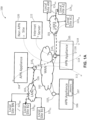
Fig. 1A illustrates an end-to-end network configured with client nodes on local area networks (LANs) coupled to a wide area network (WAN) under control of an adaptive private network (APN) showing service paths and employing improved WANop processing as further described in connection withFigs. 3-10 in accordance with an embodiment of the present invention; -
Fig. 1B illustrates an adaptive private network (APN) conduit providing two-ended service that includes integrated firewalls between a client site A and a client site B and employing improved WANop processing as further described in connection withFigs. 3-10 in accordance with an embodiment of the present invention; -
Fig. 2 illustrates an APN having an APN network control node (NCN) and sixteen APN conduits coupled to sixteen APN client sites employed in connection with improved WANop processing as described in connection withFigs. 3-10 in accordance with an embodiment of the present invention; -
Fig. 3 shows a block diagram of an embodiment of illustrative WANop processing employing a write protection cache (WPC) in accordance with the present invention; -
Fig. 4 illustrates aspects of ingress processing in accordance with the present invention; -
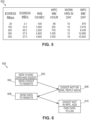
Fig. 5 shows a table with modeled appliance data for a variety of platforms utilizing WANop processing in accordance with the present invention; -
Fig. 6 illustrates data flow for previously unseen data in accordance with the present invention; -
Fig. 7 illustrates data flow for data seen for a second time in accordance with the present invention; -
Fig. 8 illustrates data flow for data seen a third and subsequent times in accordance with the present invention; -
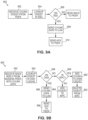
Figs. 9A and 9B (collectivelyFig. 9 ) show examples of egress peer processing in accordance with the present invention; and -
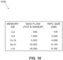
Fig. 10 shows a table of data for virtual appliance embodiments of the present invention. -
Fig. 1A illustrates an exemplary adaptive private network (APN) 100 havinglocal sites local sites LAN1 101 andLAN2 103, respectively, coupled to a wide area network (WAN) 102 under control of the APN showing service paths in accordance with an embodiment of the present invention. The APN 100 includes one or more wide area networks (WANs), such as WAN 102, APN appliances (APNAs) 104-106, WAN routers 1101-1103, and network application services as well as APN conduits between APNAs, as described in more detail below. The APN 100 is configured from a single APNA acting as a network control node (NCN) that provides a single point of control for the APN. First, however, a number of terms used herein are defined with the meaning they have when used in the context of the present invention. - An APN path is a logical connection established between two WAN links located at different geographic sites across a WAN where one WAN link sends traffic to the other WAN link. Since Paths are unidirectional entities (one sender and one receiver), two WAN links that are connected to each other have two paths between them. Each WAN link sees one path as being its transmit path and the other as the receive path. The APN path is used to send user traffic under normal circumstances.
- An APN conduit is a virtual connection between two APN nodes, also referred to as client sites, and formed by aggregating one or more APN paths and their allocated WAN link resources. A conduit service is a logical combination of one or more paths. A conduit service is typically used for enterprise site-to-site intranet traffic, utilizing the full value of the APN. With a conduit service, depending on configuration, traffic is managed across multiple WAN Links to create an end-to-end tunnel. The conduits overlay a virtual network on top of the underlying network.
- An APN appliance (APNA) is a device that contains APN client site functionality including software modules which governs its participation in an APN. A high availability (HA) site contains two APNAs, one that is active and one that is in a standby mode of operation and available to become active in place of the other APNA if required.
- A WAN link represents a physical access point to the wide area network (WAN), such as a digital subscriber line (DSL) connection or a cable modem. The distinctive characteristic of a WAN link is the bandwidth, representing the amount of data capacity available for transmission and reception. WAN links can be shared among APN conduits, and intranet and Internet network services. In the present embodiments, the APN appliances do not directly attach to WAN links. APN appliances communicate with WAN links through logical connections, such as the WAN routers 1101-1103 of
Fig. 1A . - A private WAN link provides a physical access point to non-public WAN destinations. Examples of such private WAN links include an asynchronous transfer mode (ATM) link with an ATM virtual circuit, a frame relay link with a frame relay circuit, a multiprotocol label switching (MPLS) tunnel, a virtual private network (VPN) tunnel, or a leased point-to-point line. Connectivity on a network having a private WAN link is made to a private list of destinations on the other end of the network. A public WAN link represents a physical access point to the Internet. It can be assumed that any public WAN link can establish a connection to any other public WAN link.
- A local WAN link (LWL) is an APN client site's access point to a WAN. A site A's LWL is coupled to a corresponding remote WAN link (RWL) for a site B. For a conduit between a site A and a site B, site A's local WAN links are site B's remote WAN links.
- An Internet service is used for traffic between an enterprise site and sites on the public Internet. The Internet is treated as a separate security zone. Traffic on the Internet is considered less trustworthy than conduit traffic in an APN because the Internet traffic has not been encapsulated and encrypted as is done in a conduit. Also, the Internet traffic is generally coming from an entity not under control of the enterprise that owns the trusted network.
- An intranet service is used for any portion of enterprise intranet traffic that has not been defined for transmission across a conduit. As with Internet traffic, the intranet traffic remains unencapsulated, and the APN manages bandwidth in the network by rate-limiting the intranet traffic relative to other service types during times of congestion. Note that under certain conditions, and if configured for intranet fallback on the conduit, traffic that ordinarily travels via a conduit may instead be treated as intranet traffic in order to maintain network reliability. Since conduit traffic is site-to-site, customers generally have a way to deliver this site-to-site traffic without the conduit. This unencapsulated service, called an intranet service, does not receive the benefits of the conduit. If the conduit tunnel cannot be brought up, then routes which use that conduit are ignored and this means that traffic that would have used the conduit are redirected to use an unencapsulated site-to-site transport method.
- A flow is defined by an n-tuple consisting of <IP source address, IP destination address, IP protocol number, transmission control protocol (TCP)/ user datagram protocol (UDP) source port, if the IP protocol is TCP or UDP, TCP/UDP destination port, if the IP protocol is TCP or UDP>. Depending on the context, other items could be added to the tuple including: a differentiated services code port (DSCP) tag, a routing domain, and a service identifier, and the like. Also, a flow is unidirectional. For example, if nodes A and B are communicating, there is a flow that represents traffic from A to B and a flow representing traffic from B to A.
- An APN service is a set of processing steps performed on packets that are transmitted through the APN. As illustrated in
Fig. 1A , data traffic that moves through theAPN 100 andAPN appliance 106 may require different types of services depending on where the sending and receiving stations are located. An APN service instance is a particular configured contextual instance of an APN service held in anAPN appliance memory 107 internal to theAPN appliance 106, for example. An APN service instance's memory contains, but is not limited to, context specific configuration data, statistical data, and tracking states data. For example, an APN client site may have multiple APN conduits that connect to remote APN client sites. For each APN conduit there exists a separate APN service instance for the APN conduit service type. - An APN conduit service associated with
path 112 manages network traffic packets that are transmitted through theAPN 100 from theAPN appliance 105 through router 1101, through theWAN 102, through another router 1103 to APN appliance (APNA) 104. The APN conduit service forpath 112 operates on bothAPN appliances APNA 105 and a different geographic location that has theAPNA 104 utilizing the full benefits provided by the APN conduit service for WAN resource allocation and network adaptation. An APN intranet service associated withpath 114 is used to manage the sending and receiving of data between a first geographic location that has theAPN appliance 105 and a different geographic location within anenterprise non-APN site 120 that does not have an APN appliance by way of a WAN link that is also utilized by other APN services. - In another embodiment, an APN intranet service, such as the one associated with
path 112, may be used to send and receive data to and from a different geographic location that has an APN appliance, but an administrator selectively configures the APN not to use theAPN conduit service 112 for a particular type or class of traffic. An APN Internet service associated withpath 116 is used to send and receive data between a first geographic location that has theAPNA 105 and a different geographic location that is external to an enterprise network by way of a WAN link that is also utilized by other APN services. For example, traffic using the APN Internet service may be associated with a network user accessing a publicInternet web server 122. An APN pass throughservice 118 is used to send and receive data between a first geographic location that has theAPNA 105 and alocal site 124A1 within the same first geographic location. In another embodiment, an APN pass through service may be used to send and receive data between a first geographic location that has theAPN appliance 105 and a different geographic location within an enterprise network that does not have an APN appliance and does not traverse the WAN using any WAN links associated with any other APN services. - In a further embodiment, a
path 126 has a firstlocal site 124A2 connected toLAN1 101 toAPNA 105 to WAN router 1101 through theWAN 102 to WAN router 1103 toAPNA 104 to LAN2 103 to secondlocal site 125B2.LAN1 101 andLAN2 103 are exemplary networks having a plurality of routers and routing paths which are managed and can change to improve network performance. - A conduit consists of multiple paths. A path is formed between 2 WAN links associated with the conduit. Each path in each conduit in the APN is monitored for quality of communication by collecting quality metrics such as packet loss and latency. This monitoring is done by way of control messages and is done on each path whether the path is used to transmit user traffic or not. Accordingly, no path is completely free of traffic unless it is not operational. Since all paths within a conduit are being measured whether there is user traffic through the path or not, the conduit maintains up to date per-path metrics that are used by the APN to select the best network path to transmit user data.
- A static conduit is a conduit configured in a configuration file and created at startup time of an APNA. A static conduit is not removed without changing the configuration file.
- A dynamic conduit is a conduit created between APN clients when needed and which can be removed when no longer needed. Dynamic conduits address changes in statically configured networks that are happening in real time across a network. In real time, dynamic conduits optimize network performance adapting to changing communication patterns between nodes in the network. Dynamic conduits can also be used to offload traffic from intermediate nodes experiencing congestion.
- An adaptive private network (APN) software product according to the present invention runs as a centralized management system within a virtual machine to create APN configurations and to monitor system resources, analyze system resources, and manage a configured APN in operation as addressed further herein. The APN system further allows a centralized virtual single point of control by a network control node (NCN) for a physical network in which the NCN provides system wide timing synchronization. The centralized single point of control is not limited to a central location within a network of nodes, may be at any point within the network, and may be coupled at a point that would be considered outside the boundary of a network.
-
Fig. 1B illustrates an adaptive private network (APN) conduit supporting two-endedservice 150 that includesintegrated firewalls client site A 152 and an APNclient site B 154 in accordance with an embodiment of the present invention. Each APN client site is also considered a node in the APN and contains a collection of software modules which govern its participation within the APN. The software modules for the APNclient site A 152 and the APNclient site B 154 includecontrol plane modules ingress processor modules egress processor modules software program modules Fig. 1B , the WANingress processor modules egress processor modules Firewalls - As illustrated in
Fig. 1B , APN conduit traffic, identified by bold dashedarrow paths APN client sites ingress processing module 162 of APNclient site B 154 performs the WAN ingressconduit service processing 174 prior to transmitting thetraffic 180 via theWAN 184 to the APNclient site A 152. WANegress processor module 164 of the APNclient site A 152 performs the WAN egressconduit service processing 176 prior to transmitting thetraffic 180 to the node or nodes located onLAN 186. The binding of the one APN client site's WANingress conduit processing 174 to the peer APN client site's WAN egressconduit service processing 176 constitutes anAPN conduit 188 in which traffic is actively monitored and managed across multiple WAN resources. Control programs, referred to ast2_apps - The APN is capable of using disparate asymmetric WAN links which frequently vary in behavior with respect to bandwidth, latency, jitter, packet loss and congestion over time. For example, the APN can use an asymmetric DSL WAN link that transmits data at 512 kbps upstream to the WAN and 6 Mbps from the WAN through the public network combined with a private symmetric leased circuit T1 WAN link that transmits data at 1544 kbps upstream and downstream and a cable broadband connection that transmits data at 312 kbps upstream to the WAN and 3 Mbps from the WAN to a peer having adequate aggregation bandwidth of these rates for a single transmission control protocol (TCP) file transfer session at a theoretical transmit rate of 2368 kbps and receive at 10544kbps or 10.544 Mbps. Practically, under good network behavior, the actual rate would approach 90% of these rates. If the behavior of the connection was to change, for example the paths to the DSL link were to have dramatic levels of loss, the APN would, using its high frequency performance feedback mechanism, adapt the network to avoid or mitigate the issues by using alternative resources or attempting to recover from the loss.
- In path selections, conduit paths are evaluated and the best available path is selected. Any paths currently in a path quality good state are eligible to be chosen first. If multiple paths are in a path quality good state, then an estimated end to end time is evaluated and compared for each path, and the path with the lowest end to end time is chosen. If no path is in path quality good state, then a path with the highest bandwidth path quality bad state is chosen. A "one way time" (OWT) refers to the amount of time it takes for a packet to traverse a network from source to receiver. In the context of this invention, the one way time is measured by subtracting a receive time stamp from a
WAN Egress Module 166 from the send time stamp from aWAN ingress module 160,Fig. 1B .U.S. Patent No. 8,125,907 filed on June 11, 2009 entitled "Flow-Based Adaptive Private Network with Multiple WAN-Paths" provides exemplary details of a presently preferred approach to timing and network control in an adaptive private network (APN) at col. 6, line 1-col. 19, line 27, for example. - APN path processing services are responsible for providing a means of communicating user data and control information from one APN node to another APN node across the network. In particular, user data and control information may be transmitted from the WAN
ingress processor module 160 of one APN node across the WAN and received at the WANegress processor module 166, as shown for example inFig. 1B . - A path state represents the most current condition of the network path as determined by feedback received by the WAN egress APN node's path state monitoring process. As packets are received, the sequence numbers of the packets are tracked to see if any packets were lost in transit between the WAN ingress APN node and the WAN egress APN node. A method is used to trigger path state transitions that are biased toward more tolerance for loss in the short periods of packets received with substantially less tolerance of loss over longer periods. A unique aspect of this approach is the ability to track the path's packet loss thresholds over numerous durations nearly simultaneously and continually while still maintaining low processor overhead. This aspect is obtained through the universal path tagging of conduit traffic sent across the WAN with high resolution and highly synchronized APN time stamps to enable the highly predictive estimation of transmission latency and statistical variation of latency. In tandem, a control plane modules' path state monitoring service is used to detect packet loss and optimal paths for traffic to use across the APN. The result is an ability to detect a difference between occasional incidental short term network loss and long term persistent problems.
- In a presently preferred embodiment, the APN node's software modules at a client site are stored and operate in the same physical APN appliance; however, the modules may also exist in separate physical APN appliances in alternative embodiments. The methods described in connection with the embodiments disclosed herein may be embodied directly in one or more software modules executed by a processor and memory complex such as utilized in an adaptive private network (APN) appliance (APNA), a rack mounted processing device, a personal computer, a server, or the like, having one or more central processing unit devices. The processor and memory complex, for example, may be configured to execute instructions that access data and operate on data under control of a software module program stored on a computer readable non-transitory storage medium either directly associated locally with the processor and memory complex, such as may be available through an instruction cache, or accessible through an I/O device. A software module may reside in a computer readable non-transitory storage medium which may include random access memory (RAM), flash memory, dynamic random access memory (DRAM), synchronous dynamic random access memory (SDRAM), read only memory (ROM), programmable read only memory (PROM), erasable programmable read only memory (EPROM), electrically erasable programmable read only memory (EEPROM), hard disk, a removable disk, a CD-ROM, digital video disk (DVD), other types of removable disks, or any other suitable non-transitory storage medium. A non-transitory storage medium may also be coupled to the processor and memory complex such that the hardware processor can read information from, and write information to, the storage medium over an intranet or the Internet.
- An adaptive private network node (APN client site) contains software modules supporting participation in an adaptive private network. An APN node may exist in one or more APN appliances at a location. An APN node contains a collection of software modules executed by a processor and memory complex located in the APN node which govern the APN node's participation within an APN such as
control plane modules ingress processor modules egress processor modules Fig. 1B . Thecontrol plane modules - The WAN
ingress processor module 160 may suitably be embodied as software and hardware components responsible for processing network traffic for transmission from a local area network (LAN) to a WAN. The WANegress processor module 164 may suitably be embodied as software operating on hardware components, such as a processor and memory complex that is responsible for processing network traffic for transmission from a WAN to a LAN. WAN ingress and WAN egress processor modules are discussed in further detail below. The APN client site'scontrol plane module 156 may suitably be embodied as software operating on hardware components, such as a processor and memory complex that utilizes the APN client site's WANingress processor module 160 and WANegress processor module 164 as the means for transmitting and receiving APN node to APN node control data across the WAN. - Software packages for an APN are distributed through the WAN using control packets, termed Tapplication protocol (TAP) packets, that is part of change management software or through administrative interfaces, such as downloading
software using interfaces APN client sites -
Fig. 2 illustrates anAPN 200 having an APN network control node (NCN) 202 coupled toconduit section 220 and sixteen APN conduit sections 221-236 coupled to sixteen APN client sites 204-219, respectively, in accordance with an embodiment of the present invention. As illustrated inFig. 2 , in a presently preferred embodiment,APN 200 is centrally configured. A network administrator configures theentire APN 200 through an APN configuration file that is processed by theNCN 202. TheNCN 202 then distributes the configuration settings to all client sites in theAPN 200. This method of configuring theAPN 200 is intended to provide benefits to the administrator by providing a single point of configuration to the network. It also assures configuration consistency and compatibility for all APN client sites in the network nearly simultaneously, with strict version checking. The central configuration also provides for additional configuration bandwidth optimization for the network, by doing a mapping of the APN resources and their initial allocations. Furthermore, the centralized configuration can provide information and warnings to the administrator as to the behavior of the configuration that may not be obvious or intended from the configuration, before loading the configuration onto a production network. - Each of the sites 204-219 and
primary NCN site 202 contains an APN appliance to provide APN functionality. The configuration of theAPN 200, generally provides for connectivity between a site A, such assite 205, and for a site B, such assite 208, where the connectivity from the site A's perspective is site A→LWL→"WAN"→RWL→site B. The connectivity from the site B's perspective is site B→LWL→"WAN"→RWL→site A. TheWAN 201 represents allocated WAN link resources and APN selected paths. InFig. 2 , a conduit between a site A and a site B is formed by use of theconduit sections - In one presently preferred embodiment, APN conduits exist between the NCN and, for example, sixteen APN client sites as shown in
Fig. 2 . It will be recognized that while sixteen APN sites are shown for purposes of illustration, a larger or smaller number of potential APN client sites may be suitably employed. Each APN conduit may have the unique configuration parameters tailored by an administrator for the particular needs of each geographic location associated with a particular APN. - For a definition of APN path states, a description of path processing services is provided below. Any paths currently in a path quality good state are eligible to be chosen first. If multiple paths are in a path quality good state, then an estimated end to end time is evaluated and compared for each path, and the path with the lowest end to end time is chosen. If no path is in a path quality good state, then a path in a path quality bad state with the highest bandwidth is chosen.
- The sixteen client sites 204-219 of the
exemplary APN 200 are generally located remotely from each other and may include geographically diverse client sites. A site would be defined as remote if the devices are physically in different locations such as different buildings, cities, states, time zones or countries. For example, theprimary NCN 202 may be located in a company's headquarters location in a first country with client sites 204-209 and client sites 217-219 also located in the first country. The other client sites 210-216 may be located in a second country. - As used herein, an APN appliance is a device that contains APN node functionality according to software modules, such as the
control plane modules ingress processor modules egress processor modules Fig. 1B . The sixteen client sites 204-219 are coupled by conduit sections 221-236, respectively, and the conduit sections may be connected together to provide a configurable virtual connection between two connected APN appliances at the client sites. It is noted that while sixteen client sites 204-219 are illustrated, an APN may support as many client sites as are required. - A network control point (NCP) 202 of
Fig. 2 is an administration point for theAPN 200. In one embodiment, theNCP 202 resides within an APN node. An APN control node refers to an APN node that also performs as the network control point of the APN. In another embodiment, an NCP resides in an appliance that is separate from an APN node and administers and controls the APN nodes within the APN. The NCP provides administrative and control to the APN, including but not limited to, distribution of configuration objects to APN client nodes and time synchronization to the APN. - A dynamic conduit is a conduit created between APN clients when needed and can be removed when no longer needed, based on a configured threshold. For example,
client site 205 can be configured with two local WAN links, one from a first network provider and one from a second network provider. Multiple conduits may be connected tosite 205 which may be configured to use one or both of the local WAN links. In an exemplary scenario where all of the conduits that are connected tosite 205 use both local WAN links, then when usage for either local WAN link passes the configured threshold, creation of a dynamic conduit can be triggered. - An APN traffic flow is the administrator designation for network session traffic that is identified to a particular APN flow record. APN traffic flow requirements are administrator-configured requirements that govern an intended behavior of an APN as it pertains to an APN traffic flow. For example, APN traffic flow requirements may comprise a persistent path flow requirement, a duplication flow requirement, and a reliable flow requirement.
- An APN flow record is held in the memory of an APN appliance. An APN flow record tracks a defined APN traffic flow, ensuring that the APN traffic flow's prior-configured requirements are followed. The APN flow record contains both the APN traffic flow requirements and the APN traffic flow's state. The requirements of a particular APN flow record are derived from the routes and service rules that the APN traffic flow matches. The state of APN flow record includes, but is not limited to, APN service type, APN service instance, information pertaining to the last APN path selected, current APN flow sequence number, time of last packet received, time of last packet transmitted, counts of number of packets and number of bytes processed, sets of pending packets for sequence reordering, sets of pending packets for fragmentation, and sets of historical records for packets previously processed.
- For further detail on the processing stages of WAN ingress conduit processing, see
U.S. Patent No. 8,125,907 issued February 8, 2012 entitled "Flow-Based Adaptive Private Network with Multiple WAN-Paths" for further details. - The present invention relates to aspects of improved WAN optimization (WANop) processing which is a way of improving how data traffic is handled by a WAN network. To such ends, two major tools, deduplication and compression, are employed as addressed further herein. Deduplication works by recognizing that the same bit patterns often traverse the WAN links multiple times. For example, many employees may download the same emails and files from a server in the data center when working on the same project. The present approaches allow network appliances near the WAN to cache this data and use small codes to represent the actual data. This approach reduces the amount of data that must traverse the WAN network.
- In one embodiment, the present invention introduces a write protection cache (WPC) between the WANop process and the disk cache on the SSD. The write protection cache provides a holding area, so that only data that has been seen more than once is committed to the disk cache.
- The write protection cache (WPC) provides a layer of protection over the data on the disk. Its presently described utilization attempts to avoid unnecessary writes to the drive. It accomplishes this end by only committing to disk the data (chunks) that is seen more than once. This feature addresses at least two separate issues:
- SSD disk wear: The SSD technology, although amazingly fast, has a significantly shorter life span than HDD. For example, the 128MB drive on the appliance may fail after writing only 14TB. There are financial ramifications to a drive supplier if the drive fails within an appliance warranty.
- Improved utilization of disk cache: By only writing data to the disk which has been previously recorded in the WPC, the writing of non repeating data, such as encrypted data, for example, to disk is avoided. Additionally, it is advantageous not to displace good, warm data that is frequently utilized with data that will never be seen again.
- WPC is a cache of secure hash algorithm (SHA)1 digests that have been received. They are stored in a reserved section of appliance memory. A 4GB WPC contains approximately 70 million digests, representing over 500GB of data. The digests are stored in the WPC, until a duplicate is detected. Then, the chunk, data and digest, is added to the disk cache and the entry is removed from the WPC.
- Terms used herein include: DWPD: drive writes per day; WPC: write protection cache; and WANop: a collection of techniques for increasing data transfer efficiencies across the WAN.
- As noted above, one current WANop approach writes chunks to disk on both the WAN ingress and WAN egress appliance. This approach assures that data sent in one direction may immediately be used for deduplication in the opposite direction. However, the present invention recognizes that in many cases this two way availability is unnecessary, as data tends to be unidirectional.
- In contrast, by not writing to the disk on WAN ingress as illustrated in
WANop process 300 ofFig. 3 ,WANop process 300 only learns on WAN egress. Thus, if a chunk is learned or written to disk, in one direction, that information is not shared with the reverse direction. In most cases, this approach is a very good tradeoff. If the same data flows in both directions, theWANop process 300 will quickly learn it. But, if as expected that little data is common to WAN egress and WAN ingress, then substantial process savings are recognized. - Turning to
Fig. 3 in greater detail,peer 1 330 may suitably be a WANop egress processor which processes network traffic from a WAN, such as a cloud packet I/O connection 340 to download data from cloud storage. For example, data is downloaded to a LAN, such asclient stream 348 on the LAN connected to a client device, such as a laptop. Betweencloud connection 340 andclient stream 348 data passes through a64k input buffer 341 to adecompress process 342 and therefrom to get digestdata 344 to retrieve digest and/or data as addressed further below fromWPC 310 anddisk 320. The data then proceeds through64k output buffer 346 toclient stream 348. -
Peer 2 350 may suitably be a WAN ingress processor which processes network traffic for transmission from a local area network (LAN) connected to a client device, such as a laptop, from which the client sends aclient stream 360 for transmission of data to cloud storage through WAN cloud packet input-output (I/O)connection 368. In between, the data passes through a 64k input buffer to adeduplication process 362, acompression process 364 and a64k output buffer 366. - On WAN egress, WANop's
WPC 310 stores chunk digests and compares newly arriving digests with those previously seen to identify duplicates. When a duplicate is detected as addressed further herein, the digest and chunk are written todisk cache 320. The downside of the presently described approach is that the data must be sent from the WAN ingress peer twice, as opposed to once in the previous approach as addressed in further detail herein. - To further limit disk writes,
process 400 of WAN ingress processing shown inFig. 4 will write no data to disk. Instep 402, data arrives on the LAN and is grouped into chunks instep 404. A typical chunk is between 1.5kB and 22kB, with an average of about 8kB. Instep 405, a secure hash algorithm (SHA)1 digest is calculated for the chunk and the digest is forwarded to the peer. It will be recognized that other hash algorithms may suitably be employed. In step 407, the peer responds with an ACK if it has the chunk/digest in its cache, or a NACK, if it does not have the chunk/digest. In step 408, if the response is a NACK, the chunk data is sent to the peer. As noted, for unidirectional flow, there will be no writes to the cache, WPC or SSD, on ingress. In the user interface (UI) WAN ingress statistics, an ACK is shown as a hit and a NACK is reported as a miss. - Turning to appliance modeling for egress processing, the data structure for storing the digest is 64 bytes, and the average chunk of data is 8kB. By only storing the digest, WANop's memory of previously seen data becomes approximately 128 times larger than the WPC. For example, a one megabyte WPC contains 16k digests representing 128 megabytes of chunk data.
- An appliance modeling example follows below:
- An appliance supports 100Mbps of sustained WANop throughput,
- 100 Mbps corresponds to 12.5MBps corresponding to 1,600(8kB) chunks per second; and
- WPC fill rate: 102.4kBps of WPC corresponding to 352MB/hr WPC.
- With a 100 Mbps data rate, a 3.5GB WPC provides a 10 hour memory of unique chunks representing 439GB of data. Similar data for other platforms is provided in Table 500 of
Fig. 5 . - Turning to data flow,
Fig. 6 shows aprocess 600 for processing a request for a previously unseen chunk received by the WAN ingress peer. In other words, the chunk is not in the WPC or on the disk. First, the digest is sent to the WAN egress peer instep 604. As this is a new chunk and the digest was not in its disk cache, the WAN egress peer replies with a NACK instep 606. On receiving the NACK, the WAN ingress peer sends over the chunk's data instep 608. Upon determining the digest is not in the WPC, the WAN egress peer adds the digest to the WPC and forwards the data to the LAN instep 610. -
Fig. 7 shows aprocess 700 for processing a chunk seen for the second time. As shown inFig. 7 , instep 702, when the same chunk is received by the WAN ingress peer, the digest is again sent to the WAN egress peer. The digest is determined not to be on the disk instep 704 and the WAN egress peer replies with a NACK instep 706. Instep 708, the ingress peer sends the chunk's data to the WAN egress peer. The digest for the chunk is found in the WPC as a result of it being added instep 610. The data is added to the disk and the digest is removed from the WPC instep 710. Instep 712, the data is forwarded to the LAN. -
Fig. 8 shows aprocess 800 for processing a chunk seen for the third and subsequent times. As shown inFig. 8 , when a chunk is seen for a third or subsequent time, that chunk comprising data and digest is sent to egress peer instep 804. Instep 806, the digest sent instep 804 corresponds to a chunk already stored on the disk and an ACK is sent to the ingress peer. Instep 808, the egress peer forwards the data to the LAN. -
Figs. 9A and 9B (collectivelyFig. 9 ) illustrate process flows 900 and 950, respectively. Instep 902 ofprocess 900 ofFig. 9A , a WAN egress peer receives a chunk digest from an ingress peer. Instep 904, the egress peer performs a lookup operation to determine if the received digest is stored on the disk which in a presently preferred embodiment is a semiconductor storage device (SSD). Instep 906, if the determination instep 904 is "No", then process 900 continues by sending a NACK response to the ingress peer. If the determination is "Yes" instep 906, then the chunk data is sent to the LAN instep 908 and the ACK response is sent to the ingress peer instep 910. - In
step 952 ofprocess 950 ofFig. 9B , the egress peer receives a NACK reply from ingress peer with chunk data including the digest. The egress peer proceeds instep 954 to lookup the digest in the disk cache to see if it is there. If it is determined the digest is on the disk cache instep 956, the egress peer proceeds to determine if the chunk data is stored in the WPC instep 958. If yes, instep 960, the chunk is added to the disk storage. Instep 962, the digest is deleted from the WPC and instep 966, the chunk data is sent to the LAN. Instep 968, an ACK response is sent to the ingress peer. If instep 958, the determination is "no" the digest is not in the WPC, the digest is added to the WPC instep 964. - Returning to step 956, if yes, the digest is located on the disk storage, then in
step 966, the chunk data is sent to the LAN. Instep 968, the ACK response is sent to the ingress peer. - Turning to WPC digest management, each entry in the presently preferred WPC is 64 bytes(B) and contains a chunk digest. Initially, all entries are on a free list. As digests are added to the WPC, entries move from the free list to the in use list. When the WPC gets a hit, the entry is removed from the in use list, and placed back on the free list. When a new entry is required and the free list is empty, the oldest entry on the in use list is freed and used for the new entry. Alternatively, the oldest entry of a certain size could be freed up. For example, the oldest entry or entries less than a certain size would be deleted before a similarly old entry of a larger size.
- It will be recognized that the present invention can be embodied in a virtual appliance. In this context, virtual appliances operate in the same manner as a regular appliance, but the virtual appliance must adjust its scalability and resource requirements based on the underlying virtual memory (VM) configuration. In this context, WANop memory requirement sizes are based on total memory.
- While the present invention has been disclosed in the context of various aspects of presently preferred embodiments, it will be recognized that the invention may be suitably applied to other environments consistent with the claims which follow. By way of example, while the present application discusses not storing a digest and data, a chunk, to disk cache until that chunk is seen a second time, it will be recognized that the storage operation could occur only after seeing the same chunk for a third or subsequent time, and that the number could be a user selectable parameter adapted to a particular user's experience and context. Further, the number could vary depending upon chunk size with maximum size chunks stored upon being seen for a second time and minimum size chunks being seen for a third time, for example. Other factors such as time of day, the amount of remaining available disk storage and the like could also be considered.
Claims (15)
- A wide area network, WAN, optimization method for reducing data storage, the method comprising:receiving data and a digest of the data for a first time;storing the digest in a write protect cache in response to making a determination that this is the first time the data and digest have been received;receiving the data and the digest of the data for a second time;after the step of receiving the data and the digest of the data for a second time, storing the data and the digest of the data on a main disk and removing the digest from the write protect cache in response to making a determination that this is the second time that the data and digest have been received;receiving the digest on further transfers; andaccessing the data from the main disk based on the received digest.
- The method of claim 1 wherein storing the data and a digest of the data on a main disk will only occur during WAN egress processing.
- The method of claim 1 wherein said receiving data and a digest of the data for the first time occurs in a WAN egress process.
- The method of claim 3, further comprising:receiving data arriving on a local area network by a WAN ingress process; andgrouping the data into chunks.
- The method of claim 4 further comprising:
calculating a digest for each chunk by the WAN ingress process. - The method of claim 5 further comprising:
sending a first digest for a first chunk to an egress process. - The method of claim 6 further comprising:responding with an acknowledgement response, ACK, by the egress process if the egress process has the first chunk stored in the main disk; andresponding with a non-acknowledgement response, NACK, by the egress process if the egress process does not have the first chunk stored in the main disk.
- The method of claim 7 further comprising:
sending the first chunk of data to the egress process if the response is a NACK. - A wide area network, WAN, optimization apparatus for reducing data storage, comprising:means for receiving data and a digest of the data for a first time;means for storing the digest in a write protect cache in response to making a determination that this is the first time the data and digest have been received;means for receiving the data and the digest of the data for a second time;means for, after receiving the data and the digest of the data for a second time, storing the data and the digest of the data on a main disk and removing the digest from the write protect cache in response to making a determination that this is the second time that the data and digest have been received;means for receiving the digest on further transfers; andmeans for accessing the data from the main disk based on the received digest.
- The apparatus of claim 9 wherein said means for receiving data and a digest of the data for the first time comprises a WAN egress processor.
- The apparatus of claim 10 wherein storing the data and a digest of the data on a main disk will only occur during WAN egress processing.
- The apparatus of claim 10, further comprising:
a WAN ingress processor receiving data arriving on a local area network, the WAN ingress processor grouping the data into chunks. - The apparatus of claim 12 further comprising:
the WAN ingress processor calculating a digest for each chunk. - The apparatus of claim 13 further comprising:
the WAN ingress processor sending a first digest for a first chunk to the egress processor. - The apparatus of claim 14 further comprising:The egress processor responding with an acknowledgement response, ACK, if the egress processor has the first chunk stored in the main disk; the egress processor responding with a non-acknowledgement response ,NACK, if the egress process does not have the first chunk stored in the main disk; andmeans for sending the first chunk of data if the first response is a NACK.
Applications Claiming Priority (2)
| Application Number | Priority Date | Filing Date | Title |
|---|---|---|---|
| US201762589163P | 2017-11-21 | 2017-11-21 | |
| PCT/US2018/062133 WO2019104098A1 (en) | 2017-11-21 | 2018-11-20 | Intelligent write protection cache (iwpc) in an adaptive private network (apn) |
Publications (3)
| Publication Number | Publication Date |
|---|---|
| EP3714371A1 EP3714371A1 (en) | 2020-09-30 |
| EP3714371A4 EP3714371A4 (en) | 2021-07-28 |
| EP3714371B1 true EP3714371B1 (en) | 2025-04-16 |
Family
ID=66532406
Family Applications (1)
| Application Number | Title | Priority Date | Filing Date |
|---|---|---|---|
| EP18881156.6A Active EP3714371B1 (en) | 2017-11-21 | 2018-11-20 | Intelligent write protection cache (iwpc) in an adaptive private network (apn) |
Country Status (5)
| Country | Link |
|---|---|
| US (1) | US10789380B2 (en) |
| EP (1) | EP3714371B1 (en) |
| JP (1) | JP7309738B2 (en) |
| CN (1) | CN111316254B (en) |
| WO (1) | WO2019104098A1 (en) |
Families Citing this family (2)
| Publication number | Priority date | Publication date | Assignee | Title |
|---|---|---|---|---|
| JP7309738B2 (en) | 2017-11-21 | 2023-07-18 | タラリ・ネットワークス・インコーポレイテッド | Intelligent Write Protection Cache (IWPC) in Adaptive Private Networks (APNs) |
| US12549372B2 (en) | 2020-06-03 | 2026-02-10 | Alibaba Group Holding Limited | Network access method, user equipment, network entity, and storage medium |
Family Cites Families (14)
| Publication number | Priority date | Publication date | Assignee | Title |
|---|---|---|---|---|
| US7313614B2 (en) * | 2000-11-02 | 2007-12-25 | Sun Microsystems, Inc. | Switching system |
| US6782416B2 (en) * | 2001-01-12 | 2004-08-24 | Hewlett-Packard Development Company, L.P. | Distributed and geographically dispersed quorum resource disks |
| JP2007065928A (en) * | 2005-08-30 | 2007-03-15 | Toshiba Corp | Information storage medium, information processing method, information transfer method, information reproduction method, information reproduction device, information recording method, information recording device, and program |
| CN101228523B (en) * | 2005-04-25 | 2012-06-06 | 网络装置公司 | System and method for caching network file systems |
| US8046422B2 (en) * | 2006-08-21 | 2011-10-25 | Netapp, Inc. | Automatic load spreading in a clustered network storage system |
| US7840537B2 (en) * | 2006-12-22 | 2010-11-23 | Commvault Systems, Inc. | System and method for storing redundant information |
| US8125907B2 (en) * | 2008-06-12 | 2012-02-28 | Talari Networks Incorporated | Flow-based adaptive private network with multiple WAN-paths |
| US10447543B2 (en) | 2009-06-11 | 2019-10-15 | Talari Networks Incorporated | Adaptive private network (APN) bandwith enhancements |
| US8452846B2 (en) | 2010-08-12 | 2013-05-28 | Talari Networks Incorporated | Adaptive private network asynchronous distributed shared memory services |
| US10476765B2 (en) * | 2009-06-11 | 2019-11-12 | Talari Networks Incorporated | Methods and apparatus for providing adaptive private network centralized management system discovery processes |
| US9501365B2 (en) | 2009-12-28 | 2016-11-22 | Netapp, Inc. | Cloud-based disaster recovery of backup data and metadata |
| US9144082B2 (en) * | 2012-06-13 | 2015-09-22 | All Purpose Networks LLC | Locating and tracking user equipment in the RF beam areas of an LTE wireless system employing agile beam forming techniques |
| US9300748B2 (en) * | 2013-01-16 | 2016-03-29 | Cisco Technology, Inc. | Method for optimizing WAN traffic with efficient indexing scheme |
| JP7309738B2 (en) | 2017-11-21 | 2023-07-18 | タラリ・ネットワークス・インコーポレイテッド | Intelligent Write Protection Cache (IWPC) in Adaptive Private Networks (APNs) |
-
2018
- 2018-11-20 JP JP2020546289A patent/JP7309738B2/en active Active
- 2018-11-20 US US16/196,358 patent/US10789380B2/en active Active
- 2018-11-20 CN CN201880072247.0A patent/CN111316254B/en active Active
- 2018-11-20 WO PCT/US2018/062133 patent/WO2019104098A1/en not_active Ceased
- 2018-11-20 EP EP18881156.6A patent/EP3714371B1/en active Active
Also Published As
| Publication number | Publication date |
|---|---|
| US20190156048A1 (en) | 2019-05-23 |
| CN111316254A (en) | 2020-06-19 |
| US10789380B2 (en) | 2020-09-29 |
| WO2019104098A1 (en) | 2019-05-31 |
| JP7309738B2 (en) | 2023-07-18 |
| CN111316254B (en) | 2023-05-05 |
| EP3714371A1 (en) | 2020-09-30 |
| EP3714371A4 (en) | 2021-07-28 |
| JP2021504858A (en) | 2021-02-15 |
Similar Documents
| Publication | Publication Date | Title |
|---|---|---|
| US10348571B2 (en) | Methods and apparatus for accessing dynamic routing information from networks coupled to a wide area network (WAN) to determine optimized end-to-end routing paths | |
| Anand et al. | SmartRE: an architecture for coordinated network-wide redundancy elimination | |
| JP5944537B2 (en) | Communication path management method | |
| US20160112544A1 (en) | Transparent Proxy Architecture for Multi-Path Data Connections | |
| KR20030019900A (en) | Parallel information delivery method based on peer-to-peer enabled distributed computing technology and the system thereof | |
| JP2007527170A (en) | System and method for parallel communication | |
| JP2008526132A (en) | Bulk data transfer | |
| CN113472646A (en) | Data transmission method, node, network manager and system | |
| WO2021098425A1 (en) | Qos policy method, device, and computing device for service configuration | |
| US10789380B2 (en) | Intelligent write protection cache (IWPC) in an adaptive private network (APN) | |
| JPWO2013146808A1 (en) | Computer system and communication path changing method | |
| CN108156040A (en) | A kind of central control node in distribution cloud storage system | |
| US8886705B1 (en) | Goal-oriented storage management for a distributed data storage network | |
| CN120321320A (en) | Address resolution protocol message sending method, device, computer equipment, readable storage medium and program product | |
| US12425350B2 (en) | Packet fragmentation prevention in an SDWAN router | |
| CN108390899B (en) | Software defined network-based method for content collaboration of two-layer switch | |
| Matsuzono et al. | Content request handling for application-oriented transport control | |
| JP2007041899A (en) | Content distribution apparatus, content distribution network, and content distribution method | |
| KR20040076660A (en) | Parallel information delivery method based on peer-to-peer enabled distributed computing technology and the system thereof | |
| JP6593886B2 (en) | High-speed upload system, retransmission control method thereof, and program | |
| US12562993B2 (en) | Packet fragmentation prevention in an SDWAN router | |
| Renganathan et al. | Rethinking Networking for" Five Computers" | |
| US12445348B2 (en) | Electronic system for proactive resiliency, redundancy and security remediation across a network based on dynamic analysis of technology applications | |
| Zhang et al. | MDVAC: A multi-dimensional value-aware caching strategy for information-centric networks | |
| Dey et al. | CAR: Cloud-assisted routing |
Legal Events
| Date | Code | Title | Description |
|---|---|---|---|
| STAA | Information on the status of an ep patent application or granted ep patent |
Free format text: STATUS: THE INTERNATIONAL PUBLICATION HAS BEEN MADE |
|
| PUAI | Public reference made under article 153(3) epc to a published international application that has entered the european phase |
Free format text: ORIGINAL CODE: 0009012 |
|
| STAA | Information on the status of an ep patent application or granted ep patent |
Free format text: STATUS: REQUEST FOR EXAMINATION WAS MADE |
|
| 17P | Request for examination filed |
Effective date: 20200326 |
|
| AK | Designated contracting states |
Kind code of ref document: A1 Designated state(s): AL AT BE BG CH CY CZ DE DK EE ES FI FR GB GR HR HU IE IS IT LI LT LU LV MC MK MT NL NO PL PT RO RS SE SI SK SM TR |
|
| AX | Request for extension of the european patent |
Extension state: BA ME |
|
| DAV | Request for validation of the european patent (deleted) | ||
| DAX | Request for extension of the european patent (deleted) | ||
| A4 | Supplementary search report drawn up and despatched |
Effective date: 20210629 |
|
| RIC1 | Information provided on ipc code assigned before grant |
Ipc: G06F 15/16 20060101AFI20210623BHEP Ipc: H04L 12/26 20060101ALI20210623BHEP Ipc: H04L 12/28 20060101ALI20210623BHEP Ipc: H04L 12/803 20130101ALI20210623BHEP Ipc: H04L 12/863 20130101ALI20210623BHEP Ipc: H04L 12/701 20130101ALI20210623BHEP Ipc: H04L 29/08 20060101ALI20210623BHEP Ipc: H04L 9/32 20060101ALI20210623BHEP Ipc: G06F 21/62 20130101ALI20210623BHEP |
|
| P01 | Opt-out of the competence of the unified patent court (upc) registered |
Effective date: 20230525 |
|
| STAA | Information on the status of an ep patent application or granted ep patent |
Free format text: STATUS: EXAMINATION IS IN PROGRESS |
|
| 17Q | First examination report despatched |
Effective date: 20231016 |
|
| GRAP | Despatch of communication of intention to grant a patent |
Free format text: ORIGINAL CODE: EPIDOSNIGR1 |
|
| STAA | Information on the status of an ep patent application or granted ep patent |
Free format text: STATUS: GRANT OF PATENT IS INTENDED |
|
| RIC1 | Information provided on ipc code assigned before grant |
Ipc: H04L 67/568 20220101ALI20241029BHEP Ipc: H04L 45/00 20220101ALI20241029BHEP Ipc: G06F 21/62 20130101ALI20241029BHEP Ipc: H04L 9/32 20060101ALI20241029BHEP Ipc: H04L 12/28 20060101ALI20241029BHEP Ipc: G06F 15/16 20060101AFI20241029BHEP |
|
| INTG | Intention to grant announced |
Effective date: 20241111 |
|
| GRAS | Grant fee paid |
Free format text: ORIGINAL CODE: EPIDOSNIGR3 |
|
| GRAA | (expected) grant |
Free format text: ORIGINAL CODE: 0009210 |
|
| STAA | Information on the status of an ep patent application or granted ep patent |
Free format text: STATUS: THE PATENT HAS BEEN GRANTED |
|
| AK | Designated contracting states |
Kind code of ref document: B1 Designated state(s): AL AT BE BG CH CY CZ DE DK EE ES FI FR GB GR HR HU IE IS IT LI LT LU LV MC MK MT NL NO PL PT RO RS SE SI SK SM TR |
|
| REG | Reference to a national code |
Ref country code: GB Ref legal event code: FG4D |
|
| REG | Reference to a national code |
Ref country code: CH Ref legal event code: EP |
|
| REG | Reference to a national code |
Ref country code: IE Ref legal event code: FG4D |
|
| REG | Reference to a national code |
Ref country code: DE Ref legal event code: R096 Ref document number: 602018081206 Country of ref document: DE |
|
| REG | Reference to a national code |
Ref country code: NL Ref legal event code: MP Effective date: 20250416 |
|
| PG25 | Lapsed in a contracting state [announced via postgrant information from national office to epo] |
Ref country code: NL Free format text: LAPSE BECAUSE OF FAILURE TO SUBMIT A TRANSLATION OF THE DESCRIPTION OR TO PAY THE FEE WITHIN THE PRESCRIBED TIME-LIMIT Effective date: 20250416 |
|
| REG | Reference to a national code |
Ref country code: AT Ref legal event code: MK05 Ref document number: 1786225 Country of ref document: AT Kind code of ref document: T Effective date: 20250416 |
|
| PG25 | Lapsed in a contracting state [announced via postgrant information from national office to epo] |
Ref country code: PT Free format text: LAPSE BECAUSE OF FAILURE TO SUBMIT A TRANSLATION OF THE DESCRIPTION OR TO PAY THE FEE WITHIN THE PRESCRIBED TIME-LIMIT Effective date: 20250818 Ref country code: ES Free format text: LAPSE BECAUSE OF FAILURE TO SUBMIT A TRANSLATION OF THE DESCRIPTION OR TO PAY THE FEE WITHIN THE PRESCRIBED TIME-LIMIT Effective date: 20250416 Ref country code: FI Free format text: LAPSE BECAUSE OF FAILURE TO SUBMIT A TRANSLATION OF THE DESCRIPTION OR TO PAY THE FEE WITHIN THE PRESCRIBED TIME-LIMIT Effective date: 20250416 |
|
| REG | Reference to a national code |
Ref country code: LT Ref legal event code: MG9D |
|
| PG25 | Lapsed in a contracting state [announced via postgrant information from national office to epo] |
Ref country code: NO Free format text: LAPSE BECAUSE OF FAILURE TO SUBMIT A TRANSLATION OF THE DESCRIPTION OR TO PAY THE FEE WITHIN THE PRESCRIBED TIME-LIMIT Effective date: 20250716 Ref country code: GR Free format text: LAPSE BECAUSE OF FAILURE TO SUBMIT A TRANSLATION OF THE DESCRIPTION OR TO PAY THE FEE WITHIN THE PRESCRIBED TIME-LIMIT Effective date: 20250717 |
|
| PG25 | Lapsed in a contracting state [announced via postgrant information from national office to epo] |
Ref country code: PL Free format text: LAPSE BECAUSE OF FAILURE TO SUBMIT A TRANSLATION OF THE DESCRIPTION OR TO PAY THE FEE WITHIN THE PRESCRIBED TIME-LIMIT Effective date: 20250416 |
|
| PG25 | Lapsed in a contracting state [announced via postgrant information from national office to epo] |
Ref country code: BG Free format text: LAPSE BECAUSE OF FAILURE TO SUBMIT A TRANSLATION OF THE DESCRIPTION OR TO PAY THE FEE WITHIN THE PRESCRIBED TIME-LIMIT Effective date: 20250416 |
|
| PG25 | Lapsed in a contracting state [announced via postgrant information from national office to epo] |
Ref country code: HR Free format text: LAPSE BECAUSE OF FAILURE TO SUBMIT A TRANSLATION OF THE DESCRIPTION OR TO PAY THE FEE WITHIN THE PRESCRIBED TIME-LIMIT Effective date: 20250416 |
|
| PG25 | Lapsed in a contracting state [announced via postgrant information from national office to epo] |
Ref country code: AT Free format text: LAPSE BECAUSE OF FAILURE TO SUBMIT A TRANSLATION OF THE DESCRIPTION OR TO PAY THE FEE WITHIN THE PRESCRIBED TIME-LIMIT Effective date: 20250416 |
|
| PG25 | Lapsed in a contracting state [announced via postgrant information from national office to epo] |
Ref country code: RS Free format text: LAPSE BECAUSE OF FAILURE TO SUBMIT A TRANSLATION OF THE DESCRIPTION OR TO PAY THE FEE WITHIN THE PRESCRIBED TIME-LIMIT Effective date: 20250716 |
|
| PG25 | Lapsed in a contracting state [announced via postgrant information from national office to epo] |
Ref country code: IS Free format text: LAPSE BECAUSE OF FAILURE TO SUBMIT A TRANSLATION OF THE DESCRIPTION OR TO PAY THE FEE WITHIN THE PRESCRIBED TIME-LIMIT Effective date: 20250816 |
|
| PG25 | Lapsed in a contracting state [announced via postgrant information from national office to epo] |
Ref country code: LV Free format text: LAPSE BECAUSE OF FAILURE TO SUBMIT A TRANSLATION OF THE DESCRIPTION OR TO PAY THE FEE WITHIN THE PRESCRIBED TIME-LIMIT Effective date: 20250416 |
|
| PGFP | Annual fee paid to national office [announced via postgrant information from national office to epo] |
Ref country code: DE Payment date: 20250930 Year of fee payment: 8 |
|
| PGFP | Annual fee paid to national office [announced via postgrant information from national office to epo] |
Ref country code: GB Payment date: 20251001 Year of fee payment: 8 |
|
| PG25 | Lapsed in a contracting state [announced via postgrant information from national office to epo] |
Ref country code: DK Free format text: LAPSE BECAUSE OF FAILURE TO SUBMIT A TRANSLATION OF THE DESCRIPTION OR TO PAY THE FEE WITHIN THE PRESCRIBED TIME-LIMIT Effective date: 20250416 Ref country code: SM Free format text: LAPSE BECAUSE OF FAILURE TO SUBMIT A TRANSLATION OF THE DESCRIPTION OR TO PAY THE FEE WITHIN THE PRESCRIBED TIME-LIMIT Effective date: 20250416 |
|
| REG | Reference to a national code |
Ref country code: DE Ref legal event code: R097 Ref document number: 602018081206 Country of ref document: DE |
|
| PG25 | Lapsed in a contracting state [announced via postgrant information from national office to epo] |
Ref country code: CZ Free format text: LAPSE BECAUSE OF FAILURE TO SUBMIT A TRANSLATION OF THE DESCRIPTION OR TO PAY THE FEE WITHIN THE PRESCRIBED TIME-LIMIT Effective date: 20250416 |
|
| PG25 | Lapsed in a contracting state [announced via postgrant information from national office to epo] |
Ref country code: EE Free format text: LAPSE BECAUSE OF FAILURE TO SUBMIT A TRANSLATION OF THE DESCRIPTION OR TO PAY THE FEE WITHIN THE PRESCRIBED TIME-LIMIT Effective date: 20250416 |
|
| PG25 | Lapsed in a contracting state [announced via postgrant information from national office to epo] |
Ref country code: SK Free format text: LAPSE BECAUSE OF FAILURE TO SUBMIT A TRANSLATION OF THE DESCRIPTION OR TO PAY THE FEE WITHIN THE PRESCRIBED TIME-LIMIT Effective date: 20250416 Ref country code: RO Free format text: LAPSE BECAUSE OF FAILURE TO SUBMIT A TRANSLATION OF THE DESCRIPTION OR TO PAY THE FEE WITHIN THE PRESCRIBED TIME-LIMIT Effective date: 20250416 |
|
| PG25 | Lapsed in a contracting state [announced via postgrant information from national office to epo] |
Ref country code: IT Free format text: LAPSE BECAUSE OF FAILURE TO SUBMIT A TRANSLATION OF THE DESCRIPTION OR TO PAY THE FEE WITHIN THE PRESCRIBED TIME-LIMIT Effective date: 20250416 |
|
| PLBE | No opposition filed within time limit |
Free format text: ORIGINAL CODE: 0009261 |
|
| STAA | Information on the status of an ep patent application or granted ep patent |
Free format text: STATUS: NO OPPOSITION FILED WITHIN TIME LIMIT |
|
| REG | Reference to a national code |
Ref country code: CH Ref legal event code: L10 Free format text: ST27 STATUS EVENT CODE: U-0-0-L10-L00 (AS PROVIDED BY THE NATIONAL OFFICE) Effective date: 20260225 |
|
| 26N | No opposition filed |
Effective date: 20260119 |