EP3714147B1 - Micro gas turbine designed to limit heat losses therefrom - Google Patents
Micro gas turbine designed to limit heat losses therefrom Download PDFInfo
- Publication number
- EP3714147B1 EP3714147B1 EP18840082.4A EP18840082A EP3714147B1 EP 3714147 B1 EP3714147 B1 EP 3714147B1 EP 18840082 A EP18840082 A EP 18840082A EP 3714147 B1 EP3714147 B1 EP 3714147B1
- Authority
- EP
- European Patent Office
- Prior art keywords
- gas turbine
- micro gas
- compressor
- turbine
- cabinet
- Prior art date
- Legal status (The legal status is an assumption and is not a legal conclusion. Google has not performed a legal analysis and makes no representation as to the accuracy of the status listed.)
- Active
Links
Images
Classifications
-
- F—MECHANICAL ENGINEERING; LIGHTING; HEATING; WEAPONS; BLASTING
- F01—MACHINES OR ENGINES IN GENERAL; ENGINE PLANTS IN GENERAL; STEAM ENGINES
- F01D—NON-POSITIVE DISPLACEMENT MACHINES OR ENGINES, e.g. STEAM TURBINES
- F01D17/00—Regulating or controlling by varying flow
- F01D17/10—Final actuators
- F01D17/12—Final actuators arranged in stator parts
-
- F—MECHANICAL ENGINEERING; LIGHTING; HEATING; WEAPONS; BLASTING
- F01—MACHINES OR ENGINES IN GENERAL; ENGINE PLANTS IN GENERAL; STEAM ENGINES
- F01D—NON-POSITIVE DISPLACEMENT MACHINES OR ENGINES, e.g. STEAM TURBINES
- F01D15/00—Adaptations of machines or engines for special use; Combinations of engines with devices driven thereby
- F01D15/10—Adaptations for driving, or combinations with, electric generators
-
- F—MECHANICAL ENGINEERING; LIGHTING; HEATING; WEAPONS; BLASTING
- F01—MACHINES OR ENGINES IN GENERAL; ENGINE PLANTS IN GENERAL; STEAM ENGINES
- F01D—NON-POSITIVE DISPLACEMENT MACHINES OR ENGINES, e.g. STEAM TURBINES
- F01D17/00—Regulating or controlling by varying flow
- F01D17/10—Final actuators
- F01D17/12—Final actuators arranged in stator parts
- F01D17/14—Final actuators arranged in stator parts varying effective cross-sectional area of nozzles or guide conduits
- F01D17/141—Final actuators arranged in stator parts varying effective cross-sectional area of nozzles or guide conduits by means of shiftable members or valves obturating part of the flow path
- F01D17/145—Final actuators arranged in stator parts varying effective cross-sectional area of nozzles or guide conduits by means of shiftable members or valves obturating part of the flow path by means of valves, e.g. for steam turbines
-
- F—MECHANICAL ENGINEERING; LIGHTING; HEATING; WEAPONS; BLASTING
- F02—COMBUSTION ENGINES; HOT-GAS OR COMBUSTION-PRODUCT ENGINE PLANTS
- F02C—GAS-TURBINE PLANTS; AIR INTAKES FOR JET-PROPULSION PLANTS; CONTROLLING FUEL SUPPLY IN AIR-BREATHING JET-PROPULSION PLANTS
- F02C3/00—Gas-turbine plants characterised by the use of combustion products as the working fluid
- F02C3/34—Gas-turbine plants characterised by the use of combustion products as the working fluid with recycling of part of the working fluid, i.e. semi-closed cycles with combustion products in the closed part of the cycle
-
- F—MECHANICAL ENGINEERING; LIGHTING; HEATING; WEAPONS; BLASTING
- F02—COMBUSTION ENGINES; HOT-GAS OR COMBUSTION-PRODUCT ENGINE PLANTS
- F02C—GAS-TURBINE PLANTS; AIR INTAKES FOR JET-PROPULSION PLANTS; CONTROLLING FUEL SUPPLY IN AIR-BREATHING JET-PROPULSION PLANTS
- F02C9/00—Controlling gas-turbine plants; Controlling fuel supply in air- breathing jet-propulsion plants
- F02C9/16—Control of working fluid flow
-
- F—MECHANICAL ENGINEERING; LIGHTING; HEATING; WEAPONS; BLASTING
- F02—COMBUSTION ENGINES; HOT-GAS OR COMBUSTION-PRODUCT ENGINE PLANTS
- F02C—GAS-TURBINE PLANTS; AIR INTAKES FOR JET-PROPULSION PLANTS; CONTROLLING FUEL SUPPLY IN AIR-BREATHING JET-PROPULSION PLANTS
- F02C9/00—Controlling gas-turbine plants; Controlling fuel supply in air- breathing jet-propulsion plants
- F02C9/16—Control of working fluid flow
- F02C9/24—Control of the pressure level in closed cycles
-
- F—MECHANICAL ENGINEERING; LIGHTING; HEATING; WEAPONS; BLASTING
- F05—INDEXING SCHEMES RELATING TO ENGINES OR PUMPS IN VARIOUS SUBCLASSES OF CLASSES F01-F04
- F05D—INDEXING SCHEME FOR ASPECTS RELATING TO NON-POSITIVE-DISPLACEMENT MACHINES OR ENGINES, GAS-TURBINES OR JET-PROPULSION PLANTS
- F05D2220/00—Application
- F05D2220/60—Application making use of surplus or waste energy
- F05D2220/64—Application making use of surplus or waste energy for domestic central heating or production of electricity
-
- F—MECHANICAL ENGINEERING; LIGHTING; HEATING; WEAPONS; BLASTING
- F05—INDEXING SCHEMES RELATING TO ENGINES OR PUMPS IN VARIOUS SUBCLASSES OF CLASSES F01-F04
- F05D—INDEXING SCHEME FOR ASPECTS RELATING TO NON-POSITIVE-DISPLACEMENT MACHINES OR ENGINES, GAS-TURBINES OR JET-PROPULSION PLANTS
- F05D2250/00—Geometry
- F05D2250/80—Size or power range of the machines
- F05D2250/82—Micromachines
-
- F—MECHANICAL ENGINEERING; LIGHTING; HEATING; WEAPONS; BLASTING
- F05—INDEXING SCHEMES RELATING TO ENGINES OR PUMPS IN VARIOUS SUBCLASSES OF CLASSES F01-F04
- F05D—INDEXING SCHEME FOR ASPECTS RELATING TO NON-POSITIVE-DISPLACEMENT MACHINES OR ENGINES, GAS-TURBINES OR JET-PROPULSION PLANTS
- F05D2260/00—Function
- F05D2260/60—Fluid transfer
- F05D2260/608—Aeration, ventilation, dehumidification or moisture removal of closed spaces
-
- F—MECHANICAL ENGINEERING; LIGHTING; HEATING; WEAPONS; BLASTING
- F05—INDEXING SCHEMES RELATING TO ENGINES OR PUMPS IN VARIOUS SUBCLASSES OF CLASSES F01-F04
- F05D—INDEXING SCHEME FOR ASPECTS RELATING TO NON-POSITIVE-DISPLACEMENT MACHINES OR ENGINES, GAS-TURBINES OR JET-PROPULSION PLANTS
- F05D2270/00—Control
- F05D2270/01—Purpose of the control system
- F05D2270/02—Purpose of the control system to control rotational speed (n)
-
- F—MECHANICAL ENGINEERING; LIGHTING; HEATING; WEAPONS; BLASTING
- F05—INDEXING SCHEMES RELATING TO ENGINES OR PUMPS IN VARIOUS SUBCLASSES OF CLASSES F01-F04
- F05D—INDEXING SCHEME FOR ASPECTS RELATING TO NON-POSITIVE-DISPLACEMENT MACHINES OR ENGINES, GAS-TURBINES OR JET-PROPULSION PLANTS
- F05D2270/00—Control
- F05D2270/30—Control parameters, e.g. input parameters
- F05D2270/335—Output power or torque
-
- Y—GENERAL TAGGING OF NEW TECHNOLOGICAL DEVELOPMENTS; GENERAL TAGGING OF CROSS-SECTIONAL TECHNOLOGIES SPANNING OVER SEVERAL SECTIONS OF THE IPC; TECHNICAL SUBJECTS COVERED BY FORMER USPC CROSS-REFERENCE ART COLLECTIONS [XRACs] AND DIGESTS
- Y02—TECHNOLOGIES OR APPLICATIONS FOR MITIGATION OR ADAPTATION AGAINST CLIMATE CHANGE
- Y02E—REDUCTION OF GREENHOUSE GAS [GHG] EMISSIONS, RELATED TO ENERGY GENERATION, TRANSMISSION OR DISTRIBUTION
- Y02E20/00—Combustion technologies with mitigation potential
- Y02E20/14—Combined heat and power generation [CHP]
Definitions
- the invention relates to a micro gas turbine as defined in claim 1 and comprising, inter alia, a compressor designed to take in and pressurize gas, a combustor designed to take in pressurized gas from the compressor and to generate hot gas on the basis of fuel combustion, a turbine designed to take in and expand hot gas generated by the combustor, a generator mechanically coupled to the turbine and designed to generate electric power on the basis of mechanical power, and a controller designed to control operation of the micro gas turbine.
- the invention is in the field of gas turbines, particularly micro gas turbines.
- a possible application of micro gas turbines is an application for Combined Heat & Power (CHP), which does not alter the fact that other applications are feasible as well.
- CHP Combined Heat & Power
- Micro gas turbines and/or micro gas turbine based CHP systems may be used instead of conventional boilers in large houses, offices, plants, schools, stores etc., to mention one example, or may be used in hybrid electric vehicles so as to extend the range of such vehicles, to mention another example.
- micro gas turbines are known for high reliability, low maintenance demand and low noise level, combined with high electric efficiency, low weight and low emissions.
- a micro gas turbine typically comprises a compressor, a combustor and a turbine.
- ambient air is drawn in and pressurized by the compressor.
- the compressed air is supplied to a combustor generating hot gas on the basis of fuel combustion.
- recuperator in a micro gas turbine, which in that case serves for pre-heating the air before being supplied to the combustor.
- the hot pressurized gas is supplied to the turbine where it expands and thereby provides mechanical power for both the compressor and a generator which is mechanically coupled to the turbine.
- the mechanical power of the generator is used to generate electric power as a first type of output from the micro gas turbine.
- the micro gas turbine is equipped with a suitable grid converter.
- the expanded gas i.e. the exhaust gas from the turbine
- a micro gas turbine it is possible for a micro gas turbine to comprise a gas-to-liquid heat exchanger, which in that case may be used for heating water, for example, so that hot water is obtained as a second type of output from the micro gas turbine.
- ambient air from an air heating system can be heated by using an air handler, in case forced air heating is used in a building, as is often the case in North America.
- the total efficiency of the micro gas turbine i.e. the combination of electric efficiency and thermal efficiency, is an important characteristic of the micro gas turbine that is preferably kept as high as possible under all circumstances.
- a certain operative output value of the electric power is taken into account.
- such operative output value may be chosen by taking into account a maximum allowable electric current value at the grid inverter, for example, or to another operative limit of one or more components of the micro gas turbine.
- the design of the micro gas turbine is optimized in view of the operative output value. This means that in order to realize the highest overall efficiency during actual operation of the micro gas turbine, it is advantageous to ensure that the micro gas turbine is in a mode in which the operative output value of the electric power is actually realized.
- the first effect can be understood on the basis of the general fact that compressing cold air requires less energy than compressing air of a higher temperature. Also, the operative output value of the electric power is realized at a lower rotational speed of an assembly of the compressor, the turbine and the generator, which will hereinafter be referred to as rotating assembly, as a result of which the volume of air used in the micro gas turbine is reduced and less energy is needed for heating.
- the second effect can be understood on the basis of the fact that a difference between the temperatures of inlet gas and outlet gas of the micro gas turbine is larger, so that the amount of thermal energy that is lost through an exhaust of the micro gas turbine is increased.
- hot gas as obtained during operation of the micro gas turbine is used for the purpose of improving thermal efficiency and/or thermal power output of the micro gas turbine.
- the fact is that hot gas is available during operation of the micro gas turbine, and at least a part of the total quantity of hot gas can be used for the purpose of causing a temperature of inlet gas of the compressor to rise.
- an actual value related to output electric power of the micro gas turbine such as an actual value of the output electric current or an actual value of the electric efficiency, is below a predetermined operative value. If this appears to be the case, an increase of a rotational speed of the turbine and the generator is realized.
- the controller is further configured to repeatedly perform a subsequent process once the rotational speed of the turbine and the generator has reached the predetermined maximum value, particularly a process comprising steps of checking an actual value related to output electric power of the micro gas turbine, and, when it is found that the actual value related to the output electric power is lower than the predetermined operative value, decreasing the extent to which hot gas is allowed to flow to the compressor until the predetermined operative value related to output electric power is achieved.
- a subsequent process once the rotational speed of the turbine and the generator has reached the predetermined maximum value, particularly a process comprising steps of checking an actual value related to output electric power of the micro gas turbine, and, when it is found that the actual value related to the output electric power is lower than the predetermined operative value, decreasing the extent to which hot gas is allowed to flow to the compressor until the predetermined operative value related to output electric power is achieved.
- the supply of hot gas to the compressor is varied for that purpose.
- the desired outcome of the controlling process remains the same, namely operating the micro gas turbine so that the rotational speed of the rotating assembly and the output electric power are at, or as near as possible to, values to which the design of the micro gas turbine is optimized as explained earlier.
- the check of the actual value related to the output electric power against the predetermined operative value can be performed in successive rounds so that a stepwise decrease of the supply of hot gas to the compressor can be realized in the process of approximating the predetermined operative value related to the output electric power and thermal losses can be kept to a minimum level under the circumstances.
- the controller is configured to perform the repeated step of checking an actual value related to output electric power at a predetermined time interval.
- the micro gas turbine comprises a valve mechanism which is associated with an inlet path to the compressor, the valve mechanism being controllable by the controller to open the inlet path of the compressor to hot gas as obtained during operation of the micro gas turbine.
- hot gas is available during operation of the micro gas turbine.
- hot gas can be retrieved from a cabinet of the micro gas turbine in which the compressor, the combustor, the turbine and more components of the micro gas turbine are accommodated, assuming that the micro gas turbine further comprises a purging mechanism designed to realize purging of the cabinet's interior by supplying air to the cabinet's interior.
- the valve mechanism it is practical for the valve mechanism to be controllable by the controller to open the inlet path of the compressor to the cabinet's interior for enabling the compressor to take in air supplied by the purging mechanism to the cabinet's interior.
- the cabinet's interior is hot during operation of the micro gas turbine due to operation of the combustor and other components of the micro gas turbine.
- hot gas can be retrieved at a position that is at an outlet side of the turbine, in which case the valve mechanism may be designed so as to be controllable by the controller to open the inlet path of the compressor to an exhaust associated with the turbine for enabling the compressor to take in exhaust gas from the turbine.
- one or more heat exchangers such as a recuperator and a gas-to-liquid heat exchanger are arranged at the outlet side of the turbine, such an exhaust is positioned downstream of the one or more heat exchangers.
- the air excess ratio of a micro gas turbine having a recuperator is significantly larger than the air excess ratio of conventional internal combustion engines.
- a typical value of the air to fuel mass ratio of a micro gas turbine, i.e. the mass ratio of air to fuel present in the combustion process taking place in the micro gas turbine during operation thereof, is 90:1.
- a high mass flow rate of air involves higher heat losses compared to a system working at near stoichiometric combustion conditions.
- the high mass flow rate of air allows for using the exhaust gas from the turbine as inlet gas of the compressor, as the exhaust gas from the turbine still contains a rather high amount of oxygen.
- the micro gas turbine may be designed so as to allow for use of hot gas originating from either one or both of the cabinet and the outlet side of the turbine.
- the valve mechanism it is practical for the valve mechanism to comprise a valve and a connection piece having three connection areas, the compressor being connected to one of the connection areas of the connection piece through the valve, the exhaust being connected to another of the connection areas of the connection piece, and the cabinet being connected to yet another of the connection areas of the connection piece.
- connection piece may be Y shaped and comprise two bifurcation legs and one main leg, the compressor being connected to one of the bifurcation legs of the connection piece through the valve, the exhaust associated with the turbine being connected to the other of the bifurcation legs of the connection piece, and the cabinet being connected to the main leg of the connection piece.
- the compressor being connected to one of the bifurcation legs of the connection piece through the valve
- the exhaust associated with the turbine being connected to the other of the bifurcation legs of the connection piece
- the cabinet being connected to the main leg of the connection piece.
- the purging mechanism comprises a ventilating mechanism designed to generate a flow of air in the cabinet, it is automatically achieved that a higher pressure prevails at the other of the bifurcation legs of the connection piece.
- valve when the valve is opened, a flow of hot air from the cabinet to the compressor is enabled. By opening the valve further and further, it is eventually achieved that a flow of hot gas originating from the turbine is sucked in as well. In this configuration, if the valve is closed, the normal situation of the air from the cabinet being discharged along with the exhaust gas from the turbine is realized.
- An Y shaped connection piece is just one example of a component that may be applied in a practical embodiment of the valve mechanism.
- a T shaped connection piece or another connection piece having three legs/branches may be used, for example.
- the micro gas turbine further comprises a grid converter designed to output electric power generated by the micro gas turbine during operation thereof to an electric power grid.
- the predetermined operative value related to the output electric power of the micro gas turbine may be chosen in relation to a maximum allowable current level at the grid converter, i.e. may be linked to the maximum allowable current level at the grid converter.
- the invention provides an algorithm for controlling the micro gas turbine so as to achieve that thermal efficiency of the micro gas turbine during operation thereof is kept optimal under various circumstances.
- the invention provides measures for improving thermal efficiency in case the ambient air that is to be supplied to the compressor is relatively cold.
- a practical example of a value of the temperature that is taken as an assumption during the designing process of the micro gas turbine is 15°C.
- Practical examples of maximum/optimal values of the rotational speed of the rotating assembly and an output electric current of the grid converter are 240,000 rpm and 14 A, respectively, wherein it is noted that these values may be associated with a micro gas turbine for generating about 3 kW electrical power.
- the micro gas turbine according to the invention may be of any practical type.
- the micro gas turbine may comprise a heat exchanger being configured and arranged to serve as a recuperator for pre-heating pressurized gas obtained from the compressor before being supplied to the combustor by allowing the pressurized gas to exchange heat with exhaust gas from the turbine, as is common in the field of micro gas turbines.
- the micro gas turbine may comprise a heat exchanger being configured and arranged to serve for heating an external medium by allowing the external medium to exchange heat with exhaust gas from the turbine.
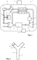
- figure 1 shows a scheme of various components of a micro gas turbine according to the invention
- figure 2 diagrammatically shows a Y shaped connection piece and a valve as may be part of a valve mechanism of the micro gas turbine.
- micro gas turbine 1 having features according to the invention, as will now be explained.
- the micro gas turbine 1 as shown and described represents only one example of many possibilities existing within the framework of the invention.
- FIG. 1 shows a scheme of various components of the micro gas turbine 1, wherein fluid flows are indicated by means of large arrows.
- the micro gas turbine 1 may be dimensioned to generate up to 30 kW electrical power, for example, although lower electric power values are possible as well.
- the micro gas turbine 1 comprises a compressor 2, a combustor 3, a turbine 4, a high speed generator 5, a recuperator 6, a heat exchanger 7 and an exhaust 8.
- the high speed generator 5 is arranged on a common shaft 9 of the compressor 2 and the turbine 4.
- air is input to the compressor 2 and fuel is input to the combustor 3.
- the compressor 2 acts to compress the air and to thereby pressurize the air, wherein the pressure of the air may be increased to about 3 bar, for example.
- the compressed air is supplied to the recuperator 6 where it is preheated under the influence of heat exchange with exhaust gas from the turbine 4.
- the compressed air is further heated under the influence of heat generated by fuel combustion in the combustor 3.
- the hot pressurized gas is expanded in the turbine 4, on the basis of which mechanical power is obtained that is used for powering both the compressor 2 and the high speed generator 5.
- the common shaft 9 performs a rotational movement as indicated by means of a small bent arrow in figure 1 .
- Exhaust gas from the turbine 4 is supplied to the recuperator 6 for heating compressed air from the compressor 2, as mentioned. After having passed the recuperator 6, the gas from the turbine 4 is made to flow through the heat exchanger 7 and finally through the exhaust 8.
- the heat exchanger 7 serves to heat a suitable medium such as water.
- output of the micro gas turbine 1 is realized at the heat exchanger 7, and also at the high speed generator 5.
- the high speed generator 5 is designed to be used to generate electric current on the basis of mechanical power
- the micro gas turbine 1 further comprises a grid converter 10 for outputting the electric current to an electric power grid (not shown).
- a controller 11 For the purpose of controlling operation of the micro gas turbine 1, a controller 11 is provided.
- the controller 11 is configured to take care that all functionalities of the micro gas turbine 1 are performed in an appropriate manner so as to realize operation of the micro gas turbine 1 as envisaged.
- the controller 11 sets a rotational speed of the rotating assembly 12 of the compressor 2, the turbine 4, the high speed generator 5 and the common shaft 9, and controls a supply of fuel to the combustor 3, to mention only two examples.
- the micro gas turbine 1 can be operated under conditions as taken into account during the designing process of the micro gas turbine 1, assuming that the design of the micro gas turbine 1 is optimized to those conditions, so that the total efficiency of the micro gas turbine 1 is optimal at those conditions.
- the temperature of the ambient air to be taken in by the compressor 2 is a variable factor. Deviation of the actual temperature of the ambient air from a reference design temperature, which may be 15°C, for example, involves a reduction of thermal efficiency of the micro gas turbine 1.
- the micro gas turbine 1 is equipped with a valve mechanism 13.
- the controller 11 When operation of the micro gas turbine 1 is initiated, the controller 11 functions to bring about an increase of the rotational speed of the rotating assembly 12. In the process, at a certain point, the maximum allowable current is reached at the grid inverter 10, at which point the increase of the rotational speed is stopped. Starting from a fully closed position of the valve mechanism 13, the at least one valve of the valve mechanism 13 is opened in a stepwise fashion, while the output current of the grid inverter 10 is checked. Every time the amount of hot gas supplied to the inlet side of the compressor 2 is increased, the mechanical power level at which the micro gas turbine 1 is operated gets reduced, as a result of which the output current is reduced as well.
- the process of gradually opening the at least one valve of the valve mechanism 13 is terminated when the rotational speed of the rotating assembly 12 is at the maximum level. From that moment on, if it is found that the level of the output current of the grid inverter 10 is lower than the highest level and even as low as the minimum level, the valve mechanism 13 is put to a further closed position, while the rotational speed of the rotating assembly 12 is kept at the maximum level. Under those circumstances, it is achieved that due to a decrease of temperature of an intake flow of the compressor 2, the mechanical power level goes up and the level of the output current of the grid inverter 10 is increased.
- micro gas turbine 1 would not comprise the valve mechanism 13 at a position between the inlet side of the compressor 2, the exhaust 8 and the cabinet 14, and if the controller 11 would not be configured so as to control the valve mechanism 13 in the way as described in the foregoing, thermal efficiency of the micro gas turbine 1 would be at a poor level when the temperature of the ambient air taken in by the compressor 2 would be relatively low, i.e. lower than the reference temperature as taken into account in the design process of the micro gas turbine 1.
- a mass flow which is large compared to mass flows used in conventional techniques such as internal combustion is needed, which causes the effect of a low ambient temperature to be significant as a large amount of thermal energy exits the micro gas turbine 1 through the exhaust 8.
- controlling the valve mechanism 13 aims at having a rotational speed of the rotating assembly 12 at a predetermined maximum level and at the same time having the output electric current of the grid converter 10 at a predetermined operative level. In the process, hot gas as available in the micro gas turbine 1 is used, wherein there is no need for an additional energy flow for achieving a controlling functionality as desired.
- the hot gas can be taken from the cabinet 14 in view of the fact that the purging mechanism 15 acts to supply air to the cabinet 14 and the fact that the temperature prevailing in the cabinet 14 is high during operation.
- the hot gas can be taken from the exhaust 8, in which case the hot gas is exhaust gas from the turbine 4 which is retrieved before exiting the micro gas turbine 1.
- valve mechanism 13 a possible embodiment of the valve mechanism 13 is illustrated.
- a Y shaped connection piece 17 and a valve 18 as may be part of the valve mechanism 13 are shown.
- the valve 18 is arranged at one of the bifurcation legs 17a, 17b of the connection piece 17, i.e. a bifurcation leg 17a which is shown at the left side in the representation as shown in figure 2 , and which will hereinafter be referred to as compressor leg 17a.
- a bifurcation leg 17b which is shown at the right side in the representation as shown in figure 2 , serves for connection of the valve mechanism 13 to the exhaust 8, and will hereinafter be referred to as exhaust leg 17b.
- the main leg 17c of the connection piece 17 serves for connecting the valve mechanism 13 to the cabinet 14, and will hereinafter be referred to as cabinet leg 17c.
- a temperature of an inlet flow of the compressor 2 is varied is dependent on a number of factors, including the functional position of the valve mechanism 13, a rotational speed of the fan 16 of the purging mechanism 15 (which may be dependent on the temperature prevailing in the cabinet 14), the rotational speed of the rotating assembly 12, and the temperature of the medium that is heated in the heat exchanger 7 as this temperature determines the temperature of the hot gas at the exhaust 8 and also, to some extent, the temperature prevailing in the cabinet 14.
- micro gas turbine 1 advantageous use can be made of the presence of a purging mechanism 15 comprising a fan 16.
- the relatively hot air from the cabinet 14 can be used in a process of keeping the thermal efficiency at an optimal level during operation of the micro gas turbine 1.
- the exhaust gas from the turbine 4 can be used in the process as mentioned, wherein advantageous use is made of the fact that the level of oxygen of the exhaust gas is still rather high even though the gas is output from an assembly including a combustor 3.
- micro gas turbine 1 When the temperature of ambient air is relatively low, thermal output and thermal efficiency of a micro gas turbine 1 decrease.
- the micro gas turbine 1 is equipped with a valve mechanism 13 by means of which the operation of the micro gas turbine 1 can be influenced and optimized, particularly by regulating a supply of hot gas as obtained during operation of the micro gas turbine 1, which may be hot gas from the cabinet 14 and/or the exhaust 8 of the micro gas turbine 1, for example, to an inlet side of the compressor 2.
- the invention also relates to a micro gas turbine 1 comprising a compressor 2 designed to take in and pressurize gas, a combustor 3 designed to take in pressurized gas from the compressor 2 and to generate hot gas on the basis of fuel combustion, a turbine 4 designed to take in and expand hot gas generated by the combustor 3, a generator 5 mechanically coupled to the turbine 4 and designed to generate electric power on the basis of mechanical power, a controller 11 designed to control operation of the micro gas turbine 1, a valve mechanism 13 which is associated with an inlet path to the compressor 2, the valve mechanism 13 being controllable by the controller 11 to open the inlet path of the compressor 2 to hot gas as obtained during operation of the micro gas turbine 1, a cabinet 14 accommodating at least the compressor 2, the combustor 3 and the turbine 4, and a purging mechanism 15 designed to realize purging of the cabinet's interior by
- air from the cabinet's interior as a default option and only additionally using exhaust air originating from the turbine 4 when such is necessary to achieve a certain supply of hot gas to the inlet side of the compressor 2 is advantageous over only using exhaust air originating from the turbine 4. In this way, heat losses through discharge of air from the cabinet's interior are kept limited. Also, air from the cabinet's interior has a higher content of oxygen and a lower content of combustion products than exhaust air originating from the turbine 4, so that it is better suited to be used in the fuel combustion process in the combustor 3.
- the invention relates to a possibility of supplying hot gas from the cabinet 14 to the inlet side of the compressor 2 without necessarily using a valve mechanism 13.
- the invention also relates to a micro gas turbine 1 comprising a compressor 2 designed to take in and pressurize gas, a combustor 3 designed to take in pressurized gas from the compressor 2 and to generate hot gas on the basis of fuel combustion, a turbine 4 designed to take in and expand hot gas generated by the combustor 3, a generator 5 mechanically coupled to the turbine 4 and designed to generate electric power on the basis of mechanical power, a cabinet 14 accommodating at least the compressor 2, the combustor 3 and the turbine 4, and a purging mechanism 15 designed to realize purging of the cabinet's interior by supplying air to the cabinet's interior, wherein an inlet path of the compressor 2 is open to the cabinet's interior for enabling the compressor 2 to take in air supplied by the purging mechanism 15 to the cabinet's interior.
Landscapes
- Engineering & Computer Science (AREA)
- Mechanical Engineering (AREA)
- General Engineering & Computer Science (AREA)
- Chemical & Material Sciences (AREA)
- Combustion & Propulsion (AREA)
- Physics & Mathematics (AREA)
- Fluid Mechanics (AREA)
- Life Sciences & Earth Sciences (AREA)
- Sustainable Development (AREA)
- Structures Of Non-Positive Displacement Pumps (AREA)
- Control Of Turbines (AREA)
- Engine Equipment That Uses Special Cycles (AREA)
- Control Of Positive-Displacement Air Blowers (AREA)
Description
- The invention relates to a micro gas turbine as defined in
claim 1 and comprising, inter alia, a compressor designed to take in and pressurize gas, a combustor designed to take in pressurized gas from the compressor and to generate hot gas on the basis of fuel combustion, a turbine designed to take in and expand hot gas generated by the combustor, a generator mechanically coupled to the turbine and designed to generate electric power on the basis of mechanical power, and a controller designed to control operation of the micro gas turbine. - The invention is in the field of gas turbines, particularly micro gas turbines. A possible application of micro gas turbines is an application for Combined Heat & Power (CHP), which does not alter the fact that other applications are feasible as well. Micro gas turbines and/or micro gas turbine based CHP systems may be used instead of conventional boilers in large houses, offices, plants, schools, stores etc., to mention one example, or may be used in hybrid electric vehicles so as to extend the range of such vehicles, to mention another example. In general, micro gas turbines are known for high reliability, low maintenance demand and low noise level, combined with high electric efficiency, low weight and low emissions.
- A micro gas turbine typically comprises a compressor, a combustor and a turbine. During operation of a micro gas turbine, ambient air is drawn in and pressurized by the compressor. The compressed air is supplied to a combustor generating hot gas on the basis of fuel combustion. It is common practice to have a special type of heat exchanger called recuperator in a micro gas turbine, which in that case serves for pre-heating the air before being supplied to the combustor. From the combustor, the hot pressurized gas is supplied to the turbine where it expands and thereby provides mechanical power for both the compressor and a generator which is mechanically coupled to the turbine.
- The mechanical power of the generator is used to generate electric power as a first type of output from the micro gas turbine. For the purpose of conveying the electric power to an electric power grid, the micro gas turbine is equipped with a suitable grid converter.
- The expanded gas, i.e. the exhaust gas from the turbine, may be made to flow through a recuperator, as mentioned, in which case heat from the exhaust gas is used for pre-heating air compressed by the compressor, prior to supplying the air to the combustor. Further, it is possible for a micro gas turbine to comprise a gas-to-liquid heat exchanger, which in that case may be used for heating water, for example, so that hot water is obtained as a second type of output from the micro gas turbine. As an alternative, ambient air from an air heating system can be heated by using an air handler, in case forced air heating is used in a building, as is often the case in North America.
- In view of practical applications of a micro gas turbine as a micro CHP system, the total efficiency of the micro gas turbine, i.e. the combination of electric efficiency and thermal efficiency, is an important characteristic of the micro gas turbine that is preferably kept as high as possible under all circumstances. In the designing process of a micro gas turbine, a certain operative output value of the electric power is taken into account. In practical situations, such operative output value may be chosen by taking into account a maximum allowable electric current value at the grid inverter, for example, or to another operative limit of one or more components of the micro gas turbine. In any case, the design of the micro gas turbine is optimized in view of the operative output value. This means that in order to realize the highest overall efficiency during actual operation of the micro gas turbine, it is advantageous to ensure that the micro gas turbine is in a mode in which the operative output value of the electric power is actually realized.
- If relatively cold ambient air is taken in by the compressor, it happens that the electric power and/or the electric efficiency of the micro gas turbine increase, while the thermal power and/or the thermal efficiency of the micro gas turbine decrease. The first effect can be understood on the basis of the general fact that compressing cold air requires less energy than compressing air of a higher temperature. Also, the operative output value of the electric power is realized at a lower rotational speed of an assembly of the compressor, the turbine and the generator, which will hereinafter be referred to as rotating assembly, as a result of which the volume of air used in the micro gas turbine is reduced and less energy is needed for heating. The second effect can be understood on the basis of the fact that a difference between the temperatures of inlet gas and outlet gas of the micro gas turbine is larger, so that the amount of thermal energy that is lost through an exhaust of the micro gas turbine is increased.
- Document
EP2876280 A1 discloses a micro gas turbine according to the preamble ofclaim 1. - It is an object of the invention to provide a way of compensating for the reducing effect on the thermal efficiency and/or the thermal power following from an intake of relatively cold ambient air. This object is achieved by means of a micro gas turbine as defined in
claim 1. - According to the invention, hot gas as obtained during operation of the micro gas turbine is used for the purpose of improving thermal efficiency and/or thermal power output of the micro gas turbine. The fact is that hot gas is available during operation of the micro gas turbine, and at least a part of the total quantity of hot gas can be used for the purpose of causing a temperature of inlet gas of the compressor to rise. Also, it is checked whether an actual value related to output electric power of the micro gas turbine, such as an actual value of the output electric current or an actual value of the electric efficiency, is below a predetermined operative value. If this appears to be the case, an increase of a rotational speed of the turbine and the generator is realized. By increasing the temperature of the gas that is taken in by the compressor, it is achieved that the electric power level and/or the electric efficiency decrease, which allows for an increase of the rotational speed of the rotating assembly until the point that the predetermined operative value related to output electric power is achieved. As long as the rotational speed of the rotating assembly is not at a predetermined maximum (which is not a mechanical maximum but a maximum in view of optimal total efficiency), the process of realizing a supply of hot gas to the compressor is carried out, wherein steps are taken in which the quantity of the hot gas that is used in the process is increased to a certain extent. Thus, as a result of every new step of the process, it is achieved that the temperature of inlet gas of the compressor is increased, wherein the predetermined operative value related to output electric power is realized at a higher rotational speed of the rotating assembly and thermal efficiency is improved as the amount of thermal energy that is output to the environment is reduced.
- The controller is further configured to repeatedly perform a subsequent process once the rotational speed of the turbine and the generator has reached the predetermined maximum value, particularly a process comprising steps of checking an actual value related to output electric power of the micro gas turbine, and, when it is found that the actual value related to the output electric power is lower than the predetermined operative value, decreasing the extent to which hot gas is allowed to flow to the compressor until the predetermined operative value related to output electric power is achieved. Thus, in the situation that operation of the micro gas turbine involves rotation of the rotating assembly at the maximum speed, maintaining the predetermined operative value related to output electric power of the micro gas turbine is done by decreasing the supply of hot gas to the compressor. As power control can no longer be realized by changing the rotational speed of the rotating assembly, the supply of hot gas to the compressor is varied for that purpose. The desired outcome of the controlling process remains the same, namely operating the micro gas turbine so that the rotational speed of the rotating assembly and the output electric power are at, or as near as possible to, values to which the design of the micro gas turbine is optimized as explained earlier. As is the case with the situation in which the rotational speed of the rotating assembly is not yet at the predetermined maximum value, the check of the actual value related to the output electric power against the predetermined operative value can be performed in successive rounds so that a stepwise decrease of the supply of hot gas to the compressor can be realized in the process of approximating the predetermined operative value related to the output electric power and thermal losses can be kept to a minimum level under the circumstances.
- It is practical if the controller is configured to perform the repeated step of checking an actual value related to output electric power at a predetermined time interval. Also, it is practical if the micro gas turbine comprises a valve mechanism which is associated with an inlet path to the compressor, the valve mechanism being controllable by the controller to open the inlet path of the compressor to hot gas as obtained during operation of the micro gas turbine.
- As mentioned in the foregoing, hot gas is available during operation of the micro gas turbine. According to a first feasible option, hot gas can be retrieved from a cabinet of the micro gas turbine in which the compressor, the combustor, the turbine and more components of the micro gas turbine are accommodated, assuming that the micro gas turbine further comprises a purging mechanism designed to realize purging of the cabinet's interior by supplying air to the cabinet's interior. In that case, it is practical for the valve mechanism to be controllable by the controller to open the inlet path of the compressor to the cabinet's interior for enabling the compressor to take in air supplied by the purging mechanism to the cabinet's interior. The fact is that the cabinet's interior is hot during operation of the micro gas turbine due to operation of the combustor and other components of the micro gas turbine. According to the invention, hot gas can be retrieved at a position that is at an outlet side of the turbine, in which case the valve mechanism may be designed so as to be controllable by the controller to open the inlet path of the compressor to an exhaust associated with the turbine for enabling the compressor to take in exhaust gas from the turbine. In the practical case that one or more heat exchangers such as a recuperator and a gas-to-liquid heat exchanger are arranged at the outlet side of the turbine, such an exhaust is positioned downstream of the one or more heat exchangers.
- In respect of this feasible option, it is noted that the air excess ratio of a micro gas turbine having a recuperator is significantly larger than the air excess ratio of conventional internal combustion engines. A typical value of the air to fuel mass ratio of a micro gas turbine, i.e. the mass ratio of air to fuel present in the combustion process taking place in the micro gas turbine during operation thereof, is 90:1. On the one hand, a high mass flow rate of air involves higher heat losses compared to a system working at near stoichiometric combustion conditions. On the other hand, the high mass flow rate of air allows for using the exhaust gas from the turbine as inlet gas of the compressor, as the exhaust gas from the turbine still contains a rather high amount of oxygen.
- Within the framework of the invention, the micro gas turbine may be designed so as to allow for use of hot gas originating from either one or both of the cabinet and the outlet side of the turbine. In the latter case, it is practical for the valve mechanism to comprise a valve and a connection piece having three connection areas, the compressor being connected to one of the connection areas of the connection piece through the valve, the exhaust being connected to another of the connection areas of the connection piece, and the cabinet being connected to yet another of the connection areas of the connection piece. For example, the connection piece may be Y shaped and comprise two bifurcation legs and one main leg, the compressor being connected to one of the bifurcation legs of the connection piece through the valve, the exhaust associated with the turbine being connected to the other of the bifurcation legs of the connection piece, and the cabinet being connected to the main leg of the connection piece. In such a case, there is no need for applying complex valve constructions and associated complex control features. Due to operation of the compressor, it is automatically achieved that a slight underpressure prevails at the one of the bifurcation legs of the connection piece. Further, assuming that the purging mechanism comprises a ventilating mechanism designed to generate a flow of air in the cabinet, it is automatically achieved that a higher pressure prevails at the other of the bifurcation legs of the connection piece. As a result, when the valve is opened, a flow of hot air from the cabinet to the compressor is enabled. By opening the valve further and further, it is eventually achieved that a flow of hot gas originating from the turbine is sucked in as well. In this configuration, if the valve is closed, the normal situation of the air from the cabinet being discharged along with the exhaust gas from the turbine is realized.
- An Y shaped connection piece is just one example of a component that may be applied in a practical embodiment of the valve mechanism. Alternatively, a T shaped connection piece or another connection piece having three legs/branches may be used, for example.
- As mentioned earlier, in practical cases, the micro gas turbine further comprises a grid converter designed to output electric power generated by the micro gas turbine during operation thereof to an electric power grid. According to one possibility, the predetermined operative value related to the output electric power of the micro gas turbine may be chosen in relation to a maximum allowable current level at the grid converter, i.e. may be linked to the maximum allowable current level at the grid converter.
- It follows from the foregoing that the invention provides an algorithm for controlling the micro gas turbine so as to achieve that thermal efficiency of the micro gas turbine during operation thereof is kept optimal under various circumstances. In particular, the invention provides measures for improving thermal efficiency in case the ambient air that is to be supplied to the compressor is relatively cold. A practical example of a value of the temperature that is taken as an assumption during the designing process of the micro gas turbine is 15°C. Practical examples of maximum/optimal values of the rotational speed of the rotating assembly and an output electric current of the grid converter are 240,000 rpm and 14 A, respectively, wherein it is noted that these values may be associated with a micro gas turbine for generating about 3 kW electrical power.
- The micro gas turbine according to the invention may be of any practical type. In that respect, it is noted that the micro gas turbine may comprise a heat exchanger being configured and arranged to serve as a recuperator for pre-heating pressurized gas obtained from the compressor before being supplied to the combustor by allowing the pressurized gas to exchange heat with exhaust gas from the turbine, as is common in the field of micro gas turbines. Likewise, the micro gas turbine may comprise a heat exchanger being configured and arranged to serve for heating an external medium by allowing the external medium to exchange heat with exhaust gas from the turbine.
- The invention will be further elucidated on the basis of the following description of an example of a micro gas turbine which is designed to be operated at optimal thermal efficiency, even when the air that is to be taken in by the compressor of the micro gas turbine is relatively cold, i.e. at a temperature which is lower than a reference design temperature. Reference will be made to the drawing, in which:
figure 1 shows a scheme of various components of a micro gas turbine according to the invention; andfigure 2 diagrammatically shows a Y shaped connection piece and a valve as may be part of a valve mechanism of the micro gas turbine. - The figures relate to a
micro gas turbine 1 having features according to the invention, as will now be explained. Themicro gas turbine 1 as shown and described represents only one example of many possibilities existing within the framework of the invention. -
Figure 1 shows a scheme of various components of themicro gas turbine 1, wherein fluid flows are indicated by means of large arrows. Themicro gas turbine 1 may be dimensioned to generate up to 30 kW electrical power, for example, although lower electric power values are possible as well. Themicro gas turbine 1 comprises acompressor 2, acombustor 3, a turbine 4, ahigh speed generator 5, arecuperator 6, a heat exchanger 7 and anexhaust 8. Thehigh speed generator 5 is arranged on acommon shaft 9 of thecompressor 2 and the turbine 4. When themicro gas turbine 1 is operated, air is input to thecompressor 2 and fuel is input to thecombustor 3. Thecompressor 2 acts to compress the air and to thereby pressurize the air, wherein the pressure of the air may be increased to about 3 bar, for example. The compressed air is supplied to therecuperator 6 where it is preheated under the influence of heat exchange with exhaust gas from the turbine 4. The compressed air is further heated under the influence of heat generated by fuel combustion in thecombustor 3. The hot pressurized gas is expanded in the turbine 4, on the basis of which mechanical power is obtained that is used for powering both thecompressor 2 and thehigh speed generator 5. In the process, thecommon shaft 9 performs a rotational movement as indicated by means of a small bent arrow infigure 1 . - Exhaust gas from the turbine 4 is supplied to the
recuperator 6 for heating compressed air from thecompressor 2, as mentioned. After having passed therecuperator 6, the gas from the turbine 4 is made to flow through the heat exchanger 7 and finally through theexhaust 8. The heat exchanger 7 serves to heat a suitable medium such as water. Thus, output of themicro gas turbine 1 is realized at the heat exchanger 7, and also at thehigh speed generator 5. In respect of the latter, it is noted that thehigh speed generator 5 is designed to be used to generate electric current on the basis of mechanical power, and that themicro gas turbine 1 further comprises agrid converter 10 for outputting the electric current to an electric power grid (not shown). - For the purpose of controlling operation of the
micro gas turbine 1, acontroller 11 is provided. Thecontroller 11 is configured to take care that all functionalities of themicro gas turbine 1 are performed in an appropriate manner so as to realize operation of themicro gas turbine 1 as envisaged. Thecontroller 11 sets a rotational speed of the rotatingassembly 12 of thecompressor 2, the turbine 4, thehigh speed generator 5 and thecommon shaft 9, and controls a supply of fuel to thecombustor 3, to mention only two examples. - It is advantageous if the
micro gas turbine 1 can be operated under conditions as taken into account during the designing process of themicro gas turbine 1, assuming that the design of themicro gas turbine 1 is optimized to those conditions, so that the total efficiency of themicro gas turbine 1 is optimal at those conditions. However, the practical fact is that out of those conditions, the temperature of the ambient air to be taken in by thecompressor 2 is a variable factor. Deviation of the actual temperature of the ambient air from a reference design temperature, which may be 15°C, for example, involves a reduction of thermal efficiency of themicro gas turbine 1. In order to compensate for this phenomenon, at least as much as possible in case the actual temperature of the ambient air is lower than the reference design temperature, themicro gas turbine 1 is equipped with avalve mechanism 13. - In the shown example, the
valve mechanism 13 is associated with an inlet side of thecompressor 2, with theexhaust 8, and with acabinet 14 in which various components of themicro gas turbine 1, including thecompressor 2, thecombustor 3 and the turbine 4, are accommodated. Thevalve mechanism 13 comprises at least one valve at a position between the inlet side of thecompressor 2 on the one hand and theexhaust 8 and thecabinet 14 on the other hand. Also, themicro gas turbine 1 comprises apurging mechanism 15 including afan 16 for supplying purging air to thecabinet 14 and generating a flow of the purging air inside thecabinet 14. This is done to minimize a risk of accumulation of inflammable/explosive gases in thecabinet 14 which may take place in case unexpected leaks occur, for example. - When operation of the
micro gas turbine 1 is initiated, thecontroller 11 functions to bring about an increase of the rotational speed of the rotatingassembly 12. In the process, at a certain point, the maximum allowable current is reached at thegrid inverter 10, at which point the increase of the rotational speed is stopped. Starting from a fully closed position of thevalve mechanism 13, the at least one valve of thevalve mechanism 13 is opened in a stepwise fashion, while the output current of thegrid inverter 10 is checked. Every time the amount of hot gas supplied to the inlet side of thecompressor 2 is increased, the mechanical power level at which themicro gas turbine 1 is operated gets reduced, as a result of which the output current is reduced as well. As soon as the output current reaches a certain minimum allowable value, a process in which the rotational speed of the rotatingassembly 12 is increased takes place, after which the supply of hot gas to the inlet side of thecompressor 2 is increased and the process which leads to increase of rotational speed of the rotatingassembly 12 is started all over again. Hence, by gradually increasing the supply of hot gas to the inlet side of thecompressor 2, it is achieved that the rotational speed can be made to approximate the design rotational speed. For the purpose of checking the level of the output current at thegrid converter 10, any suitable means may be applied. - The process of gradually opening the at least one valve of the
valve mechanism 13 is terminated when the rotational speed of the rotatingassembly 12 is at the maximum level. From that moment on, if it is found that the level of the output current of thegrid inverter 10 is lower than the highest level and even as low as the minimum level, thevalve mechanism 13 is put to a further closed position, while the rotational speed of the rotatingassembly 12 is kept at the maximum level. Under those circumstances, it is achieved that due to a decrease of temperature of an intake flow of thecompressor 2, the mechanical power level goes up and the level of the output current of thegrid inverter 10 is increased. - If the
micro gas turbine 1 would not comprise thevalve mechanism 13 at a position between the inlet side of thecompressor 2, theexhaust 8 and thecabinet 14, and if thecontroller 11 would not be configured so as to control thevalve mechanism 13 in the way as described in the foregoing, thermal efficiency of themicro gas turbine 1 would be at a poor level when the temperature of the ambient air taken in by thecompressor 2 would be relatively low, i.e. lower than the reference temperature as taken into account in the design process of themicro gas turbine 1. In order to ensure proper operation of themicro gas turbine 1, a mass flow which is large compared to mass flows used in conventional techniques such as internal combustion is needed, which causes the effect of a low ambient temperature to be significant as a large amount of thermal energy exits themicro gas turbine 1 through theexhaust 8. - By having the
valve mechanism 13 and controlling thevalve mechanism 13 in a specific manner, it is achieved that the actual operational conditions of themicro gas turbine 1 can be made to approximate the reference design conditions, wherein the thermal efficiency of themicro gas turbine 1 can be kept as high as possible. In particular, controlling thevalve mechanism 13 aims at having a rotational speed of the rotatingassembly 12 at a predetermined maximum level and at the same time having the output electric current of thegrid converter 10 at a predetermined operative level. In the process, hot gas as available in themicro gas turbine 1 is used, wherein there is no need for an additional energy flow for achieving a controlling functionality as desired. The hot gas can be taken from thecabinet 14 in view of the fact that thepurging mechanism 15 acts to supply air to thecabinet 14 and the fact that the temperature prevailing in thecabinet 14 is high during operation. Alternatively or in addition, the hot gas can be taken from theexhaust 8, in which case the hot gas is exhaust gas from the turbine 4 which is retrieved before exiting themicro gas turbine 1. - In
figure 2 , a possible embodiment of thevalve mechanism 13 is illustrated. In particular, a Y shapedconnection piece 17 and avalve 18 as may be part of thevalve mechanism 13 are shown. Thevalve 18 is arranged at one of thebifurcation legs connection piece 17, i.e. abifurcation leg 17a which is shown at the left side in the representation as shown infigure 2 , and which will hereinafter be referred to ascompressor leg 17a. The other of thebifurcation legs connection piece 17, i.e. abifurcation leg 17b which is shown at the right side in the representation as shown infigure 2 , serves for connection of thevalve mechanism 13 to theexhaust 8, and will hereinafter be referred to asexhaust leg 17b. Themain leg 17c of theconnection piece 17 serves for connecting thevalve mechanism 13 to thecabinet 14, and will hereinafter be referred to ascabinet leg 17c. - On the basis of the flow which is created by the
compressor 2 during operation of themicro gas turbine 1, a slight underpressure is prevailing at an inlet side of thevalve 18, i.e. in thecompressor leg 17a. Under the influence of operation of thefan 16 of thepurging mechanism 15, the pressure prevailing in thecabinet leg 17c is at a higher level, so that an air flow from thecabinet 14 to thecompressor 2 is obtained when thevalve 18 is opened. When thevalve 18 is fully opened, a flow of gas from theexhaust 8 is realized as well, wherein the gas is drawn in through theexhaust leg 17b. If thevalve 18 is fully closed or almost fully closed, an air flow from thecabinet 14 to theexhaust 8 will be obtained. - It is noted that the extent to which a temperature of an inlet flow of the
compressor 2 is varied is dependent on a number of factors, including the functional position of thevalve mechanism 13, a rotational speed of thefan 16 of the purging mechanism 15 (which may be dependent on the temperature prevailing in the cabinet 14), the rotational speed of the rotatingassembly 12, and the temperature of the medium that is heated in the heat exchanger 7 as this temperature determines the temperature of the hot gas at theexhaust 8 and also, to some extent, the temperature prevailing in thecabinet 14. - It follows from the foregoing that in the
micro gas turbine 1 according to the invention, advantageous use can be made of the presence of apurging mechanism 15 comprising afan 16. The relatively hot air from thecabinet 14 can be used in a process of keeping the thermal efficiency at an optimal level during operation of themicro gas turbine 1. Also, the exhaust gas from the turbine 4 can be used in the process as mentioned, wherein advantageous use is made of the fact that the level of oxygen of the exhaust gas is still rather high even though the gas is output from an assembly including acombustor 3. - It will be clear to a person skilled in the art that the scope of the invention is not limited to the examples discussed in the foregoing, but that several amendments and modifications thereof are possible without deviating from the scope of the invention as defined in the attached claims.
- For the sake of completeness, it is noted that where aspects of the invention like "the rotational speed of the rotating
assembly 12 is at the maximum level" are mentioned, these are to be understood for their practical meaning, taking into account that in fact a tolerance window is applicable. - A possible summary of the invention reads follows. When the temperature of ambient air is relatively low, thermal output and thermal efficiency of a
micro gas turbine 1 decrease. In order to compensate for the loss of thermal efficiency, themicro gas turbine 1 is equipped with avalve mechanism 13 by means of which the operation of themicro gas turbine 1 can be influenced and optimized, particularly by regulating a supply of hot gas as obtained during operation of themicro gas turbine 1, which may be hot gas from thecabinet 14 and/or theexhaust 8 of themicro gas turbine 1, for example, to an inlet side of thecompressor 2. - The concept of having a possibility of supplying hot gas from the
cabinet 14 to the inlet side of thecompressor 2 is not necessarily linked to a particular way of controlling operation of themicro gas turbine 1. In view thereof, the invention also relates to amicro gas turbine 1 comprising acompressor 2 designed to take in and pressurize gas, acombustor 3 designed to take in pressurized gas from thecompressor 2 and to generate hot gas on the basis of fuel combustion, a turbine 4 designed to take in and expand hot gas generated by thecombustor 3, agenerator 5 mechanically coupled to the turbine 4 and designed to generate electric power on the basis of mechanical power, acontroller 11 designed to control operation of themicro gas turbine 1, avalve mechanism 13 which is associated with an inlet path to thecompressor 2, thevalve mechanism 13 being controllable by thecontroller 11 to open the inlet path of thecompressor 2 to hot gas as obtained during operation of themicro gas turbine 1, acabinet 14 accommodating at least thecompressor 2, thecombustor 3 and the turbine 4, and apurging mechanism 15 designed to realize purging of the cabinet's interior by supplying air to the cabinet's interior, wherein thevalve mechanism 13 is controllable by thecontroller 11 to open the inlet path of thecompressor 2 to the cabinet's interior for enabling thecompressor 2 to take in air supplied by thepurging mechanism 15 to the cabinet's interior. - Using air from the cabinet's interior as a default option and only additionally using exhaust air originating from the turbine 4 when such is necessary to achieve a certain supply of hot gas to the inlet side of the
compressor 2 is advantageous over only using exhaust air originating from the turbine 4. In this way, heat losses through discharge of air from the cabinet's interior are kept limited. Also, air from the cabinet's interior has a higher content of oxygen and a lower content of combustion products than exhaust air originating from the turbine 4, so that it is better suited to be used in the fuel combustion process in thecombustor 3. - Further, the invention relates to a possibility of supplying hot gas from the
cabinet 14 to the inlet side of thecompressor 2 without necessarily using avalve mechanism 13. In view thereof, the invention also relates to amicro gas turbine 1 comprising acompressor 2 designed to take in and pressurize gas, acombustor 3 designed to take in pressurized gas from thecompressor 2 and to generate hot gas on the basis of fuel combustion, a turbine 4 designed to take in and expand hot gas generated by thecombustor 3, agenerator 5 mechanically coupled to the turbine 4 and designed to generate electric power on the basis of mechanical power, acabinet 14 accommodating at least thecompressor 2, thecombustor 3 and the turbine 4, and apurging mechanism 15 designed to realize purging of the cabinet's interior by supplying air to the cabinet's interior, wherein an inlet path of thecompressor 2 is open to the cabinet's interior for enabling thecompressor 2 to take in air supplied by thepurging mechanism 15 to the cabinet's interior.
Claims (11)
- Micro gas turbine (1) comprising- a compressor (2) designed to take in and pressurize gas,- a combustor (3) designed to take in pressurized gas from the compressor (2) and to generate hot gas on the basis of fuel combustion,- a turbine (4) designed to take in and expand hot gas generated by the combustor (3),- a generator (5) mechanically coupled to the turbine (4) and designed to generate electric power on the basis of mechanical power,- a controller (11) designed to control operation of the micro gas turbine (1),- a valve mechanism (13) which is associated with an inlet path to the compressor (2), the micro gas turbine (1) being characterized by further comprising :- a cabinet (14) accommodating at least the compressor (2), the combustor (3) and the turbine (4), and- a purging mechanism (15) designed to realize purging of the cabinet's interior by supplying air to the cabinet's interior, wherein the valve mechanism (13) is controllable by the controller (11) to open the inlet path of the compressor (2) to the cabinet's interior for enabling the compressor (2) to take in air from the cabinet's interior, and wherein the valve mechanism (13) is also controllable by the controller (11) to open the inlet path of the compressor (2) to an exhaust (8) associated with the turbine (4) for enabling the compressor (2) to take in exhaust gas from the turbine (4).
- Micro gas turbine (1) according to claim 1, wherein the valve mechanism (13) comprises a valve (18) and a connection piece (17) having three connection areas, the compressor (2) being connected to one of the connection areas of the connection piece (17) through the valve (18), the exhaust (8) being connected to another of the connection areas of the connection piece, and the cabinet (14) being connected to yet another of the connection areas of the connection piece (17).
- Micro gas turbine (1) according to claim 2, wherein the connection piece (17) is Y shaped and comprises two bifurcation legs (17a, 17b) and a main leg (17c), the compressor (2) being connected to one of the bifurcation legs (17a, 17b) of the connection piece (17) through the valve (18), the exhaust (8) being connected to the other of the bifurcation legs (17a, 17b) of the connection piece (17), and the cabinet (14) being connected to the main leg (17c) of the connection piece (17).
- Micro gas turbine (1) according to any of claims 1-3, wherein the purging mechanism (15) comprises a ventilating mechanism (16) designed to generate a flow of air in the cabinet (14).
- Micro gas turbine (1) according to any of claims 1-4, wherein the controller (11) is configured to repeatedly perform a process comprising steps of controlling the valve mechanism (13) to allow air from the cabinet (14) and/or exhaust gas from the exhaust (8) to flow to the compressor (2), besides ambient air, checking an actual value related to output electric power of the micro gas turbine (1), and, when it is found that the actual value related to the output electric power is lower than a predetermined operative value, driving the micro gas turbine (1) for increasing a rotational speed of the turbine (4) and the generator (5) until the predetermined operative value related to output electric power is achieved, to increase a supply of the air from the cabinet (14) and/or the exhaust gas from the exhaust (8) to the inlet path of the compressor (2) each time the process is repeated, and to perform the process as long as the rotational speed of the turbine (4) and the generator (5) is below a predetermined maximum value.
- Micro gas turbine (1) according to claim 5, wherein the controller (11) is further configured to repeatedly perform a subsequent process once the rotational speed of the turbine (4) and the generator (5) has reached the predetermined maximum value, particularly a process comprising steps of checking an actual value related to output electric power of the micro gas turbine (1), and, when it is found that the actual value related to the output electric power is lower than the predetermined operative value, controlling the valve mechanism (13) to decrease the supply of the air from the cabinet (14) and/or the exhaust gas from the exhaust (8) to the inlet path of the compressor (2) until the predetermined operative value related to output electric power is achieved.
- Micro gas turbine (1) according to claim 5 or 6, wherein the controller (11) is configured to perform the repeated step of checking an actual value related to output electric power at a predetermined time interval.
- Micro gas turbine (1) according to any of claims 5-7, wherein the value related to the output electric power of the micro gas turbine (1) is one of a value of output electric current of the micro gas turbine (1) and a value of electric efficiency of the micro gas turbine (1).
- Micro gas turbine (1) according to any of claims 1-8, comprising a grid converter (10) designed to output electric power generated by the micro gas turbine (1) during operation thereof to an electric power grid.
- Micro gas turbine (1) according to any of claims 1-9, comprising a heat exchanger (6) being configured and arranged to serve as a recuperator for pre-heating pressurized gas obtained from the compressor (2) before being supplied to the combustor (3) by allowing the pressurized gas to exchange heat with exhaust gas from the exhaust (8).
- Micro gas turbine (1) according to any of claims 1-10, comprising a heat exchanger (7) being configured and arranged to serve for heating an external medium by allowing the external medium to exchange heat with exhaust gas from the exhaust (8).
Applications Claiming Priority (2)
| Application Number | Priority Date | Filing Date | Title |
|---|---|---|---|
| NL2019940A NL2019940B1 (en) | 2017-11-20 | 2017-11-20 | Micro gas turbine designed to limit heat losses therefrom |
| PCT/NL2018/050771 WO2019098836A1 (en) | 2017-11-20 | 2018-11-19 | Micro gas turbine designed to limit heat losses therefrom |
Publications (2)
| Publication Number | Publication Date |
|---|---|
| EP3714147A1 EP3714147A1 (en) | 2020-09-30 |
| EP3714147B1 true EP3714147B1 (en) | 2024-08-28 |
Family
ID=61003323
Family Applications (1)
| Application Number | Title | Priority Date | Filing Date |
|---|---|---|---|
| EP18840082.4A Active EP3714147B1 (en) | 2017-11-20 | 2018-11-19 | Micro gas turbine designed to limit heat losses therefrom |
Country Status (6)
| Country | Link |
|---|---|
| US (2) | US20200340398A1 (en) |
| EP (1) | EP3714147B1 (en) |
| JP (1) | JP7219765B2 (en) |
| CN (1) | CN111373132B (en) |
| NL (1) | NL2019940B1 (en) |
| WO (1) | WO2019098836A1 (en) |
Families Citing this family (1)
| Publication number | Priority date | Publication date | Assignee | Title |
|---|---|---|---|---|
| US11824424B2 (en) | 2021-09-10 | 2023-11-21 | Hamilton Sundstrand Corporation | Combined integrated waste heat recovery and inlet pressure boost system |
Family Cites Families (23)
| Publication number | Priority date | Publication date | Assignee | Title |
|---|---|---|---|---|
| JP2814863B2 (en) * | 1992-12-07 | 1998-10-27 | 日産自動車株式会社 | Generator control device |
| JP2003020912A (en) | 2001-07-06 | 2003-01-24 | Mitsubishi Heavy Ind Ltd | Micro gas turbine cogeneration system |
| US6777822B1 (en) * | 2003-04-01 | 2004-08-17 | Hamilton Sundstrand Corporation | Control system for an auxiliary power unit |
| JP2005090367A (en) | 2003-09-18 | 2005-04-07 | Meidensha Corp | Micro gas turbine power generation system |
| US20080048456A1 (en) * | 2006-08-23 | 2008-02-28 | Northern Power Systems, Inc. | Modular microturbine system |
| AT505686B1 (en) * | 2007-08-27 | 2011-05-15 | Vaillant Group Austria Gmbh | POWER-HEATER COUPLING SYSTEM AND METHOD FOR THE POWER CONTROL OF SUCH AN APPARATUS |
| EP2433080A4 (en) * | 2009-05-22 | 2014-12-10 | Us Gov Sec Navy | RADIAL COMPACT BACKWATER RECOVERY |
| US9297316B2 (en) * | 2011-11-23 | 2016-03-29 | General Electric Company | Method and apparatus for optimizing the operation of a turbine system under flexible loads |
| EP2679786A1 (en) * | 2012-06-28 | 2014-01-01 | Alstom Technology Ltd | Stand-by operation of a gas turbine |
| JP2014118927A (en) | 2012-12-19 | 2014-06-30 | Hitachi Ltd | Gas turbine generator set |
| US10208677B2 (en) | 2012-12-31 | 2019-02-19 | General Electric Company | Gas turbine load control system |
| DE102014206474A1 (en) * | 2013-04-05 | 2014-10-09 | Dürr Systems GmbH | Plant for providing heat energy for heat consumers |
| DE102013112892A1 (en) * | 2013-11-21 | 2015-05-21 | Deutsches Zentrum für Luft- und Raumfahrt e.V. | Micro gas turbine arrangement |
| GB201322062D0 (en) * | 2013-12-13 | 2014-01-29 | Optimized Systems And Solutions Ltd | System abnormalities |
| US10079564B2 (en) | 2014-01-27 | 2018-09-18 | General Electric Company | System and method for a stoichiometric exhaust gas recirculation gas turbine system |
| US9915167B2 (en) * | 2015-11-20 | 2018-03-13 | Ansaldo Energia Switzerland AG | Detection of deficient sensors in a gas turbine system |
| JP6913108B2 (en) * | 2016-04-20 | 2021-08-04 | ゼネラル・エレクトリック・カンパニイ | Active noise canceling system and equipment |
| US20170306846A1 (en) * | 2016-04-22 | 2017-10-26 | General Electric Company | Ventilation system for turbomachine using bladeless airflow amplifier |
| US20170306845A1 (en) * | 2016-04-22 | 2017-10-26 | General Electric Company | Ventilation system for turbomachine using bladeless airflow amplifier |
| US20170342900A1 (en) * | 2016-05-27 | 2017-11-30 | General Electric Company | System and method of compressor inlet temperature control with eductor |
| US20180291820A1 (en) * | 2017-04-05 | 2018-10-11 | General Electric Company | Malfunction determination for gas turbine enclosure |
| CA3001566A1 (en) * | 2017-04-13 | 2018-10-13 | Pratt & Whitney Canada Corp. | System and method for variable geometry mechanism control |
| US11578621B2 (en) * | 2020-04-08 | 2023-02-14 | General Electric Company | System for cooling turbine shaft coupling |
-
2017
- 2017-11-20 NL NL2019940A patent/NL2019940B1/en active
-
2018
- 2018-11-19 CN CN201880075039.6A patent/CN111373132B/en active Active
- 2018-11-19 EP EP18840082.4A patent/EP3714147B1/en active Active
- 2018-11-19 US US16/764,872 patent/US20200340398A1/en not_active Abandoned
- 2018-11-19 JP JP2020527926A patent/JP7219765B2/en active Active
- 2018-11-19 WO PCT/NL2018/050771 patent/WO2019098836A1/en not_active Ceased
-
2024
- 2024-05-16 US US18/665,680 patent/US20240301820A1/en active Pending
Also Published As
| Publication number | Publication date |
|---|---|
| US20200340398A1 (en) | 2020-10-29 |
| EP3714147A1 (en) | 2020-09-30 |
| CN111373132A (en) | 2020-07-03 |
| JP7219765B2 (en) | 2023-02-08 |
| JP2021503578A (en) | 2021-02-12 |
| NL2019940B1 (en) | 2019-05-24 |
| CN111373132B (en) | 2023-06-09 |
| US20240301820A1 (en) | 2024-09-12 |
| WO2019098836A1 (en) | 2019-05-23 |
Similar Documents
| Publication | Publication Date | Title |
|---|---|---|
| CN104995376B (en) | Combustion gas turbine and operational approach in Mechanical Driven application | |
| CN103452667B (en) | Method for pressure charging system, combustion gas turbine systems and the operating gas turbine of combustion gas turbine systems | |
| EP1898066B1 (en) | High humidity gas turbine system with humidifier bypass | |
| US11187150B2 (en) | Combined cycle heat engine comprising a first and second gas turbine engine | |
| US7293414B1 (en) | High performance method for throttling of closed gas turbine cycles | |
| US20240301820A1 (en) | Micro gas turbine designed to limit heat losses therefrom | |
| EP2623751B1 (en) | Method and apparatus to control part-load performance of a turbine | |
| JPH0763010A (en) | Starting method of single-axis combined cycle power generation facility | |
| CN106907241A (en) | The system and method for supplying control exhaust energy by exhaust damper and compressed gas | |
| JPH04234534A (en) | Gas turbine device and method for driving same | |
| WO2002090721A1 (en) | Power generation apparatus | |
| JP7472035B2 (en) | Cogeneration system for boilers | |
| EP4168712A1 (en) | Burner with gas turbine for producing a flame for a heat generation system | |
| JP7012863B2 (en) | How to start a gas turbine engine for a combined cycle power generator | |
| JP5023107B2 (en) | Regenerative cycle gas turbine system | |
| EP3841288B1 (en) | Fuel/air supply device | |
| KR102058356B1 (en) | Combined cycle power generation system | |
| JP6382755B2 (en) | Fuel cell combined power generation system and operation method thereof | |
| RU2767677C1 (en) | Method of reducing the power of a gas turbine plant below its permissible lower limit of the control range | |
| JPH07166814A (en) | How to start a uniaxial combined cycle power plant | |
| US20260022659A1 (en) | Intake air heating system, operation method for intake air heating system, and gas turbine system | |
| RU43918U1 (en) | GAS-TURBINE BOX USING GAS GENERATOR ENERGY | |
| JP6625848B2 (en) | Steam control valve control device, power plant and steam control valve control method | |
| JPH0341644B2 (en) | ||
| Bammert et al. | Part-load behavior of a solar-heated and fossil-fueled gas turbine power plant |
Legal Events
| Date | Code | Title | Description |
|---|---|---|---|
| STAA | Information on the status of an ep patent application or granted ep patent |
Free format text: STATUS: UNKNOWN |
|
| STAA | Information on the status of an ep patent application or granted ep patent |
Free format text: STATUS: THE INTERNATIONAL PUBLICATION HAS BEEN MADE |
|
| PUAI | Public reference made under article 153(3) epc to a published international application that has entered the european phase |
Free format text: ORIGINAL CODE: 0009012 |
|
| STAA | Information on the status of an ep patent application or granted ep patent |
Free format text: STATUS: REQUEST FOR EXAMINATION WAS MADE |
|
| 17P | Request for examination filed |
Effective date: 20200619 |
|
| AK | Designated contracting states |
Kind code of ref document: A1 Designated state(s): AL AT BE BG CH CY CZ DE DK EE ES FI FR GB GR HR HU IE IS IT LI LT LU LV MC MK MT NL NO PL PT RO RS SE SI SK SM TR |
|
| AX | Request for extension of the european patent |
Extension state: BA ME |
|
| DAV | Request for validation of the european patent (deleted) | ||
| DAX | Request for extension of the european patent (deleted) | ||
| STAA | Information on the status of an ep patent application or granted ep patent |
Free format text: STATUS: EXAMINATION IS IN PROGRESS |
|
| 17Q | First examination report despatched |
Effective date: 20220608 |
|
| P01 | Opt-out of the competence of the unified patent court (upc) registered |
Effective date: 20230510 |
|
| GRAP | Despatch of communication of intention to grant a patent |
Free format text: ORIGINAL CODE: EPIDOSNIGR1 |
|
| STAA | Information on the status of an ep patent application or granted ep patent |
Free format text: STATUS: GRANT OF PATENT IS INTENDED |
|
| INTG | Intention to grant announced |
Effective date: 20240320 |
|
| GRAS | Grant fee paid |
Free format text: ORIGINAL CODE: EPIDOSNIGR3 |
|
| GRAA | (expected) grant |
Free format text: ORIGINAL CODE: 0009210 |
|
| STAA | Information on the status of an ep patent application or granted ep patent |
Free format text: STATUS: THE PATENT HAS BEEN GRANTED |
|
| AK | Designated contracting states |
Kind code of ref document: B1 Designated state(s): AL AT BE BG CH CY CZ DE DK EE ES FI FR GB GR HR HU IE IS IT LI LT LU LV MC MK MT NL NO PL PT RO RS SE SI SK SM TR |
|
| REG | Reference to a national code |
Ref country code: GB Ref legal event code: FG4D |
|
| REG | Reference to a national code |
Ref country code: CH Ref legal event code: EP |
|
| REG | Reference to a national code |
Ref country code: DE Ref legal event code: R096 Ref document number: 602018073738 Country of ref document: DE |
|
| REG | Reference to a national code |
Ref country code: IE Ref legal event code: FG4D |
|
| REG | Reference to a national code |
Ref country code: NL Ref legal event code: FP |
|
| REG | Reference to a national code |
Ref country code: LT Ref legal event code: MG9D |
|
| PG25 | Lapsed in a contracting state [announced via postgrant information from national office to epo] |
Ref country code: NO Free format text: LAPSE BECAUSE OF FAILURE TO SUBMIT A TRANSLATION OF THE DESCRIPTION OR TO PAY THE FEE WITHIN THE PRESCRIBED TIME-LIMIT Effective date: 20241128 |
|
| REG | Reference to a national code |
Ref country code: AT Ref legal event code: MK05 Ref document number: 1718158 Country of ref document: AT Kind code of ref document: T Effective date: 20240828 |
|
| PG25 | Lapsed in a contracting state [announced via postgrant information from national office to epo] |
Ref country code: PT Free format text: LAPSE BECAUSE OF FAILURE TO SUBMIT A TRANSLATION OF THE DESCRIPTION OR TO PAY THE FEE WITHIN THE PRESCRIBED TIME-LIMIT Effective date: 20241230 Ref country code: GR Free format text: LAPSE BECAUSE OF FAILURE TO SUBMIT A TRANSLATION OF THE DESCRIPTION OR TO PAY THE FEE WITHIN THE PRESCRIBED TIME-LIMIT Effective date: 20241129 Ref country code: FI Free format text: LAPSE BECAUSE OF FAILURE TO SUBMIT A TRANSLATION OF THE DESCRIPTION OR TO PAY THE FEE WITHIN THE PRESCRIBED TIME-LIMIT Effective date: 20240828 Ref country code: PL Free format text: LAPSE BECAUSE OF FAILURE TO SUBMIT A TRANSLATION OF THE DESCRIPTION OR TO PAY THE FEE WITHIN THE PRESCRIBED TIME-LIMIT Effective date: 20240828 |
|
| PG25 | Lapsed in a contracting state [announced via postgrant information from national office to epo] |
Ref country code: BG Free format text: LAPSE BECAUSE OF FAILURE TO SUBMIT A TRANSLATION OF THE DESCRIPTION OR TO PAY THE FEE WITHIN THE PRESCRIBED TIME-LIMIT Effective date: 20240828 |
|
| PG25 | Lapsed in a contracting state [announced via postgrant information from national office to epo] |
Ref country code: LV Free format text: LAPSE BECAUSE OF FAILURE TO SUBMIT A TRANSLATION OF THE DESCRIPTION OR TO PAY THE FEE WITHIN THE PRESCRIBED TIME-LIMIT Effective date: 20240828 |
|
| PG25 | Lapsed in a contracting state [announced via postgrant information from national office to epo] |
Ref country code: IS Free format text: LAPSE BECAUSE OF FAILURE TO SUBMIT A TRANSLATION OF THE DESCRIPTION OR TO PAY THE FEE WITHIN THE PRESCRIBED TIME-LIMIT Effective date: 20241228 Ref country code: AT Free format text: LAPSE BECAUSE OF FAILURE TO SUBMIT A TRANSLATION OF THE DESCRIPTION OR TO PAY THE FEE WITHIN THE PRESCRIBED TIME-LIMIT Effective date: 20240828 |
|
| PG25 | Lapsed in a contracting state [announced via postgrant information from national office to epo] |
Ref country code: HR Free format text: LAPSE BECAUSE OF FAILURE TO SUBMIT A TRANSLATION OF THE DESCRIPTION OR TO PAY THE FEE WITHIN THE PRESCRIBED TIME-LIMIT Effective date: 20240828 |
|
| PG25 | Lapsed in a contracting state [announced via postgrant information from national office to epo] |
Ref country code: RS Free format text: LAPSE BECAUSE OF FAILURE TO SUBMIT A TRANSLATION OF THE DESCRIPTION OR TO PAY THE FEE WITHIN THE PRESCRIBED TIME-LIMIT Effective date: 20241128 Ref country code: ES Free format text: LAPSE BECAUSE OF FAILURE TO SUBMIT A TRANSLATION OF THE DESCRIPTION OR TO PAY THE FEE WITHIN THE PRESCRIBED TIME-LIMIT Effective date: 20240828 |
|
| PG25 | Lapsed in a contracting state [announced via postgrant information from national office to epo] |
Ref country code: RS Free format text: LAPSE BECAUSE OF FAILURE TO SUBMIT A TRANSLATION OF THE DESCRIPTION OR TO PAY THE FEE WITHIN THE PRESCRIBED TIME-LIMIT Effective date: 20241128 Ref country code: PT Free format text: LAPSE BECAUSE OF FAILURE TO SUBMIT A TRANSLATION OF THE DESCRIPTION OR TO PAY THE FEE WITHIN THE PRESCRIBED TIME-LIMIT Effective date: 20241230 Ref country code: PL Free format text: LAPSE BECAUSE OF FAILURE TO SUBMIT A TRANSLATION OF THE DESCRIPTION OR TO PAY THE FEE WITHIN THE PRESCRIBED TIME-LIMIT Effective date: 20240828 Ref country code: NO Free format text: LAPSE BECAUSE OF FAILURE TO SUBMIT A TRANSLATION OF THE DESCRIPTION OR TO PAY THE FEE WITHIN THE PRESCRIBED TIME-LIMIT Effective date: 20241128 Ref country code: LV Free format text: LAPSE BECAUSE OF FAILURE TO SUBMIT A TRANSLATION OF THE DESCRIPTION OR TO PAY THE FEE WITHIN THE PRESCRIBED TIME-LIMIT Effective date: 20240828 Ref country code: IS Free format text: LAPSE BECAUSE OF FAILURE TO SUBMIT A TRANSLATION OF THE DESCRIPTION OR TO PAY THE FEE WITHIN THE PRESCRIBED TIME-LIMIT Effective date: 20241228 Ref country code: HR Free format text: LAPSE BECAUSE OF FAILURE TO SUBMIT A TRANSLATION OF THE DESCRIPTION OR TO PAY THE FEE WITHIN THE PRESCRIBED TIME-LIMIT Effective date: 20240828 Ref country code: GR Free format text: LAPSE BECAUSE OF FAILURE TO SUBMIT A TRANSLATION OF THE DESCRIPTION OR TO PAY THE FEE WITHIN THE PRESCRIBED TIME-LIMIT Effective date: 20241129 Ref country code: FI Free format text: LAPSE BECAUSE OF FAILURE TO SUBMIT A TRANSLATION OF THE DESCRIPTION OR TO PAY THE FEE WITHIN THE PRESCRIBED TIME-LIMIT Effective date: 20240828 Ref country code: ES Free format text: LAPSE BECAUSE OF FAILURE TO SUBMIT A TRANSLATION OF THE DESCRIPTION OR TO PAY THE FEE WITHIN THE PRESCRIBED TIME-LIMIT Effective date: 20240828 Ref country code: BG Free format text: LAPSE BECAUSE OF FAILURE TO SUBMIT A TRANSLATION OF THE DESCRIPTION OR TO PAY THE FEE WITHIN THE PRESCRIBED TIME-LIMIT Effective date: 20240828 Ref country code: AT Free format text: LAPSE BECAUSE OF FAILURE TO SUBMIT A TRANSLATION OF THE DESCRIPTION OR TO PAY THE FEE WITHIN THE PRESCRIBED TIME-LIMIT Effective date: 20240828 |
|
| PG25 | Lapsed in a contracting state [announced via postgrant information from national office to epo] |
Ref country code: SM Free format text: LAPSE BECAUSE OF FAILURE TO SUBMIT A TRANSLATION OF THE DESCRIPTION OR TO PAY THE FEE WITHIN THE PRESCRIBED TIME-LIMIT Effective date: 20240828 Ref country code: DK Free format text: LAPSE BECAUSE OF FAILURE TO SUBMIT A TRANSLATION OF THE DESCRIPTION OR TO PAY THE FEE WITHIN THE PRESCRIBED TIME-LIMIT Effective date: 20240828 Ref country code: RO Free format text: LAPSE BECAUSE OF FAILURE TO SUBMIT A TRANSLATION OF THE DESCRIPTION OR TO PAY THE FEE WITHIN THE PRESCRIBED TIME-LIMIT Effective date: 20240828 |
|
| PG25 | Lapsed in a contracting state [announced via postgrant information from national office to epo] |
Ref country code: EE Free format text: LAPSE BECAUSE OF FAILURE TO SUBMIT A TRANSLATION OF THE DESCRIPTION OR TO PAY THE FEE WITHIN THE PRESCRIBED TIME-LIMIT Effective date: 20240828 |
|
| PG25 | Lapsed in a contracting state [announced via postgrant information from national office to epo] |
Ref country code: CZ Free format text: LAPSE BECAUSE OF FAILURE TO SUBMIT A TRANSLATION OF THE DESCRIPTION OR TO PAY THE FEE WITHIN THE PRESCRIBED TIME-LIMIT Effective date: 20240828 |
|
| PG25 | Lapsed in a contracting state [announced via postgrant information from national office to epo] |
Ref country code: SK Free format text: LAPSE BECAUSE OF FAILURE TO SUBMIT A TRANSLATION OF THE DESCRIPTION OR TO PAY THE FEE WITHIN THE PRESCRIBED TIME-LIMIT Effective date: 20240828 Ref country code: IT Free format text: LAPSE BECAUSE OF FAILURE TO SUBMIT A TRANSLATION OF THE DESCRIPTION OR TO PAY THE FEE WITHIN THE PRESCRIBED TIME-LIMIT Effective date: 20240828 |
|
| REG | Reference to a national code |
Ref country code: DE Ref legal event code: R097 Ref document number: 602018073738 Country of ref document: DE |
|
| PLBE | No opposition filed within time limit |
Free format text: ORIGINAL CODE: 0009261 |
|
| STAA | Information on the status of an ep patent application or granted ep patent |
Free format text: STATUS: NO OPPOSITION FILED WITHIN TIME LIMIT |
|
| PG25 | Lapsed in a contracting state [announced via postgrant information from national office to epo] |
Ref country code: MC Free format text: LAPSE BECAUSE OF FAILURE TO SUBMIT A TRANSLATION OF THE DESCRIPTION OR TO PAY THE FEE WITHIN THE PRESCRIBED TIME-LIMIT Effective date: 20240828 |
|
| PG25 | Lapsed in a contracting state [announced via postgrant information from national office to epo] |
Ref country code: LU Free format text: LAPSE BECAUSE OF NON-PAYMENT OF DUE FEES Effective date: 20241119 |
|
| 26N | No opposition filed |
Effective date: 20250530 |
|
| PG25 | Lapsed in a contracting state [announced via postgrant information from national office to epo] |
Ref country code: SE Free format text: LAPSE BECAUSE OF FAILURE TO SUBMIT A TRANSLATION OF THE DESCRIPTION OR TO PAY THE FEE WITHIN THE PRESCRIBED TIME-LIMIT Effective date: 20240828 |
|
| PG25 | Lapsed in a contracting state [announced via postgrant information from national office to epo] |
Ref country code: IE Free format text: LAPSE BECAUSE OF NON-PAYMENT OF DUE FEES Effective date: 20241119 |
|
| REG | Reference to a national code |
Ref country code: CH Ref legal event code: U11 Free format text: ST27 STATUS EVENT CODE: U-0-0-U10-U11 (AS PROVIDED BY THE NATIONAL OFFICE) Effective date: 20251201 |
|
| PGFP | Annual fee paid to national office [announced via postgrant information from national office to epo] |
Ref country code: NL Payment date: 20251126 Year of fee payment: 8 |
|
| PGFP | Annual fee paid to national office [announced via postgrant information from national office to epo] |
Ref country code: DE Payment date: 20251126 Year of fee payment: 8 |
|
| PGFP | Annual fee paid to national office [announced via postgrant information from national office to epo] |
Ref country code: GB Payment date: 20251126 Year of fee payment: 8 |
|
| PGFP | Annual fee paid to national office [announced via postgrant information from national office to epo] |
Ref country code: FR Payment date: 20251126 Year of fee payment: 8 |
|
| PGFP | Annual fee paid to national office [announced via postgrant information from national office to epo] |
Ref country code: BE Payment date: 20251126 Year of fee payment: 8 |
|
| PGFP | Annual fee paid to national office [announced via postgrant information from national office to epo] |
Ref country code: CH Payment date: 20251201 Year of fee payment: 8 |
|
| PG25 | Lapsed in a contracting state [announced via postgrant information from national office to epo] |
Ref country code: HU Free format text: LAPSE BECAUSE OF FAILURE TO SUBMIT A TRANSLATION OF THE DESCRIPTION OR TO PAY THE FEE WITHIN THE PRESCRIBED TIME-LIMIT; INVALID AB INITIO Effective date: 20181119 |
|
| PG25 | Lapsed in a contracting state [announced via postgrant information from national office to epo] |
Ref country code: CY Free format text: LAPSE BECAUSE OF FAILURE TO SUBMIT A TRANSLATION OF THE DESCRIPTION OR TO PAY THE FEE WITHIN THE PRESCRIBED TIME-LIMIT; INVALID AB INITIO Effective date: 20181119 |