EP3713668B1 - Zeolite synthesis in a reactor with controlled velocity profile - Google Patents
Zeolite synthesis in a reactor with controlled velocity profile Download PDFInfo
- Publication number
- EP3713668B1 EP3713668B1 EP18803716.2A EP18803716A EP3713668B1 EP 3713668 B1 EP3713668 B1 EP 3713668B1 EP 18803716 A EP18803716 A EP 18803716A EP 3713668 B1 EP3713668 B1 EP 3713668B1
- Authority
- EP
- European Patent Office
- Prior art keywords
- reactor
- reaction mixture
- iii
- rheology
- mixture
- Prior art date
- Legal status (The legal status is an assumption and is not a legal conclusion. Google has not performed a legal analysis and makes no representation as to the accuracy of the status listed.)
- Active
Links
Images




Classifications
-
- C—CHEMISTRY; METALLURGY
- C01—INORGANIC CHEMISTRY
- C01B—NON-METALLIC ELEMENTS; COMPOUNDS THEREOF; METALLOIDS OR COMPOUNDS THEREOF NOT COVERED BY SUBCLASS C01C
- C01B39/00—Compounds having molecular sieve and base-exchange properties, e.g. crystalline zeolites; Their preparation; After-treatment, e.g. ion-exchange or dealumination
- C01B39/02—Crystalline aluminosilicate zeolites; Isomorphous compounds thereof; Direct preparation thereof; Preparation thereof starting from a reaction mixture containing a crystalline zeolite of another type, or from preformed reactants; After-treatment thereof
-
- B—PERFORMING OPERATIONS; TRANSPORTING
- B01—PHYSICAL OR CHEMICAL PROCESSES OR APPARATUS IN GENERAL
- B01J—CHEMICAL OR PHYSICAL PROCESSES, e.g. CATALYSIS OR COLLOID CHEMISTRY; THEIR RELEVANT APPARATUS
- B01J19/00—Chemical, physical or physico-chemical processes in general; Their relevant apparatus
- B01J19/18—Stationary reactors having moving elements inside
- B01J19/1806—Stationary reactors having moving elements inside resulting in a turbulent flow of the reactants, such as in centrifugal-type reactors, or having a high Reynolds-number
-
- B—PERFORMING OPERATIONS; TRANSPORTING
- B01—PHYSICAL OR CHEMICAL PROCESSES OR APPARATUS IN GENERAL
- B01J—CHEMICAL OR PHYSICAL PROCESSES, e.g. CATALYSIS OR COLLOID CHEMISTRY; THEIR RELEVANT APPARATUS
- B01J19/00—Chemical, physical or physico-chemical processes in general; Their relevant apparatus
- B01J19/0053—Details of the reactor
-
- B—PERFORMING OPERATIONS; TRANSPORTING
- B01—PHYSICAL OR CHEMICAL PROCESSES OR APPARATUS IN GENERAL
- B01J—CHEMICAL OR PHYSICAL PROCESSES, e.g. CATALYSIS OR COLLOID CHEMISTRY; THEIR RELEVANT APPARATUS
- B01J19/00—Chemical, physical or physico-chemical processes in general; Their relevant apparatus
- B01J19/18—Stationary reactors having moving elements inside
- B01J19/1812—Tubular reactors
- B01J19/1843—Concentric tube
-
- B—PERFORMING OPERATIONS; TRANSPORTING
- B01—PHYSICAL OR CHEMICAL PROCESSES OR APPARATUS IN GENERAL
- B01J—CHEMICAL OR PHYSICAL PROCESSES, e.g. CATALYSIS OR COLLOID CHEMISTRY; THEIR RELEVANT APPARATUS
- B01J19/00—Chemical, physical or physico-chemical processes in general; Their relevant apparatus
- B01J19/18—Stationary reactors having moving elements inside
- B01J19/1887—Stationary reactors having moving elements inside forming a thin film
-
- B—PERFORMING OPERATIONS; TRANSPORTING
- B01—PHYSICAL OR CHEMICAL PROCESSES OR APPARATUS IN GENERAL
- B01J—CHEMICAL OR PHYSICAL PROCESSES, e.g. CATALYSIS OR COLLOID CHEMISTRY; THEIR RELEVANT APPARATUS
- B01J19/00—Chemical, physical or physico-chemical processes in general; Their relevant apparatus
- B01J19/24—Stationary reactors without moving elements inside
- B01J19/2415—Tubular reactors
- B01J19/244—Concentric tubes
-
- B—PERFORMING OPERATIONS; TRANSPORTING
- B01—PHYSICAL OR CHEMICAL PROCESSES OR APPARATUS IN GENERAL
- B01J—CHEMICAL OR PHYSICAL PROCESSES, e.g. CATALYSIS OR COLLOID CHEMISTRY; THEIR RELEVANT APPARATUS
- B01J19/00—Chemical, physical or physico-chemical processes in general; Their relevant apparatus
- B01J19/24—Stationary reactors without moving elements inside
- B01J19/247—Suited for forming thin films
-
- B—PERFORMING OPERATIONS; TRANSPORTING
- B01—PHYSICAL OR CHEMICAL PROCESSES OR APPARATUS IN GENERAL
- B01J—CHEMICAL OR PHYSICAL PROCESSES, e.g. CATALYSIS OR COLLOID CHEMISTRY; THEIR RELEVANT APPARATUS
- B01J19/00—Chemical, physical or physico-chemical processes in general; Their relevant apparatus
- B01J19/28—Moving reactors, e.g. rotary drums
-
- C—CHEMISTRY; METALLURGY
- C01—INORGANIC CHEMISTRY
- C01B—NON-METALLIC ELEMENTS; COMPOUNDS THEREOF; METALLOIDS OR COMPOUNDS THEREOF NOT COVERED BY SUBCLASS C01C
- C01B39/00—Compounds having molecular sieve and base-exchange properties, e.g. crystalline zeolites; Their preparation; After-treatment, e.g. ion-exchange or dealumination
- C01B39/02—Crystalline aluminosilicate zeolites; Isomorphous compounds thereof; Direct preparation thereof; Preparation thereof starting from a reaction mixture containing a crystalline zeolite of another type, or from preformed reactants; After-treatment thereof
- C01B39/46—Other types characterised by their X-ray diffraction pattern and their defined composition
- C01B39/48—Other types characterised by their X-ray diffraction pattern and their defined composition using at least one organic template directing agent
-
- B—PERFORMING OPERATIONS; TRANSPORTING
- B01—PHYSICAL OR CHEMICAL PROCESSES OR APPARATUS IN GENERAL
- B01J—CHEMICAL OR PHYSICAL PROCESSES, e.g. CATALYSIS OR COLLOID CHEMISTRY; THEIR RELEVANT APPARATUS
- B01J2219/00—Chemical, physical or physico-chemical processes in general; Their relevant apparatus
- B01J2219/00002—Chemical plants
- B01J2219/00027—Process aspects
- B01J2219/00029—Batch processes
-
- B—PERFORMING OPERATIONS; TRANSPORTING
- B01—PHYSICAL OR CHEMICAL PROCESSES OR APPARATUS IN GENERAL
- B01J—CHEMICAL OR PHYSICAL PROCESSES, e.g. CATALYSIS OR COLLOID CHEMISTRY; THEIR RELEVANT APPARATUS
- B01J2219/00—Chemical, physical or physico-chemical processes in general; Their relevant apparatus
- B01J2219/00002—Chemical plants
- B01J2219/00027—Process aspects
- B01J2219/00033—Continuous processes
-
- B—PERFORMING OPERATIONS; TRANSPORTING
- B01—PHYSICAL OR CHEMICAL PROCESSES OR APPARATUS IN GENERAL
- B01J—CHEMICAL OR PHYSICAL PROCESSES, e.g. CATALYSIS OR COLLOID CHEMISTRY; THEIR RELEVANT APPARATUS
- B01J2219/00—Chemical, physical or physico-chemical processes in general; Their relevant apparatus
- B01J2219/19—Details relating to the geometry of the reactor
- B01J2219/194—Details relating to the geometry of the reactor round
- B01J2219/1941—Details relating to the geometry of the reactor round circular or disk-shaped
- B01J2219/1943—Details relating to the geometry of the reactor round circular or disk-shaped cylindrical
Definitions
- the present invention relates to a process for the preparation of a zeolitic material, as well as to a catalyst per se as obtainable or obtained according to said process. Furthermore, the present invention relates to the use of the zeolitic material, in particular as a catalyst.
- US 2016/0115039 A1 relates to a method for the continuous production of a zeolite in a tubular reactor displaying a low ratio of the volume to the lateral surface area.
- Liu et al. in Angew. Chem. Int. Ed. 2015, 54, 5683-5687 discloses a continuous synthesis of high-silica zeolite SSZ-13 employing very short reaction times. Ju, J. et al. in Chemical Engineering Journal 2006, 116, 115-121 as well as Vandermeersch, T. et al.
- KR 2015/0093320 A relates to a coprecipitation reactor, and more particularly, to a coprecipitation reactor with a Couette-Taylor reactor for a process for the preparation of a precursor for manufacturing a cathode active material for a secondary battery.
- EP 1504808 A1 relates to a rotating stirring and/or reaching device particularly suitable for mixing steps that require substantially narrow distribution of energy dissipation rate, in particular for reactors or mixers to be used in bio(chemical) reactions for the production of biologically active products for pharmaceutical applications.
- the synthesis gel upon heating in a tubular reactor with laminar flow, the synthesis gel will typically show high shear rates in the region near the wall, whereas the core will show almost no shear rate due to the slow rate of heat transfer towards the core, in part due to an insulating effect of the synthesis gel in the region near the wall.
- the synthesis gel displays large temperature gradients from the wall region towards the core, and large residence distribution times are observed.
- very long reactors would need to be employed in order to obtain degrees of crystallization which are satisfactory.
- the present invention relates to a process for preparing a zeolitic material having a framework structure comprising YO 2 and optionally comprising X 2 O 3 , wherein Y is Si or Si and Ti and X is Al, said process comprising
- the reaction mixture is preferably subject to shearing such as to create a flow of the reaction mixture relative to the outer wall of the reactor with which the reaction mixture is in contact, and wherein in (iii) in instances wherein the reaction mixture displays a shear thinning rheology (pseudoplastic rheology), the velocity profile v(r) of the reaction mixture in the direction of flow fulfills the condition according to (I): v r ⁇ v r 1 ⁇ v min ⁇ r / r 1 + v min and wherein in (iii) in instances wherein the reaction mixture displays a shear thickening rheology (dilatant rheology), the velocity profile v(r) of the reaction mixture in the direction of flow fulfills the condition according to (II): v r ⁇ v r 1 ⁇ v min ⁇ r / r 1 + v min wherein r defines the length of a straight line on the cross-sectional
- the straight line r is preferably perpendicular to the inner surface of the wall of the reactor in contact with the reaction mixture.
- the second derivative v"(r) of the velocity profile fulfills the condition according to (III): v " r ⁇ 0 and wherein in (iii) in instances wherein the reaction mixture displays a shear thickening rheology (dilatant rheology), the second derivative v"(r) of the velocity profile fulfills the condition according to (IV): v " r ⁇ 0
- the velocity profile v(r) of the reaction mixture in the direction of flow fulfills the condition according to (V): v r ⁇ v r 1 ⁇ v min ⁇ r / r 1 + v min for 0 ⁇ r ⁇ r max , and wherein in instances wherein the reaction mixture displays a shear thickening rheology (dilatant rheology), the velocity profile v(r) of the reaction mixture in the direction of flow fulfills the condition according to (VI): v r > v r 1 ⁇ v min ⁇ r / r 1 + v min for 0 ⁇ r ⁇ r max .
- the second derivative v"(r) of the velocity profile fulfills the condition according to (VII): v " r > 0 for 0 ⁇ r ⁇ r max
- the second derivative v"(r) of the velocity profile fulfills the condition according to (VIII): v " r ⁇ 0 for 0 ⁇ r ⁇ r max .
- the flow regime in at least a portion P of the volume of the reactor is laminar, wherein the portion P is preferably an uninterrupted portion of the volume of the reactor.
- the Reynolds number (Re) in at least the portion P of the volume of the reactor containing the reaction mixture is 2,500 or less, more preferably of 2,000 or less, more preferably of 1,500 or less, more preferably of 1,000 or less, more preferably of 500 or less, more preferably of 300 or less, more preferably of 200 or less, more preferably of 100 or less, more preferably of 80 or less, more preferably of 60 or less, more preferably of 40 or less, more preferably of 20 or less, more preferably of 10 or less, more preferably of 5 or less, more preferably of 3 or less, and more preferably of 1 or less.
- the Taylor number (Ta), more preferably the tangential Taylor number, in at least the portion P of the volume of the reactor containing the reaction mixture fulfills the condition according to (III): Ta ⁇ 1.52 ⁇ Re + n wherein n ⁇ 102, preferably ⁇ 100, more preferably ⁇ 98, more preferably ⁇ 95, more preferably ⁇ 90, more preferably ⁇ 80, more preferably ⁇ 60, more preferably ⁇ 40, more preferably ⁇ 20, more preferably ⁇ 10, more preferably ⁇ 5, and more preferably ⁇ 1.
- Tangential Taylor number as used herein means the Taylor number (Ta) being further defined for the tangential flow with respect to the rotating cylinder wall of the reactor.
- the uninterrupted, portion P of the volume of the reactor preferably constitutes 5 to 100% of the total volume of the reactor containing the reaction mixture, more preferably 10 to 95%, more preferably 20 to 90%, more preferably 30 to 85%, more preferably 40 to 80%, more preferably 50 to 75%, and more preferably 60 to 70% of the total volume of the reactor containing the reaction mixture.
- the reaction mixture displays a shear thinning rheology (pseudoplastic rheology) or wherein the reaction mixture displays a shear thickening rheology (dilatant rheology), wherein preferably the reaction mixture displays a shear thinning rheology (pseudoplastic rheology).
- step (iii) the mixture is heated to a temperature preferably in the range of from 100 to 300°C, more preferably of from 120 to 280°C, more preferably of from 140 to 260°C, more preferably of from 160 to 250°C, more preferably of from 180 to 240°C, more preferably of from 190 to 230°C, and more preferably of from 200 to 220°C.
- the volume of the reactor containing the reaction mixture preferably is in the range of from 5cm 3 to 1 m 3 , more preferably from 10 cm 3 to 1 m 3 , more preferably from 20 cm 3 to 0.5 m 3 , more preferably from 30 cm 3 to 0.1 m 3 , more preferably from 50 cm 3 to 0.05 m 3 , more preferably from 80 cm 3 to 0.01 m 3 , more preferably from 100 to 5,000 cm 3 , more preferably from 120 to 3,000 cm 3 , more preferably from 150 to 1,000 cm 3 , more preferably from 200 to 700 cm 3 , more preferably from 230 to 500 cm 3 , and more preferably from 250 to 300 cm 3 .
- the inner surface of the wall of the reactor in contact with the mixture is made of a metallic material
- the metallic material comprises one or more metals selected from the group consisting of Ta, Cr, Fe, Ni, Cu, Al, Mo, and combinations and/or alloys of two or more thereof, more preferably from the group consisting of Ta, Cr, Fe, Ni, Mo, and combinations and/or alloys of two or more thereof, preferably from the group consisting of Cr, Fe, Ni, Mo, and combinations and/or alloys of two or more thereof wherein preferably the metallic material comprises a nickel alloy, a nickel-molybdenum alloy, and more preferably a nickel-molybdenum-chromium alloy.
- the inner surface of the wall of the reactor in contact with the mixture is lined with an organic polymer material, wherein the organic polymer material more preferably comprises one or more polymers selected from the group consisting of fluorinated polyalkylenes and mixtures of two or more thereof, preferably from the group consisting of (C2-C3)polyalkylenes and mixtures of two or more thereof, preferably from the group consisting of fluorinated polyethylenes and mixtures of two or more thereof, wherein more preferably the polymer material comprises poly(tetrafluoroethylene), wherein more preferably the inner wall of the reactor is lined with poly(tetrafluoroethylene).
- the organic polymer material more preferably comprises one or more polymers selected from the group consisting of fluorinated polyalkylenes and mixtures of two or more thereof, preferably from the group consisting of (C2-C3)polyalkylenes and mixtures of two or more thereof, preferably from the group consisting of fluorinated polyethylenes and mixtures of two or more thereof, where
- step (iii) preferably in (iii) the reaction mixture is heated under autogenous pressure, wherein preferably the pressure is in the range of from 0.1 to 9 M Pa, more preferably in the range of from 0.5 to 7 MPa, more preferably from 0.8 to 5 MPa, more preferably from 1.3 to 3 MPa, more preferably from 1.4 to 2 MPa, more preferably from 1.5 to 1.7 MPa.
- the reactor preferably consists of a single stage.
- no matter is added to and/or removed from the reaction mixture during its passage through the reactor in (iii), wherein more preferably no matter is added, wherein more preferably no matter is added and no matter is removed from the reaction mixture during its passage through the reactor in (iii).
- the mixture prepared in (i) is aged at a temperature in the range of from 40 to 120°C, more preferably from 50 to 110°C, more preferably from 60 to 105°C, more preferably from 70 to 100°C, more preferably from 75 to 95°C, and more preferably from 80 to 90°C.
- the mixture prepared in (i) is not heated to a temperature of 40°C or greater, more preferably of 35°C or greater, more preferably of 30°C or greater, wherein more preferably in (i) and prior to (ii) the mixture prepared in (i) is not subject to a heating step.
- the mixture prepared in (i) is aged for a duration ranging from 1 to 72 h, more preferably from 6 to 62 h, more preferably from 12 to 56 h, more preferably from 24 to 50 h, more preferably from 36 to 44 h, and more preferably from 38 to 42 h.
- the mixture prepared in (i) is preferably directly fed into the reactor in (ii), wherein while being fed to the reactor in (ii), the mixture prepared in (i) is pre-heated, preferably to a temperature in the range of from 100 to 300°C, more preferably of from 100 to 280°C, more preferably of from 140 to 260°C, more preferably of from 160 to 250°C, more preferably of from 180 to 240°C, more preferably of from 190 to 230°C, and more preferably of from 200 to 220°C.
- this preferably includes quenching the reacted mixture effluent exiting the reactor in (iii) with a liquid comprising one or more solvents and/or via expansion of the reacted mixture effluent.
- the liquid for quenching comprises one or more solvents selected from the group consisting of polar protic solvents and mixtures thereof,
- the process preferably further comprises
- step (v) preferably the zeolitic material is isolated from the reacted mixture obtained from (iii) or (iv) by means of filtration, centrifugation and/or decantation methods, more preferably by means of microfiltration and/or ultrafiltration, wherein more preferably microfiltration and/or ultrafiltration is achieved by membrane filtration.
- the supernatant obtained from the isolation of the zeolitic material in (v), preferably is recycled to (i) and/or (ii), more preferably to (i).
- step (vii) preferably the zeolitic material is dried by means of microwave radiation and/or flash drying of the zeolitic material obtained in (iii), (iv), (v), or (vi).
- drying in (vii) and calcination in (viii) preferably is achieved by one or more steps of calcining the zeolitic material obtained in (iii), (iv), (v), or (vi).
- step (v) is carried out in (v) isolating the zeolitic material preferably includes a step of spray-drying the zeolitic material obtained in (iii) or (iv), and/or wherein in (vii) drying of the zeolitic material includes a step of spray-drying the zeolitic material obtained in (iii), (iv), (v), or (vi).
- drying in (vii) is preferably effected at a temperature in the range from 50 to 220°C, more preferably from 70 to 180°C, more preferably from 80 to 150°C, more preferably from 90 to 130°C, more preferably from 100 to 125°C, and more preferably from 110 to 120°C.
- step (viii) the calcining in (viii) is preferably effected at a temperature in the range from 300 to 800°C, more preferably from 350 to 750°C, more preferably from 400 to 725°C, more preferably from 450 to 700°C, more preferably from 500 to 675°C, and more preferably from 550 to 650°C.
- the mixture prepared in (i) further comprises seed crystals, wherein the amount of seed crystals in the mixture prepared in (i) preferably ranges from 0.1 to 20 wt.-% based on 100 wt.-% of Y calculated as YO 2 contained in the mixture prepared in (i), more preferably from 0.3 to 10 wt.-%, more preferably from 0.5 to 5 wt.-%, more preferably from 1 to 3 wt.-%, and even more preferably from 1.5 to 2.5 wt.-% based on 100 wt.-% of Y calculated as YO 2 contained in the mixture prepared in (i).
- the seed crystals comprise one or more zeolites having a framework structure selected from the group consisting of AEI, AFX, ANA, BEA, BEC, CAN, CHA, CDO, EMT, ERI, EUO, FAU, FER, GME, HEU, ITH, ITW, KFI, LEV, MEI, MEL, MFI, MOR, MTN, MWW, OFF, RRO, RTH, SAV, SFW, SZR, and TON, including mixed structures of two or more thereof, more preferably from the group consisting of CAN, AEI, EMT, SAV, SZR, KFI, ERI, OFF, RTH, GME, AFX, SFW, BEA, CHA, FAU, FER, HEU, LEV, MEI, MEL, MFI, MOR, and MWW, including mixed structures of two or more thereof, more preferably from the group consisting of AEI, AFX, BEA, CHA, ERI, FER
- organotemplates are comprised therein.
- the mixture prepared in (i) further comprises one or more organotemplates.
- the one or more organotemplates are preferably selected from the group consisting of tetraalkylammonium compounds, 1N-alkyl-3-quinuclidinol, or N,N,N-trialkyl-exo-aminonorbornane, and mixtures of two or more thereof,
- the one or more organotemplates are preferably selected from the group consisting of tetraalkylphosphonium compounds, more preferably from the group consisting of tetra(C 1 -C 6 )alkylphosphonium compounds, more preferably from the group consisting of tetra(C 1 -C 5 )alkylphosphonium compounds, more preferably from the group consisting of tetra(C 1 -C 4 )alkylphosphonium compounds, more preferably from the group consisting of tetra(C 2 -C 3 )alkylphosphonium compounds,more preferably from the group consisting of tetramethylphosphonium compounds, ethyltrimethylphosphonium compounds, diethyldimethylphosphonium compounds, methyltriethylphosphonium compounds, tetraethylphosphonium compounds, and mixtures of two or more thereof, wherein more preferably the one or more organotemplates are selected from the group consisting of tetra
- the mixture prepared in (i) and heated in (iii) does not comprise one or more organotemplates.
- Y is Si or Si and Ti.
- the source of YO 2 comprises one or more compounds selected from the group consisting of fumed silica, silica hydrosols, reactive amorphous solid silicas, silica gel, silicic acid, water glass, sodium metasilicate hydrate, sesquisilicate, disilicate, colloidal silica, silicic acid esters, and mixtures of two or more thereof, more preferably from the group consisting of fumed silica, silica hydrosols, reactive amorphous solid silicas, silica gel, silicic acid, colloidal silica, silicic acid esters, and mixtures of two or more thereof, more preferably from the group consisting of fumed silica, silica hydrosols, reactive amorphous solid silicas, silica gel, colloidal silica, silicic acid esters, and mixtures of two or more thereof, more preferably from the group consisting of fumed silica, silica hydrosols, reactive a
- X is Al.
- the source of X 2 O 3 comprises one or more compounds selected from the group consisting of alumina, aluminates, aluminum salts, and mixtures of two or more thereof, more preferably from the group consisting of alumina, aluminum salts, and mixtures of two or more thereof, more preferably from the group consisting of alumina, aluminum tri(C 1 -C 5 )alkoxide, AlO(OH), Al(OH) 3 , aluminum halides, preferably aluminum fluoride and/or chloride and/or bromide, and more preferably aluminum fluoride and/or chloride, aluminum sulfate, aluminum phosphate, aluminum fluorosilicate, [Al 13 O 4 (OH) 24 (H 2 O) 12 ] 7+ containing salts, alkali metal aluminates, and mixtures of two or more thereof, more preferably from the group consisting of aluminum
- the mixture prepared in (i) further comprises at least one source for OH - , wherein said at least one source for OH - preferably comprises a metal hydroxide, more preferably a hydroxide of an alkali metal M, more preferably sodium and/or potassium hydroxide, and more preferably sodium hydroxide.
- said at least one source for OH - preferably comprises a metal hydroxide, more preferably a hydroxide of an alkali metal M, more preferably sodium and/or potassium hydroxide, and more preferably sodium hydroxide.
- the YO 2 : X 2 O 3 molar ratio of the mixture prepared in (i) is not subject to any specific restrictions.
- the YO 2 : X 2 O 3 molar ratio of the mixture prepared in (i) ranges from 1 to 1,000, more preferably from 2 to 500, more preferably from 4 to 200, more preferably from 5 to 150, more preferably from 20 to 100, more preferably from 30 to 80, more preferably from 40 to 60, and even more preferably from 45 to 55.
- the liquid solvent system in the mixture prepared in (i) comprises one or more solvents, wherein the liquid solvent system preferably comprises one or more solvents selected from the group consisting of polar protic solvents and mixtures thereof,
- the zeolitic material obtained in (iii) has a framework structure selected from the group consisting of AEI, AFX, ANA, BEA, BEC, CAN, CHA, CDO, EMT, ERI, EUO, FAU, FER, GME, HEU, ITH, ITW, KFI, LEV, MEI, MEL, MFI, MOR, MTN, MWW, OFF, RRO, RTH, SAV, SFW, SZR, and TON, including mixed structures of two or more thereof, more preferably from the group consisting of CAN, AEI, EMT, SAV, SZR, KFI, ERI, OFF, RTH, GME, AFX, SFW, BEA, CHA, FAU, FER, HEU, LEV, MEI, MEL, MFI, MOR, and MWW, including mixed structures of two or more thereof, more preferably from the group consisting of BEA, CHA, FAU, FER, HEU, LEV,
- the mixture prepared in (i) and heated in (iii) consists of a single liquid phase optionally containing a solid phase.
- the mixture heated in (iii) in the reactor is mechanically agitated, wherein more preferably mechanical agitation is achieved by movable parts contained in the reactor.
- the Taylor-Couette reactor has a rotor-stator set-up, with the outer cylinder as the stator.
- the two coaxial cylinders rotate at a speed in the range of 5 to 5,000 rpm relative to each other, more preferably of from 10 to 3,000 rpm, more preferably of from 30 to 2,500 rpm, more preferably of from 50 to 2,000 rpm, more preferably of from 100 to 1,500 rpm, more preferably of from 150 to 1,200 rpm, more preferably of from 200 to 1,000 rpm, more preferably of from 250 to 800 rpm, more preferably of from 300 to 700 rpm, more preferably of from 350 to 650 rpm, more preferably of from 400 to 600 rpm, and more preferably of from 450 to 550 rpm.
- the gap between the two coaxial cylinders is in the range of from 0.3 to 50 cm, more preferably of from 0.4 to 30 cm, more preferably of from 0.5 to 25 cm, more preferably of from 0.6 to 20 cm, more preferably of from 0.6 to 15 cm, more preferably of from 0.7 to 10 cm, more preferably of from 0.7 to 5 cm, more preferably of from 0.8 to 3 cm, more preferably of from 0.8 to 2 cm, more preferably of from 0.9 to 1.5 cm, more preferably of from 0.9 to 1.2 cm, and more preferably of from 1.0 to 1.1 cm.
- the diameter of the inner cylinder is in the range of from 0.5 to 100 cm, more preferably of from, 1 to 50 cm, more preferably of from 1.5 to 30 cm, more preferably of from 2 to 20 cm, more preferably of from 2.5 to 15 cm, more preferably of from 3 to 10 cm, more preferably of from 3.5 to 8 cm, more preferably of from 4 to 7 cm, more preferably of from 4.5 to 6 cm, and more preferably of from 5 to 5.5 cm.
- the length of the two coaxial cylinders is preferably in the range of from 5 to 500 cm, more preferably of from 8 to 300 cm, more preferably of from 10 to 200 cm, more preferably of from 12 to 150 cm, more preferably of from 15 to 100 cm, more preferably of from 18 to 80 cm, more preferably of from 20 to 50 cm, more preferably of from 23 to 35 cm, and more preferably of from 25 to 30 cm.
- the inner and/or the outer cylinder, and more preferably the outer cylinder is heated to a temperature in the range of from 120 to 310°C, preferably of from 140 to 290°C, more preferably of from 160 to 270°C, more preferably of from 180 to 260°C, more preferably of from 200 to 250°C, more preferably of from 210 to 240°C, and more preferably of from 220 to 230°C.
- the process of the present invention may be conducted in a continuous mode or in a batch mode.
- the feeding of the mixture in (ii) and the collecting of the reacted mixture in (iv) are conducted in a continuous mode and/or in a batch mode, more preferably in a continuous mode.
- the process is conducted in a continuous mode and/or in a batch mode, more preferably in a continuous mode.
- the feeding of the mixture in (ii) and the collecting of the reacted mixture in (iv) are preferably conducted in a continuous mode, and the liquid hourly space velocity is in the range of from 0.3 to 250 h -1 , more preferably from 0.5 to 150 h -1 , more preferably from 1 to 100 h -1 , more preferably from 2 to 70 h -1 , more preferably from 5 to 50 h -1 , more preferably from 8 to 30 h -1 , more preferably from 10 to 20 h -1 , and more preferably from 12 to 14 h -1 .
- the mixture is continuously fed into the reactor for a duration of at least 1 h to 10 years, and more preferably for a duration ranging from 6 h to 8 years, more preferably from 12 h to 7 years, more preferably from 1 day to 6 years, more preferably from 7 days to 5 years, more preferably from 15 days to 4 years, more preferably from 1 month to 3.5 years, more preferably from 2 months to 3 years, more preferably from 4 months to 2.5 years, more preferably from 6 months to 2 years, more preferably from 8 months to 18 months, and more preferably from 10 to 14 months.
- the experiments described herein were conducted with the simulation program Ansys ® Fluent ® v17.0.0.
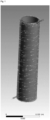
- the simulations were based on a Taylor-Couette reactor set-up as shown in Figure 1 with an inner rotor and outer stator, wherein the reaction mixture was introduced at one end of the reactor (upper right of the reactor in Figure 1 ) and was allowed to flow concentrically around the rotor within the reactor volume, and to spiral down to the reactor oulet (lower left or the reactor in Figure 1 ).
- the parameters used for the simulation are as follows:
- said velocity contour is indicative of an at least intermittently if not substantially turbulent flow regime of the reaction mixture along the entire length of the reactor.
- substantially no temperature gradient may be obtained under these simulation conditions, the temperature being around 500 K along the entire length of the reactor volume.
- Example 3 Simulation of a change of the reaction mixture from aqueous solution to gel
- the reaction mixture displays an irregular velocity profile along the first third of the reactor volume, wherein the velocity regularly oscillates between values of around 0.2 m ⁇ s -1 and values of around 0.8 m ⁇ s -1 , thus indicative of an at least intermittently if not substantially turbulent flow regime.
- Said velocity contour however diminishes to become constant at values of around 0.45 m ⁇ s -1 , which is then observed throughout the remaining length of the reactor volume down to the outlet and is again indicative of a laminar flow regime within that portion of the reactor volume.
- the first third of the reactor length is not heated and thus displays a temperature of 300 K, which is the temperature the reaction mixture has prior to entering the reactor.
- the second third displays a gradual increase to values of around 480 K, said temperature then being maintained in the last third of the reactor length down to the outlet.
- the reaction mixture in the last two thirds of the reactor volume displays a velocity and temperature contour resembling the results obtained in Example 1.
- Reference Example 1 Viscosity measurements performed on a reaction mixture for producing chabazite
- a reaction mixture for the synthesis of chabazite employing N,N,N-trimethylcyclohexylammonium hydroxide was prepared as described in WO 2013/182974 A1 .
- the viscosity characteristics of said reaction mixture were then measured under reaction conditions, wherein the mixture was place in a rotational viscometer (Anton Paar, Physica MCR301) using a pressurized cell with cylindrical geometry (DG35, 12/PR). After placing a sample of the reaction mixture in the measurement cell, it was pressurized with nitrogen gas to a pressure of 8 bar. The viscosity was then measured, wherein the sample was heated from room temperature at a reaction rate of 2°C per minute until 170°C and then held constantly at that temperature.
- the viscosity measurement of the crystallization of the reaction mixture confirms the evolution of the rheology of the reaction mixture during the preparation of a zeolitic material as simulated in Example 3.
Landscapes
- Chemical & Material Sciences (AREA)
- Organic Chemistry (AREA)
- Chemical Kinetics & Catalysis (AREA)
- Life Sciences & Earth Sciences (AREA)
- General Life Sciences & Earth Sciences (AREA)
- Geology (AREA)
- Engineering & Computer Science (AREA)
- Materials Engineering (AREA)
- Inorganic Chemistry (AREA)
- Organic Low-Molecular-Weight Compounds And Preparation Thereof (AREA)
- Catalysts (AREA)
- Silicates, Zeolites, And Molecular Sieves (AREA)
Description
- The present invention relates to a process for the preparation of a zeolitic material, as well as to a catalyst per se as obtainable or obtained according to said process. Furthermore, the present invention relates to the use of the zeolitic material, in particular as a catalyst.
- The synthesis of zeolitic materials from simple starting compounds involves a complex process of self organization which often necessitates special conditions such as elevated temperatures and/or pressure, wherein such reactions typically require the heating of starting materials under autogenous pressure for obtaining the zeolitic material after lengthy reaction times ranging from days to several weeks. Accordingly, due to the often harsh reaction conditions and the long reaction times, batch synthesis has long been the method of choice for synthesizing zeolitic materials. Batch reactions however present numerous limitations, in particular relative to the levels of space-time-yield which may be attained.
- Efforts have accordingly been invested in finding improved batch reaction procedures as well as alternative methodologies which offer advantages to the classical batch synthetic procedures employed for the synthesis of zeolitic materials. One method which has been investigated in this respect involves the use of continuous stirred-tank reactors wherein the fluid reagents are continuously introduced at the top of a tank reactor, and the effluent containing the solid reaction product is continuously removed from the bottom of the tank reactor. Although said methodologies eliminate the need to empty the reaction vessel between batch runs under non-continuous conditions, the reaction times necessary for crystallization remain lengthy.
- In view thereof, reactor geometries have been conceived which allow for a rapid synthesis of zeolitic materials. Thus,
US 2016/0115039 A1 relates to a method for the continuous production of a zeolite in a tubular reactor displaying a low ratio of the volume to the lateral surface area. Similarly, Liu et al. in Angew. Chem. Int. Ed. 2015, 54, 5683-5687 discloses a continuous synthesis of high-silica zeolite SSZ-13 employing very short reaction times. Ju, J. et al. in Chemical Engineering Journal 2006, 116, 115-121 as well as Vandermeersch, T. et al. in Microporous and Mesoporous Materials 2016, 226, 133-139, on the other hand, respectively disclose the rapid synthesis of micron sized NaA zeolite in a continuous flow reactor setup. Liu, Z. et al. in Chemistry of Materials 2014, 26, 2327-2331 concerns an ultrafast continuous-flow synthesis of crystalline microporous aluminophophate AlPO4-5. Slangen et al. "Continuous Synthesis of Zeolites using a Tubular Reactor", 12th International Zeolite Conference, Materials Research Society 1999 relates to the continuous syntheses of NaA zeolite, NaY zeolite, and silicalite-1 in a tubular reactor of 6 mm outer diameter (~3 mm inner diameter) and variable length. Bebon, C. et al. in Microporous and Mesoporous Materials 2002, 53, 13-20 concerns a method for the synthesis of zeolites employing a guide tube contained in an autoclave, wherein the reaction mixture is conveyed through the guide tube with the aid of an Archimedes screw placed within the guide tube along its axis.KR 2015/0093320 A EP 1504808 A1 relates to a rotating stirring and/or reaching device particularly suitable for mixing steps that require substantially narrow distribution of energy dissipation rate, in particular for reactors or mixers to be used in bio(chemical) reactions for the production of biologically active products for pharmaceutical applications. - For reactions which do not necessitate high pressure, microwave-assisted procedures have been investigated such as Bonaccorsi, L. et al. in Microporous and Mesoporous Materials 2008, 112, 481-493 which relates to the continuous synthesis of zeolite LTA. Similarly,
US 2001/0054549 A1 concerns a continuous process and apparatus for preparing inorganic materials employing microwaves. - Although considerable progress has been made relative to the reaction efficiency in view of the use of continuous stirred-tank and multiple stage reactors, progress made in view of the reduction of the reaction times has been limited to reactor geometries applied on a lab-scale level. Furthermore, efforts made with respect to the reduction of reaction times remain highly limited with respect to economically viable durations of operation due to the clogging of the reactor, in particular due to the pronounced changes in the rheology of the reaction mixture which occur during zeolite synthesis. More specifically, upon heating in a tubular reactor with laminar flow, the synthesis gel will typically show high shear rates in the region near the wall, whereas the core will show almost no shear rate due to the slow rate of heat transfer towards the core, in part due to an insulating effect of the synthesis gel in the region near the wall. As a result, the synthesis gel displays large temperature gradients from the wall region towards the core, and large residence distribution times are observed. In view of the severe inhomogeneous treatment of the synthesis gel resulting for this situation, very long reactors would need to be employed in order to obtain degrees of crystallization which are satisfactory.
- Thus, despite progress made with regard to the continuous synthesis of zeolitic materials, there remains a need for a process which avoids the problems of poor heat transfer and the ensuing inhomogeneous reaction conditions experienced by a synthesis gel in reactors.
- It was therefore an object of the present invention to provide an improved process for preparing a zeolitic material which allows for a homogenous shear rate and temperature gradient of the synthesis gel in a reactor, in particular on an industrial scale. Thus, it has surprisingly been found that depending on whether the reaction mixture displays a shear thinning or shear thickening rheology during the crystallization process, by using a flow regimen with a specific velocity profile in a reactor, it is possible to obtain an improved homogeneity with regard to the temperature and shear rate gradient within the synthesis gel in the direction of flow. In particular, it has quite unexpectedly been found that by generating a velocity profile of the reaction mixture within the reactor which is essentially opposite to the velocity profile generated by laminar flow of the same reaction mixture through a tubular reactor, an improved homogeneity is obtained for the rate of crystallization within the reactor mixture as well as with regard to the transport rate of the mixture within the reactor such as to avoid the considerable disadvantages of inhomogeneous crystallization and mass transfer incurred in the conventional synthesis of zeoliitc materials, in particular in continuous synthesis methodologies.
- Therefore, the present invention relates to a process for preparing a zeolitic material having a framework structure comprising YO2 and optionally comprising X2O3, wherein Y is Si or Si and Ti and X is Al, said process comprising
- (i) preparing a mixture comprising a source of YO2, optionally a source of X2O3, and a liquid solvent system;
- (ii) feeding the mixture prepared in (i) as the reaction mixture into a reactor;
- (iii) heating the reaction mixture in the reactor for obtaining a reacted mixture containing a zeolitic material having a framework structure comprising YO2 and optionally comprising X2O3; and
- (iv) collecting the reacted mixture obtained in (iii) containing the zeolitic material as the effluent from the reactor;
wherein the reactor is a Taylor-Couette reactor comprising an inner cylinder and an outer cylinder which are coaxially aligned. - In (iii), the reaction mixture is preferably subject to shearing such as to create a flow of the reaction mixture relative to the outer wall of the reactor with which the reaction mixture is in contact, and
wherein in (iii) in instances wherein the reaction mixture displays a shear thinning rheology (pseudoplastic rheology), the velocity profile v(r) of the reaction mixture in the direction of flow fulfills the condition according to (I):

- The straight line r is preferably perpendicular to the inner surface of the wall of the reactor in contact with the reaction mixture.
- Preferably, in (iii) in instances wherein the reaction mixture displays a shear thinning rheology (pseudoplastic rheology), the second derivative v"(r) of the velocity profile fulfills the condition according to (III):


- In instances wherein the reaction mixture displays a shear thinning rheology (pseudoplastic rheology), preferably the velocity profile v(r) of the reaction mixture in the direction of flow fulfills the condition according to (V):


- Preferably, in (iii) in instances wherein the reaction mixture displays a shear thinning rheology (pseudoplastic rheology), the second derivative v"(r) of the velocity profile fulfills the condition according to (VII):


- In (iii), preferably the flow regime in at least a portion P of the volume of the reactor is laminar, wherein the portion P is preferably an uninterrupted portion of the volume of the reactor. Preferably, in (iii) the Reynolds number (Re) in at least the portion P of the volume of the reactor containing the reaction mixture is 2,500 or less, more preferably of 2,000 or less, more preferably of 1,500 or less, more preferably of 1,000 or less, more preferably of 500 or less, more preferably of 300 or less, more preferably of 200 or less, more preferably of 100 or less, more preferably of 80 or less, more preferably of 60 or less, more preferably of 40 or less, more preferably of 20 or less, more preferably of 10 or less, more preferably of 5 or less, more preferably of 3 or less, and more preferably of 1 or less. The term Reynolds number (Re) as used herein means Re = uax · dgap/n; wherein uax is the axial velocity of the liquid used, n is the dynamic viscosity and dgap is the gap width in the reactor, preferably the gap width between rotating cylinders in the reactor; whereby axial is in the sense of being aligned with the rotating axis of the cylinders in the reactor.
- Preferably in (iii) the Taylor number (Ta), more preferably the tangential Taylor number, in at least the portion P of the volume of the reactor containing the reaction mixture fulfills the condition according to (III):

- Preferably the uninterrupted, portion P of the volume of the reactor preferably constitutes 5 to 100% of the total volume of the reactor containing the reaction mixture, more preferably 10 to 95%, more preferably 20 to 90%, more preferably 30 to 85%, more preferably 40 to 80%, more preferably 50 to 75%, and more preferably 60 to 70% of the total volume of the reactor containing the reaction mixture.
- Preferably, the reaction mixture displays a shear thinning rheology (pseudoplastic rheology) or wherein the reaction mixture displays a shear thickening rheology (dilatant rheology), wherein preferably the reaction mixture displays a shear thinning rheology (pseudoplastic rheology).
- As to step (iii), the mixture is heated to a temperature preferably in the range of from 100 to 300°C, more preferably of from 120 to 280°C, more preferably of from 140 to 260°C, more preferably of from 160 to 250°C, more preferably of from 180 to 240°C, more preferably of from 190 to 230°C, and more preferably of from 200 to 220°C.
- As to the reactor, the volume of the reactor containing the reaction mixture preferably is in the range of from 5cm3 to 1 m3, more preferably from 10 cm3 to 1 m3, more preferably from 20 cm3 to 0.5 m3, more preferably from 30 cm3 to 0.1 m3, more preferably from 50 cm3 to 0.05 m3, more preferably from 80 cm3 to 0.01 m3, more preferably from 100 to 5,000 cm3, more preferably from 120 to 3,000 cm3, more preferably from 150 to 1,000 cm3, more preferably from 200 to 700 cm3, more preferably from 230 to 500 cm3, and more preferably from 250 to 300 cm3. Preferably, the inner surface of the wall of the reactor in contact with the mixture is made of a metallic material, wherein the metallic material comprises one or more metals selected from the group consisting of Ta, Cr, Fe, Ni, Cu, Al, Mo, and combinations and/or alloys of two or more thereof, more preferably from the group consisting of Ta, Cr, Fe, Ni, Mo, and combinations and/or alloys of two or more thereof, preferably from the group consisting of Cr, Fe, Ni, Mo, and combinations and/or alloys of two or more thereof wherein preferably the metallic material comprises a nickel alloy, a nickel-molybdenum alloy, and more preferably a nickel-molybdenum-chromium alloy. Preferably, the inner surface of the wall of the reactor in contact with the mixture is lined with an organic polymer material, wherein the organic polymer material more preferably comprises one or more polymers selected from the group consisting of fluorinated polyalkylenes and mixtures of two or more thereof, preferably from the group consisting of (C2-C3)polyalkylenes and mixtures of two or more thereof, preferably from the group consisting of fluorinated polyethylenes and mixtures of two or more thereof, wherein more preferably the polymer material comprises poly(tetrafluoroethylene), wherein more preferably the inner wall of the reactor is lined with poly(tetrafluoroethylene).
- As to step (iii), preferably in (iii) the reaction mixture is heated under autogenous pressure, wherein preferably the pressure is in the range of from 0.1 to 9 M Pa, more preferably in the range of from 0.5 to 7 MPa, more preferably from 0.8 to 5 MPa, more preferably from 1.3 to 3 MPa, more preferably from 1.4 to 2 MPa, more preferably from 1.5 to 1.7 MPa.
- The reactor preferably consists of a single stage. Preferably, no matter is added to and/or removed from the reaction mixture during its passage through the reactor in (iii), wherein more preferably no matter is added, wherein more preferably no matter is added and no matter is removed from the reaction mixture during its passage through the reactor in (iii).
- Preferably, prior to (ii) the mixture prepared in (i) is aged at a temperature in the range of from 40 to 120°C, more preferably from 50 to 110°C, more preferably from 60 to 105°C, more preferably from 70 to 100°C, more preferably from 75 to 95°C, and more preferably from 80 to 90°C. Preferably, in (i) and prior to (ii) the mixture prepared in (i) is not heated to a temperature of 40°C or greater, more preferably of 35°C or greater, more preferably of 30°C or greater, wherein more preferably in (i) and prior to (ii) the mixture prepared in (i) is not subject to a heating step. Preferably prior to (ii) the mixture prepared in (i) is aged for a duration ranging from 1 to 72 h, more preferably from 6 to 62 h, more preferably from 12 to 56 h, more preferably from 24 to 50 h, more preferably from 36 to 44 h, and more preferably from 38 to 42 h.
- The mixture prepared in (i) is preferably directly fed into the reactor in (ii), wherein while being fed to the reactor in (ii), the mixture prepared in (i) is pre-heated, preferably to a temperature in the range of from 100 to 300°C, more preferably of from 100 to 280°C, more preferably of from 140 to 260°C, more preferably of from 160 to 250°C, more preferably of from 180 to 240°C, more preferably of from 190 to 230°C, and more preferably of from 200 to 220°C.
- As to collecting of the reacted mixture in (iv), this preferably includes quenching the reacted mixture effluent exiting the reactor in (iii) with a liquid comprising one or more solvents and/or via expansion of the reacted mixture effluent. Preferably, the liquid for quenching comprises one or more solvents selected from the group consisting of polar protic solvents and mixtures thereof,
- more preferably from the group consisting of n-butanol, isopropanol, propanol, ethanol, methanol, water, and mixtures thereof,
- more preferably from the group consisting of ethanol, methanol, water, and mixtures thereof, wherein more preferably the liquid comprises water, and wherein more preferably water is used as the liquid, preferably deionized water.
- In the context of the present invention, the process preferably further comprises
- (v) isolating the zeolitic material obtained in (iii) or (iv);
and/or, preferably and, - (vi) washing the zeolitic material obtained in (iii), (iv) or (v);
and/or, preferably and, - (vii) drying the zeolitic material obtained in (iii), (iv), (v), or (vi);
and/or, preferably and, - (viii) calcining the zeolitic material obtained in (iii), (iv), (v), (vi), or (vii).
- If step (v) is carried out, in (v) preferably the zeolitic material is isolated from the reacted mixture obtained from (iii) or (iv) by means of filtration, centrifugation and/or decantation methods, more preferably by means of microfiltration and/or ultrafiltration, wherein more preferably microfiltration and/or ultrafiltration is achieved by membrane filtration. The supernatant obtained from the isolation of the zeolitic material in (v), preferably is recycled to (i) and/or (ii), more preferably to (i).
- If step (vii) is carried out, in (vii) preferably the zeolitic material is dried by means of microwave radiation and/or flash drying of the zeolitic material obtained in (iii), (iv), (v), or (vi).
- If steps (vii) and (viii) are carried out, drying in (vii) and calcination in (viii) preferably is achieved by one or more steps of calcining the zeolitic material obtained in (iii), (iv), (v), or (vi).
- If step (v) is carried out, in (v) isolating the zeolitic material preferably includes a step of spray-drying the zeolitic material obtained in (iii) or (iv),
and/or
wherein in (vii) drying of the zeolitic material includes a step of spray-drying the zeolitic material obtained in (iii), (iv), (v), or (vi). - If step (vii) is carried out, drying in (vii) is preferably effected at a temperature in the range from 50 to 220°C, more preferably from 70 to 180°C, more preferably from 80 to 150°C, more preferably from 90 to 130°C, more preferably from 100 to 125°C, and more preferably from 110 to 120°C.
- If step (viii) is carried out, the calcining in (viii) is preferably effected at a temperature in the range from 300 to 800°C, more preferably from 350 to 750°C, more preferably from 400 to 725°C, more preferably from 450 to 700°C, more preferably from 500 to 675°C, and more preferably from 550 to 650°C.
- Generally, it is possible that according to the process of the present invention that seed crystals are comprised therein. Preferably, the mixture prepared in (i) further comprises seed crystals, wherein the amount of seed crystals in the mixture prepared in (i) preferably ranges from 0.1 to 20 wt.-% based on 100 wt.-% of Y calculated as YO2 contained in the mixture prepared in (i), more preferably from 0.3 to 10 wt.-%, more preferably from 0.5 to 5 wt.-%, more preferably from 1 to 3 wt.-%, and even more preferably from 1.5 to 2.5 wt.-% based on 100 wt.-% of Y calculated as YO2 contained in the mixture prepared in (i). Preferably, the seed crystals comprise one or more zeolites having a framework structure selected from the group consisting of AEI, AFX, ANA, BEA, BEC, CAN, CHA, CDO, EMT, ERI, EUO, FAU, FER, GME, HEU, ITH, ITW, KFI, LEV, MEI, MEL, MFI, MOR, MTN, MWW, OFF, RRO, RTH, SAV, SFW, SZR, and TON, including mixed structures of two or more thereof, more preferably from the group consisting of CAN, AEI, EMT, SAV, SZR, KFI, ERI, OFF, RTH, GME, AFX, SFW, BEA, CHA, FAU, FER, HEU, LEV, MEI, MEL, MFI, MOR, and MWW, including mixed structures of two or more thereof, more preferably from the group consisting of AEI, AFX, BEA, CHA, ERI, FAU, FER, GME, LEV, MEL, MFI, MOR, and MWW, including mixed structures of two or more thereof, more preferably from the group consisting of AEI, AFX, BEA, CHA, ERI, FER, GME, MEL, MFI, MOR, and MWW, including mixed structures of two or more thereof, more preferably from the group consisting of AEI, BEA, CHA, ERI, MFI, and MWW, including mixed structures of two or more thereof, and more preferably from the group consisting of AEI, BEA, CHA, MFI, and MWW, including mixed structures of two or more thereof, wherein more preferably the seed crystals comprise one or more zeolites having the CHA and/or AEI framework structure.
- Generally, it is possible that according to the process of the present invention that organotemplates are comprised therein. Preferably, the mixture prepared in (i) further comprises one or more organotemplates. The one or more organotemplates are preferably selected from the group consisting of tetraalkylammonium compounds, 1N-alkyl-3-quinuclidinol, or N,N,N-trialkyl-exo-aminonorbornane, and mixtures of two or more thereof,
- more preferably from the group consisting of 1-adamantyltri(C1-C3)alkyl-ammonium compounds, N,N,N-tri(C1-C2)alkyl-(C5-C6)cycloalkylammonium compounds, N,N,N-trimethyl-N-benzylammonium compounds, and mixtures of two or more thereof,
- more preferably from the group consisting of 1-adamantyltri(C1-C2)alkyl-ammonium compounds, N,N,N-tri(C1-C2)alkyl-cyclopentylammonium compounds, N,N,N-tri(C1-C2)alkyl-cyclohexylammonium compounds, and mixtures of two or more thereof,
- more preferably from the group consisting of 1-adamantyltriethyl-ammonium compounds, 1-adamantyldiethyl-methylalkylammonium compounds, 1-adamantylethyl-dimethylammonium compounds, 1-adamantyltrimethylammonium compounds, N,N,N-triethyl-cyclohexylammonium compounds, N,N-diethyl-N -methyl-cyclohexylammonium compounds, N,N-dimethyl-N -ethyl-cyclohexylammonium compounds, N,N,N -trimethyl-cyclohexylammonium compounds, and mixtures of two or more thereof,
- wherein more preferably the one or more organotemplates comprises one or more 1-adamantyltrimethylammonium compounds and/or one or more N,N,N -trimethyl-cyclohexylammonium compounds,
- wherein more preferably the one or more organotemplates comprises one or more N,N,N - trimethyl-cyclohexylammonium compounds. Preferably, independently of one another the tetraalkylammonium compounds are salts, more preferably one or more salts selected from the group consisting of halides, preferably chloride and/or bromide, more preferably chloride, hydroxide, sulfate, nitrate, phosphate, acetate, and mixtures of two or more thereof, more preferably from the group consisting of chloride, hydroxide, sulfate, and mixtures of two or more thereof, wherein more preferably the one or more tetraalkylammonium compounds are tetraalkylammonium hydroxides and/or chlorides, and even more preferably tetraalkylammonium hydroxides.
- Alternatively, the one or more organotemplates are preferably selected from the group consisting of tetraalkylphosphonium compounds, more preferably from the group consisting of tetra(C1-C6)alkylphosphonium compounds, more preferably from the group consisting of tetra(C1-C5)alkylphosphonium compounds, more preferably from the group consisting of tetra(C1-C4)alkylphosphonium compounds, more preferably from the group consisting of tetra(C2-C3)alkylphosphonium compounds,more preferably from the group consisting of tetramethylphosphonium compounds, ethyltrimethylphosphonium compounds, diethyldimethylphosphonium compounds, methyltriethylphosphonium compounds, tetraethylphosphonium compounds, and mixtures of two or more thereof, wherein more preferably the one or more organotemplates are selected from the group consisting of tetraethylphosphonium compounds.
- Preferably, the mixture prepared in (i) and heated in (iii) does not comprise one or more organotemplates.
- In the context of the present invention Y is Si or Si and Ti. Generally, according to (i), any suitable source of YO2 can be used. Preferably, the source of YO2 comprises one or more compounds selected from the group consisting of fumed silica, silica hydrosols, reactive amorphous solid silicas, silica gel, silicic acid, water glass, sodium metasilicate hydrate, sesquisilicate, disilicate, colloidal silica, silicic acid esters, and mixtures of two or more thereof, more preferably from the group consisting of fumed silica, silica hydrosols, reactive amorphous solid silicas, silica gel, silicic acid, colloidal silica, silicic acid esters, and mixtures of two or more thereof, more preferably from the group consisting of fumed silica, silica hydrosols, reactive amorphous solid silicas, silica gel, colloidal silica, and mixtures of two or more thereof, wherein even more preferably the source of YO2 comprises fumed silica and/or colloidal silica, preferably colloidal silica.
- In the context of the present invention X is Al. Generally, according to (i), any suitable source of X2O3 can be used. Preferably, the source of X2O3 comprises one or more compounds selected from the group consisting of alumina, aluminates, aluminum salts, and mixtures of two or more thereof, more preferably from the group consisting of alumina, aluminum salts, and mixtures of two or more thereof, more preferably from the group consisting of alumina, aluminum tri(C1-C5)alkoxide, AlO(OH), Al(OH)3, aluminum halides, preferably aluminum fluoride and/or chloride and/or bromide, and more preferably aluminum fluoride and/or chloride, aluminum sulfate, aluminum phosphate, aluminum fluorosilicate, [Al13O4(OH)24(H2O)12]7+ containing salts, alkali metal aluminates, and mixtures of two or more thereof, more preferably from the group consisting of aluminum tri(C2-C4)alkoxide, AIO(OH), Al(OH)3, aluminum chloride, aluminum sulfate, aluminum phosphate, [Al13O4(OH)24(H2O)12]7+ containing salts, sodium aluminate, potassium aluminate, and mixtures of two or more thereof, more preferably from the group consisting of aluminum tri(C2-C3)alkoxide, AlO(OH), Al(OH)3, aluminum chloride, aluminum sulfate, [Al13O4(OH)24(H2O)12]7+ containing salts, sodium aluminate, and mixtures of two or more thereof, more preferably from the group consisting of aluminum tripropoxides, AIO(OH), aluminum sulfate, [Al13O4(OH)24(H2O)12]7+ containing salts, sodium aluminate, and mixtures of two or more thereof, and more preferably from the group consisting of aluminum tripropoxides, AIO(OH), Al(OH)3, aluminum sulfate, sodium aluminate, and mixtures of two or more thereof.
- Preferably, the mixture prepared in (i) further comprises at least one source for OH-, wherein said at least one source for OH- preferably comprises a metal hydroxide, more preferably a hydroxide of an alkali metal M, more preferably sodium and/or potassium hydroxide, and more preferably sodium hydroxide.
- In the mixture prepared in (i), comprising a source of YO2, optionally a source of X2O3, and a liquid solvent system, the YO2 : X2O3 molar ratio of the mixture prepared in (i) is not subject to any specific restrictions. Preferably, the YO2 : X2O3 molar ratio of the mixture prepared in (i) ranges from 1 to 1,000, more preferably from 2 to 500, more preferably from 4 to 200, more preferably from 5 to 150, more preferably from 20 to 100, more preferably from 30 to 80, more preferably from 40 to 60, and even more preferably from 45 to 55.
- Preferably, the liquid solvent system in the mixture prepared in (i) comprises one or more solvents, wherein the liquid solvent system preferably comprises one or more solvents selected from the group consisting of polar protic solvents and mixtures thereof,
- more preferably from the group consisting of n-butanol, isopropanol, propanol, ethanol, methanol, water, and mixtures thereof,
- more preferably from the group consisting of ethanol, methanol, water, and mixtures thereof, wherein more preferably the liquid solvent system comprises water, and wherein more preferably water is used as the liquid solvent system, preferably deionized water. Preferably, in (i) the liquid solvent system comprises water, wherein the H2O : YO2 molar ratio of the mixture prepared in (i) preferably ranges from 1 to 400, more preferably from 1 to 300, more preferably from 2 to 200, more preferably from 2 to 150, more preferably from 2 to 100, more preferably from 3 to 50, more preferably from 4 to 30, more preferably from 4.5 to 20, more preferably from 5 to 15, more preferably from 5.5 to 12, and even more preferably from 6 to 10.
- As to step (iii), it is preferred that the zeolitic material obtained in (iii) has a framework structure selected from the group consisting of AEI, AFX, ANA, BEA, BEC, CAN, CHA, CDO, EMT, ERI, EUO, FAU, FER, GME, HEU, ITH, ITW, KFI, LEV, MEI, MEL, MFI, MOR, MTN, MWW, OFF, RRO, RTH, SAV, SFW, SZR, and TON, including mixed structures of two or more thereof, more preferably from the group consisting of CAN, AEI, EMT, SAV, SZR, KFI, ERI, OFF, RTH, GME, AFX, SFW, BEA, CHA, FAU, FER, HEU, LEV, MEI, MEL, MFI, MOR, and MWW, including mixed structures of two or more thereof, more preferably from the group consisting of BEA, CHA, FAU, FER, GME, LEV, MFI, MOR, and MWW, including mixed structures of two or more thereof, more preferably from the group consisting of BEA, CHA, GME, MFI, MOR, and MWW, including mixed structures of two or more thereof, and more preferably from the group consisting of BEA, CHA, MFI, and MWW, including mixed structures of two or more thereof, wherein more preferably the zeolitic material obtained in (iii) has the CHA and/or BEA framework structure, preferably the CHA framework structure.
- Preferably, the mixture prepared in (i) and heated in (iii) consists of a single liquid phase optionally containing a solid phase. Preferably, the mixture heated in (iii) in the reactor is mechanically agitated, wherein more preferably mechanical agitation is achieved by movable parts contained in the reactor.
- Preferably, the Taylor-Couette reactor has a rotor-stator set-up, with the outer cylinder as the stator. Preferably, the two coaxial cylinders rotate at a speed in the range of 5 to 5,000 rpm relative to each other, more preferably of from 10 to 3,000 rpm, more preferably of from 30 to 2,500 rpm, more preferably of from 50 to 2,000 rpm, more preferably of from 100 to 1,500 rpm, more preferably of from 150 to 1,200 rpm, more preferably of from 200 to 1,000 rpm, more preferably of from 250 to 800 rpm, more preferably of from 300 to 700 rpm, more preferably of from 350 to 650 rpm, more preferably of from 400 to 600 rpm, and more preferably of from 450 to 550 rpm. Preferably, the gap between the two coaxial cylinders is in the range of from 0.3 to 50 cm, more preferably of from 0.4 to 30 cm, more preferably of from 0.5 to 25 cm, more preferably of from 0.6 to 20 cm, more preferably of from 0.6 to 15 cm, more preferably of from 0.7 to 10 cm, more preferably of from 0.7 to 5 cm, more preferably of from 0.8 to 3 cm, more preferably of from 0.8 to 2 cm, more preferably of from 0.9 to 1.5 cm, more preferably of from 0.9 to 1.2 cm, and more preferably of from 1.0 to 1.1 cm. Preferably, the diameter of the inner cylinder is in the range of from 0.5 to 100 cm, more preferably of from, 1 to 50 cm, more preferably of from 1.5 to 30 cm, more preferably of from 2 to 20 cm, more preferably of from 2.5 to 15 cm, more preferably of from 3 to 10 cm, more preferably of from 3.5 to 8 cm, more preferably of from 4 to 7 cm, more preferably of from 4.5 to 6 cm, and more preferably of from 5 to 5.5 cm. The length of the two coaxial cylinders is preferably in the range of from 5 to 500 cm, more preferably of from 8 to 300 cm, more preferably of from 10 to 200 cm, more preferably of from 12 to 150 cm, more preferably of from 15 to 100 cm, more preferably of from 18 to 80 cm, more preferably of from 20 to 50 cm, more preferably of from 23 to 35 cm, and more preferably of from 25 to 30 cm. Preferably, the inner and/or the outer cylinder, and more preferably the outer cylinder, is heated to a temperature in the range of from 120 to 310°C, preferably of from 140 to 290°C, more preferably of from 160 to 270°C, more preferably of from 180 to 260°C, more preferably of from 200 to 250°C, more preferably of from 210 to 240°C, and more preferably of from 220 to 230°C.
- Generally, it is possible that the process of the present invention may be conducted in a continuous mode or in a batch mode. Preferably, the feeding of the mixture in (ii) and the collecting of the reacted mixture in (iv) are conducted in a continuous mode and/or in a batch mode, more preferably in a continuous mode. Preferably, the process is conducted in a continuous mode and/or in a batch mode, more preferably in a continuous mode. The feeding of the mixture in (ii) and the collecting of the reacted mixture in (iv) are preferably conducted in a continuous mode, and the liquid hourly space velocity is in the range of from 0.3 to 250 h-1, more preferably from 0.5 to 150 h-1, more preferably from 1 to 100 h-1, more preferably from 2 to 70 h-1, more preferably from 5 to 50 h-1, more preferably from 8 to 30 h-1, more preferably from 10 to 20 h-1, and more preferably from 12 to 14 h-1. Preferably, in (ii) the mixture is continuously fed into the reactor for a duration of at least 1 h to 10 years, and more preferably for a duration ranging from 6 h to 8 years, more preferably from 12 h to 7 years, more preferably from 1 day to 6 years, more preferably from 7 days to 5 years, more preferably from 15 days to 4 years, more preferably from 1 month to 3.5 years, more preferably from 2 months to 3 years, more preferably from 4 months to 2.5 years, more preferably from 6 months to 2 years, more preferably from 8 months to 18 months, and more preferably from 10 to 14 months.
-
- Figure 1
- displays the general set-up of the Taylor-Couette reactor wherein the inlet for the reaction mixture is depicted at the upper right portion of the reactor and the outlet is depicted at the lower left portion of the reactor. In the figure, the arrows describe the incremental direction of flow of the reaction mixture in the gap between the inner rotor of the reactor depicted as a hollow tube, and the outer mantel (stator) depicted as a transparent shell for displaying the reactor volume between rotor and stator. The scale at the bottom of the figure displays the dimensions of the reactor used for the simulation in meters.
- Figure 2
- displays the rheology of the reaction mixture used in for the simulation in the experimental section, wherein the viscosity in Pa · s is plotted along the abscissa, and the shear rate in s-1 is plotted along the ordinate. In the figure, the function of the viscosity behavior in dependence on the shear rate is shown.
- Figure 3
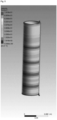
- displays the velocity contour of the reaction mixture in the Taylor-Couette reactor for the simulation of Example 1, wherein the scale in the figure indicates the velocity in m · s-1, which ranges from 0 to 0.6177 m · s-1. The scale at the bottom of the figure displays the dimensions of the reactor used for the simulation in meters.
- Figures 4, 6, and 8
- display the temperature contour of the reaction mixture in the Taylor-Couette reactor for the simulation of Examples 1, 2, and 3, respectively, wherein the scale in the figure indicates the temperature in degrees kelvin (K), which ranges from 300 to 500 K. The scale at the bottom of the figure displays the dimensions of the reactor used for the simulation in meters.
- Figure 5
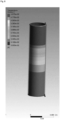
- displays the velocity contour of the reaction mixture in the Taylor-Couette reactor for the simulation of Example 2, wherein the scale in the figure indicates the velocity in m · s-1, which ranges from 0 to 0.7616 m · s-1. The scale at the bottom of the figure displays the dimensions of the reactor used for the simulation in meters.
- Figure 7
- displays the velocity contour of the reaction mixture in the Taylor-Couette reactor for the simulation of Example 3, wherein the scale in the figure indicates the velocity in m · s-1, which ranges from 0 to 0.82965 m · s-1. The scale at the bottom of the figure displays the dimensions of the reactor used for the simulation in meters.
- Figure 9
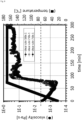
- displays the results of the viscosity measurements obtained in Reference Example 1 for different shear rates. In the figure, temperature measurement points are displayed with "■" and the viscosity measurement points with "●", wherein the temperature values in °C are plotted along the right abscissa, and the viscosity values in Pa · s are plotted along the left abscissa. The duration of the viscosity measurement in minutes is plotted along the ordinate. In the legend, the different viscosity measurement points for shear rates of 250, 500, and 750 s-1 are indicated, wherein the measurement for the shear rate of 250 s-1 was interrupted after 119 minutes, and the measurement for the shear rate of 750 s-1 was interrupted after 142 minutes. The dotted line in the figure indicates the viscosity level of the reaction mixture at the beginning of the measurement prior to heating.
- The experiments described herein were conducted with the simulation program Ansys® Fluent® v17.0.0. The simulations were based on a Taylor-Couette reactor set-up as shown in
Figure 1 with an inner rotor and outer stator, wherein the reaction mixture was introduced at one end of the reactor (upper right of the reactor inFigure 1 ) and was allowed to flow concentrically around the rotor within the reactor volume, and to spiral down to the reactor oulet (lower left or the reactor inFigure 1 ). The parameters used for the simulation are as follows: - Cylinder geometry:
- Length = 25cm
- Dinner = 5cm
- Douter = 6cm
- Volume = 0.00027 m3, Area = 0.09 m2
- Target reaction time:
- Tau = 5 min (300 s)
- Feed = 0.6 g/s (36 ml/min)
- Temperatures:
- Wall 500 K (227°C)
- Feed 300 K (27°C)
- Pressure Drop: 1550 Pa
- Material Properties (Non-newtonian Behaviour):
- Consistency Index 1.1
- Power-Law Index 0.252
- The viscosity characteristics of the reaction mixture used in the simulations is displayed in
Figure 2 . - A simulation was conducted with the reaction set-up described above, wherein the shear rate of the Taylor-Couette reactor was set such that the Reynolds number (Re) of the reaction mixture was Re = 2.3, and the Taylor number (Ta) of the reaction mixture was Ta = 1. The velocity contour obtained according to the simulation is displayed in
Figure 3 , and the temperature contour is shown inFigure 4 . Thus, as may be taken from the results of the simulation displayed inFigure 3 , under the conditions chosen the reaction mixture displays a substantially homogenous velocity profile along the entire length of the reactor volume, with values around 0.6 m · s-1, which indicative of a laminar flow regime of the reaction mixture substantially along the entire length of the reactor. As may be taken from the temperature contour displayed inFigure 4 , the reaction mixture displays a gradual increase in temperature from the upper inlet region displaying temperature values of around 350 K to the lower outlet region displaying values of around 460 K. - A further simulation was conducted with the reaction set-up described above, wherein the shear rate of the Taylor-Couette reactor was set such that the Reynolds number (Re) of the reaction mixture was Re = 2.6, and the Taylor number (Ta) of the reaction mixture was Ta = 111. The velocity contour obtained according to the simulation is displayed in
Figure 5 , and the temperature contour is shown inFigure 6 . Thus, as may be taken from the results of the simulation displayed inFigure 5 , under the conditions chosen the reaction mixture displays an irregular velocity profile along the length of the reactor volume, wherein the velocity regularly oscillates between values of around 0.4 m · s-1 and values of around 0.7 m · s-1. As opposed to the results obtained in Example 1, said velocity contour is indicative of an at least intermittently if not substantially turbulent flow regime of the reaction mixture along the entire length of the reactor. Furthermore, as may be taken from the temperature contour displayed inFigure 6 , as opposed to the results obtained in Example 1, substantially no temperature gradient may be obtained under these simulation conditions, the temperature being around 500 K along the entire length of the reactor volume. - An additional simulation was conducted, wherein the rheology of the reaction mixture was varied to simulate a transition from the rheology of an aqueous solution to the rheology of a gel as is typically encountered during the course of crystallization of zeolitic materials from an aqueous solution or slurry containing the precursor compounds. In particular, the rheology was simulated such that in the first third of the reactor volume from the inlet end displayed a rheology typical of an aqueous solution, and the last two thirds of the reactor volume down to the outlet of the reactor display a rheology typical of a gel. For this purpose, no heating of the reaction mixture was applied in the first third of the reactor volume, heating only being applied to the last two thirds down to the outlet. Furthermore, the feed of the reaction mixture was increased to 60 ml/min, and the rotation speed
- Thus, as may be taken from the results of the simulation displayed in
Figure 7 , under the conditions chosen the reaction mixture displays an irregular velocity profile along the first third of the reactor volume, wherein the velocity regularly oscillates between values of around 0.2 m · s-1 and values of around 0.8 m · s-1, thus indicative of an at least intermittently if not substantially turbulent flow regime. Said velocity contour however diminishes to become constant at values of around 0.45 m · s-1, which is then observed throughout the remaining length of the reactor volume down to the outlet and is again indicative of a laminar flow regime within that portion of the reactor volume. Furthermore, as may be taken from the temperature contour displayed inFigure 8 , the first third of the reactor length is not heated and thus displays a temperature of 300 K, which is the temperature the reaction mixture has prior to entering the reactor. In the last two thirds of the reactor length in which the reaction mixture is heated, the second third displays a gradual increase to values of around 480 K, said temperature then being maintained in the last third of the reactor length down to the outlet. Thus, the reaction mixture in the last two thirds of the reactor volume displays a velocity and temperature contour resembling the results obtained in Example 1. - A reaction mixture for the synthesis of chabazite employing N,N,N-trimethylcyclohexylammonium hydroxide was prepared as described in
WO 2013/182974 A1 . The viscosity characteristics of said reaction mixture were then measured under reaction conditions, wherein the mixture was place in a rotational viscometer (Anton Paar, Physica MCR301) using a pressurized cell with cylindrical geometry (DG35, 12/PR). After placing a sample of the reaction mixture in the measurement cell, it was pressurized with nitrogen gas to a pressure of 8 bar. The viscosity was then measured, wherein the sample was heated from room temperature at a reaction rate of 2°C per minute until 170°C and then held constantly at that temperature. Three samples were measured at respective shear rates of 250 s-1, 500 s-1, and 750 s-1, wherein the measurement for the shear rate of 250 s-1 was interrupted after 119 minutes, the measurement for the shear rate of 750 s-1 was interrupted after 142 minutes, and the shear rate of 500 s-1 was interrupted after 300 minutes. The results of the measurement are displayed inFigure 9 . Thus, as may be taken from the results, the viscosity gradually decreases during the intial heating stage, wherein when reaching the maximum temperature it suddenly increases considerably, and then levels out until the end of the crystallization reaction, at which a further considerable increase of the viscosity is observed. - Accordingly, the viscosity measurement of the crystallization of the reaction mixture confirms the evolution of the rheology of the reaction mixture during the preparation of a zeolitic material as simulated in Example 3.
-
-
US 2016/0115039 A1 - Liu et al. in Angew. Chem. Int. Ed. 2015, 54, 5683-5687
- Ju, J. et al. in Chemical Engineering Journal 2006, 116, 115-121
- Vandermeersch, T. et al. in Microporous and Mesoporous Materials 2016, 226, 133-139
- Liu, Z. et al. in Chemistry of Materials 2014, 26, 2327-2331
- Slangen et al. "Continuous Synthesis of Zeolites using a Tubular Reactor", 12th International Zeolite Conference, Materials Research Society 1999
- Bonaccorsi, L. et al. in Microporous and Mesoporous Materials 2008, 112, 481-493
-
US 2001/0054549 A1 -
KR 2015/0093320 A -
EP 1504808 A1 - Bebon, C. et al. in Microporous and Mesoporous Materials 2002, 53, 13-20
Claims (12)
- A process for preparing a zeolitic material having a framework structure comprising YO2 and optionally comprising X2O3, wherein Y is Si or Si and Ti, and wherein X is Al, said process comprising(i) preparing a mixture comprising a source of YO2, optionally a source of X2O3, and a liquid solvent system;(ii) feeding the mixture prepared in (i) as the reaction mixture into a reactor;(iii) heating the reaction mixture in the reactor for obtaining a reacted mixture containing a zeolitic material having a framework structure comprising YO2 and optionally comprising X2O3; and(iv) collecting the reacted mixture obtained in (iii) containing the zeolitic material as the effluent from the reactor;wherein the reactor is a Taylor-Couette reactor comprising an inner cylinder and an outer cylinder which are coaxially aligned.
- The process of claim 1, wherein the Taylor-Couette reactor has a rotor-stator set-up, with the outer cylinder as the stator.
- The process of claim 1 or 2, wherein in (iii) the reaction mixture is subject to shearing such as to create a flow of the reaction mixture relative to the outer wall of the reactor with which the reaction mixture is in contact, andwherein in (iii) in instances wherein the reaction mixture displays a shear thinning rheology (pseudoplastic rheology), the velocity profile v(r) of the reaction mixture in the direction of flow fulfills the condition according to (I):
 and wherein in (iii) in instances wherein the reaction mixture displays a shear thickening rheology (dilatant rheology), the velocity profile v(r) of the reaction mixture in the direction of flow fulfills the condition according to (II):
 wherein r defines the length of a straight line on the cross-sectional area of the reactor space perpendicular to the flow direction of the reaction mixture in the reactor, wherein said straight line extends from a first point at the inner surface of the wall of the reactor in contact with the mixture, wherein at said first point r0 is defined as 0 and v exhibits its minimum value (vmin = v(r0)), to a second point where r is defined as rmax and v exhibits its maximum value (vmax = v(rmax)), wherein r1 = rmax/x, and x = 5.
 - The process of claim 3, wherein the straight line r is perpendicular to the inner surface of the wall of the reactor in contact with the reaction mixture.
- The process of claim 3 or 4, wherein in (iii) in instances wherein the reaction mixture displays a shear thinning rheology (pseudoplastic rheology), the second derivative v" (r) of the velocity profile fulfills the condition according to (III):


- The process of any of claims 1 to 5, wherein in (iii) the flow regime in at least a portion P of the volume of the reactor is laminar.
- The process of any of claims 1 to 6, wherein in (iii) the Reynolds number (Re) in at least the portion P of the volume of the reactor containing the reaction mixture is 2,500 or less.
- The process of claim 7, wherein in (iii) the Taylor number (Ta), in at least the portion P of the volume of the reactor containing the reaction mixture fulfills the condition according to (III):

- The process of any of claims 1 to 8, wherein the mixture is heated to a temperature in the range of from 100 to 300°C.
- The process of any of claims 1 to 9, wherein the volume of the reactor containing the reaction mixture is in the range of from 5cm3 to 1 m3.
- The process of any of claims 1 to 10, wherein in (iii) the reaction mixture is heated under autogenous pressure.
- The process of any of claims 1 to 11, wherein the process is conducted in a continuous mode and/or in a batch mode.
Applications Claiming Priority (2)
| Application Number | Priority Date | Filing Date | Title |
|---|---|---|---|
| EP17203017 | 2017-11-22 | ||
| PCT/EP2018/082212 WO2019101854A1 (en) | 2017-11-22 | 2018-11-22 | Zeolite synthesis in a reactor with controlled velocity profile |
Publications (4)
| Publication Number | Publication Date |
|---|---|
| EP3713668A1 EP3713668A1 (en) | 2020-09-30 |
| EP3713668B1 true EP3713668B1 (en) | 2023-06-07 |
| EP3713668C0 EP3713668C0 (en) | 2023-06-07 |
| EP3713668B8 EP3713668B8 (en) | 2023-08-09 |
Family
ID=60484131
Family Applications (1)
| Application Number | Title | Priority Date | Filing Date |
|---|---|---|---|
| EP18803716.2A Active EP3713668B8 (en) | 2017-11-22 | 2018-11-22 | Zeolite synthesis in a reactor with controlled velocity profile |
Country Status (8)
| Country | Link |
|---|---|
| US (1) | US11897778B2 (en) |
| EP (1) | EP3713668B8 (en) |
| JP (1) | JP7383613B2 (en) |
| KR (1) | KR102650791B1 (en) |
| CN (1) | CN111372676B (en) |
| ES (1) | ES2954327T3 (en) |
| WO (1) | WO2019101854A1 (en) |
| ZA (1) | ZA202002456B (en) |
Families Citing this family (5)
| Publication number | Priority date | Publication date | Assignee | Title |
|---|---|---|---|---|
| CN114423711A (en) * | 2019-09-20 | 2022-04-29 | 巴斯夫欧洲公司 | Synthesis and use of zeolitic materials having an ITH framework structure type |
| CN113181853B (en) * | 2021-06-08 | 2022-10-18 | 天津科技大学 | A kind of microchannel reaction mixing device and mixing method with cross-shaped mixing structure |
| WO2022263436A1 (en) | 2021-06-14 | 2022-12-22 | Basf Se | Zeolite synthesis in a continuous flow reactor with a pulsatile flow regime |
| GB2625824A (en) * | 2022-12-30 | 2024-07-03 | Promethean Particles Ltd | Mixing reactors |
| WO2025199095A1 (en) * | 2024-03-19 | 2025-09-25 | Basf Mobile Emissions Catalysts Llc | Synthesis of eri rich zeolitic phase using trimethylcyclohexylammonium cation, its derivatives and mixtures |
Family Cites Families (15)
| Publication number | Priority date | Publication date | Assignee | Title |
|---|---|---|---|---|
| KR100411194B1 (en) | 2000-11-03 | 2003-12-18 | 한국화학연구원 | Continuous microwave synthesis of inorganic materials and its divice |
| US7572414B2 (en) * | 2001-10-09 | 2009-08-11 | Lummus Technology Inc. | Modular system and method for the catalytic treatment of a gas stream |
| US7220341B2 (en) * | 2002-03-11 | 2007-05-22 | Exxonmobil Chemical Patents Inc. | Controlling solids flow in a gas-solids reactor |
| EP1504808A1 (en) | 2003-08-08 | 2005-02-09 | ETH Zürich | Rotating stirring device with substantially narrow distribution of energy dissipation rate |
| WO2005063624A1 (en) * | 2003-12-23 | 2005-07-14 | Exxonmobil Chemical Patents Inc. | Aei-type zeolite, its synthesis and its use in the conversion of oxygenates to olefins |
| US6943223B1 (en) * | 2004-04-27 | 2005-09-13 | Nova Chemicals Inc. | Controlled shear and turbulence flow pattern within a liquid in a vessel |
| US8865121B2 (en) * | 2009-06-18 | 2014-10-21 | Basf Se | Organotemplate-free synthetic process for the production of a zeolitic material |
| US9028795B2 (en) | 2011-09-09 | 2015-05-12 | Basf Se | Process for the organotemplate-free synthetic production of a zeolitic material using recycled mother liquor |
| WO2013176619A1 (en) * | 2012-05-25 | 2013-11-28 | Sol Voltaics Ab | Concentric flow reactor |
| BR112014030263B1 (en) | 2012-06-04 | 2021-11-03 | Basf Se | PROCESS FOR THE PREPARATION OF A ZEOLITIC MATERIAL THAT HAS A CHA TYPE FRAMEWORK STRUCTURE INCLUDING YO2 AND X2O3 , SYNTHETIC ZEOLITIC MATERIAL AND THE USE OF A SYNTHETIC ZEOLITIC MATERIAL |
| KR101399057B1 (en) * | 2012-11-27 | 2014-05-27 | 주식회사 라미나 | Solid - liquid substances mixed reaction apparatus |
| KR101464345B1 (en) * | 2013-06-17 | 2014-11-25 | 주식회사 라미나 | An Apparatus for Manufacturing Particles and Preparation Methods Using Thereof |
| EP3020688B1 (en) | 2013-07-09 | 2021-09-29 | Mitsubishi Chemical Corporation | Zeolite production method |
| KR101547550B1 (en) | 2014-02-07 | 2015-08-26 | 주식회사 제이오 | Co-precipitation reactor comprising Couette-Taylor vortex reactor performing reaction, washing, filtration and drying by one-step process |
| KR20180112482A (en) * | 2017-04-04 | 2018-10-12 | 주식회사 라미나 | Manufacturing method of cathode active material for secondary cell |
-
2018
- 2018-11-22 US US16/759,491 patent/US11897778B2/en active Active
- 2018-11-22 KR KR1020207017880A patent/KR102650791B1/en active Active
- 2018-11-22 CN CN201880074981.0A patent/CN111372676B/en active Active
- 2018-11-22 WO PCT/EP2018/082212 patent/WO2019101854A1/en not_active Ceased
- 2018-11-22 JP JP2020528217A patent/JP7383613B2/en active Active
- 2018-11-22 ES ES18803716T patent/ES2954327T3/en active Active
- 2018-11-22 EP EP18803716.2A patent/EP3713668B8/en active Active
-
2020
- 2020-05-05 ZA ZA2020/02456A patent/ZA202002456B/en unknown
Also Published As
| Publication number | Publication date |
|---|---|
| JP7383613B2 (en) | 2023-11-20 |
| CN111372676B (en) | 2025-05-23 |
| CN111372676A (en) | 2020-07-03 |
| EP3713668A1 (en) | 2020-09-30 |
| WO2019101854A1 (en) | 2019-05-31 |
| ES2954327T3 (en) | 2023-11-21 |
| KR20200087249A (en) | 2020-07-20 |
| US20200283304A1 (en) | 2020-09-10 |
| US11897778B2 (en) | 2024-02-13 |
| ZA202002456B (en) | 2023-10-25 |
| EP3713668B8 (en) | 2023-08-09 |
| EP3713668C0 (en) | 2023-06-07 |
| KR102650791B1 (en) | 2024-03-25 |
| JP2021504277A (en) | 2021-02-15 |
Similar Documents
| Publication | Publication Date | Title |
|---|---|---|
| US11897778B2 (en) | Zeolite synthesis in a reactor with controlled velocity profile | |
| US11046587B2 (en) | Process for a continuous synthesis of zeolitic materials | |
| EP1249428B1 (en) | Methods for making molecular sieves | |
| CN102140691A (en) | Method for synthesizing vanadium acid zinc micro/nanowire material by adopting hydrothermal method | |
| Braun et al. | Synthesis of AlPO4-5 in a microwave-heated, continuous-flow, high-pressure tube reactor | |
| Zhang et al. | Zeolite capillary microreactor by flow synthesis method | |
| Ramirez Mendoza et al. | Continuous flow synthesis of zeolite FAU in an oscillatory baffled reactor | |
| CN103193682A (en) | Method for acidizing and dewatering guanidine nitrate to prepare nitroguanidine in continuous flow micro-channel reactor | |
| JP4825684B2 (en) | Treatment of highly solid materials | |
| CN110431107B (en) | Method for multiple seed synthesis of zeolite crystals with controlled particle size | |
| Zhu et al. | Addressing the viscosity challenge: Ultrafast, stable-flow synthesis of zeolites with an emulsion method | |
| Zhou et al. | Ultrafast synthesis of LTA nanozeolite using a two-phase segmented fluidic microreactor | |
| CN110078091A (en) | A kind of complete method of continuous synthesis of titanium silicon molecular sieve | |
| JPS60210517A (en) | Continuous production method of crystalline zeolite | |
| WO2021230956A1 (en) | Scaled-up synthesis of lomustine under continuous flow conditions | |
| CN104447471A (en) | Continuous flow method for preparing di-(3,5,5-trimethylhexanoyl) peroxide | |
| Pan et al. | Rapid crystallization of silicalite nanocrystals in a capillary microreactor | |
| Quan | Diffusion of acetic acid across oil/water interface in emulsification-internal gelation process for preparation of alginate gel beads | |
| US20240270584A1 (en) | Zeolite synthesis in a continuous flow reactor with a pulsatile flow regime | |
| Firozi et al. | Growth rate of silica particle in a continuous reactor with Computational Fluid Dynamics and Population Balance Modelling | |
| CN110446684A (en) | Method for multi-reactor synthesis of zeolite crystals with controlled particle size | |
| Castro | 6 CONTINUOUS-FLOW PRECIPITATION OF HAp AT 37 C IN A MESO OSCILLATORY FLOW REACTOR | |
| CN1169714C (en) | A microwave synthesis method of nano-scale titanium-silicon molecular sieve | |
| CN122010137A (en) | Y-type molecular sieve for small crystal grains and preparation method thereof | |
| CN1040560A (en) | The ZSM-35 zeolite is synthetic in the non-aqueous system |
Legal Events
| Date | Code | Title | Description |
|---|---|---|---|
| STAA | Information on the status of an ep patent application or granted ep patent |
Free format text: STATUS: UNKNOWN |
|
| STAA | Information on the status of an ep patent application or granted ep patent |
Free format text: STATUS: THE INTERNATIONAL PUBLICATION HAS BEEN MADE |
|
| PUAI | Public reference made under article 153(3) epc to a published international application that has entered the european phase |
Free format text: ORIGINAL CODE: 0009012 |
|
| STAA | Information on the status of an ep patent application or granted ep patent |
Free format text: STATUS: REQUEST FOR EXAMINATION WAS MADE |
|
| 17P | Request for examination filed |
Effective date: 20200622 |
|
| AK | Designated contracting states |
Kind code of ref document: A1 Designated state(s): AL AT BE BG CH CY CZ DE DK EE ES FI FR GB GR HR HU IE IS IT LI LT LU LV MC MK MT NL NO PL PT RO RS SE SI SK SM TR |
|
| AX | Request for extension of the european patent |
Extension state: BA ME |
|
| DAV | Request for validation of the european patent (deleted) | ||
| DAX | Request for extension of the european patent (deleted) | ||
| STAA | Information on the status of an ep patent application or granted ep patent |
Free format text: STATUS: EXAMINATION IS IN PROGRESS |
|
| 17Q | First examination report despatched |
Effective date: 20220322 |
|
| GRAP | Despatch of communication of intention to grant a patent |
Free format text: ORIGINAL CODE: EPIDOSNIGR1 |
|
| STAA | Information on the status of an ep patent application or granted ep patent |
Free format text: STATUS: GRANT OF PATENT IS INTENDED |
|
| INTG | Intention to grant announced |
Effective date: 20221215 |
|
| GRAS | Grant fee paid |
Free format text: ORIGINAL CODE: EPIDOSNIGR3 |
|
| GRAA | (expected) grant |
Free format text: ORIGINAL CODE: 0009210 |
|
| STAA | Information on the status of an ep patent application or granted ep patent |
Free format text: STATUS: THE PATENT HAS BEEN GRANTED |
|
| AK | Designated contracting states |
Kind code of ref document: B1 Designated state(s): AL AT BE BG CH CY CZ DE DK EE ES FI FR GB GR HR HU IE IS IT LI LT LU LV MC MK MT NL NO PL PT RO RS SE SI SK SM TR |
|
| REG | Reference to a national code |
Ref country code: GB Ref legal event code: FG4D |
|
| REG | Reference to a national code |
Ref country code: CH Ref legal event code: EP Ref country code: AT Ref legal event code: REF Ref document number: 1573301 Country of ref document: AT Kind code of ref document: T Effective date: 20230615 |
|
| REG | Reference to a national code |
Ref country code: DE Ref legal event code: R096 Ref document number: 602018051331 Country of ref document: DE |
|
| REG | Reference to a national code |
Ref country code: CH Ref legal event code: PK Free format text: BERICHTIGUNG B8 |
|
| U01 | Request for unitary effect filed |
Effective date: 20230627 |
|
| RAP4 | Party data changed (patent owner data changed or rights of a patent transferred) |
Owner name: BASF SE |
|
| U07 | Unitary effect registered |
Designated state(s): AT BE BG DE DK EE FI FR IT LT LU LV MT NL PT SE SI Effective date: 20230706 |
|
| REG | Reference to a national code |
Ref country code: LT Ref legal event code: MG9D |
|
| PG25 | Lapsed in a contracting state [announced via postgrant information from national office to epo] |
Ref country code: NO Free format text: LAPSE BECAUSE OF FAILURE TO SUBMIT A TRANSLATION OF THE DESCRIPTION OR TO PAY THE FEE WITHIN THE PRESCRIBED TIME-LIMIT Effective date: 20230907 |
|
| REG | Reference to a national code |
Ref country code: ES Ref legal event code: FG2A Ref document number: 2954327 Country of ref document: ES Kind code of ref document: T3 Effective date: 20231121 |
|
| PG25 | Lapsed in a contracting state [announced via postgrant information from national office to epo] |
Ref country code: RS Free format text: LAPSE BECAUSE OF FAILURE TO SUBMIT A TRANSLATION OF THE DESCRIPTION OR TO PAY THE FEE WITHIN THE PRESCRIBED TIME-LIMIT Effective date: 20230607 Ref country code: HR Free format text: LAPSE BECAUSE OF FAILURE TO SUBMIT A TRANSLATION OF THE DESCRIPTION OR TO PAY THE FEE WITHIN THE PRESCRIBED TIME-LIMIT Effective date: 20230607 Ref country code: GR Free format text: LAPSE BECAUSE OF FAILURE TO SUBMIT A TRANSLATION OF THE DESCRIPTION OR TO PAY THE FEE WITHIN THE PRESCRIBED TIME-LIMIT Effective date: 20230908 |
|
| U20 | Renewal fee for the european patent with unitary effect paid |
Year of fee payment: 6 Effective date: 20231130 |
|
| PG25 | Lapsed in a contracting state [announced via postgrant information from national office to epo] |
Ref country code: SK Free format text: LAPSE BECAUSE OF FAILURE TO SUBMIT A TRANSLATION OF THE DESCRIPTION OR TO PAY THE FEE WITHIN THE PRESCRIBED TIME-LIMIT Effective date: 20230607 |
|
| PG25 | Lapsed in a contracting state [announced via postgrant information from national office to epo] |
Ref country code: IS Free format text: LAPSE BECAUSE OF FAILURE TO SUBMIT A TRANSLATION OF THE DESCRIPTION OR TO PAY THE FEE WITHIN THE PRESCRIBED TIME-LIMIT Effective date: 20231007 |
|
| PG25 | Lapsed in a contracting state [announced via postgrant information from national office to epo] |
Ref country code: SM Free format text: LAPSE BECAUSE OF FAILURE TO SUBMIT A TRANSLATION OF THE DESCRIPTION OR TO PAY THE FEE WITHIN THE PRESCRIBED TIME-LIMIT Effective date: 20230607 Ref country code: SK Free format text: LAPSE BECAUSE OF FAILURE TO SUBMIT A TRANSLATION OF THE DESCRIPTION OR TO PAY THE FEE WITHIN THE PRESCRIBED TIME-LIMIT Effective date: 20230607 Ref country code: RO Free format text: LAPSE BECAUSE OF FAILURE TO SUBMIT A TRANSLATION OF THE DESCRIPTION OR TO PAY THE FEE WITHIN THE PRESCRIBED TIME-LIMIT Effective date: 20230607 Ref country code: IS Free format text: LAPSE BECAUSE OF FAILURE TO SUBMIT A TRANSLATION OF THE DESCRIPTION OR TO PAY THE FEE WITHIN THE PRESCRIBED TIME-LIMIT Effective date: 20231007 |
|
| PG25 | Lapsed in a contracting state [announced via postgrant information from national office to epo] |
Ref country code: PL Free format text: LAPSE BECAUSE OF FAILURE TO SUBMIT A TRANSLATION OF THE DESCRIPTION OR TO PAY THE FEE WITHIN THE PRESCRIBED TIME-LIMIT Effective date: 20230607 |
|
| REG | Reference to a national code |
Ref country code: DE Ref legal event code: R097 Ref document number: 602018051331 Country of ref document: DE |
|
| U1N | Appointed representative for the unitary patent procedure changed after the registration of the unitary effect |
Representative=s name: BASF IP ASSOCIATION; DE |
|
| PLBE | No opposition filed within time limit |
Free format text: ORIGINAL CODE: 0009261 |
|
| STAA | Information on the status of an ep patent application or granted ep patent |
Free format text: STATUS: NO OPPOSITION FILED WITHIN TIME LIMIT |
|
| 26N | No opposition filed |
Effective date: 20240308 |
|
| PG25 | Lapsed in a contracting state [announced via postgrant information from national office to epo] |
Ref country code: MC Free format text: LAPSE BECAUSE OF FAILURE TO SUBMIT A TRANSLATION OF THE DESCRIPTION OR TO PAY THE FEE WITHIN THE PRESCRIBED TIME-LIMIT Effective date: 20230607 |
|
| GBPC | Gb: european patent ceased through non-payment of renewal fee |
Effective date: 20231122 |
|
| PG25 | Lapsed in a contracting state [announced via postgrant information from national office to epo] |
Ref country code: MC Free format text: LAPSE BECAUSE OF FAILURE TO SUBMIT A TRANSLATION OF THE DESCRIPTION OR TO PAY THE FEE WITHIN THE PRESCRIBED TIME-LIMIT Effective date: 20230607 |
|
| REG | Reference to a national code |
Ref country code: IE Ref legal event code: MM4A |
|
| PG25 | Lapsed in a contracting state [announced via postgrant information from national office to epo] |
Ref country code: IE Free format text: LAPSE BECAUSE OF NON-PAYMENT OF DUE FEES Effective date: 20231122 |
|
| PG25 | Lapsed in a contracting state [announced via postgrant information from national office to epo] |
Ref country code: GB Free format text: LAPSE BECAUSE OF NON-PAYMENT OF DUE FEES Effective date: 20231122 |
|
| PG25 | Lapsed in a contracting state [announced via postgrant information from national office to epo] |
Ref country code: IE Free format text: LAPSE BECAUSE OF NON-PAYMENT OF DUE FEES Effective date: 20231122 Ref country code: GB Free format text: LAPSE BECAUSE OF NON-PAYMENT OF DUE FEES Effective date: 20231122 |
|
| U1N | Appointed representative for the unitary patent procedure changed after the registration of the unitary effect |
Representative=s name: BASF IP ASSOCIATION; DE |
|
| U20 | Renewal fee for the european patent with unitary effect paid |
Year of fee payment: 7 Effective date: 20241202 |
|
| PG25 | Lapsed in a contracting state [announced via postgrant information from national office to epo] |
Ref country code: CY Free format text: LAPSE BECAUSE OF FAILURE TO SUBMIT A TRANSLATION OF THE DESCRIPTION OR TO PAY THE FEE WITHIN THE PRESCRIBED TIME-LIMIT; INVALID AB INITIO Effective date: 20181122 |
|
| PG25 | Lapsed in a contracting state [announced via postgrant information from national office to epo] |
Ref country code: HU Free format text: LAPSE BECAUSE OF FAILURE TO SUBMIT A TRANSLATION OF THE DESCRIPTION OR TO PAY THE FEE WITHIN THE PRESCRIBED TIME-LIMIT; INVALID AB INITIO Effective date: 20181122 |
|
| REG | Reference to a national code |
Ref country code: CH Ref legal event code: U11 Free format text: ST27 STATUS EVENT CODE: U-0-0-U10-U11 (AS PROVIDED BY THE NATIONAL OFFICE) Effective date: 20251201 |
|
| PG25 | Lapsed in a contracting state [announced via postgrant information from national office to epo] |
Ref country code: TR Free format text: LAPSE BECAUSE OF FAILURE TO SUBMIT A TRANSLATION OF THE DESCRIPTION OR TO PAY THE FEE WITHIN THE PRESCRIBED TIME-LIMIT Effective date: 20230607 |
|
| U20 | Renewal fee for the european patent with unitary effect paid |
Year of fee payment: 8 Effective date: 20251201 |
|
| PGFP | Annual fee paid to national office [announced via postgrant information from national office to epo] |
Ref country code: CH Payment date: 20251201 Year of fee payment: 8 |
|
| PGFP | Annual fee paid to national office [announced via postgrant information from national office to epo] |
Ref country code: CZ Payment date: 20251111 Year of fee payment: 8 |
|
| PGFP | Annual fee paid to national office [announced via postgrant information from national office to epo] |
Ref country code: ES Payment date: 20251209 Year of fee payment: 8 |