EP3713489B1 - Integrated blood test device - Google Patents
Integrated blood test device Download PDFInfo
- Publication number
- EP3713489B1 EP3713489B1 EP18865881.9A EP18865881A EP3713489B1 EP 3713489 B1 EP3713489 B1 EP 3713489B1 EP 18865881 A EP18865881 A EP 18865881A EP 3713489 B1 EP3713489 B1 EP 3713489B1
- Authority
- EP
- European Patent Office
- Prior art keywords
- test
- blood
- actuator
- unit
- integrated
- Prior art date
- Legal status (The legal status is an assumption and is not a legal conclusion. Google has not performed a legal analysis and makes no representation as to the accuracy of the status listed.)
- Active
Links
Images



Classifications
-
- A—HUMAN NECESSITIES
- A61—MEDICAL OR VETERINARY SCIENCE; HYGIENE
- A61B—DIAGNOSIS; SURGERY; IDENTIFICATION
- A61B5/00—Measuring for diagnostic purposes; Identification of persons
- A61B5/15—Devices for taking samples of blood
- A61B5/157—Devices characterised by integrated means for measuring characteristics of blood
-
- A—HUMAN NECESSITIES
- A61—MEDICAL OR VETERINARY SCIENCE; HYGIENE
- A61B—DIAGNOSIS; SURGERY; IDENTIFICATION
- A61B5/00—Measuring for diagnostic purposes; Identification of persons
- A61B5/15—Devices for taking samples of blood
- A61B5/150007—Details
- A61B5/150015—Source of blood
- A61B5/150022—Source of blood for capillary blood or interstitial fluid
-
- A—HUMAN NECESSITIES
- A61—MEDICAL OR VETERINARY SCIENCE; HYGIENE
- A61B—DIAGNOSIS; SURGERY; IDENTIFICATION
- A61B5/00—Measuring for diagnostic purposes; Identification of persons
- A61B5/15—Devices for taking samples of blood
- A61B5/150007—Details
- A61B5/150755—Blood sample preparation for further analysis, e.g. by separating blood components or by mixing
-
- A—HUMAN NECESSITIES
- A61—MEDICAL OR VETERINARY SCIENCE; HYGIENE
- A61B—DIAGNOSIS; SURGERY; IDENTIFICATION
- A61B5/00—Measuring for diagnostic purposes; Identification of persons
- A61B5/15—Devices for taking samples of blood
- A61B5/150007—Details
- A61B5/150801—Means for facilitating use, e.g. by people with impaired vision; means for indicating when used correctly or incorrectly; means for alarming
- A61B5/150824—Means for facilitating use, e.g. by people with impaired vision; means for indicating when used correctly or incorrectly; means for alarming by visual feedback
-
- A—HUMAN NECESSITIES
- A61—MEDICAL OR VETERINARY SCIENCE; HYGIENE
- A61B—DIAGNOSIS; SURGERY; IDENTIFICATION
- A61B5/00—Measuring for diagnostic purposes; Identification of persons
- A61B5/15—Devices for taking samples of blood
- A61B5/151—Devices specially adapted for taking samples of capillary blood, e.g. by lancets, needles or blades
- A61B5/15101—Details
- A61B5/15103—Piercing procedure
- A61B5/15107—Piercing being assisted by a triggering mechanism
- A61B5/15113—Manually triggered, i.e. the triggering requires a deliberate action by the user such as pressing a drive button
-
- A—HUMAN NECESSITIES
- A61—MEDICAL OR VETERINARY SCIENCE; HYGIENE
- A61B—DIAGNOSIS; SURGERY; IDENTIFICATION
- A61B5/00—Measuring for diagnostic purposes; Identification of persons
- A61B5/15—Devices for taking samples of blood
- A61B5/151—Devices specially adapted for taking samples of capillary blood, e.g. by lancets, needles or blades
- A61B5/15101—Details
- A61B5/15126—Means for controlling the lancing movement, e.g. 2D- or 3D-shaped elements, tooth-shaped elements or sliding guides
- A61B5/1513—Means for controlling the lancing movement, e.g. 2D- or 3D-shaped elements, tooth-shaped elements or sliding guides comprising linear sliding guides
-
- A—HUMAN NECESSITIES
- A61—MEDICAL OR VETERINARY SCIENCE; HYGIENE
- A61B—DIAGNOSIS; SURGERY; IDENTIFICATION
- A61B5/00—Measuring for diagnostic purposes; Identification of persons
- A61B5/15—Devices for taking samples of blood
- A61B5/151—Devices specially adapted for taking samples of capillary blood, e.g. by lancets, needles or blades
- A61B5/15186—Devices loaded with a single lancet, i.e. a single lancet with or without a casing is loaded into a reusable drive device and then discarded after use; drive devices reloadable for multiple use
- A61B5/15188—Constructional features of reusable driving devices
-
- A—HUMAN NECESSITIES
- A61—MEDICAL OR VETERINARY SCIENCE; HYGIENE
- A61B—DIAGNOSIS; SURGERY; IDENTIFICATION
- A61B5/00—Measuring for diagnostic purposes; Identification of persons
- A61B5/15—Devices for taking samples of blood
- A61B5/151—Devices specially adapted for taking samples of capillary blood, e.g. by lancets, needles or blades
- A61B5/15186—Devices loaded with a single lancet, i.e. a single lancet with or without a casing is loaded into a reusable drive device and then discarded after use; drive devices reloadable for multiple use
- A61B5/15188—Constructional features of reusable driving devices
- A61B5/1519—Constructional features of reusable driving devices comprising driving means, e.g. a spring, for propelling the piercing unit
-
- A—HUMAN NECESSITIES
- A61—MEDICAL OR VETERINARY SCIENCE; HYGIENE
- A61B—DIAGNOSIS; SURGERY; IDENTIFICATION
- A61B5/00—Measuring for diagnostic purposes; Identification of persons
- A61B5/15—Devices for taking samples of blood
- A61B5/151—Devices specially adapted for taking samples of capillary blood, e.g. by lancets, needles or blades
- A61B5/15186—Devices loaded with a single lancet, i.e. a single lancet with or without a casing is loaded into a reusable drive device and then discarded after use; drive devices reloadable for multiple use
- A61B5/15188—Constructional features of reusable driving devices
- A61B5/15192—Constructional features of reusable driving devices comprising driving means, e.g. a spring, for retracting the lancet unit into the driving device housing
- A61B5/15194—Constructional features of reusable driving devices comprising driving means, e.g. a spring, for retracting the lancet unit into the driving device housing fully automatically retracted, i.e. the retraction does not require a deliberate action by the user, e.g. by terminating the contact with the patient's skin
-
- B—PERFORMING OPERATIONS; TRANSPORTING
- B01—PHYSICAL OR CHEMICAL PROCESSES OR APPARATUS IN GENERAL
- B01L—CHEMICAL OR PHYSICAL LABORATORY APPARATUS FOR GENERAL USE
- B01L3/00—Containers or dishes for laboratory use, e.g. laboratory glassware; Droppers
- B01L3/50—Containers for the purpose of retaining a material to be analysed, e.g. test tubes
- B01L3/502—Containers for the purpose of retaining a material to be analysed, e.g. test tubes with fluid transport, e.g. in multi-compartment structures
- B01L3/5023—Containers for the purpose of retaining a material to be analysed, e.g. test tubes with fluid transport, e.g. in multi-compartment structures with a sample being transported to, and subsequently stored in an absorbent for analysis
-
- G—PHYSICS
- G01—MEASURING; TESTING
- G01N—INVESTIGATING OR ANALYSING MATERIALS BY DETERMINING THEIR CHEMICAL OR PHYSICAL PROPERTIES
- G01N33/00—Investigating or analysing materials by specific methods not covered by groups G01N1/00 - G01N31/00
- G01N33/48—Biological material, e.g. blood, urine; Haemocytometers
- G01N33/483—Physical analysis of biological material
- G01N33/487—Physical analysis of biological material of liquid biological material
- G01N33/49—Blood
-
- A—HUMAN NECESSITIES
- A61—MEDICAL OR VETERINARY SCIENCE; HYGIENE
- A61B—DIAGNOSIS; SURGERY; IDENTIFICATION
- A61B10/00—Instruments for taking body samples for diagnostic purposes; Other methods or instruments for diagnosis, e.g. for vaccination diagnosis, sex determination or ovulation-period determination; Throat striking implements
- A61B2010/0003—Instruments for taking body samples for diagnostic purposes; Other methods or instruments for diagnosis, e.g. for vaccination diagnosis, sex determination or ovulation-period determination; Throat striking implements including means for analysis by an unskilled person
- A61B2010/0006—Instruments for taking body samples for diagnostic purposes; Other methods or instruments for diagnosis, e.g. for vaccination diagnosis, sex determination or ovulation-period determination; Throat striking implements including means for analysis by an unskilled person involving a colour change
-
- A—HUMAN NECESSITIES
- A61—MEDICAL OR VETERINARY SCIENCE; HYGIENE
- A61B—DIAGNOSIS; SURGERY; IDENTIFICATION
- A61B5/00—Measuring for diagnostic purposes; Identification of persons
- A61B5/15—Devices for taking samples of blood
- A61B5/150007—Details
- A61B5/150358—Strips for collecting blood, e.g. absorbent
-
- A—HUMAN NECESSITIES
- A61—MEDICAL OR VETERINARY SCIENCE; HYGIENE
- A61B—DIAGNOSIS; SURGERY; IDENTIFICATION
- A61B5/00—Measuring for diagnostic purposes; Identification of persons
- A61B5/15—Devices for taking samples of blood
- A61B5/150007—Details
- A61B5/150374—Details of piercing elements or protective means for preventing accidental injuries by such piercing elements
- A61B5/150381—Design of piercing elements
- A61B5/150412—Pointed piercing elements, e.g. needles, lancets for piercing the skin
-
- A—HUMAN NECESSITIES
- A61—MEDICAL OR VETERINARY SCIENCE; HYGIENE
- A61B—DIAGNOSIS; SURGERY; IDENTIFICATION
- A61B5/00—Measuring for diagnostic purposes; Identification of persons
- A61B5/15—Devices for taking samples of blood
- A61B5/150007—Details
- A61B5/150374—Details of piercing elements or protective means for preventing accidental injuries by such piercing elements
- A61B5/150534—Design of protective means for piercing elements for preventing accidental needle sticks, e.g. shields, caps, protectors, axially extensible sleeves, pivotable protective sleeves
-
- A—HUMAN NECESSITIES
- A61—MEDICAL OR VETERINARY SCIENCE; HYGIENE
- A61B—DIAGNOSIS; SURGERY; IDENTIFICATION
- A61B5/00—Measuring for diagnostic purposes; Identification of persons
- A61B5/15—Devices for taking samples of blood
- A61B5/151—Devices specially adapted for taking samples of capillary blood, e.g. by lancets, needles or blades
- A61B5/15101—Details
- A61B5/15103—Piercing procedure
- A61B5/15107—Piercing being assisted by a triggering mechanism
- A61B5/15111—Semi-automatically triggered, e.g. at the end of the cocking procedure, for instance by biasing the main drive spring or when reaching sufficient contact pressure, the piercing device is automatically triggered without any deliberate action by the user
-
- A—HUMAN NECESSITIES
- A61—MEDICAL OR VETERINARY SCIENCE; HYGIENE
- A61B—DIAGNOSIS; SURGERY; IDENTIFICATION
- A61B5/00—Measuring for diagnostic purposes; Identification of persons
- A61B5/15—Devices for taking samples of blood
- A61B5/151—Devices specially adapted for taking samples of capillary blood, e.g. by lancets, needles or blades
- A61B5/15101—Details
- A61B5/15115—Driving means for propelling the piercing element to pierce the skin, e.g. comprising mechanisms based on shape memory alloys, magnetism, solenoids, piezoelectric effect, biased elements, resilient elements, vacuum or compressed fluids
- A61B5/15117—Driving means for propelling the piercing element to pierce the skin, e.g. comprising mechanisms based on shape memory alloys, magnetism, solenoids, piezoelectric effect, biased elements, resilient elements, vacuum or compressed fluids comprising biased elements, resilient elements or a spring, e.g. a helical spring, leaf spring, or elastic strap
-
- B—PERFORMING OPERATIONS; TRANSPORTING
- B01—PHYSICAL OR CHEMICAL PROCESSES OR APPARATUS IN GENERAL
- B01L—CHEMICAL OR PHYSICAL LABORATORY APPARATUS FOR GENERAL USE
- B01L2200/00—Solutions for specific problems relating to chemical or physical laboratory apparatus
- B01L2200/10—Integrating sample preparation and analysis in single entity, e.g. lab-on-a-chip concept
-
- B—PERFORMING OPERATIONS; TRANSPORTING
- B01—PHYSICAL OR CHEMICAL PROCESSES OR APPARATUS IN GENERAL
- B01L—CHEMICAL OR PHYSICAL LABORATORY APPARATUS FOR GENERAL USE
- B01L2200/00—Solutions for specific problems relating to chemical or physical laboratory apparatus
- B01L2200/16—Reagents, handling or storing thereof
-
- B—PERFORMING OPERATIONS; TRANSPORTING
- B01—PHYSICAL OR CHEMICAL PROCESSES OR APPARATUS IN GENERAL
- B01L—CHEMICAL OR PHYSICAL LABORATORY APPARATUS FOR GENERAL USE
- B01L2300/00—Additional constructional details
- B01L2300/06—Auxiliary integrated devices, integrated components
- B01L2300/0672—Integrated piercing tool
-
- G—PHYSICS
- G01—MEASURING; TESTING
- G01N—INVESTIGATING OR ANALYSING MATERIALS BY DETERMINING THEIR CHEMICAL OR PHYSICAL PROPERTIES
- G01N33/00—Investigating or analysing materials by specific methods not covered by groups G01N1/00 - G01N31/00
- G01N33/48—Biological material, e.g. blood, urine; Haemocytometers
- G01N33/483—Physical analysis of biological material
- G01N33/487—Physical analysis of biological material of liquid biological material
- G01N33/4875—Details of handling test elements, e.g. dispensing or storage, not specific to a particular test method
Definitions
- the present invention relates to devices for conducting blood tests using an integrated testing device.
- Blood tests have conventionally been conducted by drawing blood, for example by venepuncture, and submitting blood for testing to central pathology facilities.
- tests there is a demand for tests to be undertaken and interpreted at the point of care, and for self-tests where the user takes their own blood, submits it to a local test device and reads the test outcome.
- Tests have been developed to allow for testing for many indications, for example various pathogen, antibodies, blood components, biochemical markers, and other substances.
- WO 2012/048388 discloses an assembly for sampling bodily fluid.
- the assembly has a membrane penetration device that has a membrane penetrating element for penetrating a bodily membrane to release a bodily fluid.
- the assembly has also a collector that is configured in a collection position to take up the released bodily fluid and retain the fluid for delivery to a test element.
- WO 2011/113114 discloses a composite diagnostic system that includes a support member that has a membrane penetration element; a bodily collection point for collection of a bodily fluid released by application of the membrane penetration element to a user's body and a test material positioned in the support member such that in use the bodily fluid is brought into contact with the test material.
- WO 2015/075677 discloses an integrated testing device for testing bodily fluids.
- the device has a test component, a reservoir containing a test fluid and a control vessel.
- US 2007/0087357 discloses devices, methods and kits for conducting an assay to determine the presence or amount of an analyte in a fluid sample.
- the device has a sample application element and a flow path matrix that facilitates fluidic flow by capillary action.
- US 2005/0186111 discloses a self-contained device using a gravitationally encouraged, interrupted downward and programmed flow of fluid to provide rapid confirmatory immunological testing (RCIT) in a point-of-care setting.
- RCIT confirmatory immunological testing
- US 2008/0300508 discloses medical diagnostics devices and more specifically to a diagnostic patch attachable to a subject's skin for performing a rapid blood test.
- Self-testing presents a very specific set of design challenges, relative to tests intended for professional or regular users. The user will often not have regular, or even any, experience in conducting such tests. Thus, the risk that errors will be made, which in turn undermine the quality of the outcome, is significant.
- the present invention provides a device in which test fluid and blood are delivered to a test material by a single actuator.
- the present invention provides an integrated blood test unit including a blood collection unit, a test component, a reservoir containing test fluid, and an actuator, wherein operatively activation of the actuator causes movement of the blood collection unit to deliver blood to the test component, and activation of the actuator further causes the test fluid to be released from the reservoir in order to allow the test fluid to contact the test component.
- Suitable implementations of the present invention accordingly allow for easily used devices, particularly for self test applications, which facilitate
- the present invention in one form extends to a complete test device, including a test material, such as a test strip.
- the test material may be in any form and may be intended to be read by the user either directly, for example via conventional line indications, or using an automated or partly automated reading device.
- the examples described relate primarily to a conventional lateral flow test strip, however, the invention may be employed with alternative test materials, for example other strip based tests, or electronic sensors.
- the present invention is not limited to any particular test, condition, test approach or test reading process. Aspects of the present invention are concerned, rather, with various usability, mechanical and fluid handling aspects, not the biochemistry or other aspects of the test material as such.
- the present invention also extends to a device which does not include the test material, but is adapted to do so.
- the description and claims should be read to include both a device with a test strip or other material in place, and a device in which the test strip or other material has not yet been inserted.
- the present invention extends to both devices with an integrated test material, and devices which have yet to have a test component inserted.
- test fluid is dispensed onto the test material.
- This may be a suitable buffer, or any other fluid which it is desirable or necessary to dispense onto the test material, in order to facilitate the test.
- a suitable buffer or any other fluid which it is desirable or necessary to dispense onto the test material, in order to facilitate the test.
- the nature and volume of test fluid will be dependent upon the test to be performed, and it is anticipated that the nature of the test fluid and volume will be selected to complement the intended test and test material.
- the test fluid may be an active component of the test, and not merely a buffer or carrier.
- Figure 1 illustrates a device 10 according to one implementation of the present invention. It includes an upper shell 30, lower shell 20, blood collection unit 50 with blood collection recess 51 and channel 52. Device 10 further includes actuator 60, lancet mechanism 40 with cap 41, and result window 70.
- a user washes their hands, ideally with warm water to increase blood flow, and massages the selected finger for 10 seconds.
- the user then removes the lancet cap 41, by twisting and pulling.
- the user then presses hard on the exposed lancet mechanism 40. This releases a biased lancet which penetrates the user's finger, and then retracts within the housing of mechanism 40.
- the user places their finger against the blood collection recess 52, so that blood is collected. The blood flows into the recess 52. This provides a visual indication to the user that sufficient blood has been delivered to provide a valid test.
- the next step is to depress actuator 60.
- an interlock prevents the actuator from being depressed.
- Activating the actuator causes the blood collection unit 50 to pivot slightly downward, so that the channel 52 contacts the test material 80 (not visible here) and the blood is delivered.
- actuator 60 also depresses a reservoir of test fluid 100 (not visible here) and this is also delivered to the test material 80.
- a latch mechanism hold the actuator in the engaged position, so that the fluid is delivered.
- a further feature of device 10 is the result window 70.
- a window is provided in a test device to show two indicator lines, for test outcome and a control line to indicate that the test is valid. These are conventionally open.
- a solid, partly transparent cover is provided over the test and control indicators. This prevents the user inadvertently putting the blood sample into the wrong opening. After the period appropriate for the test, the test and control lines are visible through the results window 70.
- Lower shell 20 includes various lugs and location features, including an opening 21 for the lancet mechanism 40.
- interlock 90 Next is the interlock 90, whose operation will be described below in more detail.
- Lancet mechanism 40 is conventional in operation, and any suitable lancet mechanism could be substituted as will be apparent to those skilled in the art.
- Lancet 42 is biased by spring 43, so that when lancet housing 45 is sufficiently depressed relative to device 10, tabs break away and the lancet 42 projects and then return spring 47 retracts it for safety.
- Safety cap 44 is increased in usability by the addition of safety cover 41, formed as halves 41A, 41B.
- strip carrier 85 On which strip 80 rests in use and is retained in the correct position for testing, using retainer 86.
- blood collection unit 50 including lug 56 and spring 55, which allow for the positive operation of the pivot function when the actuator is released, as will be described below.
- Results window 70 as discussed above is transparent, so that the control and test lines can be seen.
- the housing adjacent to the results window has markings of T and C adjacent to the potential results lines, indicating test and control.
- Actuator 10 also compresses plate 75, which in turn compresses test fluid test fluid reservoir 100, not shown in this illustration, against surface 87.
- Upper shell 30 includes actuator 60, forms with a live hinge 61 to allow it to pivot downwards.
- Figures 3A, 3B, 3C and 3D illustrate the operation of the various components of device 10, in cross section, at different points of operation of device 10. It is important to understand that the device described is a single use device, intended for a single test. Once the device has passed a stage in operation, for example the lancet has been fired, then it is not possible to return to an earlier stage and re-use the lancet.
- the device is as supplied, ready for use.
- the safety cap 44 is in position and lancet 42 has not been operated.
- Blood collection unit 50 is positioned so that its lower edge 53 is not in contact with the test strip 80.
- Reservoir 100 is filled with test fluid, for example buffer or any other fluid required to facilitate the test.
- Actuator 60 is not depressed.
- the interlock member 90 is located engaged with the lancet mechanism 40, and is slidable on the lower shell 20. At this stage, it is in the (in this view) left hand position, and the lock posts 91 are positioned to engage actuator posts 66 (not visible here, see figure 9 ). Thus, the user is prevented from depressing the actuator, and so neither blood nor test fluid can be delivered to test strip 80.
- Figure 3B illustrates device 10 with the safety cap 44 removed.
- the lancet is now ready for use. At this stage, nothing else in the device is altered.
- the lancet mechanism is now in the retracted state, with front surface 45 moved back into lower shell 20, and the lancet 42 safely stored. Additionally, the retraction has pushed interlock member 90 to the right, and so moved lock posts 91 (only one is visible) to the right, so that they no longer prevent the movement of actuator 60.
- the user at this stage should produce a droplet of blood, and place it into contact with blood collection recess 51.
- the user receives a visual indication that sufficient blood is provided when groove 52 is filled.
- Device 10 is now ready for the actuator to be depressed.
- the reservoir 100 is located directly under the actuator, so as to be depressed and the test fluid discharged into well 101 for discharge via opening 102 onto test strip 80. Thus, test fluid is discharged onto the test strip 80.
- FIG. 6 provides a more detailed view of the blood collection member 50 in which the pivot pins 53, 54 can be seen. These are located in holders 35 extending from top shell 30, one of which is visible in the detailed view of figure 7 .
- the actuator 60 is further locked into the closed position.
- Latch 35 via recess 36 now engages the lower projection 64 of actuator 60, so that it is retained in the closed position.
- the retention assists in producing positive pressure within the reservoir 100 and well 101, so that the fluid is forced from reservoir 100 and into the test strip 80, so as to minimise surface losses of the test fluid and provide reliable delivery to the test strip 80.
- the test result can thereby be determined, together with verification that a valid test has been conducted.
- the blood is always delivered at the same time, or earlier, than the test fluid, particularly if the fluid is a buffer.
- the purpose of the buffer is to provide enough fluid to sufficiently drive the movement of the blood along the strip. If the buffer is added before the blood, or runs ahead of the blood, the test may not function correctly.
- test fluid is added at about area 81 on the test strip, and blood is delivered from blood collection unit 50, because the action of spring 55, at about area 82.
- the buffer is behind the blood.
- Figures 8 and 9 illustrate the operation of the interlock member 90 in more detail.
- Figure 8 corresponds to the situation in figure 3A , in which device 10 is ready for use, but the lancet 42 has not been prepared or fired.
- Lock post 91 is at it's original, left-most position, that is, closest to the lancet end. It will be understood that another lock post is located on the other side of the lower shell, as can be seen in figure 2 . In this position, lock post 91 engages actuator post 66, so that actuator 60 cannot be depressed.
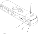
- Figure 9 llustrate the situation in figure 3C , after the lancet has been fired.
- Lock post 91 has now moved to the right, that is, to its position at the end closest to the actuator 60.
- the lock posts 91 no longer engage the actuator posts 66 and actuator 60 can be depressed.
- the arrangement illustrated has the actuator at the opposite end to the lancet.
- this is convenient for the user, as they lance their finger at one end, place the blood onto the blood recess 51, and operate the actuator from the other end.
- the interior structure is better organised that in arrangements in which the actuator, reservoir and lancet were all at the same end.
- a further advantageous feature is that the actuator brings the blood into contact with the test strip in a controlled way, in which the movement is controlled by the device and is not dependant upon the force used by the user.
- the actuator simply releases the blood collection unit, no understanding or other control is required by the user.
- test fluid and blood preferably each onto their respective contact areas on the strip, means that the user need not worry about sequencing or volume control, or even timing - the device performs these tasks from a single actuator operation.
- the reservoir unit is preferable formed and constructed as disclosed in more detail in PCT/AU2016/051134 . While this is a suitable implementation, the present invention is not limited to a fluid delivery mechanism constructed in this manner.
- Figures 10 and 11 illustrate respectively a full and a discharged fluid unit 105.
- the unit includes a reservoir 100, a well 101 with a discharge opening 102, and a conduit 104 connecting reservoir 100 to well 101.
- Conduit 104 is sealed by a frangible seal, which ruptures operatively under pressure from the actuator 60.
- the reservoir is forced to close and forces fluid into well 101 and then through opening 102, which is in contact with the test strip 80.
- the fluid unit 105 may be conveniently formed from laminated heat sealable material, with a relatively stronger seal around the periphery and overlapping edges 106, with the weaker, frangible seal 103, preferably formed as per the above referenced application.
- the size of the fluid unit, as well as the capacity of the blood collecting unit, may be varied by appropriate dimensioning to suit the requirements of the test. It will be apparent that within the size constraints of the device, a variety of size options can be accommodated, so that the same basic device may be varied in those component only to provide volumes suitable for different tests.
- the present invention may be implemented including electronic components, for example an automated reader for a lateral flow test, or an electronic test material.
- the actuator may additionally serve to activate the electronics, for example using a projection to operate a switch to close a circuit.
Landscapes
- Health & Medical Sciences (AREA)
- Life Sciences & Earth Sciences (AREA)
- Engineering & Computer Science (AREA)
- Biomedical Technology (AREA)
- Physics & Mathematics (AREA)
- Hematology (AREA)
- General Health & Medical Sciences (AREA)
- Molecular Biology (AREA)
- Biophysics (AREA)
- Pathology (AREA)
- Public Health (AREA)
- Animal Behavior & Ethology (AREA)
- Medical Informatics (AREA)
- Heart & Thoracic Surgery (AREA)
- Veterinary Medicine (AREA)
- Surgery (AREA)
- Chemical & Material Sciences (AREA)
- Analytical Chemistry (AREA)
- Food Science & Technology (AREA)
- Urology & Nephrology (AREA)
- Medicinal Chemistry (AREA)
- Biochemistry (AREA)
- General Physics & Mathematics (AREA)
- Immunology (AREA)
- Ecology (AREA)
- Optics & Photonics (AREA)
- Clinical Laboratory Science (AREA)
- Chemical Kinetics & Catalysis (AREA)
- Measurement Of The Respiration, Hearing Ability, Form, And Blood Characteristics Of Living Organisms (AREA)
- Investigating Or Analysing Biological Materials (AREA)
Description
- The present invention relates to devices for conducting blood tests using an integrated testing device.
- Blood tests have conventionally been conducted by drawing blood, for example by venepuncture, and submitting blood for testing to central pathology facilities. Increasingly, there is a demand for tests to be undertaken and interpreted at the point of care, and for self-tests where the user takes their own blood, submits it to a local test device and reads the test outcome.
- Advances in the structure, chemistry and biochemistry of test materials have produced the possibility to extend self- testing to a much wider group of users and conditions, particularly where the potential exists for relatively rapid tests. Tests have been developed to allow for testing for many indications, for example various pathogen, antibodies, blood components, biochemical markers, and other substances.
- The present applicant has filed applications directed at various aspects of integrated test units, including for example
WO/2012/048388 ,WO/2011/113114 , andWO2015075677 . -
WO 2012/048388 discloses an assembly for sampling bodily fluid. The assembly has a membrane penetration device that has a membrane penetrating element for penetrating a bodily membrane to release a bodily fluid. The assembly has also a collector that is configured in a collection position to take up the released bodily fluid and retain the fluid for delivery to a test element. -
WO 2011/113114 discloses a composite diagnostic system that includes a support member that has a membrane penetration element; a bodily collection point for collection of a bodily fluid released by application of the membrane penetration element to a user's body and a test material positioned in the support member such that in use the bodily fluid is brought into contact with the test material. -
WO 2015/075677 discloses an integrated testing device for testing bodily fluids. The device has a test component, a reservoir containing a test fluid and a control vessel. - Other examples of devices that determine the presence of an analyte in a fluid sample include
US 2007/0087357 ,US 2005/0186111 andUS 2008/0300508 . -
US 2007/0087357 discloses devices, methods and kits for conducting an assay to determine the presence or amount of an analyte in a fluid sample. The device has a sample application element and a flow path matrix that facilitates fluidic flow by capillary action. -
US 2005/0186111 discloses a self-contained device using a gravitationally encouraged, interrupted downward and programmed flow of fluid to provide rapid confirmatory immunological testing (RCIT) in a point-of-care setting. -
US 2008/0300508 discloses medical diagnostics devices and more specifically to a diagnostic patch attachable to a subject's skin for performing a rapid blood test. - There is a need for further refinement in such devices, for example in relation to facilitating self-testing. Self-testing presents a very specific set of design challenges, relative to tests intended for professional or regular users. The user will often not have regular, or even any, experience in conducting such tests. Thus, the risk that errors will be made, which in turn undermine the quality of the outcome, is significant.
- It is an object of the present invention to provide integrated testing devices which are reliable and reduce the risk of errors by the user.
- In first broad form, the present invention provides a device in which test fluid and blood are delivered to a test material by a single actuator.
- According to one aspect, the present invention provides an integrated blood test unit including a blood collection unit, a test component, a reservoir containing test fluid, and an actuator, wherein operatively activation of the actuator causes movement of the blood collection unit to deliver blood to the test component, and activation of the actuator further causes the test fluid to be released from the reservoir in order to allow the test fluid to contact the test component.
- Suitable implementations of the present invention accordingly allow for easily used devices, particularly for self test applications, which facilitate
- Illustrative embodiments of the present invention will now be described with reference to the accompanying drawings, in which:
-
Figure 1 shows an isometric view of one implementation of the present invention; -
Figure 2 is an exploded view of the components of the implementation offigure 1 ; -
Figure 3A to 3D are cross-sectional views of a device at various stages of operation; -
Figure 4 is a detailed isometric view of the blood collection unit; -
Figure 5 is a detailed cross sectional view illustrating the catch operation for the activation button; -
Figure 6 is a view of the blood collection unit from the opposite end tofigure 4 ; -
Figure 7 is a detailed cross-sectional view illustrating the pivot of the blood collection unit; -
Figure 8 is a view, partly in section, illustrating the operation of the interlock member before the lancet is actuated; -
Figure 9 is a view similar tofigure 8 , showing the interlock after lancet actuation; and -
Figures 10 and 11 illustrate a fluid unit, in a full and discharged condition. - The present invention will be described with reference to a particular implementation. It should be understood that the implementation discussed is purely illustrative, and is in no way limitative of the scope of the inventions disclosed. Various inventive features are disclosed, and it will be understood that this disclosure includes them in the combination as discussed, as well in in their individual integers and in subcombinations.
- It should be appreciated that the present invention in one form extends to a complete test device, including a test material, such as a test strip. The test material may be in any form and may be intended to be read by the user either directly, for example via conventional line indications, or using an automated or partly automated reading device. The examples described relate primarily to a conventional lateral flow test strip, however, the invention may be employed with alternative test materials, for example other strip based tests, or electronic sensors. The present invention is not limited to any particular test, condition, test approach or test reading process. Aspects of the present invention are concerned, rather, with various usability, mechanical and fluid handling aspects, not the biochemistry or other aspects of the test material as such.
- However, the present invention also extends to a device which does not include the test material, but is adapted to do so. Where the context admits, the description and claims should be read to include both a device with a test strip or other material in place, and a device in which the test strip or other material has not yet been inserted. Thus, the present invention extends to both devices with an integrated test material, and devices which have yet to have a test component inserted.
- The present invention contemplates that a test fluid is dispensed onto the test material. This may be a suitable buffer, or any other fluid which it is desirable or necessary to dispense onto the test material, in order to facilitate the test. It will be appreciated that the nature and volume of test fluid will be dependent upon the test to be performed, and it is anticipated that the nature of the test fluid and volume will be selected to complement the intended test and test material. In some cases the test fluid may be an active component of the test, and not merely a buffer or carrier.
-
Figure 1 illustrates adevice 10 according to one implementation of the present invention. It includes an upper shell 30,lower shell 20,blood collection unit 50 withblood collection recess 51 andchannel 52.Device 10 further includesactuator 60,lancet mechanism 40 withcap 41, andresult window 70. - The operation of the device, from perspective of the user, will now be described. This will be in the context of a self-test situation. However, it will be appreciated that many of the features and advantages of the illustrated device are also advantageous in point of care or other applications, and the scope of the invention includes self tests, professional use and point of care applications.
- First, a user washes their hands, ideally with warm water to increase blood flow, and massages the selected finger for 10 seconds. The user then removes the
lancet cap 41, by twisting and pulling. The user then presses hard on the exposedlancet mechanism 40. This releases a biased lancet which penetrates the user's finger, and then retracts within the housing ofmechanism 40. - The user then milks the finger, so as to produce droplet of blood. Typically, 5 to 20 µl are required. The user places their finger against the
blood collection recess 52, so that blood is collected. The blood flows into therecess 52. This provides a visual indication to the user that sufficient blood has been delivered to provide a valid test. - The next step is to depress
actuator 60. As will be explained in more detail, until the lancet has been operated, an interlock prevents the actuator from being depressed. Activating the actuator causes theblood collection unit 50 to pivot slightly downward, so that thechannel 52 contacts the test material 80 (not visible here) and the blood is delivered. At the same time,actuator 60 also depresses a reservoir of test fluid 100 (not visible here) and this is also delivered to thetest material 80. A latch mechanism hold the actuator in the engaged position, so that the fluid is delivered. - A further feature of
device 10 is theresult window 70. Conventionally, a window is provided in a test device to show two indicator lines, for test outcome and a control line to indicate that the test is valid. These are conventionally open. According to the present implementation, a solid, partly transparent cover is provided over the test and control indicators. This prevents the user inadvertently putting the blood sample into the wrong opening. After the period appropriate for the test, the test and control lines are visible through theresults window 70. - The structure and mechanism of
device 10 will be further understood by reference tofigure 2 .Lower shell 20 includes various lugs and location features, including anopening 21 for thelancet mechanism 40. Next is theinterlock 90, whose operation will be described below in more detail. -
Lancet mechanism 40 is conventional in operation, and any suitable lancet mechanism could be substituted as will be apparent to those skilled in the art.Lancet 42 is biased byspring 43, so that whenlancet housing 45 is sufficiently depressed relative todevice 10, tabs break away and thelancet 42 projects and then returnspring 47 retracts it for safety.Safety cap 44 is increased in usability by the addition ofsafety cover 41, formed ashalves - Next in the assembly is
strip carrier 85, on whichstrip 80 rests in use and is retained in the correct position for testing, usingretainer 86. - Next is
blood collection unit 50, includinglug 56 andspring 55, which allow for the positive operation of the pivot function when the actuator is released, as will be described below. -
Results window 70 as discussed above is transparent, so that the control and test lines can be seen. Preferably, the housing adjacent to the results window has markings of T and C adjacent to the potential results lines, indicating test and control. -
Actuator 10 also compressesplate 75, which in turn compresses test fluidtest fluid reservoir 100, not shown in this illustration, againstsurface 87. Upper shell 30 includesactuator 60, forms with alive hinge 61 to allow it to pivot downwards. -
Figures 3A, 3B, 3C and 3D illustrate the operation of the various components ofdevice 10, in cross section, at different points of operation ofdevice 10. It is important to understand that the device described is a single use device, intended for a single test. Once the device has passed a stage in operation, for example the lancet has been fired, then it is not possible to return to an earlier stage and re-use the lancet. - In
Figure 3A , the device is as supplied, ready for use. Thesafety cap 44 is in position andlancet 42 has not been operated.Blood collection unit 50 is positioned so that itslower edge 53 is not in contact with thetest strip 80.Reservoir 100 is filled with test fluid, for example buffer or any other fluid required to facilitate the test.Actuator 60 is not depressed. Theinterlock member 90 is located engaged with thelancet mechanism 40, and is slidable on thelower shell 20. At this stage, it is in the (in this view) left hand position, and the lock posts 91 are positioned to engage actuator posts 66 (not visible here, seefigure 9 ). Thus, the user is prevented from depressing the actuator, and so neither blood nor test fluid can be delivered totest strip 80. - As a result, the user has limited opportunities to make erroneous use of the device. The accompanying instructions next tell the user to remove the
safety cap 44. -
Figure 3B illustratesdevice 10 with thesafety cap 44 removed. The lancet is now ready for use. At this stage, nothing else in the device is altered. The user pressesfront surface 45 against the prepared finger, thelancet 42 fires, penetrates the finger, and retracts into thelancet mechanism 40. This is the situation shown infigure 3C . - The lancet mechanism is now in the retracted state, with
front surface 45 moved back intolower shell 20, and thelancet 42 safely stored. Additionally, the retraction has pushedinterlock member 90 to the right, and so moved lock posts 91 (only one is visible) to the right, so that they no longer prevent the movement ofactuator 60. - The user at this stage should produce a droplet of blood, and place it into contact with
blood collection recess 51. The user receives a visual indication that sufficient blood is provided whengroove 52 is filled.Device 10 is now ready for the actuator to be depressed. - It is important to understand the mechanism of the blood collection unit. It is as this stage captured in a locked, upward position, biased by
spring 55 onlug 56. It is also, viatransverse section 58, captured ingroove 36 oflatch 35. Thus, at this stage theblood collection unit 50 is held away from contact withtest strip 80. This can be seen in more detail infigure 5 . A more detailed view ofblood collection unit 50 can be seen infigure 4 . - The user next depresses
actuator 60. This has several consequences. Thereservoir 100 is located directly under the actuator, so as to be depressed and the test fluid discharged into well 101 for discharge via opening 102 ontotest strip 80. Thus, test fluid is discharged onto thetest strip 80. - The actuator moving down also releases
transverse section 58 fromgroove 36, andspring 55 then forces theblood collection unit 50 to pivot downwards, about pivot pins 53, 54.Figure 6 provides a more detailed view of theblood collection member 50 in which the pivot pins 53, 54 can be seen. These are located inholders 35 extending from top shell 30, one of which is visible in the detailed view offigure 7 . - As a result of the pivoting movement, the
lower edge 53 engages thetest strip 80, and blood flows by capillary action fromgroove 52 into the bibulous material of thetest strip 80. - The
actuator 60 is further locked into the closed position.Latch 35 viarecess 36 now engages thelower projection 64 ofactuator 60, so that it is retained in the closed position. The retention assists in producing positive pressure within thereservoir 100 and well 101, so that the fluid is forced fromreservoir 100 and into thetest strip 80, so as to minimise surface losses of the test fluid and provide reliable delivery to thetest strip 80. - The user then waits the appropriate time, and determines (in this case) if lines appear in the test and control windows. The test result can thereby be determined, together with verification that a valid test has been conducted.
- It is generally preferable that the blood is always delivered at the same time, or earlier, than the test fluid, particularly if the fluid is a buffer. The purpose of the buffer is to provide enough fluid to sufficiently drive the movement of the blood along the strip. If the buffer is added before the blood, or runs ahead of the blood, the test may not function correctly.
- In one respect, the test fluid is added at about
area 81 on the test strip, and blood is delivered fromblood collection unit 50, because the action ofspring 55, at aboutarea 82. Hence, even if the blood and buffer are added at the same time, the buffer is behind the blood. -
Figures 8 and9 illustrate the operation of theinterlock member 90 in more detail.Figure 8 corresponds to the situation infigure 3A , in whichdevice 10 is ready for use, but thelancet 42 has not been prepared or fired.Lock post 91 is at it's original, left-most position, that is, closest to the lancet end. It will be understood that another lock post is located on the other side of the lower shell, as can be seen infigure 2 . In this position, lockpost 91 engagesactuator post 66, so thatactuator 60 cannot be depressed. -
Figure 9 llustrate the situation infigure 3C , after the lancet has been fired.Lock post 91 has now moved to the right, that is, to its position at the end closest to theactuator 60. The lock posts 91 no longer engage the actuator posts 66 andactuator 60 can be depressed. - The arrangement illustrated has the actuator at the opposite end to the lancet. When the device is used for self test, this is convenient for the user, as they lance their finger at one end, place the blood onto the
blood recess 51, and operate the actuator from the other end. The interior structure is better organised that in arrangements in which the actuator, reservoir and lancet were all at the same end. - A further advantageous feature is that the actuator brings the blood into contact with the test strip in a controlled way, in which the movement is controlled by the device and is not dependant upon the force used by the user. The actuator simply releases the blood collection unit, no understanding or other control is required by the user.
- Similarly, the more or less simultaneous release of test fluid and blood, preferably each onto their respective contact areas on the strip, means that the user need not worry about sequencing or volume control, or even timing - the device performs these tasks from a single actuator operation.
- The reservoir unit is preferable formed and constructed as disclosed in more detail in
PCT/AU2016/051134 -
Figures 10 and 11 illustrate respectively a full and a dischargedfluid unit 105. The unit includes areservoir 100, a well 101 with adischarge opening 102, and aconduit 104 connectingreservoir 100 to well 101.Conduit 104 is sealed by a frangible seal, which ruptures operatively under pressure from theactuator 60. The reservoir is forced to close and forces fluid into well 101 and then throughopening 102, which is in contact with thetest strip 80. - The
fluid unit 105 may be conveniently formed from laminated heat sealable material, with a relatively stronger seal around the periphery and overlappingedges 106, with the weaker,frangible seal 103, preferably formed as per the above referenced application. - The size of the fluid unit, as well as the capacity of the blood collecting unit, may be varied by appropriate dimensioning to suit the requirements of the test. It will be apparent that within the size constraints of the device, a variety of size options can be accommodated, so that the same basic device may be varied in those component only to provide volumes suitable for different tests.
- The present invention may be implemented including electronic components, for example an automated reader for a lateral flow test, or an electronic test material. In such an implementation, the actuator may additionally serve to activate the electronics, for example using a projection to operate a switch to close a circuit.
Claims (12)
- An integrated blood test unit (10) including a blood collection unit (50), a test component (80), a reservoir (100) containing test fluid, and an actuator (60), wherein operatively activation of the actuator (60) causes movement of the blood collection unit (50) to deliver blood to the test component (80), and activation of the actuator (60) further causes the test fluid to be released from the reservoir (100) in order to allow the test fluid to contact the test component.
- An integrated blood test unit (10) according to claim 1, wherein in a sample collection position the blood collection unit (50) is biased towards the test component (80) but prevented from delivering the blood to the test component (80) by a latch (35), and wherein operatively, activation of the actuator (60) releases the latch (35) and allows the blood collection unit (50) to move to a sample delivery position, so that blood is delivered to the test component (80).
- An integrated blood test unit (10) according to claim 1 or claim 2, wherein in response to activation of the actuator (60), the blood collection unit (50) tilts into the sample delivery position so as to deliver the blood to the test component (80).
- An integrated blood test unit (10) according to any one of the preceding claims, wherein the test unit (10) further includes an electronic component, and the electronic component is made operative by activation of the actuator (60).
- An integrated blood test unit according to any one of the preceding claims, wherein a retainer (35) is provided, so that operatively, after the actuator (60) is activated, the actuator (60) is locked into an actuated position.
- An integrated blood test unit (10) according to claim 5, wherein the locked actuator (60) exerts a continuing force so as to compress the reservoir (100) in order to dispense the test fluid onto the test component (80).
- An integrated test unit (10) according to any one of the preceding claims, wherein the test unit (10) further provides an integrated lancet (42), and an interlock is provided so that in operation, the actuator (60) is inoperative, and so the blood collection unit (50) cannot move to a delivery position, and the test fluid cannot be released, until after the lancet (42) has been discharged.
- An integrated blood test unit (10) according to any one of the preceding claims, wherein the test unit (10) further includes a transparent window (70) located so that the or each visual indication by the test component (80) is visible.
- An integrated blood test unit (10) according to any one of the preceding claims, further including an integrated lancet (42), wherein the actuator (60) and the integrated lancet (42) are located at opposite ends on the integrated test unit, so that the operation of the lancet (42) is convenient for a self test relative to the actuator(60).
- An integrated blood test unit (10) according to any one of the preceding claims, wherein the blood collection unit (50) includes a blood collection recess (51), the recess (51) being adapted to directly receive blood from a user, the recess (51) including a channel (52) which operatively is adapted to progressively fills with blood, such that when the channel (52) is full it provides a visual indication to the user that sufficient blood has been received to conduct a test
- An integrated blood test unit (10) according to claim 10, wherein in operation the blood collection unit (50) is adapted to tilt downward to place an end of the channel (52) adjacent to the test component (80), so that blood flows from the channel (52) to the test component (80) .
- An integrated blood test unit (10) according to claim 11, wherein the unit is arranged so that in operation the blood is delivered to the test component (80) at an area (82), and the test fluid is delivered to the test component (80) at a second area (81), so that the test fluid is delivered behind the blood to test component (80) so that the test fluid can drive the movement of blood for use in the test component (80).
Applications Claiming Priority (2)
| Application Number | Priority Date | Filing Date | Title |
|---|---|---|---|
| AU2017904127A AU2017904127A0 (en) | 2017-10-12 | Integrated blood test device | |
| PCT/AU2018/051114 WO2019071323A1 (en) | 2017-10-12 | 2018-10-12 | Integrated blood test device |
Publications (4)
| Publication Number | Publication Date |
|---|---|
| EP3713489A1 EP3713489A1 (en) | 2020-09-30 |
| EP3713489A4 EP3713489A4 (en) | 2022-05-18 |
| EP3713489B1 true EP3713489B1 (en) | 2024-04-03 |
| EP3713489C0 EP3713489C0 (en) | 2024-04-03 |
Family
ID=66100158
Family Applications (1)
| Application Number | Title | Priority Date | Filing Date |
|---|---|---|---|
| EP18865881.9A Active EP3713489B1 (en) | 2017-10-12 | 2018-10-12 | Integrated blood test device |
Country Status (9)
| Country | Link |
|---|---|
| US (1) | US20210186390A1 (en) |
| EP (1) | EP3713489B1 (en) |
| JP (1) | JP2020536716A (en) |
| CN (1) | CN111372518B (en) |
| AU (1) | AU2018348794B2 (en) |
| BR (1) | BR112020007269A2 (en) |
| EA (1) | EA202090709A1 (en) |
| MX (1) | MX2020005685A (en) |
| WO (1) | WO2019071323A1 (en) |
Families Citing this family (6)
| Publication number | Priority date | Publication date | Assignee | Title |
|---|---|---|---|---|
| US12127838B2 (en) * | 2020-04-22 | 2024-10-29 | Willow Laboratories, Inc. | Self-contained minimal action invasive blood constituent system |
| IT202000009154A1 (en) | 2020-04-27 | 2021-10-27 | Zenares S R L | DISPOSABLE SELF-TEST DEVICE WITH SELF-CERTIFICATION CAPABILITY AND KIT CONTAINING THE SAME |
| CN111458492A (en) * | 2020-05-08 | 2020-07-28 | 山西医科大学 | POCT blood detection box |
| GB2594976A (en) | 2020-05-14 | 2021-11-17 | Owen Mumford Ltd | Test device |
| CN114778529B (en) * | 2022-02-28 | 2025-08-08 | 南京晶捷生物科技有限公司 | Integrated kit detection device and detection method thereof |
| WO2025231001A1 (en) * | 2024-04-30 | 2025-11-06 | Global Diagnostic Systems, Benefit LLC | Diagnostic devices and associated methods and kits |
Family Cites Families (17)
| Publication number | Priority date | Publication date | Assignee | Title |
|---|---|---|---|---|
| US4627445A (en) * | 1985-04-08 | 1986-12-09 | Garid, Inc. | Glucose medical monitoring system |
| US6368563B1 (en) * | 1999-03-12 | 2002-04-09 | Integ, Inc. | Collection well for body fluid tester |
| US20020188223A1 (en) * | 2001-06-08 | 2002-12-12 | Edward Perez | Devices and methods for the expression of bodily fluids from an incision |
| US20030212344A1 (en) * | 2002-05-09 | 2003-11-13 | Vadim Yuzhakov | Physiological sample collection devices and methods of using the same |
| WO2004084727A1 (en) * | 2003-03-27 | 2004-10-07 | Terumo Kabushiki Kaisha | Humor sampling implement and method of humor sampling |
| WO2005046437A2 (en) * | 2003-11-05 | 2005-05-26 | Separation Technology, Inc. | Disposable fluid sample collection device |
| US7638093B2 (en) | 2004-01-28 | 2009-12-29 | Dnt Scientific Research, Llc | Interrupted flow rapid confirmatory immunological testing device and method |
| US20090326355A1 (en) * | 2005-08-12 | 2009-12-31 | Brenneman Allen J | Integrated Test System for Monitoring Bodily Fluids |
| US7816122B2 (en) | 2005-10-18 | 2010-10-19 | Idexx Laboratories, Inc. | Lateral flow device with onboard reagents |
| US8741230B2 (en) * | 2006-03-24 | 2014-06-03 | Theranos, Inc. | Systems and methods of sample processing and fluid control in a fluidic system |
| US20080300508A1 (en) | 2007-05-30 | 2008-12-04 | Inverness Medical Switzerland Gmbh | Diagnostic patch |
| WO2009081405A2 (en) * | 2007-12-25 | 2009-07-02 | Rapidx Ltd. | Devices and methods for reduced-pain blood sampling |
| HUE026294T2 (en) * | 2010-03-19 | 2016-05-30 | Atomo Diagnostics Pty Ltd | Diagnostic system |
| AU2011316495B2 (en) * | 2010-10-15 | 2014-06-12 | Atomo Diagnostics Limited | Sampling assembly |
| US10180421B2 (en) * | 2012-03-30 | 2019-01-15 | Boston Microfluidics | Methods and systems to collect a biological sample |
| CN103149363A (en) * | 2013-03-06 | 2013-06-12 | 江苏岱洛医疗科技有限公司 | Integrated glucose meter |
| WO2015075677A1 (en) | 2013-11-21 | 2015-05-28 | Atomo Diagnostics Pty Limited | Fluid control in integrated testing devices |
-
2018
- 2018-10-12 BR BR112020007269-9A patent/BR112020007269A2/en not_active Application Discontinuation
- 2018-10-12 EA EA202090709A patent/EA202090709A1/en unknown
- 2018-10-12 EP EP18865881.9A patent/EP3713489B1/en active Active
- 2018-10-12 MX MX2020005685A patent/MX2020005685A/en unknown
- 2018-10-12 WO PCT/AU2018/051114 patent/WO2019071323A1/en not_active Ceased
- 2018-10-12 AU AU2018348794A patent/AU2018348794B2/en active Active
- 2018-10-12 JP JP2020541833A patent/JP2020536716A/en active Pending
- 2018-10-12 US US16/755,541 patent/US20210186390A1/en active Pending
- 2018-10-12 CN CN201880074553.8A patent/CN111372518B/en active Active
Also Published As
| Publication number | Publication date |
|---|---|
| BR112020007269A2 (en) | 2020-10-27 |
| CN111372518B (en) | 2024-01-19 |
| AU2018348794B2 (en) | 2023-12-21 |
| EP3713489A4 (en) | 2022-05-18 |
| JP2020536716A (en) | 2020-12-17 |
| AU2018348794A1 (en) | 2020-05-14 |
| CN111372518A (en) | 2020-07-03 |
| EA202090709A1 (en) | 2020-09-29 |
| WO2019071323A1 (en) | 2019-04-18 |
| EP3713489A1 (en) | 2020-09-30 |
| MX2020005685A (en) | 2020-08-20 |
| US20210186390A1 (en) | 2021-06-24 |
| EP3713489C0 (en) | 2024-04-03 |
Similar Documents
| Publication | Publication Date | Title |
|---|---|---|
| AU2018348794B2 (en) | Integrated blood test device | |
| US12082931B2 (en) | Blood sampling transfer device | |
| AU2023274147B2 (en) | Delivering and/or receiving fluids | |
| US10525463B2 (en) | Integrated testing device | |
| EP2986223B1 (en) | Blood sampling transfer device | |
| EP2986222B1 (en) | Biological fluid sampling transfer device and biological fluid separation and testing system | |
| US20220071534A9 (en) | Delivering and/or receiving fluids | |
| CA2751407A1 (en) | Test device for liquids of the human or animal body | |
| EA042596B1 (en) | COMPLETE BLOOD TEST DEVICE |
Legal Events
| Date | Code | Title | Description |
|---|---|---|---|
| STAA | Information on the status of an ep patent application or granted ep patent |
Free format text: STATUS: THE INTERNATIONAL PUBLICATION HAS BEEN MADE |
|
| PUAI | Public reference made under article 153(3) epc to a published international application that has entered the european phase |
Free format text: ORIGINAL CODE: 0009012 |
|
| STAA | Information on the status of an ep patent application or granted ep patent |
Free format text: STATUS: REQUEST FOR EXAMINATION WAS MADE |
|
| 17P | Request for examination filed |
Effective date: 20200806 |
|
| AK | Designated contracting states |
Kind code of ref document: A1 Designated state(s): AL AT BE BG CH CY CZ DE DK EE ES FI FR GB GR HR HU IE IS IT LI LT LU LV MC MK MT NL NO PL PT RO RS SE SI SK SM TR |
|
| AX | Request for extension of the european patent |
Extension state: BA ME |
|
| DAV | Request for validation of the european patent (deleted) | ||
| DAX | Request for extension of the european patent (deleted) | ||
| RAP3 | Party data changed (applicant data changed or rights of an application transferred) |
Owner name: ATOMO DIAGNOSTICS LIMITED |
|
| A4 | Supplementary search report drawn up and despatched |
Effective date: 20220421 |
|
| RIC1 | Information provided on ipc code assigned before grant |
Ipc: A61B 5/15 20060101ALI20220413BHEP Ipc: A61B 5/151 20060101ALI20220413BHEP Ipc: A61B 5/157 20060101AFI20220413BHEP |
|
| GRAP | Despatch of communication of intention to grant a patent |
Free format text: ORIGINAL CODE: EPIDOSNIGR1 |
|
| STAA | Information on the status of an ep patent application or granted ep patent |
Free format text: STATUS: GRANT OF PATENT IS INTENDED |
|
| INTG | Intention to grant announced |
Effective date: 20231107 |
|
| RIN1 | Information on inventor provided before grant (corrected) |
Inventor name: DAWSON, BENJAMIN Inventor name: VAN DE SANDE, BARBARA Inventor name: CUSACK, DOUG Inventor name: GIJZEL, MARTIJN Inventor name: SUTTON, DAVID Inventor name: POSTLE, WILL |
|
| GRAS | Grant fee paid |
Free format text: ORIGINAL CODE: EPIDOSNIGR3 |
|
| GRAA | (expected) grant |
Free format text: ORIGINAL CODE: 0009210 |
|
| STAA | Information on the status of an ep patent application or granted ep patent |
Free format text: STATUS: THE PATENT HAS BEEN GRANTED |
|
| AK | Designated contracting states |
Kind code of ref document: B1 Designated state(s): AL AT BE BG CH CY CZ DE DK EE ES FI FR GB GR HR HU IE IS IT LI LT LU LV MC MK MT NL NO PL PT RO RS SE SI SK SM TR |
|
| REG | Reference to a national code |
Ref country code: GB Ref legal event code: FG4D |
|
| REG | Reference to a national code |
Ref country code: CH Ref legal event code: EP |
|
| REG | Reference to a national code |
Ref country code: IE Ref legal event code: FG4D |
|
| REG | Reference to a national code |
Ref country code: DE Ref legal event code: R096 Ref document number: 602018067651 Country of ref document: DE |
|
| U01 | Request for unitary effect filed |
Effective date: 20240501 |
|
| U07 | Unitary effect registered |
Designated state(s): AT BE BG DE DK EE FI FR IT LT LU LV MT NL PT SE SI Effective date: 20240510 |
|
| PG25 | Lapsed in a contracting state [announced via postgrant information from national office to epo] |
Ref country code: IS Free format text: LAPSE BECAUSE OF FAILURE TO SUBMIT A TRANSLATION OF THE DESCRIPTION OR TO PAY THE FEE WITHIN THE PRESCRIBED TIME-LIMIT Effective date: 20240803 |
|
| PG25 | Lapsed in a contracting state [announced via postgrant information from national office to epo] |
Ref country code: HR Free format text: LAPSE BECAUSE OF FAILURE TO SUBMIT A TRANSLATION OF THE DESCRIPTION OR TO PAY THE FEE WITHIN THE PRESCRIBED TIME-LIMIT Effective date: 20240403 |
|
| PG25 | Lapsed in a contracting state [announced via postgrant information from national office to epo] |
Ref country code: GR Free format text: LAPSE BECAUSE OF FAILURE TO SUBMIT A TRANSLATION OF THE DESCRIPTION OR TO PAY THE FEE WITHIN THE PRESCRIBED TIME-LIMIT Effective date: 20240704 |
|
| PG25 | Lapsed in a contracting state [announced via postgrant information from national office to epo] |
Ref country code: ES Free format text: LAPSE BECAUSE OF FAILURE TO SUBMIT A TRANSLATION OF THE DESCRIPTION OR TO PAY THE FEE WITHIN THE PRESCRIBED TIME-LIMIT Effective date: 20240403 |
|
| PG25 | Lapsed in a contracting state [announced via postgrant information from national office to epo] |
Ref country code: CZ Free format text: LAPSE BECAUSE OF FAILURE TO SUBMIT A TRANSLATION OF THE DESCRIPTION OR TO PAY THE FEE WITHIN THE PRESCRIBED TIME-LIMIT Effective date: 20240403 |
|
| PG25 | Lapsed in a contracting state [announced via postgrant information from national office to epo] |
Ref country code: PL Free format text: LAPSE BECAUSE OF FAILURE TO SUBMIT A TRANSLATION OF THE DESCRIPTION OR TO PAY THE FEE WITHIN THE PRESCRIBED TIME-LIMIT Effective date: 20240403 |
|
| PG25 | Lapsed in a contracting state [announced via postgrant information from national office to epo] |
Ref country code: PL Free format text: LAPSE BECAUSE OF FAILURE TO SUBMIT A TRANSLATION OF THE DESCRIPTION OR TO PAY THE FEE WITHIN THE PRESCRIBED TIME-LIMIT Effective date: 20240403 Ref country code: NO Free format text: LAPSE BECAUSE OF FAILURE TO SUBMIT A TRANSLATION OF THE DESCRIPTION OR TO PAY THE FEE WITHIN THE PRESCRIBED TIME-LIMIT Effective date: 20240703 Ref country code: IS Free format text: LAPSE BECAUSE OF FAILURE TO SUBMIT A TRANSLATION OF THE DESCRIPTION OR TO PAY THE FEE WITHIN THE PRESCRIBED TIME-LIMIT Effective date: 20240803 Ref country code: HR Free format text: LAPSE BECAUSE OF FAILURE TO SUBMIT A TRANSLATION OF THE DESCRIPTION OR TO PAY THE FEE WITHIN THE PRESCRIBED TIME-LIMIT Effective date: 20240403 Ref country code: GR Free format text: LAPSE BECAUSE OF FAILURE TO SUBMIT A TRANSLATION OF THE DESCRIPTION OR TO PAY THE FEE WITHIN THE PRESCRIBED TIME-LIMIT Effective date: 20240704 Ref country code: ES Free format text: LAPSE BECAUSE OF FAILURE TO SUBMIT A TRANSLATION OF THE DESCRIPTION OR TO PAY THE FEE WITHIN THE PRESCRIBED TIME-LIMIT Effective date: 20240403 Ref country code: CZ Free format text: LAPSE BECAUSE OF FAILURE TO SUBMIT A TRANSLATION OF THE DESCRIPTION OR TO PAY THE FEE WITHIN THE PRESCRIBED TIME-LIMIT Effective date: 20240403 Ref country code: RS Free format text: LAPSE BECAUSE OF FAILURE TO SUBMIT A TRANSLATION OF THE DESCRIPTION OR TO PAY THE FEE WITHIN THE PRESCRIBED TIME-LIMIT Effective date: 20240703 |
|
| U20 | Renewal fee for the european patent with unitary effect paid |
Year of fee payment: 7 Effective date: 20241010 |
|
| REG | Reference to a national code |
Ref country code: DE Ref legal event code: R097 Ref document number: 602018067651 Country of ref document: DE |
|
| PG25 | Lapsed in a contracting state [announced via postgrant information from national office to epo] |
Ref country code: RO Free format text: LAPSE BECAUSE OF FAILURE TO SUBMIT A TRANSLATION OF THE DESCRIPTION OR TO PAY THE FEE WITHIN THE PRESCRIBED TIME-LIMIT Effective date: 20240403 Ref country code: SK Free format text: LAPSE BECAUSE OF FAILURE TO SUBMIT A TRANSLATION OF THE DESCRIPTION OR TO PAY THE FEE WITHIN THE PRESCRIBED TIME-LIMIT Effective date: 20240403 |
|
| PG25 | Lapsed in a contracting state [announced via postgrant information from national office to epo] |
Ref country code: SM Free format text: LAPSE BECAUSE OF FAILURE TO SUBMIT A TRANSLATION OF THE DESCRIPTION OR TO PAY THE FEE WITHIN THE PRESCRIBED TIME-LIMIT Effective date: 20240403 |
|
| PG25 | Lapsed in a contracting state [announced via postgrant information from national office to epo] |
Ref country code: SM Free format text: LAPSE BECAUSE OF FAILURE TO SUBMIT A TRANSLATION OF THE DESCRIPTION OR TO PAY THE FEE WITHIN THE PRESCRIBED TIME-LIMIT Effective date: 20240403 Ref country code: SK Free format text: LAPSE BECAUSE OF FAILURE TO SUBMIT A TRANSLATION OF THE DESCRIPTION OR TO PAY THE FEE WITHIN THE PRESCRIBED TIME-LIMIT Effective date: 20240403 Ref country code: RO Free format text: LAPSE BECAUSE OF FAILURE TO SUBMIT A TRANSLATION OF THE DESCRIPTION OR TO PAY THE FEE WITHIN THE PRESCRIBED TIME-LIMIT Effective date: 20240403 |
|
| PLBE | No opposition filed within time limit |
Free format text: ORIGINAL CODE: 0009261 |
|
| STAA | Information on the status of an ep patent application or granted ep patent |
Free format text: STATUS: NO OPPOSITION FILED WITHIN TIME LIMIT |
|
| 26N | No opposition filed |
Effective date: 20250106 |
|
| REG | Reference to a national code |
Ref country code: CH Ref legal event code: PL |
|
| PG25 | Lapsed in a contracting state [announced via postgrant information from national office to epo] |
Ref country code: MC Free format text: LAPSE BECAUSE OF FAILURE TO SUBMIT A TRANSLATION OF THE DESCRIPTION OR TO PAY THE FEE WITHIN THE PRESCRIBED TIME-LIMIT Effective date: 20240403 |
|
| PG25 | Lapsed in a contracting state [announced via postgrant information from national office to epo] |
Ref country code: CH Free format text: LAPSE BECAUSE OF NON-PAYMENT OF DUE FEES Effective date: 20241031 |
|
| PG25 | Lapsed in a contracting state [announced via postgrant information from national office to epo] |
Ref country code: IE Free format text: LAPSE BECAUSE OF NON-PAYMENT OF DUE FEES Effective date: 20241012 |
|
| U20 | Renewal fee for the european patent with unitary effect paid |
Year of fee payment: 8 Effective date: 20251014 |
|
| PGFP | Annual fee paid to national office [announced via postgrant information from national office to epo] |
Ref country code: GB Payment date: 20251014 Year of fee payment: 8 |
|
| PG25 | Lapsed in a contracting state [announced via postgrant information from national office to epo] |
Ref country code: CY Free format text: LAPSE BECAUSE OF FAILURE TO SUBMIT A TRANSLATION OF THE DESCRIPTION OR TO PAY THE FEE WITHIN THE PRESCRIBED TIME-LIMIT; INVALID AB INITIO Effective date: 20181012 |
|
| PG25 | Lapsed in a contracting state [announced via postgrant information from national office to epo] |
Ref country code: HU Free format text: LAPSE BECAUSE OF FAILURE TO SUBMIT A TRANSLATION OF THE DESCRIPTION OR TO PAY THE FEE WITHIN THE PRESCRIBED TIME-LIMIT; INVALID AB INITIO Effective date: 20181012 |