EP3713205A1 - Reading device and image forming apparatus - Google Patents
Reading device and image forming apparatus Download PDFInfo
- Publication number
- EP3713205A1 EP3713205A1 EP18879709.6A EP18879709A EP3713205A1 EP 3713205 A1 EP3713205 A1 EP 3713205A1 EP 18879709 A EP18879709 A EP 18879709A EP 3713205 A1 EP3713205 A1 EP 3713205A1
- Authority
- EP
- European Patent Office
- Prior art keywords
- section
- casing
- linking member
- cover
- cover section
- Prior art date
- Legal status (The legal status is an assumption and is not a legal conclusion. Google has not performed a legal analysis and makes no representation as to the accuracy of the status listed.)
- Granted
Links
Images


Classifications
-
- H—ELECTRICITY
- H04—ELECTRIC COMMUNICATION TECHNIQUE
- H04N—PICTORIAL COMMUNICATION, e.g. TELEVISION
- H04N1/00—Scanning, transmission or reproduction of documents or the like, e.g. facsimile transmission; Details thereof
- H04N1/00519—Constructional details not otherwise provided for, e.g. housings, covers
- H04N1/00551—Top covers or the like
- H04N1/00554—Latches or hinges therefor
-
- G—PHYSICS
- G03—PHOTOGRAPHY; CINEMATOGRAPHY; ANALOGOUS TECHNIQUES USING WAVES OTHER THAN OPTICAL WAVES; ELECTROGRAPHY; HOLOGRAPHY
- G03B—APPARATUS OR ARRANGEMENTS FOR TAKING PHOTOGRAPHS OR FOR PROJECTING OR VIEWING THEM; APPARATUS OR ARRANGEMENTS EMPLOYING ANALOGOUS TECHNIQUES USING WAVES OTHER THAN OPTICAL WAVES; ACCESSORIES THEREFOR
- G03B27/00—Photographic printing apparatus
- G03B27/32—Projection printing apparatus, e.g. enlarger, copying camera
- G03B27/52—Details
- G03B27/62—Holders for the original
-
- G—PHYSICS
- G03—PHOTOGRAPHY; CINEMATOGRAPHY; ANALOGOUS TECHNIQUES USING WAVES OTHER THAN OPTICAL WAVES; ELECTROGRAPHY; HOLOGRAPHY
- G03G—ELECTROGRAPHY; ELECTROPHOTOGRAPHY; MAGNETOGRAPHY
- G03G21/00—Arrangements not provided for by groups G03G13/00 - G03G19/00, e.g. cleaning, elimination of residual charge
- G03G21/16—Mechanical means for facilitating the maintenance of the apparatus, e.g. modular arrangements
- G03G21/1604—Arrangement or disposition of the entire apparatus
-
- H—ELECTRICITY
- H04—ELECTRIC COMMUNICATION TECHNIQUE
- H04N—PICTORIAL COMMUNICATION, e.g. TELEVISION
- H04N1/00—Scanning, transmission or reproduction of documents or the like, e.g. facsimile transmission; Details thereof
- H04N1/00519—Constructional details not otherwise provided for, e.g. housings, covers
- H04N1/00557—Connection or assembly of components or elements
-
- H—ELECTRICITY
- H04—ELECTRIC COMMUNICATION TECHNIQUE
- H04N—PICTORIAL COMMUNICATION, e.g. TELEVISION
- H04N1/00—Scanning, transmission or reproduction of documents or the like, e.g. facsimile transmission; Details thereof
- H04N1/04—Scanning arrangements, i.e. arrangements for the displacement of active reading or reproducing elements relative to the original or reproducing medium, or vice versa
- H04N1/10—Scanning arrangements, i.e. arrangements for the displacement of active reading or reproducing elements relative to the original or reproducing medium, or vice versa using flat picture-bearing surfaces
-
- H—ELECTRICITY
- H04—ELECTRIC COMMUNICATION TECHNIQUE
- H04N—PICTORIAL COMMUNICATION, e.g. TELEVISION
- H04N2201/00—Indexing scheme relating to scanning, transmission or reproduction of documents or the like, and to details thereof
- H04N2201/0077—Types of the still picture apparatus
- H04N2201/0094—Multifunctional device, i.e. a device capable of all of reading, reproducing, copying, facsimile transception, file transception
Definitions
- the present invention is related to a reading device and an image forming apparatus.
- An image forming apparatus described in Patent Literature 1 includes an open and close section, a main body section, a flexible flat cable, and a guide section.
- the open and close section is linked to the main body section so as to be able to ascend and descend and to rotate.
- the open and close section is linked to the main body section by means of a hinge section.
- the flexible flat cable electrically connects a reading section and a control substrate to each other.
- the guide section guides the flexible flat cable so that the flexible flat cable follows the rotation or the ascent and descent of the open and close section.
- Patent Literature 1 Japanese Patent Application Laid-Open Publication No. 2011-205341
- the hinge section may come out of a guide hole formed in the main body section, and the open and close section (a cover section) may be detached from the main body section (a casing). Further, when the open and close section is detached from the main body section, the flexible flat cable may be detached from either or both the reading section and the control substrate.
- the reading device includes: a reading section, a casing, a cover section, a conveyance section, an interposed member, a controller, a cable, and a linking member.
- the reading section reads an image formed on a sheet.
- the casing houses the reading section therein. It is possible to place the cover section on the casing.
- the conveyance section is housed in the cover section and conveys the sheet.
- the interposed member is interposed between the cover section and the casing.
- the controller is housed in the casing and controls the conveyance section.
- the cable is connected to the controller, is also connected to the conveyance section, and transfers a control signal output by the controller to the conveyance section.
- the linking member is linked to the cover section and is also linked to the casing.
- the casing has a casing bore located therein for placement of the interposed member.
- the interposed member includes a first member and a second member.
- the first member is inserted in the casing bore and supported so as to be movable in a vertical direction.
- the second member is rotatably attached to the first member.
- the cover section is fixed to the second member.
- an image forming apparatus includes the reading device and an image forming section.
- the image forming section forms an image on a sheet.
- the controller further controls the image forming section.
- the casing further houses the image forming section therein.
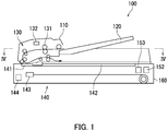
- FIG. 1 is a schematic cross-sectional view of the reading device 100.
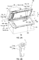
- FIG. 2A is a perspective view of the reading device 100.
- the reading device 100 includes a cover section 110, a tray 120, and a conveyance section 130.
- the cover section 110 has a hollow shape.
- the tray 120 is disposed on the outside of the cover section 110.
- the tray 120 is linked to the cover section 110.
- the tray 120 has one or more sheets loaded thereon.
- Each of the sheets may be, for example, sheets of plain paper, copy paper, recycled paper, thin paper, thick paper, glossy paper, or overhead projector (OHP) film.
- the cover section 110 is rotatably supported. More specifically, the cover section 110 is supported so as to be rotatable about a rotation axis L.
- the rotation axis L is the rotation axis of the cover section 110.
- the cover section 110 includes a rotation edge section 111 and a fulcrum edge section 112.
- the rotation edge section 111 is such an edge section of the cover section 110 that is positioned on a second side in terms of a first direction D1 while the cover section 110 is closed.
- the fulcrum edge section 112 is such an edge section of the cover section 110 that is positioned on a first side in terms of the first direction D1 while the cover section 110 is closed.
- the fulcrum edge section 112 is disposed along the rotation axis L.
- the rotation edge section 111 rotates about the fulcrum edge section 112 as a center.
- the rotation edge section 111 and the fulcrum edge section 112 each extend in a second direction D2.
- the second direction D2 is a direction parallel to the rotation axis L of the cover section 110.
- the first direction D1 is a direction perpendicular to the second direction D2.
- the first direction D1 and the second direction D2 are each a direction parallel to the horizontal direction.
- the conveyance section 130 conveys the sheet. More specifically, the conveyance section 130 conveys the sheet from the tray 120.
- the conveyance section 130 functions as an auto document feeder (ADF).
- ADF auto document feeder
- the conveyance section 130 is housed in the cover section 110.
- the conveyance section 130 includes rollers 131 and a first driving section 132.
- the rollers 131 include, for example, pickup rollers, separation rollers, conveyance rollers, and ejecting rollers.
- the pickup rollers forward the sheet loaded on the tray 120 to the inside of the cover section 110.
- the separation rollers forward the sheet while separating the sheet from one another.
- the conveyance rollers convey the sheet on the inside of the cover section 110.
- the ejecting rollers eject the sheet conveyed by the conveyance rollers, to the outside of the cover section 110.
- the first driving section 132 is a driving source that rotates the rollers 131.
- the first driving section 132 rotates the rollers 131 so that the rollers 131 convey the sheet. More specifically, each of the pairs of rollers 131 conveys the sheet by rotating while having the sheet held therebetween.
- the first driving section 132 may be a motor, for example.
- the reading device 100 further includes an image reading section 140.
- the image reading section 140 includes an opposing section 141, a loading section 142, a reading section 143, and a second driving section 144.
- the opposing section 141 is arranged in a location so as to be able to oppose the sheet conveyed by the conveyance section 130.
- the opposing section 141 is arranged on a conveyance path of the sheet conveyed by the conveyance section 130.
- the opposing section 141 may be a layer of contact glass, for example. It is possible to load any sheet on the loading section 142.
- the loading section 142 is arranged on the second side in terms of the second direction D2 with respect to the opposing section 141.
- the loading section 142 may be a layer of contact glass, for example.
- the reading section 143 reads an image formed on any sheet. More specifically, the reading section 143 reads an image formed on each of the sheets conveyed by the conveyance section 130. While the cover section 110 is closed, the reading section 143 reads the image formed on a sheet conveyed by the conveyance section 130. Also, the reading section 143 reads an image formed on a sheet loaded on the loading section 142. "Reading an image” denotes obtaining image data representing the image by scanning the image.
- the reading section 143 may be a contact image sensor (CIS).
- the reading section 143 includes a light emitting section such as a light emitting diode (LED) and an imaging section such as an image sensor. The reading section 143 scans the image formed on the sheet by employing the light emitting section and the imaging section.
- a light emitting section such as a light emitting diode (LED)
- an imaging section such as an image sensor. The reading section 143 scans the image formed on the sheet by employing the light emitting section and the imaging section.
- the reading section 143 is arranged below the opposing section 141. Further, the reading section 143 is arranged below the loading section 142. The reading section 143 is supported so as to be movable in the second direction D2.
- the reading section 143 reads the image formed on the sheet.
- the reading section 143 reads the image formed on the sheet.
- the reading section 143 reads the image formed on the sheet.
- the reading section 143 reads the image formed on the sheet.
- the second driving section 144 is a driving source that moves the reading section 143.
- the second driving section 144 may be a motor, for example.
- the reading device 100 further includes an input section 151, storage 152, and a controller 153.
- the input section 151 receives an instruction input to the reading device 100. Via the input section 151, for example, an instruction indicating that the image formed on the sheet should be read is input.
- the input section 151 includes, for example, either or both a touch panel and a group of operation keys.
- the storage 152 includes a storage device.
- the storage device includes a main storage device (e.g., semiconductor memory) such as read only memory (ROM) and random access memory (RAM) and may further include an auxiliary storage device (e.g., a hard disk drive). Either or both the main storage device and the auxiliary storage device store therein various types of computer programs to be executed by the controller 153.
- main storage device e.g., semiconductor memory
- ROM read only memory
- RAM random access memory
- auxiliary storage device e.g., a hard disk drive
- the controller 153 includes a processor such as a central processing unit (CPU) and a micro processing unit (MPU).
- the controller 153 controls each element of the reading device 100. More specifically, by executing the computer programs stored in one or more storage devices, the processor of the controller 153 controls the conveyance section 130 and the reading section 143. Even more specifically, in the first embodiment, the controller 153 controls the first driving section 132, the reading section 143, and the second driving section 144.
- the controller 153 controls the first driving section 132 so that the first driving section 132 rotates the rollers 131 to convey the sheet. Further, the controller 153 controls the reading section 143 so that the reading section 143 reads the image formed on the sheet. Further, the controller 153 controls the second driving section 144 so that the second driving section 144 moves the reading section 143.
- the reading device 100 further includes a casing 160.
- the casing 160 has a hollow shape.
- the casing 160 houses therein the image reading section 140, the storage 152, and the controller 153.
- the casing 160 includes a ceiling section 161, a first opening section 162, and a second opening section 163.
- the ceiling section 161 is a plate-like member.
- the ceiling section 161 is arranged in a top section of the casing 160.
- the ceiling section 161, the opposing section 141, and the loading section 142 close the top section of the casing 160.
- the first opening section 162 and the second opening section 163 are arranged in the top section of the casing 160.
- the first opening section 162 and the second opening section 163 are formed in the ceiling section 161.
- the first opening section 162 and the second opening section 163 allow communication between the outside of the casing 160 and the inside of the casing 160.
- the first opening section 162 and the second opening section 163 are spaced apart from each other in the second direction D2.
- the first opening section 162 is arranged with the opposing section 141.
- the first opening section 162 is closed by the opposing section 141.
- the second opening section 163 is arranged with the loading section 142.
- the second opening section 163 is closed by the loading section 142.
- the casing 160 further includes a pair of casing bores 164 and a through hole 165.
- Each of the paired casing bores 164 and the through hole 165 is formed in the top section of the casing 160.
- Each of the paired casing bores 164 and the through hole 165 is formed in the ceiling section 161.
- the paired casing bores 164 and the through hole 165 allow communication between the outside of the casing 160 and the inside of the casing 160.
- Each of the paired casing bores 164 and the through hole 165 extends in the vertical direction V.
- the paired casing bores 164 and the through hole 165 are arranged in the edge section of the casing 160 positioned on the first side in terms of the first direction D1.
- the paired casing bores 164 and the through hole 165 are spaced apart from each other in the second direction D2. Further, the through hole 165 is arranged between the paired casing bores 164.
- the paired casing bores 164 may each be a bottomless bore. In other words, the paired casing bores 164 may each allow communication between the inside of the casing bore 164 and the outside of the casing bore 164. Conversely, the paired casing bores 164 may each be a bore having a bottom. In other words, the paired casing bores 164 do not necessarily have to allow communication between the inside of the casing bores 164 and the outside of the casing bores 164.
- Each of the paired casing bores 164 is located opposite to the cover section 110. More specifically, each of the paired casing bores 164 is located opposite to the fulcrum edge section 112 of the cover section 110. Further, the through hole 165 opposes the cover section 110. More specifically, the through hole 165 is located opposite to the fulcrum edge section 112 of the cover section 110.
- the paired casing bores 164 include a first casing bore 164a and a second casing bore 164b.
- the first casing bore 164a is arranged on a first side of the casing 160 in terms of the second direction D2.
- the second casing bore 164b is arranged on a second side of the casing 160 in terms of the second direction D2.
- the input section 151 is arranged on the second side of the casing 160 in terms of the first direction D1. Accordingly, a user operates the input section 151 from the second side of the casing 160 in terms of the first direction D1.
- cover section 110 it is possible to place the cover section 110 on the casing 160. While the cover section 110 is placed on the casing 160, the cover section 110 is located opposite to the opposing section 141 and the loading section 142.
- the reading section 143 reads an image formed on the sheet.
- the reading device 100 further includes a pair of interposed members 170.
- FIG. 2B is a perspective view of either of the interposed members 170.
- FIG. 3 is a drawing illustrating a manner to use the interposed members 170.
- the interposed members 170 in the pair have the same structure as each other. In the following sections, a configuration of one of the interposed members 170 in the pair will be described.
- the interposed member 170 is interposed between the cover section 110 and the casing 160.
- the interposed member 170 is disposed in one of the casing bores 164.
- the interposed member 170 supports the cover section 110 so as to be rotatable and also supports the cover section 110 so as to be movable in the vertical direction V. More specifically, the interposed member 170 supports the cover section 110 so as to be rotatable about the casing 160 and also supports the cover section 110 so as to be movable in the vertical direction V with respect to the casing 160.
- the interposed member 170 functions as a fulcrum of the rotation of the cover section 110.
- the interposed member 170 includes a first member 170a and a second member 170b. More specifically, each of the paired interposed members 170 includes a first member 170a and a second member 170b.
- the first member 170a is inserted into the one of the casing bores 164. More specifically, a bottom section of the first member 170a is inserted into the casing bore 164. A top section of the first member 170a protrudes from the casing 160. The first member 170a slides along the casing bore 164. Accordingly, the first member 170a is supported so as to be movable in the vertical direction V. More specifically, the first member 170a is supported by the casing 160 so as to be movable in the vertical direction V.
- the second member 170b is rotatably attached to the first member 170a.
- the rotation axis L of the cover section 110 is positioned in the location where the second member 170b is rotatably attached to the first member 170a.
- the second member 170b is rotatably attached to the top section of the first member 170a. Accordingly, the second member 170b is arranged above the casing 160.
- the cover section 110 is fixed to the second member 170b.
- the second member 170b is fixed to the fulcrum edge section 112 of the cover section 110. Accordingly, the second member 170b and the cover section 110 integrally rotate with respect to the first member 170a. Further, the second member 170b and the cover section 110 integrally rotate with respect to the casing 160. At that time, the cover section 110 rotates about the second member 170b as a center.
- the lower end of the first member 170a has such a size that it is possible to insert the first member 170a into the casing bore 164. More specifically, the size of the lower end of the first member 170a is smaller than the size of the opening of the casing bore 164. Accordingly, when the first member 170a descends after the lower end of the first member 170a is arranged above the opening of the casing bore 164, the lower end of the first member 170a is inserted into the casing bore 164 via the opening of the casing bore 164. As a result, it is possible to smoothly perform the procedure of inserting the first member 170a into the casing bore 164 and attaching the cover section 110 to the casing 160.
- the paired interposed members 170 include a first interposed member 171 and a second interposed member 172.
- the first member 170a of the first interposed member 171 is inserted into the first casing bore 164a.
- the first member 170a of the second interposed member 172 is inserted into the second casing bore 164b.
- the rotation edge section 111 of the cover section 110 moves close to or away from the casing 160.
- the cover section 110 rotates, it is possible to open and close the cover section 110 with respect to the casing 160.
- the cover section 110 is closed, the cover section 110 is placed on the casing 160.
- a bottom surface 113 of the cover section 110 is located opposite to the opposing section 141 and the loading section 142, and the rotation edge section 111 is in contact with the ceiling section 161.
- the cover section 110 is open, the rotation edge section 111 of the cover section 110 moves away upward in the vertical direction V with respect to the casing 160.
- the cover section 110 opening it becomes possible to arrange a sheet between the cover section 110 and the casing 160. After that, the cover section 110 is closed, so that the sheet is scanned.
- the cover section 110 moves together with the first members 170a. At that time, the first members 170a slide along the casing bores 164. Accordingly, the cover section 110 is supported so as to be movable in the vertical direction V with respect to the casing 160. For example, when the cover section 110 moves upward in the vertical direction V with respect to the casing 160 so that the gap between the cover section 110 and the casing 160 becomes widened, it is possible to place a thick book B between the casing 160 and the cover section 110. As a result, it is possible to have the thick book B scanned and to have an image read from the book B by the reading section 143 housed in the casing 160.
- the reading device 100 further includes a cable 180 and a linking member 190.
- FIG. 4A is a perspective view taken at the IV-IV cross-section in FIG. 1 .
- the linking member 190 is omitted from FIG. 4A .
- FIG. 5A is a schematic cross-sectional view illustrating a state in which the cover section 110 is closed.
- the cable 180 electrically connects the conveyance section 130 and the controller 153 to each other.
- the cable 180 is connected to the conveyance section 130 and to the controller 153. More specifically, the cable 180 is connected to the first driving section 132 of the conveyance section 130 and to the controller 153.
- the cable 180 is connected to the conveyance section 130 via a substrate 133.
- the cable 180 transfers a control signal output by the controller 153 to the conveyance section 130 (the first driving section 132).
- the control signal is, for example, a signal indicating that the first driving section 132 should be operated so that the conveyance section 130 conveys a sheet.
- the cable 180 is a flat cable.
- the cable 180 is flexible.
- the cable 180 includes a flexible member.
- the cable 180 has, for example, a structure in which a plurality of conductors each covered by electrically-insulative coating are integrally formed in a belt-like shape.
- the cable 180 is connected to the conveyance section 130 on the inside of the cover section 110. More specifically, a first end section 181 of the cable 180 enters the inside of the cover section 110 via a hole 114 formed in the cover section 110 and is connected to the conveyance section 130 on the inside of the cover section 110.
- the hole 114 in the cover section 110 is formed in a bottom section of the cover section 110.
- the hole 114 formed in the cover section 110 allows communication between the inside of the cover section 110 and the outside of the cover section 110. Further, the hole 114 formed in the cover section 110 is located opposite to the through hole 165 formed in the casing 160.
- the cable 180 is connected to the controller 153 on the inside of the casing 160. More specifically, a second end section 182 of the cable 180 enters the inside of the casing 160 via the through hole 165 (see FIG. 2A ) and is connected to the controller 153 on the inside of the casing 160.
- the cable 180 is arranged in the fulcrum edge section 112 of the cover section 110 (see FIG. 2A ). Further, the cable 180 is arranged in a position apart from the interposed members 170 with intervals in the extending direction of the rotation axis L of the second member 170b. In the first embodiment, the extending direction of the rotation axis L is the second direction D2. Further, in the first embodiment, the cable 180 is arranged next to the second interposed member 172.
- FIG. 4B is another view taken at the IV-IV cross-section in FIG. 1 .
- the cable 180 is omitted from FIG. 4B .
- the linking member 190 is linked to the cover section 110 and is also linked to the casing 160. Accordingly, the cover section 110 and the casing 160 are linked to each other via the linking member 190.
- the linking member 190 has a belt-like shape.
- the linking member 190 is arranged so as to be positioned adjacent to the cable 180.
- the linking member 190 is linked to the cover section 110 on the inside of the cover section 110. More specifically, a first end section 191 of the linking member 190 enters the inside of the cover section 110 via the hole 114 formed in the cover section 110 and is linked to the cover section 110 on the inside of the cover section 110.
- the linking member 190 is linked to the cover section 110 by means of a screw.
- the expression "the linking member 190 is linked to the cover section 110" does not only mean a situation where the linking member 190 is directly linked to the cover section 110, but also includes a situation where the linking member 190 is indirectly linked to the cover section 110.
- the linking member 190 is indirectly linked to the cover section 110, for example, the linking member 190 is linked to a member supported on the cover section 110.
- the linking member 190 is linked to the casing 160 on the inside of the casing 160. More specifically, a second end section 192 of the linking member 190 enters the inside of the casing 160 via the through hole 165 (see FIG. 2A ) and is linked to the casing 160 on the inside of the casing 160.
- the linking member 190 is linked to the casing 160 by means of a screw.
- the expression "the linking member 190 is linked to the casing 160" does not only mean a situation where the linking member 190 is directly linked to the casing 160, but also includes a situation where the linking member 190 is indirectly linked to the casing 160.
- the linking member 190 is indirectly linked to the casing 160, for example, the linking member 190 is linked to a member supported on the casing 160.
- linking member 190 being linked to the casing 160 on the inside of the casing 160, it is possible to cover the linking member 190 with the casing 160. As a result, it is possible to prevent the linking member 190 from being damaged.
- the linking member 190 is arranged in the fulcrum edge section 112 of the cover section 110. Further, the linking member 190 is arranged in a position apart from the interposed members 170 with intervals in the extending direction of the rotation axis L (see FIG. 2A ) of the second member 170b. Accordingly, the linking member 190 is arranged in the fulcrum edge section 112 of the cover section 110. As a result, when the cover section 110 is opened or closed, it is possible to prevent the linking member 190 from being obstructive. In the first embodiment, the linking member 190 is arranged next to the second interposed member 172.
- the linking member 190 is flexible. Further, the linking member 190 has electrical conductivity. In other words, the linking member 190 includes a flexible member and also includes a member having electrical conductivity.
- the linking member 190 is constituted by a member made from metal.
- the linking member 190 may contain copper.
- the linking member 190 may have a structure in which a member made from metal and having electrical conductivity is fixed to a member made from resin.
- the linking member 190 is flexible, it is possible to smoothly perform operation of opening the cover section 110, operation of closing the cover section 110, and operation of moving the cover section 110 each in the vertical direction V.
- the linking member 190 has electrical conductivity, it is possible to have the conveyance section 130 grounded to the casing 160 via the linking member 190. As a result, it is possible to prevent the conveyance section 130 from having static electricity.
- the linking member 190 is linked to the cover section 110 and is also linked to the casing 160. Accordingly, when the cover section 110 is opened and the cover section 110 is detached from the casing 160, the linking member 190 becomes taut and is able to restrain the opening motion of the cover section 110. As a result, it is possible to prevent the cover section 110 from being detached from the casing 160. In this situation, the expression “the linking member 190 becomes taut” means that the linking member 190 is stretched tight and is unable to extend further. Further, the expression “the cover section 110 is detached from the casing 160” means that at least one of the first members 170a comes out of the casing bore 164.
- FIG. 5B is a schematic cross-sectional view illustrating a state in which the cover section 110 has moved upward in the vertical direction V.
- the first members 170a are inserted in the casing bores 164. Further, while the cover section 110 is closed, the cable 180 and the linking member 190 are each slack.
- the linking member 190 becomes taut while the state in which the first members 170a are inserted in the casing bores 164 is maintained.
- the linking member 190 is taut, the cover section 110 is restrained from moving upward in the vertical direction V.
- the expression "the first members 170a come out of the casing bores 164" means, in other words, that the first members 170a are positioned apart from the casing 160 and are detached from the casing 160.
- the linking member 190 becomes taut while the cable 180 is slack.
- the linking member 190 becomes taut. Accordingly, the cover section 110 is restrained from further moving upward, and the cable 180 is restrained from becoming taut. As a result, it is possible to prevent the cable 180 from being detached from either or both the conveyance section 130 (the substrate 133) and the controller 153.
- the length of the linking member 190 being taut is shorter than the length of the cable 180 being taut and is such a length that prevents the first members 170a from being positioned apart from the casing 160.
- FIG. 6 is a perspective view of the image forming apparatus 200.
- FIG. 7 is a schematic cross-sectional view of the image forming apparatus 200.
- the image forming apparatus 200 according to the second embodiment is obtained by adding an image forming function to the reading device 100 of the first embodiment.
- the image forming apparatus 200 includes the reading device 100, a cassette 201, a feed roller 202, conveyance rollers 203, an image forming section 204, ejection rollers 205, a third driving section 206, and a casing 210.
- the cassette 201 houses one or more sheets therein.
- the feed roller 202 feeds the sheets in the cassette 201.
- the conveyance rollers 203 forward each of the sheets conveyed from the feed roller 202 to the image forming section 204.
- the image forming section 204 forms an image on the sheet. More specifically, the image forming section 204 forms the image on one of the sheets supplied thereto from the cassette 201.
- the image is, more specifically, a toner image.
- the image forming section 204 includes a photosensitive drum, a charger, a light exposing section, a developing section, and a transfer section, a cleaner, and a charge eliminating section.
- the image is formed on the sheet by the photosensitive drum, the charger, the light exposing section, the developing section, and the transfer section.
- the cleaner removes toner remaining on the surface of the photosensitive drum.
- the charge eliminating section eliminates electric charges remaining on the surface of the photosensitive drum.
- the image forming section 204 forms the image on the sheet and subsequently forwards the sheet to a fixing section.
- the fixing section fixed the image onto the sheet by applying heat and pressure.
- the ejection rollers 205 ejects the sheet that has passed through the image forming section 204 out of the casing 210.
- the third driving section 206 is a driving source that rotates the feed roller 202, the conveyance rollers 203, and the ejection rollers 205.
- the third driving section 206 conveys the sheet by rotating the feed roller 202, the conveyance rollers 203, and the ejection rollers 205.
- the third driving section 206 is a motor, for example.
- the casing 210 has a hollow shape.
- the casing 210 houses therein the image reading section 140, the storage 152, the controller 153, the cassette 201, the feed roller 202, the conveyance rollers 203, the image forming section 204, the ejection rollers 205, and the third driving section 206.
- the linking member 190 is linked to the casing 210.
- the casing 210 includes a first casing section 211 and a second casing section 212.
- the first casing section 211 functions as the casing 160 of the first embodiment.
- the first casing section 211 houses the image reading section 140 therein. It is possible to place the cover section 110 on the first casing section 211.
- the second casing section 212 houses therein the storage 152, the controller 153, the cassette 201, the feed roller 202, the conveyance rollers 203, the image forming section 204, the ejection rollers 205, and the third driving section 206.
- the casing 160 corresponding to the first casing section 211 houses therein the storage 152 and the controller 153.
- the second casing section 212 houses therein the storage 152 and the controller 153.
- the first casing section 211 is placed on the second casing section 212.
- the first casing section 211 is secured to the second casing section 212.
- the controller 153 controls each element of the image forming apparatus 200.
- the controller 153 controls the conveyance section 130 (the first driving section 132), the reading section 143, the second driving section 144, the image forming section 204, and the third driving section 206.
- FIG. 8 is a schematic cross-sectional view illustrating a state in which the cover section 110 is closed.
- the second end section 182 of the cable 180 is connected to the controller 153 on the inside of the second casing section 212. More specifically, the second end section 182 of the cable 180 enters the inside of the second casing section 212 via the first casing section 211 and is connected to the controller 153 on the inside of the second casing section 212.
- the linking member 190 is linked to the second casing section 212.
- the linking member 190 is linked to the second casing section 212 on the inside of the second casing section 212. More specifically, the second end section 192 of the linking member 190 enters the inside of the second casing section 212 via the first casing section 211 and is linked to the second casing section 212 on the inside of the second casing section 212.
- the expression "the linking member 190 is linked to the second casing section 212" does not only mean a situation where the linking member 190 is directly linked to the second casing section 212, but also includes a situation where the linking member 190 is indirectly linked to the second casing section 212.
- the linking member 190 is indirectly linked to the second casing section 212, for example, the linking member 190 is linked to a member supported on the second casing section 212.
- FIG. 9 is a schematic cross-sectional view illustrating a state in which the cover section 110 has moved upward in the vertical direction V.
- the pair of interposed members 170 is interposed between the first casing section 211 and the cover section 110. While the cover section 110 is closed, the first members 170a are inserted in the casing bores 164. Further, while the cover section 110 is closed, the cable 180 and the linking member 190 are each slack.
- the linking member 190 becomes taut while the cable 180 is slack. Accordingly, the cover section 110 is restrained from further moving upward, and the cable 180 is restrained from becoming taut. As a result, it is possible to prevent the cable 180 from being detached from either or both the conveyance section 130 (the substrate 133) and the controller 153.
- FIGS. 1 to 9 Certain embodiments of the present invention have thus been described with reference to the drawings ( FIGS. 1 to 9 ). It should be noted, however, that the present invention is not limited to the embodiments described above. It is possible to carry out the present invention in various ways (e.g., (1) to (5)) without departing from the gist thereof. Further, it is possible to arrive at various inventions by combining together two or more of the elements of configuration disclosed in the above embodiments as appropriate. For example, one or more of the elements of configuration described in the embodiments may be omitted. To enhance legibility, the drawings are schematically illustrated while a focus is placed on the elements of configuration thereof. The quantity and the like of the elements of configuration illustrated in the drawings may be different from those in actuality for the sake of convenience in the preparation of the drawings. Further, the elements of configuration described in the above embodiments are merely examples, and are not particularly limited. It is possible to apply different variations thereto without substantially departing from advantageous effects of the present invention.
- the linking member 190 becomes taut while the state in which the first members 170a are inserted in the casing bores 164 is maintained. As a result, it is possible to prevent the first members 170a from coming out of the casing bores 164, and it is therefore possible to prevent the cover section 110 from being detached from the casing 160. Further, when the cover section 110 has moved upward in the vertical direction V, the linking member 190 becomes taut while the cable 180 is slack. As a result, it is possible to prevent the cable 180 from being detached from either of both the conveyance section 130 (the substrate 133) and the controller 153.
- the present invention is applicable to the fields of reading devices and image forming apparatuses.
Landscapes
- Engineering & Computer Science (AREA)
- Multimedia (AREA)
- Signal Processing (AREA)
- Physics & Mathematics (AREA)
- General Physics & Mathematics (AREA)
- Facsimiles In General (AREA)
- Electrophotography Configuration And Component (AREA)
- Facsimile Scanning Arrangements (AREA)
Abstract
Description
- The present invention is related to a reading device and an image forming apparatus.
- An image forming apparatus described in
Patent Literature 1 includes an open and close section, a main body section, a flexible flat cable, and a guide section. The open and close section is linked to the main body section so as to be able to ascend and descend and to rotate. The open and close section is linked to the main body section by means of a hinge section. The flexible flat cable electrically connects a reading section and a control substrate to each other. The guide section guides the flexible flat cable so that the flexible flat cable follows the rotation or the ascent and descent of the open and close section. - [Patent Literature 1] Japanese Patent Application Laid-Open Publication No.
2011-205341 - There is a possibility, however, that the hinge section may come out of a guide hole formed in the main body section, and the open and close section (a cover section) may be detached from the main body section (a casing). Further, when the open and close section is detached from the main body section, the flexible flat cable may be detached from either or both the reading section and the control substrate.
- It is an object of the present invention to provide a reading device and an image forming apparatus capable of preventing the cover section from being detached from the casing.
- According to an aspect of the present invention, the reading device includes: a reading section, a casing, a cover section, a conveyance section, an interposed member, a controller, a cable, and a linking member. The reading section reads an image formed on a sheet. The casing houses the reading section therein. It is possible to place the cover section on the casing. The conveyance section is housed in the cover section and conveys the sheet. The interposed member is interposed between the cover section and the casing. The controller is housed in the casing and controls the conveyance section. The cable is connected to the controller, is also connected to the conveyance section, and transfers a control signal output by the controller to the conveyance section. The linking member is linked to the cover section and is also linked to the casing. The casing has a casing bore located therein for placement of the interposed member. The interposed member includes a first member and a second member. The first member is inserted in the casing bore and supported so as to be movable in a vertical direction. The second member is rotatably attached to the first member. The cover section is fixed to the second member.
- According to another aspect of the present invention, an image forming apparatus includes the reading device and an image forming section. The image forming section forms an image on a sheet. The controller further controls the image forming section. The casing further houses the image forming section therein.
- According to the present invention, it is possible to prevent the cover section from being detached from the casing.
-
- [
FIG. 1 ]
FIG. 1 is a schematic cross-sectional view of a reading device according to an embodiment of the present invention. - [
FIG. 2A ]
FIG. 2A is a perspective view of the reading device. - [
FIG. 2B ]
FIG. 2B is a perspective view of an interposed member. - [
FIG. 3 ]
FIG. 3 is a drawing illustrating a manner to use interposed members. - [
FIG. 4A ]
FIG. 4A is a perspective view taken at the IV-IV cross-section inFIG. 1 . - [
FIG. 4B ]
FIG. 4B is another perspective view taken at the IV-IV cross-section inFIG. 1 . - [
FIG. 5A ]
FIG. 5A is a schematic cross-sectional view illustrating a state in which a cover section of the reading device is closed. - [
FIG. 5B ]
FIG. 5B is a schematic cross-sectional view illustrating a state in which the cover section of the reading device has moved upward in a vertical direction V. - [
FIG. 6 ]
FIG. 6 is a perspective view of an image forming apparatus. - [
FIG. 7 ]
FIG. 7 is a schematic cross-sectional view of the image forming apparatus. - [
FIG. 8 ]
FIG. 8 is a schematic cross-sectional view illustrating a state in which a cover section of the image forming apparatus is closed. - [
FIG. 9 ]
FIG. 9 is a schematic cross-sectional view illustrating a state in which the cover section of the image forming apparatus has moved upward in a vertical direction. - [
FIG. 10 ]
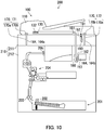
FIG. 10 is a schematic cross-sectional view illustrating a state in which a cover section is closed in a variation of the image forming apparatus. - [
FIG. 11 ]
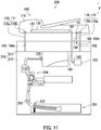
FIG. 11 is a schematic cross-sectional view illustrating a state in which the cover section in the variation of the image forming apparatus has moved upward in the vertical direction V. - The following will describe embodiments of the present invention, with reference to drawings. Some of the elements in the drawings that are the same as each other or that correspond to each other will be referred to by using the same reference characters, and the explanations thereof will not be repeated.
- A
reading device 100 representing a first embodiment of the present invention will be described with reference toFIGS. 1 to 3 .FIG. 1 is a schematic cross-sectional view of thereading device 100.FIG. 2A is a perspective view of thereading device 100. - As illustrated in
FIGS. 1 and2A , thereading device 100 includes acover section 110, atray 120, and aconveyance section 130. - The
cover section 110 has a hollow shape. Thetray 120 is disposed on the outside of thecover section 110. Thetray 120 is linked to thecover section 110. Thetray 120 has one or more sheets loaded thereon. Each of the sheets may be, for example, sheets of plain paper, copy paper, recycled paper, thin paper, thick paper, glossy paper, or overhead projector (OHP) film. Thecover section 110 is rotatably supported. More specifically, thecover section 110 is supported so as to be rotatable about a rotation axis L. The rotation axis L is the rotation axis of thecover section 110. Thecover section 110 includes arotation edge section 111 and afulcrum edge section 112. Therotation edge section 111 is such an edge section of thecover section 110 that is positioned on a second side in terms of a first direction D1 while thecover section 110 is closed. Thefulcrum edge section 112 is such an edge section of thecover section 110 that is positioned on a first side in terms of the first direction D1 while thecover section 110 is closed. Thefulcrum edge section 112 is disposed along the rotation axis L. In the first embodiment, therotation edge section 111 rotates about thefulcrum edge section 112 as a center. Therotation edge section 111 and thefulcrum edge section 112 each extend in a second direction D2. The second direction D2 is a direction parallel to the rotation axis L of thecover section 110. The first direction D1 is a direction perpendicular to the second direction D2. In the first embodiment, the first direction D1 and the second direction D2 are each a direction parallel to the horizontal direction. - The
conveyance section 130 conveys the sheet. More specifically, theconveyance section 130 conveys the sheet from thetray 120. For example, theconveyance section 130 functions as an auto document feeder (ADF). Theconveyance section 130 is housed in thecover section 110. Theconveyance section 130 includesrollers 131 and afirst driving section 132. - The
rollers 131 include, for example, pickup rollers, separation rollers, conveyance rollers, and ejecting rollers. The pickup rollers forward the sheet loaded on thetray 120 to the inside of thecover section 110. The separation rollers forward the sheet while separating the sheet from one another. The conveyance rollers convey the sheet on the inside of thecover section 110. The ejecting rollers eject the sheet conveyed by the conveyance rollers, to the outside of thecover section 110. - The
first driving section 132 is a driving source that rotates therollers 131. Thefirst driving section 132 rotates therollers 131 so that therollers 131 convey the sheet. More specifically, each of the pairs ofrollers 131 conveys the sheet by rotating while having the sheet held therebetween. Thefirst driving section 132 may be a motor, for example. - The
reading device 100 further includes animage reading section 140. - The
image reading section 140 includes an opposingsection 141, aloading section 142, areading section 143, and asecond driving section 144. - The opposing
section 141 is arranged in a location so as to be able to oppose the sheet conveyed by theconveyance section 130. The opposingsection 141 is arranged on a conveyance path of the sheet conveyed by theconveyance section 130. The opposingsection 141 may be a layer of contact glass, for example. It is possible to load any sheet on theloading section 142. Theloading section 142 is arranged on the second side in terms of the second direction D2 with respect to the opposingsection 141. Theloading section 142 may be a layer of contact glass, for example. - The
reading section 143 reads an image formed on any sheet. More specifically, thereading section 143 reads an image formed on each of the sheets conveyed by theconveyance section 130. While thecover section 110 is closed, thereading section 143 reads the image formed on a sheet conveyed by theconveyance section 130. Also, thereading section 143 reads an image formed on a sheet loaded on theloading section 142. "Reading an image" denotes obtaining image data representing the image by scanning the image. - For example, the
reading section 143 may be a contact image sensor (CIS). For example, thereading section 143 includes a light emitting section such as a light emitting diode (LED) and an imaging section such as an image sensor. Thereading section 143 scans the image formed on the sheet by employing the light emitting section and the imaging section. - The
reading section 143 is arranged below the opposingsection 141. Further, thereading section 143 is arranged below theloading section 142. Thereading section 143 is supported so as to be movable in the second direction D2. - As a result of the
conveyance section 130 conveying the sheet while thereading section 143 is positioned beneath the opposingsection 141, thereading section 143 reads the image formed on the sheet. In this situation, while the sheet passes over the opposingsection 141, thereading section 143 reads the image formed on the sheet. - As a result of the
reading section 143 moving along theloading section 142 while the sheet is loaded on theloading section 142, thereading section 143 reads the image formed on the sheet. In this situation, while moving along theloading section 142, thereading section 143 reads the image formed on the sheet. - The
second driving section 144 is a driving source that moves thereading section 143. Thesecond driving section 144 may be a motor, for example. - The
reading device 100 further includes aninput section 151,storage 152, and acontroller 153. - The
input section 151 receives an instruction input to thereading device 100. Via theinput section 151, for example, an instruction indicating that the image formed on the sheet should be read is input. Theinput section 151 includes, for example, either or both a touch panel and a group of operation keys. - The
storage 152 includes a storage device. The storage device includes a main storage device (e.g., semiconductor memory) such as read only memory (ROM) and random access memory (RAM) and may further include an auxiliary storage device (e.g., a hard disk drive). Either or both the main storage device and the auxiliary storage device store therein various types of computer programs to be executed by thecontroller 153. - The
controller 153 includes a processor such as a central processing unit (CPU) and a micro processing unit (MPU). Thecontroller 153 controls each element of thereading device 100. More specifically, by executing the computer programs stored in one or more storage devices, the processor of thecontroller 153 controls theconveyance section 130 and thereading section 143. Even more specifically, in the first embodiment, thecontroller 153 controls thefirst driving section 132, thereading section 143, and thesecond driving section 144. - The
controller 153 controls thefirst driving section 132 so that thefirst driving section 132 rotates therollers 131 to convey the sheet. Further, thecontroller 153 controls thereading section 143 so that thereading section 143 reads the image formed on the sheet. Further, thecontroller 153 controls thesecond driving section 144 so that thesecond driving section 144 moves thereading section 143. - The
reading device 100 further includes acasing 160. Thecasing 160 has a hollow shape. Thecasing 160 houses therein theimage reading section 140, thestorage 152, and thecontroller 153. - The
casing 160 includes aceiling section 161, a first opening section 162, and asecond opening section 163. Theceiling section 161 is a plate-like member. Theceiling section 161 is arranged in a top section of thecasing 160. Theceiling section 161, the opposingsection 141, and theloading section 142 close the top section of thecasing 160. - The first opening section 162 and the
second opening section 163 are arranged in the top section of thecasing 160. The first opening section 162 and thesecond opening section 163 are formed in theceiling section 161. The first opening section 162 and thesecond opening section 163 allow communication between the outside of thecasing 160 and the inside of thecasing 160. The first opening section 162 and thesecond opening section 163 are spaced apart from each other in the second direction D2. The first opening section 162 is arranged with the opposingsection 141. The first opening section 162 is closed by the opposingsection 141. Thesecond opening section 163 is arranged with theloading section 142. Thesecond opening section 163 is closed by theloading section 142. As a result, the top surface of the opposingsection 141 and the top surface of theloading section 142 are exposed to the outside of thecasing 160 through the top section of thecasing 160. - The
casing 160 further includes a pair of casing bores 164 and a throughhole 165. Each of the paired casing bores 164 and the throughhole 165 is formed in the top section of thecasing 160. Each of the paired casing bores 164 and the throughhole 165 is formed in theceiling section 161. The paired casing bores 164 and the throughhole 165 allow communication between the outside of thecasing 160 and the inside of thecasing 160. Each of the paired casing bores 164 and the throughhole 165 extends in the vertical direction V. The paired casing bores 164 and the throughhole 165 are arranged in the edge section of thecasing 160 positioned on the first side in terms of the first direction D1. The paired casing bores 164 and the throughhole 165 are spaced apart from each other in the second direction D2. Further, the throughhole 165 is arranged between the paired casing bores 164. In this situation, the paired casing bores 164 may each be a bottomless bore. In other words, the paired casing bores 164 may each allow communication between the inside of the casing bore 164 and the outside of the casing bore 164. Conversely, the paired casing bores 164 may each be a bore having a bottom. In other words, the paired casing bores 164 do not necessarily have to allow communication between the inside of the casing bores 164 and the outside of the casing bores 164. - Each of the paired casing bores 164 is located opposite to the
cover section 110. More specifically, each of the paired casing bores 164 is located opposite to thefulcrum edge section 112 of thecover section 110. Further, the throughhole 165 opposes thecover section 110. More specifically, the throughhole 165 is located opposite to thefulcrum edge section 112 of thecover section 110. - The paired casing bores 164 include a first casing bore 164a and a second casing bore 164b. The first casing bore 164a is arranged on a first side of the
casing 160 in terms of the second direction D2. The second casing bore 164b is arranged on a second side of thecasing 160 in terms of the second direction D2. - The
input section 151 is arranged on the second side of thecasing 160 in terms of the first direction D1. Accordingly, a user operates theinput section 151 from the second side of thecasing 160 in terms of the first direction D1. - It is possible to place the
cover section 110 on thecasing 160. While thecover section 110 is placed on thecasing 160, thecover section 110 is located opposite to the opposingsection 141 and theloading section 142. - It is possible to place a sheet between the
cover section 110 and thecasing 160. While thecover section 110 is closed and the sheet is spaced between thecover section 110 and thecasing 160, thereading section 143 reads an image formed on the sheet. - The
reading device 100 further includes a pair of interposedmembers 170. - Next, the interposed
members 170 will be described with reference toFIGS. 2A, 2B , and3 .FIG. 2B is a perspective view of either of the interposedmembers 170.FIG. 3 is a drawing illustrating a manner to use the interposedmembers 170. - The interposed
members 170 in the pair have the same structure as each other. In the following sections, a configuration of one of the interposedmembers 170 in the pair will be described. - As illustrated in
FIGS. 2A and 2B , the interposedmember 170 is interposed between thecover section 110 and thecasing 160. The interposedmember 170 is disposed in one of the casing bores 164. The interposedmember 170 supports thecover section 110 so as to be rotatable and also supports thecover section 110 so as to be movable in the vertical direction V. More specifically, the interposedmember 170 supports thecover section 110 so as to be rotatable about thecasing 160 and also supports thecover section 110 so as to be movable in the vertical direction V with respect to thecasing 160. The interposedmember 170 functions as a fulcrum of the rotation of thecover section 110. - The interposed
member 170 includes afirst member 170a and asecond member 170b. More specifically, each of the paired interposedmembers 170 includes afirst member 170a and asecond member 170b. - The
first member 170a is inserted into the one of the casing bores 164. More specifically, a bottom section of thefirst member 170a is inserted into the casing bore 164. A top section of thefirst member 170a protrudes from thecasing 160. Thefirst member 170a slides along the casing bore 164. Accordingly, thefirst member 170a is supported so as to be movable in the vertical direction V. More specifically, thefirst member 170a is supported by thecasing 160 so as to be movable in the vertical direction V. - The
second member 170b is rotatably attached to thefirst member 170a. The rotation axis L of thecover section 110 is positioned in the location where thesecond member 170b is rotatably attached to thefirst member 170a. Thesecond member 170b is rotatably attached to the top section of thefirst member 170a. Accordingly, thesecond member 170b is arranged above thecasing 160. Further, thecover section 110 is fixed to thesecond member 170b. Thesecond member 170b is fixed to thefulcrum edge section 112 of thecover section 110. Accordingly, thesecond member 170b and thecover section 110 integrally rotate with respect to thefirst member 170a. Further, thesecond member 170b and thecover section 110 integrally rotate with respect to thecasing 160. At that time, thecover section 110 rotates about thesecond member 170b as a center. - The lower end of the
first member 170a has such a size that it is possible to insert thefirst member 170a into the casing bore 164. More specifically, the size of the lower end of thefirst member 170a is smaller than the size of the opening of the casing bore 164. Accordingly, when thefirst member 170a descends after the lower end of thefirst member 170a is arranged above the opening of the casing bore 164, the lower end of thefirst member 170a is inserted into the casing bore 164 via the opening of the casing bore 164. As a result, it is possible to smoothly perform the procedure of inserting thefirst member 170a into the casing bore 164 and attaching thecover section 110 to thecasing 160. - The paired interposed
members 170 include a first interposed member 171 and a second interposed member 172. In the first embodiment, thefirst member 170a of the first interposed member 171 is inserted into the first casing bore 164a. Thefirst member 170a of the second interposed member 172 is inserted into the second casing bore 164b. - When the
cover section 110 rotates, therotation edge section 111 of thecover section 110 moves close to or away from thecasing 160. When thecover section 110 rotates, it is possible to open and close thecover section 110 with respect to thecasing 160. While thecover section 110 is closed, thecover section 110 is placed on thecasing 160. Also, while thecover section 110 is closed, abottom surface 113 of thecover section 110 is located opposite to the opposingsection 141 and theloading section 142, and therotation edge section 111 is in contact with theceiling section 161. On the contrary, while thecover section 110 is open, therotation edge section 111 of thecover section 110 moves away upward in the vertical direction V with respect to thecasing 160. As a result of thecover section 110 opening, it becomes possible to arrange a sheet between thecover section 110 and thecasing 160. After that, thecover section 110 is closed, so that the sheet is scanned. - As illustrated in
FIG. 3 , when thefirst members 170a move in the vertical direction V, thecover section 110 moves together with thefirst members 170a. At that time, thefirst members 170a slide along the casing bores 164. Accordingly, thecover section 110 is supported so as to be movable in the vertical direction V with respect to thecasing 160. For example, when thecover section 110 moves upward in the vertical direction V with respect to thecasing 160 so that the gap between thecover section 110 and thecasing 160 becomes widened, it is possible to place a thick book B between thecasing 160 and thecover section 110. As a result, it is possible to have the thick book B scanned and to have an image read from the book B by thereading section 143 housed in thecasing 160. - The
reading device 100 further includes acable 180 and a linkingmember 190. - Next, the
cable 180 will be described with reference toFIGS. 4A and5A .FIG. 4A is a perspective view taken at the IV-IV cross-section inFIG. 1 . The linkingmember 190 is omitted fromFIG. 4A .FIG. 5A is a schematic cross-sectional view illustrating a state in which thecover section 110 is closed. - As illustrated in
FIG. 4A and5A , thecable 180 electrically connects theconveyance section 130 and thecontroller 153 to each other. Thecable 180 is connected to theconveyance section 130 and to thecontroller 153. More specifically, thecable 180 is connected to thefirst driving section 132 of theconveyance section 130 and to thecontroller 153. For example, thecable 180 is connected to theconveyance section 130 via asubstrate 133. Further, thecable 180 transfers a control signal output by thecontroller 153 to the conveyance section 130 (the first driving section 132). The control signal is, for example, a signal indicating that thefirst driving section 132 should be operated so that theconveyance section 130 conveys a sheet. In the first embodiment, thecable 180 is a flat cable. Further, thecable 180 is flexible. In other words, thecable 180 includes a flexible member. Thecable 180 has, for example, a structure in which a plurality of conductors each covered by electrically-insulative coating are integrally formed in a belt-like shape. - The
cable 180 is connected to theconveyance section 130 on the inside of thecover section 110. More specifically, afirst end section 181 of thecable 180 enters the inside of thecover section 110 via ahole 114 formed in thecover section 110 and is connected to theconveyance section 130 on the inside of thecover section 110. - The
hole 114 in thecover section 110 is formed in a bottom section of thecover section 110. Thehole 114 formed in thecover section 110 allows communication between the inside of thecover section 110 and the outside of thecover section 110. Further, thehole 114 formed in thecover section 110 is located opposite to the throughhole 165 formed in thecasing 160. - The
cable 180 is connected to thecontroller 153 on the inside of thecasing 160. More specifically, asecond end section 182 of thecable 180 enters the inside of thecasing 160 via the through hole 165 (seeFIG. 2A ) and is connected to thecontroller 153 on the inside of thecasing 160. - As a result of the
cable 180 being connected to theconveyance section 130 and to thecontroller 153, it is possible to transfer the control signal output by thecontroller 153 to theconveyance section 130 via thecable 180. - The
cable 180 is arranged in thefulcrum edge section 112 of the cover section 110 (seeFIG. 2A ). Further, thecable 180 is arranged in a position apart from the interposedmembers 170 with intervals in the extending direction of the rotation axis L of thesecond member 170b. In the first embodiment, the extending direction of the rotation axis L is the second direction D2. Further, in the first embodiment, thecable 180 is arranged next to the second interposed member 172. - Next, the linking
member 190 will be described with reference toFIGS. 4B and5A .FIG. 4B is another view taken at the IV-IV cross-section inFIG. 1 . Thecable 180 is omitted fromFIG. 4B . - As illustrated in
FIGS. 4B and5A , the linkingmember 190 is linked to thecover section 110 and is also linked to thecasing 160. Accordingly, thecover section 110 and thecasing 160 are linked to each other via the linkingmember 190. - The linking
member 190 has a belt-like shape. The linkingmember 190 is arranged so as to be positioned adjacent to thecable 180. - The linking
member 190 is linked to thecover section 110 on the inside of thecover section 110. More specifically, afirst end section 191 of the linkingmember 190 enters the inside of thecover section 110 via thehole 114 formed in thecover section 110 and is linked to thecover section 110 on the inside of thecover section 110. For example, the linkingmember 190 is linked to thecover section 110 by means of a screw. The expression "the linkingmember 190 is linked to thecover section 110" does not only mean a situation where the linkingmember 190 is directly linked to thecover section 110, but also includes a situation where the linkingmember 190 is indirectly linked to thecover section 110. When the linkingmember 190 is indirectly linked to thecover section 110, for example, the linkingmember 190 is linked to a member supported on thecover section 110. - The linking
member 190 is linked to thecasing 160 on the inside of thecasing 160. More specifically, asecond end section 192 of the linkingmember 190 enters the inside of thecasing 160 via the through hole 165 (seeFIG. 2A ) and is linked to thecasing 160 on the inside of thecasing 160. For example, the linkingmember 190 is linked to thecasing 160 by means of a screw. The expression "the linkingmember 190 is linked to thecasing 160" does not only mean a situation where the linkingmember 190 is directly linked to thecasing 160, but also includes a situation where the linkingmember 190 is indirectly linked to thecasing 160. When the linkingmember 190 is indirectly linked to thecasing 160, for example, the linkingmember 190 is linked to a member supported on thecasing 160. - As a result of the linking
member 190 being linked to thecasing 160 on the inside of thecasing 160, it is possible to cover the linkingmember 190 with thecasing 160. As a result, it is possible to prevent the linkingmember 190 from being damaged. - The linking
member 190 is arranged in thefulcrum edge section 112 of thecover section 110. Further, the linkingmember 190 is arranged in a position apart from the interposedmembers 170 with intervals in the extending direction of the rotation axis L (seeFIG. 2A ) of thesecond member 170b. Accordingly, the linkingmember 190 is arranged in thefulcrum edge section 112 of thecover section 110. As a result, when thecover section 110 is opened or closed, it is possible to prevent the linkingmember 190 from being obstructive. In the first embodiment, the linkingmember 190 is arranged next to the second interposed member 172. - The linking
member 190 is flexible. Further, the linkingmember 190 has electrical conductivity. In other words, the linkingmember 190 includes a flexible member and also includes a member having electrical conductivity. For example, the linkingmember 190 is constituted by a member made from metal. For example, the linkingmember 190 may contain copper. For example, the linkingmember 190 may have a structure in which a member made from metal and having electrical conductivity is fixed to a member made from resin. - Because the linking
member 190 is flexible, it is possible to smoothly perform operation of opening thecover section 110, operation of closing thecover section 110, and operation of moving thecover section 110 each in the vertical direction V. - Further, because the linking
member 190 has electrical conductivity, it is possible to have theconveyance section 130 grounded to thecasing 160 via the linkingmember 190. As a result, it is possible to prevent theconveyance section 130 from having static electricity. - As described above with reference to
FIGS. 4A, 4B , and5A , the linkingmember 190 is linked to thecover section 110 and is also linked to thecasing 160. Accordingly, when thecover section 110 is opened and thecover section 110 is detached from thecasing 160, the linkingmember 190 becomes taut and is able to restrain the opening motion of thecover section 110. As a result, it is possible to prevent thecover section 110 from being detached from thecasing 160. In this situation, the expression "the linkingmember 190 becomes taut" means that the linkingmember 190 is stretched tight and is unable to extend further. Further, the expression "thecover section 110 is detached from thecasing 160" means that at least one of thefirst members 170a comes out of the casing bore 164. - Next, dimensions of the interposed
members 170, thecable 180, and the linkingmember 190 will be explained, with reference toFIGS. 5A and 5B. FIG. 5B is a schematic cross-sectional view illustrating a state in which thecover section 110 has moved upward in the vertical direction V. - As illustrated in
FIG. 5A , while thecover section 110 is closed, thefirst members 170a are inserted in the casing bores 164. Further, while thecover section 110 is closed, thecable 180 and the linkingmember 190 are each slack. - As illustrated in
FIG. 5B , when thecover section 110 has moved upward in the vertical direction V, the linkingmember 190 becomes taut while the state in which thefirst members 170a are inserted in the casing bores 164 is maintained. When the linkingmember 190 is taut, thecover section 110 is restrained from moving upward in the vertical direction V. As a result, it is possible to prevent thefirst members 170a from coming out of the casing bores 164, and it is therefore possible to prevent thecover section 110 from being detached from thecasing 160. In this situation, the expression "thefirst members 170a come out of the casing bores 164" means, in other words, that thefirst members 170a are positioned apart from thecasing 160 and are detached from thecasing 160. - Further, when the
cover section 110 has moved upward in the vertical direction V, the linkingmember 190 becomes taut while thecable 180 is slack. In other words, before thecable 180 becomes taut, the linkingmember 190 becomes taut. Accordingly, thecover section 110 is restrained from further moving upward, and thecable 180 is restrained from becoming taut. As a result, it is possible to prevent thecable 180 from being detached from either or both the conveyance section 130 (the substrate 133) and thecontroller 153. The length of the linkingmember 190 being taut is shorter than the length of thecable 180 being taut and is such a length that prevents thefirst members 170a from being positioned apart from thecasing 160. - An
image forming apparatus 200 representing a second embodiment of the present invention will be described with reference toFIGS. 6 and7 .FIG. 6 is a perspective view of theimage forming apparatus 200.FIG. 7 is a schematic cross-sectional view of theimage forming apparatus 200. Theimage forming apparatus 200 according to the second embodiment is obtained by adding an image forming function to thereading device 100 of the first embodiment. - As illustrated in
FIGS. 6 and7 , theimage forming apparatus 200 includes thereading device 100, acassette 201, afeed roller 202,conveyance rollers 203, animage forming section 204,ejection rollers 205, athird driving section 206, and acasing 210. - The
cassette 201 houses one or more sheets therein. Thefeed roller 202 feeds the sheets in thecassette 201. Theconveyance rollers 203 forward each of the sheets conveyed from thefeed roller 202 to theimage forming section 204. - The
image forming section 204 forms an image on the sheet. More specifically, theimage forming section 204 forms the image on one of the sheets supplied thereto from thecassette 201. The image is, more specifically, a toner image. Theimage forming section 204 includes a photosensitive drum, a charger, a light exposing section, a developing section, and a transfer section, a cleaner, and a charge eliminating section. The image is formed on the sheet by the photosensitive drum, the charger, the light exposing section, the developing section, and the transfer section. The cleaner removes toner remaining on the surface of the photosensitive drum. The charge eliminating section eliminates electric charges remaining on the surface of the photosensitive drum. Theimage forming section 204 forms the image on the sheet and subsequently forwards the sheet to a fixing section. The fixing section fixed the image onto the sheet by applying heat and pressure. - The
ejection rollers 205 ejects the sheet that has passed through theimage forming section 204 out of thecasing 210. - The
third driving section 206 is a driving source that rotates thefeed roller 202, theconveyance rollers 203, and theejection rollers 205. Thethird driving section 206 conveys the sheet by rotating thefeed roller 202, theconveyance rollers 203, and theejection rollers 205. Thethird driving section 206 is a motor, for example. - The
casing 210 has a hollow shape. Thecasing 210 houses therein theimage reading section 140, thestorage 152, thecontroller 153, thecassette 201, thefeed roller 202, theconveyance rollers 203, theimage forming section 204, theejection rollers 205, and thethird driving section 206. The linkingmember 190 is linked to thecasing 210. - The
casing 210 includes afirst casing section 211 and asecond casing section 212. - The
first casing section 211 functions as thecasing 160 of the first embodiment. Thefirst casing section 211 houses theimage reading section 140 therein. It is possible to place thecover section 110 on thefirst casing section 211. - The
second casing section 212 houses therein thestorage 152, thecontroller 153, thecassette 201, thefeed roller 202, theconveyance rollers 203, theimage forming section 204, theejection rollers 205, and thethird driving section 206. In the first embodiment, thecasing 160 corresponding to thefirst casing section 211 houses therein thestorage 152 and thecontroller 153. In contrast, in the second embodiment, thesecond casing section 212 houses therein thestorage 152 and thecontroller 153. - The
first casing section 211 is placed on thesecond casing section 212. Thefirst casing section 211 is secured to thesecond casing section 212. - The
controller 153 controls each element of theimage forming apparatus 200. Thecontroller 153 controls the conveyance section 130 (the first driving section 132), thereading section 143, thesecond driving section 144, theimage forming section 204, and thethird driving section 206. - Next, the location in which the
cable 180 is arranged and the location in which the linkingmember 190 is arranged will be explained with reference toFIG. 8. FIG. 8 is a schematic cross-sectional view illustrating a state in which thecover section 110 is closed. - As illustrated in
FIG. 8 , thesecond end section 182 of thecable 180 is connected to thecontroller 153 on the inside of thesecond casing section 212. More specifically, thesecond end section 182 of thecable 180 enters the inside of thesecond casing section 212 via thefirst casing section 211 and is connected to thecontroller 153 on the inside of thesecond casing section 212. - The linking
member 190 is linked to thesecond casing section 212. The linkingmember 190 is linked to thesecond casing section 212 on the inside of thesecond casing section 212. More specifically, thesecond end section 192 of the linkingmember 190 enters the inside of thesecond casing section 212 via thefirst casing section 211 and is linked to thesecond casing section 212 on the inside of thesecond casing section 212. In this situation, the expression "the linkingmember 190 is linked to thesecond casing section 212" does not only mean a situation where the linkingmember 190 is directly linked to thesecond casing section 212, but also includes a situation where the linkingmember 190 is indirectly linked to thesecond casing section 212. When the linkingmember 190 is indirectly linked to thesecond casing section 212, for example, the linkingmember 190 is linked to a member supported on thesecond casing section 212. - Next, dimensions of the interposed
members 170, thecable 180, and the linkingmember 190 will be explained, with reference toFIGS. 8 and9. FIG. 9 is a schematic cross-sectional view illustrating a state in which thecover section 110 has moved upward in the vertical direction V. - As illustrated in
FIG. 8 , the pair of interposedmembers 170 is interposed between thefirst casing section 211 and thecover section 110. While thecover section 110 is closed, thefirst members 170a are inserted in the casing bores 164. Further, while thecover section 110 is closed, thecable 180 and the linkingmember 190 are each slack. - As illustrated in
FIG. 9 , when thecover section 110 has moved upward in the vertical direction V, the linkingmember 190 becomes taut while the state in which thefirst members 170a are inserted in the casing bores 164 is maintained. As a result, it is possible to prevent thefirst members 170a from coming out of the casing bores 164, and it is therefore possible to prevent thecover section 110 from being detached from thecasing 210. - Further, when the
cover section 110 has moved upward in the vertical direction V, the linkingmember 190 becomes taut while thecable 180 is slack. Accordingly, thecover section 110 is restrained from further moving upward, and thecable 180 is restrained from becoming taut. As a result, it is possible to prevent thecable 180 from being detached from either or both the conveyance section 130 (the substrate 133) and thecontroller 153. - Certain embodiments of the present invention have thus been described with reference to the drawings (
FIGS. 1 to 9 ). It should be noted, however, that the present invention is not limited to the embodiments described above. It is possible to carry out the present invention in various ways (e.g., (1) to (5)) without departing from the gist thereof. Further, it is possible to arrive at various inventions by combining together two or more of the elements of configuration disclosed in the above embodiments as appropriate. For example, one or more of the elements of configuration described in the embodiments may be omitted. To enhance legibility, the drawings are schematically illustrated while a focus is placed on the elements of configuration thereof. The quantity and the like of the elements of configuration illustrated in the drawings may be different from those in actuality for the sake of convenience in the preparation of the drawings. Further, the elements of configuration described in the above embodiments are merely examples, and are not particularly limited. It is possible to apply different variations thereto without substantially departing from advantageous effects of the present invention. -
- (1) In the second embodiment, the
image forming section 204 forms a toner image on a sheet; however, the present invention is not limited to this example. It is sufficient when theimage forming section 204 has a function of forming an image on a sheet. For example, theimage forming section 204 may form an ink image on a sheet. In other words, theimage forming section 204 may be an inkjet-type image forming section. - (2) In the first and the second embodiments, the single liking member, namely the linking
member 190, is provided; however, the present invention is not limited to this example. A plurality of linkingmembers 190 may be provided. In that situation, in the first embodiment, each of the plurality of linkingmembers 190 is linked to thecover section 110 and is also linked to thecasing 160. Further, in that situation, in the second embodiment, each of the plurality of linkingmembers 190 is linked to thecover section 110 and is also linked to thecasing 210. - (3) In the first and the second embodiments, a reading section may be housed in the
cover section 110 of thereading device 100. Hereinafter, the reading section housed in thecover section 110 will be referred to as a housed reading section. In that situation, the housed reading section reads an image from a sheet conveyed by theconveyance section 130. Further, in that situation, it is also acceptable to configure the housed reading section to read an image from one side of a sheet and to configure thereading section 143 to read an image from the other side of the sheet. In that situation, thecable 180 is further connected to the housed reading section. Further, image data read by the housed reading section is transferred to thecontroller 153 via thecable 180. Further, thecontroller 153 transfers a control signal used for controlling the housed reading section to the housed reading section via thecable 180. - (4) In the first and the second embodiments, the linking
member 190 is flexible and also has electrical conductivity; however, the present invention is not limited to this example. It is sufficient when the linkingmember 190 has enough strength not to break while the linkingmember 190 is taut. Further, for example, the linkingmember 190 does not necessarily need to have electrical conductivity while being flexible. In that situation, the linkingmember 190 may be made from resin. - (5) The
image forming apparatus 200 according to the second embodiment illustrated inFIG. 8 may also be configured to have any configuration of (i), (ii), and (iii) described below.- (i) Similarly to the second embodiment, the linking
member 190 is linked to thesecond casing section 212. However, unlike in the second embodiment, thecontroller 153 is housed in thefirst casing section 211. In that situation, thesecond end section 182 of thecable 180 is connected to thecontroller 153 on the inside of thefirst casing section 211. - (ii)
FIG. 10 is a schematic cross-sectional view illustrating a state in which thecover section 110 is closed.FIG. 11 is a schematic cross-sectional view illustrating a state in which thecover section 110 has moved upward in the vertical direction V. As illustrated inFIGS. 10 and11 , similarly to the second embodiment, thecontroller 153 is housed in thesecond casing section 212. However, unlike in the second embodiment, the linkingmember 190 is linked to thefirst casing section 211. In that situation, the linkingmember 190 is linked to thefirst casing section 211 on the inside of thefirst casing section 211. - (iii) Unlike in the second embodiment, the
controller 153 is housed in thefirst casing section 211. Further, unlike in the second embodiment, the linkingmember 190 is linked to thefirst casing section 211. In that situation, thesecond end section 182 of thecable 180 is connected to thecontroller 153 on the inside of thefirst casing section 211. Further, the linkingmember 190 is linked to thefirst casing section 211 on the inside of thefirst casing section 211.
- (i) Similarly to the second embodiment, the linking
- In any of the configurations (i), (ii), and (iii) above, when the
cover section 110 has moved upward in the vertical direction V, the linkingmember 190 becomes taut while the state in which thefirst members 170a are inserted in the casing bores 164 is maintained. As a result, it is possible to prevent thefirst members 170a from coming out of the casing bores 164, and it is therefore possible to prevent thecover section 110 from being detached from thecasing 160. Further, when thecover section 110 has moved upward in the vertical direction V, the linkingmember 190 becomes taut while thecable 180 is slack. As a result, it is possible to prevent thecable 180 from being detached from either of both the conveyance section 130 (the substrate 133) and thecontroller 153. - The present invention is applicable to the fields of reading devices and image forming apparatuses.
Claims (9)
- A reading device comprising:a reading section configured to read an image formed on a sheet;a casing housing the reading section therein;a cover section capable of being placed on the casing;a conveyance section housed in the cover section and configured to convey the sheet;an interposed member interposed between the cover section and the casing;a controller housed in the casing and configured to control the conveyance section;a cable that is connected to the controller, is also connected to the conveyance section, and is configured to transfer a control signal output by the controller to the conveyance section; anda linking member that is linked to the cover section and is also linked to the casing, whereinthe casing has a casing bore located therein for placement of the interposed member,the interposed member includes a first member inserted in the casing bore and supported so as to be movable in a vertical direction and a second member rotatably attached to the first member, andthe cover section is fixed to the second member.
- The reading device according to claim 1, wherein
the linking member is flexible. - The reading device according to claim 1, wherein
the linking member has electrical conductivity. - The reading device according to claim 1, wherein
the linking member is linked to the casing on an inside of the casing. - The reading device according to claim 1, wherein
the linking member has such a length that the linking member is able to become taut while a state in which the first member is inserted in the casing bore is maintained. - The reading device according to claim 1, wherein
the linking member has such a length that the linking member is able to become taut while the cable is slack. - The reading device according to claim 1, wherein
the linking member is arranged in a position apart from the interposed member with an interval in an extending direction of a rotation axis of the second member. - An image forming apparatus comprising:the reading device according to claim 1; andan image forming section configured to form an image on a sheet, whereinthe controller is further configured to control the image forming section, andthe casing further houses the image forming section therein.
- The reading device according to claim 1, wherein
a rotation axis of the cover section is positioned in a location where the second member is rotatably attached to the first member, and
the cable and the linking member are each arranged in a position apart from the interposed member with an interval in an extending direction of the rotation axis.
Applications Claiming Priority (2)
| Application Number | Priority Date | Filing Date | Title |
|---|---|---|---|
| JP2017219980 | 2017-11-15 | ||
| PCT/JP2018/039495 WO2019097968A1 (en) | 2017-11-15 | 2018-10-24 | Reading device and image forming apparatus |
Publications (3)
| Publication Number | Publication Date |
|---|---|
| EP3713205A1 true EP3713205A1 (en) | 2020-09-23 |
| EP3713205A4 EP3713205A4 (en) | 2021-07-28 |
| EP3713205B1 EP3713205B1 (en) | 2024-09-18 |
Family
ID=66539744
Family Applications (1)
| Application Number | Title | Priority Date | Filing Date |
|---|---|---|---|
| EP18879709.6A Active EP3713205B1 (en) | 2017-11-15 | 2018-10-24 | Reading device and image forming apparatus |
Country Status (5)
| Country | Link |
|---|---|
| US (1) | US10855862B2 (en) |
| EP (1) | EP3713205B1 (en) |
| JP (1) | JP6835250B2 (en) |
| CN (1) | CN110521196B (en) |
| WO (1) | WO2019097968A1 (en) |
Families Citing this family (1)
| Publication number | Priority date | Publication date | Assignee | Title |
|---|---|---|---|---|
| JP7615105B2 (en) * | 2022-10-25 | 2025-01-16 | キヤノン株式会社 | Image reading device and recording device |
Family Cites Families (12)
| Publication number | Priority date | Publication date | Assignee | Title |
|---|---|---|---|---|
| JP2001197232A (en) * | 2000-01-06 | 2001-07-19 | Canon Inc | Document reading device and image forming device |
| JP2007088681A (en) * | 2005-09-21 | 2007-04-05 | Seiko Epson Corp | Connecting mechanism and image reading apparatus |
| JP4797691B2 (en) * | 2006-02-27 | 2011-10-19 | 村田機械株式会社 | Image reading device |
| JP5152225B2 (en) * | 2010-02-26 | 2013-02-27 | ブラザー工業株式会社 | Image reading device |
| JP4947178B2 (en) | 2010-03-25 | 2012-06-06 | ブラザー工業株式会社 | Image reading device |
| JP4947177B2 (en) * | 2010-03-25 | 2012-06-06 | ブラザー工業株式会社 | Image reading device |
| JP5003781B2 (en) * | 2010-03-25 | 2012-08-15 | ブラザー工業株式会社 | Compound machine |
| JP5834737B2 (en) * | 2011-10-03 | 2015-12-24 | 富士ゼロックス株式会社 | Image reading device |
| JP5873845B2 (en) * | 2013-07-10 | 2016-03-01 | 京セラドキュメントソリューションズ株式会社 | HINGE STRUCTURE, IMAGE READING DEVICE HAVING THE HINGE STRUCTURE, AND IMAGE FORMING DEVICE |
| JP6135506B2 (en) * | 2013-12-27 | 2017-05-31 | ブラザー工業株式会社 | Sheet processing device |
| JP6394198B2 (en) * | 2014-09-01 | 2018-09-26 | ブラザー工業株式会社 | Image reading apparatus and manufacturing method thereof |
| JP6554885B2 (en) * | 2015-04-14 | 2019-08-07 | 富士ゼロックス株式会社 | Image reading apparatus and image forming apparatus |
-
2018
- 2018-10-24 JP JP2019553773A patent/JP6835250B2/en active Active
- 2018-10-24 CN CN201880024453.4A patent/CN110521196B/en active Active
- 2018-10-24 WO PCT/JP2018/039495 patent/WO2019097968A1/en not_active Ceased
- 2018-10-24 US US16/604,007 patent/US10855862B2/en active Active
- 2018-10-24 EP EP18879709.6A patent/EP3713205B1/en active Active
Also Published As
| Publication number | Publication date |
|---|---|
| WO2019097968A1 (en) | 2019-05-23 |
| EP3713205A4 (en) | 2021-07-28 |
| JP6835250B2 (en) | 2021-02-24 |
| US10855862B2 (en) | 2020-12-01 |
| CN110521196B (en) | 2022-02-25 |
| US20200036848A1 (en) | 2020-01-30 |
| CN110521196A (en) | 2019-11-29 |
| JPWO2019097968A1 (en) | 2020-02-27 |
| EP3713205B1 (en) | 2024-09-18 |
Similar Documents
| Publication | Publication Date | Title |
|---|---|---|
| US8814454B2 (en) | Image processing device | |
| US8792146B2 (en) | Image reading apparatus | |
| US8619273B2 (en) | Multifunction apparatus | |
| US8564857B2 (en) | Image reading apparatus | |
| JP2010064805A (en) | Paper feeder and image forming device having the same | |
| US9499365B2 (en) | Sheet feeding device and image forming apparatus | |
| US10855862B2 (en) | Reading device and image forming apparatus | |
| US9323201B2 (en) | Sheet processing apparatus having hinge | |
| CN108388091A (en) | Image processing apparatus | |
| KR101297178B1 (en) | The image forming apparatus | |
| US20190062090A1 (en) | Stacking apparatus and feeding apparatus | |
| US12541169B2 (en) | Image forming apparatus | |
| JP2001334725A (en) | Image forming device | |
| US9247088B2 (en) | Image forming apparatus | |
| JP7512737B2 (en) | Image forming device | |
| US8849148B2 (en) | Electronic apparatus having pivotable support member for supporting electric circuit board | |
| JP7159906B2 (en) | Fixing device and image forming device | |
| JP2021077947A (en) | Image reading device and image forming apparatus | |
| JP2016163013A (en) | Connection device and image forming apparatus | |
| CN102992055A (en) | Paper feeding device | |
| JPH04257474A (en) | printing device | |
| KR20080066233A (en) | Image Forming Device |
Legal Events
| Date | Code | Title | Description |
|---|---|---|---|
| STAA | Information on the status of an ep patent application or granted ep patent |
Free format text: STATUS: THE INTERNATIONAL PUBLICATION HAS BEEN MADE |
|
| PUAI | Public reference made under article 153(3) epc to a published international application that has entered the european phase |
Free format text: ORIGINAL CODE: 0009012 |
|
| STAA | Information on the status of an ep patent application or granted ep patent |
Free format text: STATUS: REQUEST FOR EXAMINATION WAS MADE |
|
| 17P | Request for examination filed |
Effective date: 20191014 |
|
| AK | Designated contracting states |
Kind code of ref document: A1 Designated state(s): AL AT BE BG CH CY CZ DE DK EE ES FI FR GB GR HR HU IE IS IT LI LT LU LV MC MK MT NL NO PL PT RO RS SE SI SK SM TR |
|
| AX | Request for extension of the european patent |
Extension state: BA ME |
|
| DAV | Request for validation of the european patent (deleted) | ||
| DAX | Request for extension of the european patent (deleted) | ||
| A4 | Supplementary search report drawn up and despatched |
Effective date: 20210625 |
|
| RIC1 | Information provided on ipc code assigned before grant |
Ipc: H04N 1/00 20060101AFI20210621BHEP Ipc: G03B 27/62 20060101ALI20210621BHEP Ipc: G03G 15/00 20060101ALI20210621BHEP Ipc: G03G 21/16 20060101ALI20210621BHEP Ipc: H04N 1/10 20060101ALI20210621BHEP |
|
| STAA | Information on the status of an ep patent application or granted ep patent |
Free format text: STATUS: EXAMINATION IS IN PROGRESS |
|
| 17Q | First examination report despatched |
Effective date: 20220204 |
|
| P01 | Opt-out of the competence of the unified patent court (upc) registered |
Effective date: 20230420 |
|
| GRAP | Despatch of communication of intention to grant a patent |
Free format text: ORIGINAL CODE: EPIDOSNIGR1 |
|
| STAA | Information on the status of an ep patent application or granted ep patent |
Free format text: STATUS: GRANT OF PATENT IS INTENDED |
|
| INTG | Intention to grant announced |
Effective date: 20240103 |
|
| GRAJ | Information related to disapproval of communication of intention to grant by the applicant or resumption of examination proceedings by the epo deleted |
Free format text: ORIGINAL CODE: EPIDOSDIGR1 |
|
| STAA | Information on the status of an ep patent application or granted ep patent |
Free format text: STATUS: EXAMINATION IS IN PROGRESS |
|
| INTC | Intention to grant announced (deleted) | ||
| GRAP | Despatch of communication of intention to grant a patent |
Free format text: ORIGINAL CODE: EPIDOSNIGR1 |
|
| STAA | Information on the status of an ep patent application or granted ep patent |
Free format text: STATUS: GRANT OF PATENT IS INTENDED |
|
| INTG | Intention to grant announced |
Effective date: 20240603 |
|
| GRAS | Grant fee paid |
Free format text: ORIGINAL CODE: EPIDOSNIGR3 |
|
| GRAA | (expected) grant |
Free format text: ORIGINAL CODE: 0009210 |
|
| STAA | Information on the status of an ep patent application or granted ep patent |
Free format text: STATUS: THE PATENT HAS BEEN GRANTED |
|
| AK | Designated contracting states |
Kind code of ref document: B1 Designated state(s): AL AT BE BG CH CY CZ DE DK EE ES FI FR GB GR HR HU IE IS IT LI LT LU LV MC MK MT NL NO PL PT RO RS SE SI SK SM TR |
|
| REG | Reference to a national code |
Ref country code: GB Ref legal event code: FG4D |
|
| REG | Reference to a national code |
Ref country code: CH Ref legal event code: EP |
|
| REG | Reference to a national code |
Ref country code: DE Ref legal event code: R096 Ref document number: 602018074599 Country of ref document: DE |
|
| REG | Reference to a national code |
Ref country code: IE Ref legal event code: FG4D |
|
| REG | Reference to a national code |
Ref country code: LT Ref legal event code: MG9D |
|
| PG25 | Lapsed in a contracting state [announced via postgrant information from national office to epo] |
Ref country code: NO Free format text: LAPSE BECAUSE OF FAILURE TO SUBMIT A TRANSLATION OF THE DESCRIPTION OR TO PAY THE FEE WITHIN THE PRESCRIBED TIME-LIMIT Effective date: 20241218 |
|
| PG25 | Lapsed in a contracting state [announced via postgrant information from national office to epo] |
Ref country code: GR Free format text: LAPSE BECAUSE OF FAILURE TO SUBMIT A TRANSLATION OF THE DESCRIPTION OR TO PAY THE FEE WITHIN THE PRESCRIBED TIME-LIMIT Effective date: 20241219 Ref country code: FI Free format text: LAPSE BECAUSE OF FAILURE TO SUBMIT A TRANSLATION OF THE DESCRIPTION OR TO PAY THE FEE WITHIN THE PRESCRIBED TIME-LIMIT Effective date: 20240918 |
|
| PG25 | Lapsed in a contracting state [announced via postgrant information from national office to epo] |
Ref country code: BG Free format text: LAPSE BECAUSE OF FAILURE TO SUBMIT A TRANSLATION OF THE DESCRIPTION OR TO PAY THE FEE WITHIN THE PRESCRIBED TIME-LIMIT Effective date: 20240918 |
|
| PG25 | Lapsed in a contracting state [announced via postgrant information from national office to epo] |
Ref country code: LV Free format text: LAPSE BECAUSE OF FAILURE TO SUBMIT A TRANSLATION OF THE DESCRIPTION OR TO PAY THE FEE WITHIN THE PRESCRIBED TIME-LIMIT Effective date: 20240918 |
|
| PG25 | Lapsed in a contracting state [announced via postgrant information from national office to epo] |
Ref country code: HR Free format text: LAPSE BECAUSE OF FAILURE TO SUBMIT A TRANSLATION OF THE DESCRIPTION OR TO PAY THE FEE WITHIN THE PRESCRIBED TIME-LIMIT Effective date: 20240918 |
|
| REG | Reference to a national code |
Ref country code: NL Ref legal event code: MP Effective date: 20240918 |
|
| PG25 | Lapsed in a contracting state [announced via postgrant information from national office to epo] |
Ref country code: RS Free format text: LAPSE BECAUSE OF FAILURE TO SUBMIT A TRANSLATION OF THE DESCRIPTION OR TO PAY THE FEE WITHIN THE PRESCRIBED TIME-LIMIT Effective date: 20241218 |
|
| PG25 | Lapsed in a contracting state [announced via postgrant information from national office to epo] |
Ref country code: RS Free format text: LAPSE BECAUSE OF FAILURE TO SUBMIT A TRANSLATION OF THE DESCRIPTION OR TO PAY THE FEE WITHIN THE PRESCRIBED TIME-LIMIT Effective date: 20241218 Ref country code: NO Free format text: LAPSE BECAUSE OF FAILURE TO SUBMIT A TRANSLATION OF THE DESCRIPTION OR TO PAY THE FEE WITHIN THE PRESCRIBED TIME-LIMIT Effective date: 20241218 Ref country code: LV Free format text: LAPSE BECAUSE OF FAILURE TO SUBMIT A TRANSLATION OF THE DESCRIPTION OR TO PAY THE FEE WITHIN THE PRESCRIBED TIME-LIMIT Effective date: 20240918 Ref country code: HR Free format text: LAPSE BECAUSE OF FAILURE TO SUBMIT A TRANSLATION OF THE DESCRIPTION OR TO PAY THE FEE WITHIN THE PRESCRIBED TIME-LIMIT Effective date: 20240918 Ref country code: GR Free format text: LAPSE BECAUSE OF FAILURE TO SUBMIT A TRANSLATION OF THE DESCRIPTION OR TO PAY THE FEE WITHIN THE PRESCRIBED TIME-LIMIT Effective date: 20241219 Ref country code: FI Free format text: LAPSE BECAUSE OF FAILURE TO SUBMIT A TRANSLATION OF THE DESCRIPTION OR TO PAY THE FEE WITHIN THE PRESCRIBED TIME-LIMIT Effective date: 20240918 Ref country code: BG Free format text: LAPSE BECAUSE OF FAILURE TO SUBMIT A TRANSLATION OF THE DESCRIPTION OR TO PAY THE FEE WITHIN THE PRESCRIBED TIME-LIMIT Effective date: 20240918 |
|
| REG | Reference to a national code |
Ref country code: AT Ref legal event code: MK05 Ref document number: 1725668 Country of ref document: AT Kind code of ref document: T Effective date: 20240918 |
|
| PG25 | Lapsed in a contracting state [announced via postgrant information from national office to epo] |
Ref country code: NL Free format text: LAPSE BECAUSE OF FAILURE TO SUBMIT A TRANSLATION OF THE DESCRIPTION OR TO PAY THE FEE WITHIN THE PRESCRIBED TIME-LIMIT Effective date: 20240918 |
|
| PG25 | Lapsed in a contracting state [announced via postgrant information from national office to epo] |
Ref country code: IS Free format text: LAPSE BECAUSE OF FAILURE TO SUBMIT A TRANSLATION OF THE DESCRIPTION OR TO PAY THE FEE WITHIN THE PRESCRIBED TIME-LIMIT Effective date: 20250118 Ref country code: PT Free format text: LAPSE BECAUSE OF FAILURE TO SUBMIT A TRANSLATION OF THE DESCRIPTION OR TO PAY THE FEE WITHIN THE PRESCRIBED TIME-LIMIT Effective date: 20250120 |
|
| PG25 | Lapsed in a contracting state [announced via postgrant information from national office to epo] |
Ref country code: SM Free format text: LAPSE BECAUSE OF FAILURE TO SUBMIT A TRANSLATION OF THE DESCRIPTION OR TO PAY THE FEE WITHIN THE PRESCRIBED TIME-LIMIT Effective date: 20240918 Ref country code: RO Free format text: LAPSE BECAUSE OF FAILURE TO SUBMIT A TRANSLATION OF THE DESCRIPTION OR TO PAY THE FEE WITHIN THE PRESCRIBED TIME-LIMIT Effective date: 20240918 |
|
| PG25 | Lapsed in a contracting state [announced via postgrant information from national office to epo] |
Ref country code: ES Free format text: LAPSE BECAUSE OF FAILURE TO SUBMIT A TRANSLATION OF THE DESCRIPTION OR TO PAY THE FEE WITHIN THE PRESCRIBED TIME-LIMIT Effective date: 20240918 |
|
| PG25 | Lapsed in a contracting state [announced via postgrant information from national office to epo] |
Ref country code: AT Free format text: LAPSE BECAUSE OF FAILURE TO SUBMIT A TRANSLATION OF THE DESCRIPTION OR TO PAY THE FEE WITHIN THE PRESCRIBED TIME-LIMIT Effective date: 20240918 Ref country code: EE Free format text: LAPSE BECAUSE OF FAILURE TO SUBMIT A TRANSLATION OF THE DESCRIPTION OR TO PAY THE FEE WITHIN THE PRESCRIBED TIME-LIMIT Effective date: 20240918 |
|
| PG25 | Lapsed in a contracting state [announced via postgrant information from national office to epo] |
Ref country code: PL Free format text: LAPSE BECAUSE OF FAILURE TO SUBMIT A TRANSLATION OF THE DESCRIPTION OR TO PAY THE FEE WITHIN THE PRESCRIBED TIME-LIMIT Effective date: 20240918 Ref country code: CZ Free format text: LAPSE BECAUSE OF FAILURE TO SUBMIT A TRANSLATION OF THE DESCRIPTION OR TO PAY THE FEE WITHIN THE PRESCRIBED TIME-LIMIT Effective date: 20240918 |
|
| PG25 | Lapsed in a contracting state [announced via postgrant information from national office to epo] |
Ref country code: IT Free format text: LAPSE BECAUSE OF FAILURE TO SUBMIT A TRANSLATION OF THE DESCRIPTION OR TO PAY THE FEE WITHIN THE PRESCRIBED TIME-LIMIT Effective date: 20240918 Ref country code: SK Free format text: LAPSE BECAUSE OF FAILURE TO SUBMIT A TRANSLATION OF THE DESCRIPTION OR TO PAY THE FEE WITHIN THE PRESCRIBED TIME-LIMIT Effective date: 20240918 |
|
| REG | Reference to a national code |
Ref country code: CH Ref legal event code: PL |
|
| REG | Reference to a national code |
Ref country code: DE Ref legal event code: R097 Ref document number: 602018074599 Country of ref document: DE |
|
| PG25 | Lapsed in a contracting state [announced via postgrant information from national office to epo] |
Ref country code: MC Free format text: LAPSE BECAUSE OF FAILURE TO SUBMIT A TRANSLATION OF THE DESCRIPTION OR TO PAY THE FEE WITHIN THE PRESCRIBED TIME-LIMIT Effective date: 20240918 |
|
| PG25 | Lapsed in a contracting state [announced via postgrant information from national office to epo] |
Ref country code: DK Free format text: LAPSE BECAUSE OF FAILURE TO SUBMIT A TRANSLATION OF THE DESCRIPTION OR TO PAY THE FEE WITHIN THE PRESCRIBED TIME-LIMIT Effective date: 20240918 |
|
| PG25 | Lapsed in a contracting state [announced via postgrant information from national office to epo] |
Ref country code: BE Free format text: LAPSE BECAUSE OF NON-PAYMENT OF DUE FEES Effective date: 20241031 Ref country code: LU Free format text: LAPSE BECAUSE OF NON-PAYMENT OF DUE FEES Effective date: 20241024 |
|
| PG25 | Lapsed in a contracting state [announced via postgrant information from national office to epo] |
Ref country code: CH Free format text: LAPSE BECAUSE OF NON-PAYMENT OF DUE FEES Effective date: 20241031 |
|
| PLBE | No opposition filed within time limit |
Free format text: ORIGINAL CODE: 0009261 |
|
| STAA | Information on the status of an ep patent application or granted ep patent |
Free format text: STATUS: NO OPPOSITION FILED WITHIN TIME LIMIT |
|
| REG | Reference to a national code |
Ref country code: BE Ref legal event code: MM Effective date: 20241031 |
|
| 26N | No opposition filed |
Effective date: 20250619 |
|
| PG25 | Lapsed in a contracting state [announced via postgrant information from national office to epo] |
Ref country code: SE Free format text: LAPSE BECAUSE OF FAILURE TO SUBMIT A TRANSLATION OF THE DESCRIPTION OR TO PAY THE FEE WITHIN THE PRESCRIBED TIME-LIMIT Effective date: 20240918 |
|
| PGFP | Annual fee paid to national office [announced via postgrant information from national office to epo] |
Ref country code: GB Payment date: 20250923 Year of fee payment: 8 |
|
| PGFP | Annual fee paid to national office [announced via postgrant information from national office to epo] |
Ref country code: FR Payment date: 20250924 Year of fee payment: 8 |
|
| PG25 | Lapsed in a contracting state [announced via postgrant information from national office to epo] |
Ref country code: IE Free format text: LAPSE BECAUSE OF NON-PAYMENT OF DUE FEES Effective date: 20241024 |
|
| PGFP | Annual fee paid to national office [announced via postgrant information from national office to epo] |
Ref country code: DE Payment date: 20250923 Year of fee payment: 8 |
|
| PG25 | Lapsed in a contracting state [announced via postgrant information from national office to epo] |
Ref country code: CY Free format text: LAPSE BECAUSE OF FAILURE TO SUBMIT A TRANSLATION OF THE DESCRIPTION OR TO PAY THE FEE WITHIN THE PRESCRIBED TIME-LIMIT; INVALID AB INITIO Effective date: 20181024 |
|
| PG25 | Lapsed in a contracting state [announced via postgrant information from national office to epo] |
Ref country code: HU Free format text: LAPSE BECAUSE OF FAILURE TO SUBMIT A TRANSLATION OF THE DESCRIPTION OR TO PAY THE FEE WITHIN THE PRESCRIBED TIME-LIMIT; INVALID AB INITIO Effective date: 20181024 |
|
| PG25 | Lapsed in a contracting state [announced via postgrant information from national office to epo] |
Ref country code: TR Free format text: LAPSE BECAUSE OF FAILURE TO SUBMIT A TRANSLATION OF THE DESCRIPTION OR TO PAY THE FEE WITHIN THE PRESCRIBED TIME-LIMIT Effective date: 20240918 |
|
| PG25 | Lapsed in a contracting state [announced via postgrant information from national office to epo] |
Ref country code: SI Free format text: LAPSE BECAUSE OF FAILURE TO SUBMIT A TRANSLATION OF THE DESCRIPTION OR TO PAY THE FEE WITHIN THE PRESCRIBED TIME-LIMIT Effective date: 20240918 |
|
| PG25 | Lapsed in a contracting state [announced via postgrant information from national office to epo] |
Ref country code: LT Free format text: LAPSE BECAUSE OF FAILURE TO SUBMIT A TRANSLATION OF THE DESCRIPTION OR TO PAY THE FEE WITHIN THE PRESCRIBED TIME-LIMIT Effective date: 20240918 |