EP3713077B1 - INTEGRATED ELECTRIC DRIVE SYSTEM - Google Patents
INTEGRATED ELECTRIC DRIVE SYSTEM Download PDFInfo
- Publication number
- EP3713077B1 EP3713077B1 EP19211146.6A EP19211146A EP3713077B1 EP 3713077 B1 EP3713077 B1 EP 3713077B1 EP 19211146 A EP19211146 A EP 19211146A EP 3713077 B1 EP3713077 B1 EP 3713077B1
- Authority
- EP
- European Patent Office
- Prior art keywords
- motor
- generator
- electric propulsion
- propulsion system
- electric
- Prior art date
- Legal status (The legal status is an assumption and is not a legal conclusion. Google has not performed a legal analysis and makes no representation as to the accuracy of the status listed.)
- Active
Links
Images

Classifications
-
- H—ELECTRICITY
- H02—GENERATION; CONVERSION OR DISTRIBUTION OF ELECTRIC POWER
- H02P—CONTROL OR REGULATION OF ELECTRIC MOTORS, ELECTRIC GENERATORS OR DYNAMO-ELECTRIC CONVERTERS; CONTROLLING TRANSFORMERS, REACTORS OR CHOKE COILS
- H02P6/00—Arrangements for controlling synchronous motors or other dynamo-electric motors using electronic commutation dependent on the rotor position; Electronic commutators therefor
- H02P6/08—Arrangements for controlling the speed or torque of a single motor
-
- H—ELECTRICITY
- H02—GENERATION; CONVERSION OR DISTRIBUTION OF ELECTRIC POWER
- H02P—CONTROL OR REGULATION OF ELECTRIC MOTORS, ELECTRIC GENERATORS OR DYNAMO-ELECTRIC CONVERTERS; CONTROLLING TRANSFORMERS, REACTORS OR CHOKE COILS
- H02P9/00—Arrangements for controlling electric generators for the purpose of obtaining a desired output
- H02P9/04—Control effected upon non-electric prime mover and dependent upon electric output value of the generator
-
- F—MECHANICAL ENGINEERING; LIGHTING; HEATING; WEAPONS; BLASTING
- F02—COMBUSTION ENGINES; HOT-GAS OR COMBUSTION-PRODUCT ENGINE PLANTS
- F02B—INTERNAL-COMBUSTION PISTON ENGINES; COMBUSTION ENGINES IN GENERAL
- F02B63/00—Adaptations of engines for driving pumps, hand-held tools or electric generators; Portable combinations of engines with engine-driven devices
- F02B63/04—Adaptations of engines for driving pumps, hand-held tools or electric generators; Portable combinations of engines with engine-driven devices for electric generators
- F02B63/042—Rotating electric generators
-
- F—MECHANICAL ENGINEERING; LIGHTING; HEATING; WEAPONS; BLASTING
- F02—COMBUSTION ENGINES; HOT-GAS OR COMBUSTION-PRODUCT ENGINE PLANTS
- F02D—CONTROLLING COMBUSTION ENGINES
- F02D29/00—Controlling engines, such controlling being peculiar to the devices driven thereby, the devices being other than parts or accessories essential to engine operation, e.g. controlling of engines by signals external thereto
- F02D29/06—Controlling engines, such controlling being peculiar to the devices driven thereby, the devices being other than parts or accessories essential to engine operation, e.g. controlling of engines by signals external thereto peculiar to engines driving electric generators
Definitions
- the present disclosure relates to an Integrated Electric Propulsion System, and more particularly to an Integrated Electric Propulsion System having integrated generator-motor controller.
- a variety of devices are known in electric propulsion systems.
- propulsion motors are controlled typically to the speed demand from aircraft controller. Dynamic response of the electric motors can be much higher than that of conventional gas turbines providing new opportunities for more dynamic control of propulsion force for aircraft, which may be used to improve the performance of aircraft.
- EP 3 228 544 relates to a hybrid-electric propulsion system.
- An electric propulsion system includes a prime mover, such as a gas turbine engine, a starter-motor generator, such as a PM generator, configured to be driven by the prime mover to generate electric power, an electric propulsion motor, and an integrated generator-motor controller arranged to control the supply of the electric power to the electric propulsion motor in response to a control signal
- the integrated generator-motor controller includes an active rectifier configured in a first mode to feed-forward to the starter-motor generator a power demand parameter associated with the control signal to control the power output of the starter-motor generator.
- the active rectifier includes a second mode to feed-forward to an inverter a power demand parameter associated with the control signal to control the power output to the electric propulsion motor.
- the electric propulsion system can include an energy storage device, such as a battery, connected to the integrated generator-motor.
- the control signal can include at least one of a motor speed command, a thrust command, a torque command, or a power command.
- the power demand parameter can also include an instantaneous power demand.
- the integrated generator-motor controller is configured to receive input indicative of the speed of the electric propulsion motor, to determine a required torque based on the control signal and the current speed of the motor using the required torque.
- the power demand parameter can be determined using a thrust model.
- the integrated generator-motor controller can be arranged to determine an indicator of electric power generated by the starter-motor generator.
- the power demand parameter can be determined using the indicator of electric power generated by the starter-motor generator.
- the integrated generator-motor controller can be arranged to control an inverter to control the supply of the electric power to the electric propulsion motor and a switching means configured to allow the active rectifier to be selectably connected to the starter-motor generator or to the propulsion motor through the inverter.
- the integrated generator-motor controller can be also be arranged to measure a current of the electric power supplied to the electric motor.
- FIG. 1 a partial view of an exemplary embodiment of an electric propulsion system in accordance with the invention is shown in Fig. 1 and is designated generally by reference character 100.
- FIGs. 2-3 Other embodiments of an electric propulsion system in accordance with the invention, or aspects thereof, are provided in Figs. 2-3 , as will be described.
- the systems of the invention can be used to control power to and from a prime mover, or an energy storage device, such as a battery, and to an electric propulsion motor.
- the electric propulsion system 100 includes a prime mover 102, such as a gas-turbine engine, a starter-motor generator 104, such as a PM generator, configured to be driven by the prime mover 102 to generate electric power, an electric propulsion motor 106, and an integrated generator-motor controller 108 arranged to control the supply of the electric power to the electric propulsion motor 106 in response to a control signal.
- the motor-generator controller 108 also includes feedforward (FF) output to the prime mover controller 107 (EEC) for improved performance.
- EEC prime mover controller
- an energy storage device 114 e.g. battery, as a source of energy for electric start of the prime mover (aircraft engines), and supplemental source of energy for propulsion (and other aircraft loads).
- the integrated generator-motor controller 108 includes an active rectifier 110, fed by the PM generator 104, controlled to regulate the dc link voltage 124.
- the DC link sources the downstream inverter 112 which is controlled to regulate the speed (or torque) of the propulsion motor 106.
- the active rectifier 110 and controller includes a second mode to feed-forward to an inverter 112 a power demand parameter associated with the control signal to control the power output to the electric propulsion motor 106.
- the active rectifier 110 is bi-directional.
- the electric propulsion system 100 includes an energy storage device 114, such as a battery system, connected to the integrated generator-controller 108, at the DC link 124.
- the energy storage device 114 enables the system to use the electric propulsion motor 106 as a generator to harvest energy while wind milling. It also allows harvesting energy during thrust reversal with reverse pitching of propellers of the electric propulsion motor 106.
- the active rectifier 110 allows the system to electric-start the prime mover (engine) with the active rectifier 110 operated as an inverter.
- the active rectifier 110 allows the system used for both the propulsion and starter functions, thus minimizing weight penalty without additional mode-switching contactors.
- energy recovered from the electric propulsion motor 106 during windmilling or thrust reversal with reverse pitching of the propellers can be used to re-charge the energy storage device 114.
- the active rectifier 110 serves as an inverter, eliminating the need for the additional mode-switching contactors between the inverter 112 and propulsion motor 106.
- the integrated generator-motor controller 108 can be arranged to control an inverter 112 to control the supply of the electric power to the electric propulsion motor 106 and a switching means 124 configured to allow the active rectifier 110 to be connected to either the PM starter-motor generator 104 or to the electric propulsion motor 106 through the inverter.
- the integrated generator-motor controller can be also be arranged to measure a current of the electric power supplied to the electric motor 106.
- the configuration discussed above further enables the starter-motor generator 104 to be used to start up the prime mover 102 by using stored energy in the battery system 114 or other electrical power source. As it is unlikely that both the propulsion and the starting functions are used simultaneously, except for in air re-starts, this implementation eliminates the necessity of a dedicated starter for the prime mover 102 and maximizes the usage of the starter-motor generator 104 and the inverter 112.
- the control signal can include at least one of a propulsion motor speed command, a thrust command, a torque command, or a power command 116.
- the power demand parameter can also include an instantaneous power demand.
- the integrated generator-motor controller 108 is configured to receive input 118 indicative of the speed of the electric propulsion motor 106, to determine a required torque based on the control signal and the current speed of the electric propulsion motor 106 using the required torque.
- the power demand parameter can be determined using a thrust model 120.
- the integrated generator-motor controller 108 can be arranged to determine an indicator of electric power generated by the PM starter-motor generator 104 and using the indicator of electric power generated by the PM starter-motor generator 104.
- the feed-forward could also be applied the active rectifier to start boosting the DC link in anticipation of the power demand.
- the integrated generator-motor controller 108 utilizes instantaneous power demand P* which is calculated from the motor speed demand and torque current demand Iq* as a feed forward (FF) compensation for the regulation of the DC link voltage. Actual motor speed and current can also be used as the FF compensation.
- the integrated generator-motor controller 108 also uses DC-link voltage as a source of feedback (FB) compensation 130.
- FF and FB compensations improves the dynamic performance of the generator-active rectifier system as well as maintaining stability.
- the addition of the power feedforward allows for increased commanded speed changes.
- the improved power supply from the generator 104 improves the performance of the propulsion motor as the loop gain is less variable with more stable DC-link voltage.
- the integrated generator-motor controller 108 can be tuned such that the bandwidth of power draw is within the bandwidth of the generator. An addition of command state-filters and/or detuning may be utilized as necessary. This arrangement also reduces the requirement for filter components in the DC-bus.
Landscapes
- Engineering & Computer Science (AREA)
- Chemical & Material Sciences (AREA)
- Combustion & Propulsion (AREA)
- Mechanical Engineering (AREA)
- General Engineering & Computer Science (AREA)
- Power Engineering (AREA)
- Control Of Eletrric Generators (AREA)
Description
- The present disclosure relates to an Integrated Electric Propulsion System, and more particularly to an Integrated Electric Propulsion System having integrated generator-motor controller.
- A variety of devices are known in electric propulsion systems. In electric propulsion systems, propulsion motors are controlled typically to the speed demand from aircraft controller. Dynamic response of the electric motors can be much higher than that of conventional gas turbines providing new opportunities for more dynamic control of propulsion force for aircraft, which may be used to improve the performance of aircraft.
- The conventional methods and systems have generally been considered satisfactory for their intended purpose. However, there is still a need in the art for electric propulsion systems having improved power density and control more efficiency, less weight. There also remains a need in the art for such systems and components that are economically viable. The present disclosure may provide a solution for at least one of these remaining challenges.
EP 3 228 544 relates to a hybrid-electric propulsion system. - An electric propulsion system is provided as claimed in claim 1 and includes a prime mover, such as a gas turbine engine, a starter-motor generator, such as a PM generator, configured to be driven by the prime mover to generate electric power, an electric propulsion motor, and an integrated generator-motor controller arranged to control the supply of the electric power to the electric propulsion motor in response to a control signal, wherein the integrated generator-motor controller includes an active rectifier configured in a first mode to feed-forward to the starter-motor generator a power demand parameter associated with the control signal to control the power output of the starter-motor generator. The active rectifier includes a second mode to feed-forward to an inverter a power demand parameter associated with the control signal to control the power output to the electric propulsion motor. The electric propulsion system can include an energy storage device, such as a battery, connected to the integrated generator-motor.
- The control signal can include at least one of a motor speed command, a thrust command, a torque command, or a power command. The power demand parameter can also include an instantaneous power demand.
- The integrated generator-motor controller is configured to receive input indicative of the speed of the electric propulsion motor, to determine a required torque based on the control signal and the current speed of the motor using the required torque. The power demand parameter can be determined using a thrust model. The integrated generator-motor controller can be arranged to determine an indicator of electric power generated by the starter-motor generator. The power demand parameter can be determined using the indicator of electric power generated by the starter-motor generator.
- The integrated generator-motor controller can be arranged to control an inverter to control the supply of the electric power to the electric propulsion motor and a switching means configured to allow the active rectifier to be selectably connected to the starter-motor generator or to the propulsion motor through the inverter. The integrated generator-motor controller can be also be arranged to measure a current of the electric power supplied to the electric motor.
- These and other features of the systems and methods of the subject disclosure will become more readily apparent to those skilled in the art from the following detailed description of the preferred embodiments taken in conjunction with the drawings.
- So that those skilled in the art to which the subject invention appertains will readily understand how to make and use the devices and methods of the subject invention without undue experimentation, preferred embodiments thereof will be described in detail herein below with reference to certain figures, wherein:
-
Fig. 1 is a block schematic view of an electric propulsion system; -
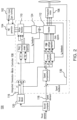
Fig. 2 is a detailed schematic view of the generator ofFig. 1 , showing an example of the generator with an Active Rectifier; and -
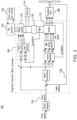
Fig. 3 is a detailed schematic view of the generator ofFig. 1 , showing an example of the generator with alternative Feed Forward signals. - Reference will now be made to the drawings wherein like reference numerals identify similar structural features or aspects of the subject invention. For purposes of explanation and illustration, and not limitation, a partial view of an exemplary embodiment of an electric propulsion system in accordance with the invention is shown in
Fig. 1 and is designated generally byreference character 100. Other embodiments of an electric propulsion system in accordance with the invention, or aspects thereof, are provided inFigs. 2-3 , as will be described. The systems of the invention can be used to control power to and from a prime mover, or an energy storage device, such as a battery, and to an electric propulsion motor. - Referring to
Fig. 1 , theelectric propulsion system 100 includes aprime mover 102, such as a gas-turbine engine, a starter-motor generator 104, such as a PM generator, configured to be driven by theprime mover 102 to generate electric power, anelectric propulsion motor 106, and an integrated generator-motor controller 108 arranged to control the supply of the electric power to theelectric propulsion motor 106 in response to a control signal. The motor-generator controller 108 also includes feedforward (FF) output to the prime mover controller 107 (EEC) for improved performance. Also, includes anenergy storage device 114, e.g. battery, as a source of energy for electric start of the prime mover (aircraft engines), and supplemental source of energy for propulsion (and other aircraft loads). - Referring to
Fig. 2 , the integrated generator-motor controller 108 includes anactive rectifier 110, fed by thePM generator 104, controlled to regulate thedc link voltage 124. The DC link sources thedownstream inverter 112 which is controlled to regulate the speed (or torque) of thepropulsion motor 106. Theactive rectifier 110 and controller includes a second mode to feed-forward to an inverter 112 a power demand parameter associated with the control signal to control the power output to theelectric propulsion motor 106. Theactive rectifier 110 is bi-directional. Theelectric propulsion system 100 includes anenergy storage device 114, such as a battery system, connected to the integrated generator-controller 108, at theDC link 124. Theenergy storage device 114 enables the system to use theelectric propulsion motor 106 as a generator to harvest energy while wind milling. It also allows harvesting energy during thrust reversal with reverse pitching of propellers of theelectric propulsion motor 106. Theactive rectifier 110 allows the system to electric-start the prime mover (engine) with theactive rectifier 110 operated as an inverter. Theactive rectifier 110 allows the system used for both the propulsion and starter functions, thus minimizing weight penalty without additional mode-switching contactors. During aircraft flight, energy recovered from theelectric propulsion motor 106 during windmilling or thrust reversal with reverse pitching of the propellers can be used to re-charge theenergy storage device 114. - With the use of an
active rectifier 110, required to control power from thePM generator 104, the un-desirable low frequency current harmonics (5th, 7th, 11th, 13th of the fundamental generator operating frequency), produced as a result of the rectification process and reflected back into the generator are virtually eliminated. Low frequency current harmonics (5th, 7th, 11th, 13th of the fundamental frequency) that can result in significant generator winding losses will be reduced, requiring less cooling. This also allowsgenerator 104 to be designed for higher power density or reduced weight. The better power quality on the generator-side allows for legacy AC loads to be directly powered by thegenerator 104, if system load architecture requires that. Further, with regards to the engine start functionality, theactive rectifier 110 serves as an inverter, eliminating the need for the additional mode-switching contactors between theinverter 112 andpropulsion motor 106. - The integrated generator-
motor controller 108 can be arranged to control aninverter 112 to control the supply of the electric power to theelectric propulsion motor 106 and a switching means 124 configured to allow theactive rectifier 110 to be connected to either the PM starter-motor generator 104 or to theelectric propulsion motor 106 through the inverter. The integrated generator-motor controller can be also be arranged to measure a current of the electric power supplied to theelectric motor 106. - The configuration discussed above further enables the starter-
motor generator 104 to be used to start up theprime mover 102 by using stored energy in thebattery system 114 or other electrical power source. As it is unlikely that both the propulsion and the starting functions are used simultaneously, except for in air re-starts, this implementation eliminates the necessity of a dedicated starter for theprime mover 102 and maximizes the usage of the starter-motor generator 104 and theinverter 112. - Referring to
Fig. 3 , the control signal can include at least one of a propulsion motor speed command, a thrust command, a torque command, or apower command 116. The power demand parameter can also include an instantaneous power demand. The integrated generator-motor controller 108 is configured to receiveinput 118 indicative of the speed of theelectric propulsion motor 106, to determine a required torque based on the control signal and the current speed of theelectric propulsion motor 106 using the required torque. The power demand parameter can be determined using athrust model 120. The integrated generator-motor controller 108 can be arranged to determine an indicator of electric power generated by the PM starter-motor generator 104 and using the indicator of electric power generated by the PM starter-motor generator 104. The feed-forward could also be applied the active rectifier to start boosting the DC link in anticipation of the power demand. - The integrated generator-
motor controller 108 utilizes instantaneous power demand P* which is calculated from the motor speed demand and torque current demand Iq* as a feed forward (FF) compensation for the regulation of the DC link voltage. Actual motor speed and current can also be used as the FF compensation. The integrated generator-motor controller 108 also uses DC-link voltage as a source of feedback (FB)compensation 130. The combination of FF and FB compensations improves the dynamic performance of the generator-active rectifier system as well as maintaining stability. The addition of the power feedforward allows for increased commanded speed changes. The improved power supply from thegenerator 104 improves the performance of the propulsion motor as the loop gain is less variable with more stable DC-link voltage. The integrated generator-motor controller 108 can be tuned such that the bandwidth of power draw is within the bandwidth of the generator. An addition of command state-filters and/or detuning may be utilized as necessary. This arrangement also reduces the requirement for filter components in the DC-bus. - The methods and systems of the present disclosure, as described above and shown in the drawings, provide for electrical power system with superior properties including increased reliability and stability, and reduced size, weight, complexity, and/or cost. While the apparatus and methods of the subject disclosure have been showing and described with reference to embodiments, those skilled in the art will readily appreciate that changes and/or modifications may be made thereto without departing from the scope of the appended claims.
Claims (15)
- An electric propulsion system comprising:a prime mover (102);a starter-motor generator (104) configured to be driven by the prime mover (102) to generate electric power;an electric propulsion motor (106); andan integrated generator-motor controller (108) arranged to control a supply of the electric power to the electric propulsion motor (106) in response to a control signal, wherein the integrated generator-motor controller (108) includes an active rectifier (110) configured in a first mode to feed-forward to the starter-motor generator (104) a power demand parameter associated with the control signal so as to control a power output of the starter-motor generator (104) in order to start the prime mover (102);characterised in that:the integrated generator-motor controller (108) utilizes DC-link voltage as a source of feedback compensation; andthe integrated generator-motor controller (108) is tuned such that a bandwidth of power draw is within a bandwidth of the starter-motor generator (104).
- The electric propulsion system of claim 1, wherein the active rectifier (110) is configured in a second mode to feed-forward to an inverter (112) a power demand parameter associated with the control signal so as to control the power output of the starter-motor generator (104) to the electric propulsion motor (106) and/or wherein the active rectifier (110) is integrated into the integrated generator-motor controller.
- The electric propulsion system of claim 1 or 2, wherein the control signal comprises at least one of a motor speed command, a thrust command, a torque command or a power command.
- The electric propulsion system of any preceding claim, wherein the power demand parameter comprises an instantaneous power demand.
- The electric propulsion system of any preceding claim, wherein the prime mover (102) is a gas turbine engine.
- The electric propulsion system of any preceding claim, wherein the integrated generator-motor controller (108) is configured to receive input indicative of a speed of the electric propulsion motor (106).
- The electric propulsion system of claim 6, wherein the integrated generator-motor controller (108) is configured to determine a required torque based on the control signal and the speed of the electric propulsion motor.
- The electric propulsion system of claim 7, wherein the power demand parameter is determined using the required torque.
- The electric propulsion system of claim 6, wherein the power demand parameter is determined using a thrust model.
- The electric propulsion system of claim 6, wherein the integrated generator-motor controller (108) is arranged to determine an indicator of electric power generated by the starter-motor generator (104).
- The electric propulsion system of claim 10, wherein the power demand parameter is determined using the indicator of electric power generated by the starter-motor generator.
- The electric propulsion system of any preceding claim, further comprising an energy storage device (114) connected to the integrated generator-motor controller (108) for starting the prime mover (102) using stored energy.
- The electric propulsion system of any preceding claim, wherein the integrated generator-motor controller (108) is arranged to control an inverter to control the supply of the electric power to the electric propulsion motor (106), and preferably further comprising a switching means configured to allow the active rectifier (110) to be selectably connected to the starter-motor generator (104) or to the propulsion motor (106).
- The electric propulsion system of any preceding claim, wherein the integrated generator-motor controller (118) is arranged to measure a current of the electric power supplied to the electric propulsion motor.
- The electric propulsion system of any preceding claim, wherein the starter-motor generator (104) is a PM generator.
Applications Claiming Priority (1)
| Application Number | Priority Date | Filing Date | Title |
|---|---|---|---|
| US16/361,033 US11183956B2 (en) | 2019-03-21 | 2019-03-21 | Integrated electric propulsion system |
Publications (2)
| Publication Number | Publication Date |
|---|---|
| EP3713077A1 EP3713077A1 (en) | 2020-09-23 |
| EP3713077B1 true EP3713077B1 (en) | 2025-04-30 |
Family
ID=68655332
Family Applications (1)
| Application Number | Title | Priority Date | Filing Date |
|---|---|---|---|
| EP19211146.6A Active EP3713077B1 (en) | 2019-03-21 | 2019-11-25 | INTEGRATED ELECTRIC DRIVE SYSTEM |
Country Status (2)
| Country | Link |
|---|---|
| US (1) | US11183956B2 (en) |
| EP (1) | EP3713077B1 (en) |
Families Citing this family (3)
| Publication number | Priority date | Publication date | Assignee | Title |
|---|---|---|---|---|
| US11905026B2 (en) * | 2021-02-12 | 2024-02-20 | Rolls-Royce Corporation | Hybrid propulsion system cockpit interface |
| US12451769B2 (en) | 2023-11-15 | 2025-10-21 | Hamilton Sundstrand Corporation | Multiplexed bi directional converters for hybrid electric aircraft propulsion |
| US12428997B2 (en) | 2024-01-23 | 2025-09-30 | Rtx Corporation | Multi-mode starter control for gas turbine engines |
Citations (1)
| Publication number | Priority date | Publication date | Assignee | Title |
|---|---|---|---|---|
| EP2546969A1 (en) * | 2011-07-14 | 2013-01-16 | Siemens Aktiengesellschaft | Method for controlling a frequency converter and frequency converter |
Family Cites Families (13)
| Publication number | Priority date | Publication date | Assignee | Title |
|---|---|---|---|---|
| US5428275A (en) | 1993-05-12 | 1995-06-27 | Sundstrand Corporation | Controlled starting method for a gas turbine engine |
| KR0177948B1 (en) * | 1995-09-22 | 1999-05-15 | 구자홍 | Inverter Controller for Brushless DC Motor Control |
| GB2451463B (en) | 2007-07-28 | 2012-07-25 | Converteam Technology Ltd | Control methods for VSC active rectifier/inverters under unbalanced operating conditions |
| WO2011100971A2 (en) * | 2010-02-18 | 2011-08-25 | Danfoss Drives A/S | Method for implementing bootstrap-supply charging in a motor controller at energized motor and motor controller using such a method |
| US9048765B2 (en) | 2011-03-29 | 2015-06-02 | Innovus Power, Inc. | Engine powered generator |
| US20130001944A1 (en) | 2011-06-30 | 2013-01-03 | Hickam Christopher D | Starting method/apparatus for series electric drive |
| KR101961106B1 (en) | 2012-03-20 | 2019-03-25 | 삼성전자 주식회사 | Sensorless control method and apparatus thereof |
| WO2014158240A2 (en) * | 2013-03-14 | 2014-10-02 | Rolls-Royce Corporation | Hybrid turbo electric aero-propulsion system control |
| KR102350484B1 (en) * | 2014-12-01 | 2022-01-17 | 삼성전자주식회사 | Moter driving apparatus, airconditioner having the same and control method thereof |
| US20170291712A1 (en) | 2016-04-08 | 2017-10-12 | Hamilton Sundstrand Corporation | Hybrid electric aircraft propulsion incorporating a recuperated prime mover |
| US20180265206A1 (en) | 2017-03-17 | 2018-09-20 | Hamilton Sundstrand Corporation | Variable speed ac bus powered tail cone boundary layer ingestion thruster |
| US10414477B2 (en) | 2017-06-23 | 2019-09-17 | Hamilton Sundstrand Corporation | Pulsed power hybrid electric unmanned underwater vehicle propulsion system |
| US10425029B1 (en) * | 2018-06-01 | 2019-09-24 | Regal Beloit America, Inc. | Motor controller for electric blower motors |
-
2019
- 2019-03-21 US US16/361,033 patent/US11183956B2/en active Active
- 2019-11-25 EP EP19211146.6A patent/EP3713077B1/en active Active
Patent Citations (1)
| Publication number | Priority date | Publication date | Assignee | Title |
|---|---|---|---|---|
| EP2546969A1 (en) * | 2011-07-14 | 2013-01-16 | Siemens Aktiengesellschaft | Method for controlling a frequency converter and frequency converter |
Also Published As
| Publication number | Publication date |
|---|---|
| US11183956B2 (en) | 2021-11-23 |
| EP3713077A1 (en) | 2020-09-23 |
| US20200304047A1 (en) | 2020-09-24 |
Similar Documents
| Publication | Publication Date | Title |
|---|---|---|
| US11850951B2 (en) | Electric propulsion systems | |
| CN110877739B (en) | Operation of hybrid-electric aircraft propulsion systems | |
| US10131441B2 (en) | Aircraft electrical network | |
| Zhang et al. | Overview and development of variable frequency AC generators for more electric aircraft generation system | |
| US7468561B2 (en) | Integrated electrical power extraction for aircraft engines | |
| US11945592B2 (en) | System for converting and transporting electrical energy for the internal hybridization of an aircraft with turbojet engines | |
| US6188591B1 (en) | System for supplying electromotive consumers with electric energy | |
| EP2801719B1 (en) | Aircraft electrical system | |
| JP6248203B2 (en) | Method for starting an aircraft engine | |
| EP3713077B1 (en) | INTEGRATED ELECTRIC DRIVE SYSTEM | |
| EP2040370B1 (en) | Generator for gas turbine engine having main DC bus and accessory AC bus | |
| CN103460585B (en) | The electric energy of airborne vehicle | |
| WO2017066223A1 (en) | Method and apparatus for starting an aircraft engine and operating a power architecture for an aircraft | |
| JP2001500356A (en) | Independent electrical system including prime mover and asynchronous machine with inverter / rectifier | |
| EP3993206B1 (en) | Electrical power system having a dc bus with variable voltage setting | |
| EP4215738B1 (en) | Hybrid power system | |
| US10450044B2 (en) | Electrical power distribution system, method for powering a corresponding task, propulsion system and method for a ship | |
| US10658959B2 (en) | Power supply system with first and second AC voltage generators and respective 6-pulse rectifier units | |
| CN113437742B (en) | Power supply method and system for hybrid aircraft | |
| CN215646182U (en) | Power supply system for hybrid aircraft | |
| US12231073B2 (en) | Propulsion channel for aircraft | |
| Jiao et al. | Topology and Control Method of Aircraft Two-Stage HVDC Integrated Starter-Generator System | |
| Peng et al. | A turboelectric distributed propulsion based on brushless doubly-fed machines | |
| US12428998B2 (en) | Aircraft engine start using multiple common motor controllers | |
| US20240364245A1 (en) | Engine start system with exciter |
Legal Events
| Date | Code | Title | Description |
|---|---|---|---|
| PUAI | Public reference made under article 153(3) epc to a published international application that has entered the european phase |
Free format text: ORIGINAL CODE: 0009012 |
|
| STAA | Information on the status of an ep patent application or granted ep patent |
Free format text: STATUS: THE APPLICATION HAS BEEN PUBLISHED |
|
| AK | Designated contracting states |
Kind code of ref document: A1 Designated state(s): AL AT BE BG CH CY CZ DE DK EE ES FI FR GB GR HR HU IE IS IT LI LT LU LV MC MK MT NL NO PL PT RO RS SE SI SK SM TR |
|
| AX | Request for extension of the european patent |
Extension state: BA ME |
|
| RIN1 | Information on inventor provided before grant (corrected) |
Inventor name: KHERALUWALA, MUSTANSIR Inventor name: HARKE, MICHAEL C. Inventor name: SAWATA, TADASHI |
|
| STAA | Information on the status of an ep patent application or granted ep patent |
Free format text: STATUS: REQUEST FOR EXAMINATION WAS MADE |
|
| 17P | Request for examination filed |
Effective date: 20210323 |
|
| RBV | Designated contracting states (corrected) |
Designated state(s): AL AT BE BG CH CY CZ DE DK EE ES FI FR GB GR HR HU IE IS IT LI LT LU LV MC MK MT NL NO PL PT RO RS SE SI SK SM TR |
|
| STAA | Information on the status of an ep patent application or granted ep patent |
Free format text: STATUS: EXAMINATION IS IN PROGRESS |
|
| 17Q | First examination report despatched |
Effective date: 20210615 |
|
| GRAP | Despatch of communication of intention to grant a patent |
Free format text: ORIGINAL CODE: EPIDOSNIGR1 |
|
| STAA | Information on the status of an ep patent application or granted ep patent |
Free format text: STATUS: GRANT OF PATENT IS INTENDED |
|
| INTG | Intention to grant announced |
Effective date: 20240716 |
|
| GRAJ | Information related to disapproval of communication of intention to grant by the applicant or resumption of examination proceedings by the epo deleted |
Free format text: ORIGINAL CODE: EPIDOSDIGR1 |
|
| STAA | Information on the status of an ep patent application or granted ep patent |
Free format text: STATUS: EXAMINATION IS IN PROGRESS |
|
| INTC | Intention to grant announced (deleted) | ||
| GRAP | Despatch of communication of intention to grant a patent |
Free format text: ORIGINAL CODE: EPIDOSNIGR1 |
|
| STAA | Information on the status of an ep patent application or granted ep patent |
Free format text: STATUS: GRANT OF PATENT IS INTENDED |
|
| INTG | Intention to grant announced |
Effective date: 20241216 |
|
| GRAS | Grant fee paid |
Free format text: ORIGINAL CODE: EPIDOSNIGR3 |
|
| GRAA | (expected) grant |
Free format text: ORIGINAL CODE: 0009210 |
|
| STAA | Information on the status of an ep patent application or granted ep patent |
Free format text: STATUS: THE PATENT HAS BEEN GRANTED |
|
| AK | Designated contracting states |
Kind code of ref document: B1 Designated state(s): AL AT BE BG CH CY CZ DE DK EE ES FI FR GB GR HR HU IE IS IT LI LT LU LV MC MK MT NL NO PL PT RO RS SE SI SK SM TR |
|
| REG | Reference to a national code |
Ref country code: CH Ref legal event code: EP Ref country code: GB Ref legal event code: FG4D |
|
| REG | Reference to a national code |
Ref country code: IE Ref legal event code: FG4D |
|
| REG | Reference to a national code |
Ref country code: DE Ref legal event code: R096 Ref document number: 602019069269 Country of ref document: DE |
|
| REG | Reference to a national code |
Ref country code: NL Ref legal event code: MP Effective date: 20250430 |
|
| REG | Reference to a national code |
Ref country code: AT Ref legal event code: MK05 Ref document number: 1791030 Country of ref document: AT Kind code of ref document: T Effective date: 20250430 |
|
| PG25 | Lapsed in a contracting state [announced via postgrant information from national office to epo] |
Ref country code: PT Free format text: LAPSE BECAUSE OF FAILURE TO SUBMIT A TRANSLATION OF THE DESCRIPTION OR TO PAY THE FEE WITHIN THE PRESCRIBED TIME-LIMIT Effective date: 20250901 Ref country code: ES Free format text: LAPSE BECAUSE OF FAILURE TO SUBMIT A TRANSLATION OF THE DESCRIPTION OR TO PAY THE FEE WITHIN THE PRESCRIBED TIME-LIMIT Effective date: 20250430 Ref country code: FI Free format text: LAPSE BECAUSE OF FAILURE TO SUBMIT A TRANSLATION OF THE DESCRIPTION OR TO PAY THE FEE WITHIN THE PRESCRIBED TIME-LIMIT Effective date: 20250430 |
|
| REG | Reference to a national code |
Ref country code: LT Ref legal event code: MG9D |
|
| PG25 | Lapsed in a contracting state [announced via postgrant information from national office to epo] |
Ref country code: NO Free format text: LAPSE BECAUSE OF FAILURE TO SUBMIT A TRANSLATION OF THE DESCRIPTION OR TO PAY THE FEE WITHIN THE PRESCRIBED TIME-LIMIT Effective date: 20250730 Ref country code: GR Free format text: LAPSE BECAUSE OF FAILURE TO SUBMIT A TRANSLATION OF THE DESCRIPTION OR TO PAY THE FEE WITHIN THE PRESCRIBED TIME-LIMIT Effective date: 20250731 |
|
| PG25 | Lapsed in a contracting state [announced via postgrant information from national office to epo] |
Ref country code: PL Free format text: LAPSE BECAUSE OF FAILURE TO SUBMIT A TRANSLATION OF THE DESCRIPTION OR TO PAY THE FEE WITHIN THE PRESCRIBED TIME-LIMIT Effective date: 20250430 Ref country code: NL Free format text: LAPSE BECAUSE OF FAILURE TO SUBMIT A TRANSLATION OF THE DESCRIPTION OR TO PAY THE FEE WITHIN THE PRESCRIBED TIME-LIMIT Effective date: 20250430 |
|
| PG25 | Lapsed in a contracting state [announced via postgrant information from national office to epo] |
Ref country code: BG Free format text: LAPSE BECAUSE OF FAILURE TO SUBMIT A TRANSLATION OF THE DESCRIPTION OR TO PAY THE FEE WITHIN THE PRESCRIBED TIME-LIMIT Effective date: 20250430 |
|
| PG25 | Lapsed in a contracting state [announced via postgrant information from national office to epo] |
Ref country code: HR Free format text: LAPSE BECAUSE OF FAILURE TO SUBMIT A TRANSLATION OF THE DESCRIPTION OR TO PAY THE FEE WITHIN THE PRESCRIBED TIME-LIMIT Effective date: 20250430 |
|
| PG25 | Lapsed in a contracting state [announced via postgrant information from national office to epo] |
Ref country code: AT Free format text: LAPSE BECAUSE OF FAILURE TO SUBMIT A TRANSLATION OF THE DESCRIPTION OR TO PAY THE FEE WITHIN THE PRESCRIBED TIME-LIMIT Effective date: 20250430 |
|
| PG25 | Lapsed in a contracting state [announced via postgrant information from national office to epo] |
Ref country code: RS Free format text: LAPSE BECAUSE OF FAILURE TO SUBMIT A TRANSLATION OF THE DESCRIPTION OR TO PAY THE FEE WITHIN THE PRESCRIBED TIME-LIMIT Effective date: 20250731 |
|
| PG25 | Lapsed in a contracting state [announced via postgrant information from national office to epo] |
Ref country code: IS Free format text: LAPSE BECAUSE OF FAILURE TO SUBMIT A TRANSLATION OF THE DESCRIPTION OR TO PAY THE FEE WITHIN THE PRESCRIBED TIME-LIMIT Effective date: 20250830 |
|
| PG25 | Lapsed in a contracting state [announced via postgrant information from national office to epo] |
Ref country code: LV Free format text: LAPSE BECAUSE OF FAILURE TO SUBMIT A TRANSLATION OF THE DESCRIPTION OR TO PAY THE FEE WITHIN THE PRESCRIBED TIME-LIMIT Effective date: 20250430 |
|
| PG25 | Lapsed in a contracting state [announced via postgrant information from national office to epo] |
Ref country code: DK Free format text: LAPSE BECAUSE OF FAILURE TO SUBMIT A TRANSLATION OF THE DESCRIPTION OR TO PAY THE FEE WITHIN THE PRESCRIBED TIME-LIMIT Effective date: 20250430 Ref country code: SM Free format text: LAPSE BECAUSE OF FAILURE TO SUBMIT A TRANSLATION OF THE DESCRIPTION OR TO PAY THE FEE WITHIN THE PRESCRIBED TIME-LIMIT Effective date: 20250430 |
|
| PGFP | Annual fee paid to national office [announced via postgrant information from national office to epo] |
Ref country code: FR Payment date: 20251022 Year of fee payment: 7 |
|
| PG25 | Lapsed in a contracting state [announced via postgrant information from national office to epo] |
Ref country code: CZ Free format text: LAPSE BECAUSE OF FAILURE TO SUBMIT A TRANSLATION OF THE DESCRIPTION OR TO PAY THE FEE WITHIN THE PRESCRIBED TIME-LIMIT Effective date: 20250430 |
|
| PG25 | Lapsed in a contracting state [announced via postgrant information from national office to epo] |
Ref country code: EE Free format text: LAPSE BECAUSE OF FAILURE TO SUBMIT A TRANSLATION OF THE DESCRIPTION OR TO PAY THE FEE WITHIN THE PRESCRIBED TIME-LIMIT Effective date: 20250430 |
|
| PG25 | Lapsed in a contracting state [announced via postgrant information from national office to epo] |
Ref country code: RO Free format text: LAPSE BECAUSE OF FAILURE TO SUBMIT A TRANSLATION OF THE DESCRIPTION OR TO PAY THE FEE WITHIN THE PRESCRIBED TIME-LIMIT Effective date: 20250430 Ref country code: SK Free format text: LAPSE BECAUSE OF FAILURE TO SUBMIT A TRANSLATION OF THE DESCRIPTION OR TO PAY THE FEE WITHIN THE PRESCRIBED TIME-LIMIT Effective date: 20250430 |
|
| PG25 | Lapsed in a contracting state [announced via postgrant information from national office to epo] |
Ref country code: IT Free format text: LAPSE BECAUSE OF FAILURE TO SUBMIT A TRANSLATION OF THE DESCRIPTION OR TO PAY THE FEE WITHIN THE PRESCRIBED TIME-LIMIT Effective date: 20250430 |
|
| REG | Reference to a national code |
Ref country code: DE Ref legal event code: R097 Ref document number: 602019069269 Country of ref document: DE |
|
| PLBE | No opposition filed within time limit |
Free format text: ORIGINAL CODE: 0009261 |
|
| STAA | Information on the status of an ep patent application or granted ep patent |
Free format text: STATUS: NO OPPOSITION FILED WITHIN TIME LIMIT |
|
| REG | Reference to a national code |
Ref country code: CH Ref legal event code: L10 Free format text: ST27 STATUS EVENT CODE: U-0-0-L10-L00 (AS PROVIDED BY THE NATIONAL OFFICE) Effective date: 20260311 |
|
| 26N | No opposition filed |
Effective date: 20260202 |