EP3713007A1 - Electrode assembly - Google Patents
Electrode assembly Download PDFInfo
- Publication number
- EP3713007A1 EP3713007A1 EP19891447.5A EP19891447A EP3713007A1 EP 3713007 A1 EP3713007 A1 EP 3713007A1 EP 19891447 A EP19891447 A EP 19891447A EP 3713007 A1 EP3713007 A1 EP 3713007A1
- Authority
- EP
- European Patent Office
- Prior art keywords
- positive electrode
- active material
- nickel
- manganese
- cobalt
- Prior art date
- Legal status (The legal status is an assumption and is not a legal conclusion. Google has not performed a legal analysis and makes no representation as to the accuracy of the status listed.)
- Pending
Links
Images


Classifications
-
- H—ELECTRICITY
- H01—ELECTRIC ELEMENTS
- H01M—PROCESSES OR MEANS, e.g. BATTERIES, FOR THE DIRECT CONVERSION OF CHEMICAL ENERGY INTO ELECTRICAL ENERGY
- H01M10/00—Secondary cells; Manufacture thereof
- H01M10/05—Accumulators with non-aqueous electrolyte
- H01M10/052—Li-accumulators
-
- H—ELECTRICITY
- H01—ELECTRIC ELEMENTS
- H01M—PROCESSES OR MEANS, e.g. BATTERIES, FOR THE DIRECT CONVERSION OF CHEMICAL ENERGY INTO ELECTRICAL ENERGY
- H01M10/00—Secondary cells; Manufacture thereof
- H01M10/05—Accumulators with non-aqueous electrolyte
- H01M10/058—Construction or manufacture
- H01M10/0585—Construction or manufacture of accumulators having only flat construction elements, i.e. flat positive electrodes, flat negative electrodes and flat separators
-
- H—ELECTRICITY
- H01—ELECTRIC ELEMENTS
- H01M—PROCESSES OR MEANS, e.g. BATTERIES, FOR THE DIRECT CONVERSION OF CHEMICAL ENERGY INTO ELECTRICAL ENERGY
- H01M4/00—Electrodes
- H01M4/02—Electrodes composed of, or comprising, active material
- H01M4/13—Electrodes for accumulators with non-aqueous electrolyte, e.g. for lithium-accumulators; Processes of manufacture thereof
- H01M4/131—Electrodes based on mixed oxides or hydroxides, or on mixtures of oxides or hydroxides, e.g. LiCoOx
-
- H—ELECTRICITY
- H01—ELECTRIC ELEMENTS
- H01M—PROCESSES OR MEANS, e.g. BATTERIES, FOR THE DIRECT CONVERSION OF CHEMICAL ENERGY INTO ELECTRICAL ENERGY
- H01M4/00—Electrodes
- H01M4/02—Electrodes composed of, or comprising, active material
- H01M4/36—Selection of substances as active materials, active masses, active liquids
- H01M4/48—Selection of substances as active materials, active masses, active liquids of inorganic oxides or hydroxides
- H01M4/50—Selection of substances as active materials, active masses, active liquids of inorganic oxides or hydroxides of manganese
- H01M4/505—Selection of substances as active materials, active masses, active liquids of inorganic oxides or hydroxides of manganese of mixed oxides or hydroxides containing manganese for inserting or intercalating light metals, e.g. LiMn2O4 or LiMn2OxFy
-
- H—ELECTRICITY
- H01—ELECTRIC ELEMENTS
- H01M—PROCESSES OR MEANS, e.g. BATTERIES, FOR THE DIRECT CONVERSION OF CHEMICAL ENERGY INTO ELECTRICAL ENERGY
- H01M4/00—Electrodes
- H01M4/02—Electrodes composed of, or comprising, active material
- H01M4/36—Selection of substances as active materials, active masses, active liquids
- H01M4/48—Selection of substances as active materials, active masses, active liquids of inorganic oxides or hydroxides
- H01M4/52—Selection of substances as active materials, active masses, active liquids of inorganic oxides or hydroxides of nickel, cobalt or iron
- H01M4/525—Selection of substances as active materials, active masses, active liquids of inorganic oxides or hydroxides of nickel, cobalt or iron of mixed oxides or hydroxides containing iron, cobalt or nickel for inserting or intercalating light metals, e.g. LiNiO2, LiCoO2 or LiCoOxFy
-
- H—ELECTRICITY
- H01—ELECTRIC ELEMENTS
- H01M—PROCESSES OR MEANS, e.g. BATTERIES, FOR THE DIRECT CONVERSION OF CHEMICAL ENERGY INTO ELECTRICAL ENERGY
- H01M50/00—Constructional details or processes of manufacture of the non-active parts of electrochemical cells other than fuel cells, e.g. hybrid cells
- H01M50/20—Mountings; Secondary casings or frames; Racks, modules or packs; Suspension devices; Shock absorbers; Transport or carrying devices; Holders
- H01M50/204—Racks, modules or packs for multiple batteries or multiple cells
-
- H—ELECTRICITY
- H01—ELECTRIC ELEMENTS
- H01M—PROCESSES OR MEANS, e.g. BATTERIES, FOR THE DIRECT CONVERSION OF CHEMICAL ENERGY INTO ELECTRICAL ENERGY
- H01M50/00—Constructional details or processes of manufacture of the non-active parts of electrochemical cells other than fuel cells, e.g. hybrid cells
- H01M50/40—Separators; Membranes; Diaphragms; Spacing elements inside cells
- H01M50/46—Separators, membranes or diaphragms characterised by their combination with electrodes
-
- H—ELECTRICITY
- H01—ELECTRIC ELEMENTS
- H01M—PROCESSES OR MEANS, e.g. BATTERIES, FOR THE DIRECT CONVERSION OF CHEMICAL ENERGY INTO ELECTRICAL ENERGY
- H01M50/00—Constructional details or processes of manufacture of the non-active parts of electrochemical cells other than fuel cells, e.g. hybrid cells
- H01M50/50—Current conducting connections for cells or batteries
- H01M50/531—Electrode connections inside a battery casing
-
- H—ELECTRICITY
- H01—ELECTRIC ELEMENTS
- H01M—PROCESSES OR MEANS, e.g. BATTERIES, FOR THE DIRECT CONVERSION OF CHEMICAL ENERGY INTO ELECTRICAL ENERGY
- H01M4/00—Electrodes
- H01M4/02—Electrodes composed of, or comprising, active material
- H01M2004/026—Electrodes composed of, or comprising, active material characterised by the polarity
- H01M2004/027—Negative electrodes
-
- H—ELECTRICITY
- H01—ELECTRIC ELEMENTS
- H01M—PROCESSES OR MEANS, e.g. BATTERIES, FOR THE DIRECT CONVERSION OF CHEMICAL ENERGY INTO ELECTRICAL ENERGY
- H01M4/00—Electrodes
- H01M4/02—Electrodes composed of, or comprising, active material
- H01M2004/026—Electrodes composed of, or comprising, active material characterised by the polarity
- H01M2004/028—Positive electrodes
-
- Y—GENERAL TAGGING OF NEW TECHNOLOGICAL DEVELOPMENTS; GENERAL TAGGING OF CROSS-SECTIONAL TECHNOLOGIES SPANNING OVER SEVERAL SECTIONS OF THE IPC; TECHNICAL SUBJECTS COVERED BY FORMER USPC CROSS-REFERENCE ART COLLECTIONS [XRACs] AND DIGESTS
- Y02—TECHNOLOGIES OR APPLICATIONS FOR MITIGATION OR ADAPTATION AGAINST CLIMATE CHANGE
- Y02E—REDUCTION OF GREENHOUSE GAS [GHG] EMISSIONS, RELATED TO ENERGY GENERATION, TRANSMISSION OR DISTRIBUTION
- Y02E60/00—Enabling technologies; Technologies with a potential or indirect contribution to GHG emissions mitigation
- Y02E60/10—Energy storage using batteries
-
- Y—GENERAL TAGGING OF NEW TECHNOLOGICAL DEVELOPMENTS; GENERAL TAGGING OF CROSS-SECTIONAL TECHNOLOGIES SPANNING OVER SEVERAL SECTIONS OF THE IPC; TECHNICAL SUBJECTS COVERED BY FORMER USPC CROSS-REFERENCE ART COLLECTIONS [XRACs] AND DIGESTS
- Y02—TECHNOLOGIES OR APPLICATIONS FOR MITIGATION OR ADAPTATION AGAINST CLIMATE CHANGE
- Y02P—CLIMATE CHANGE MITIGATION TECHNOLOGIES IN THE PRODUCTION OR PROCESSING OF GOODS
- Y02P70/00—Climate change mitigation technologies in the production process for final industrial or consumer products
- Y02P70/50—Manufacturing or production processes characterised by the final manufactured product
Definitions
- the present invention relates to an electrode assembly, and more particularly, to an electrode assembly in which two or more positive electrodes are stacked, and each positive electrode has a structure in which a positive electrode active material having a different composition ratio is applied to a positive electrode collector to simultaneously increase in charging/discharging capacity and thermal stability.
- Batteries storing electrical energy may be generally classified into primary batteries and a secondary batteries.
- a primary battery is a disposable consumable battery.
- a secondary battery is a chargeable battery that is manufactured by using a material in which oxidation and reduction processes between current and the material are capable of being repeated. That is, when the reduction reaction to the material is performed by the current, power is charged, and when the oxidation reaction to the material is performed by the current, power is discharged. Here, such the charging-discharging are repeatedly performed.
- lithium secondary batteries are generally manufactured by mounting an electrode assembly, in which a positive electrode, a separator, and a negative electrode are stacked, in a case.
- an electrode assembly in which a positive electrode, a separator, and a negative electrode are stacked, in a case.
- lithium ions are intercalated and deintercalated from lithium metal oxide to the negative electrode, is repeated to charge and discharge the lithium secondary batteries.
- the electrode assembly may be manufactured so that a positive electrode 1/a separator 3/a negative electrode 2 are stacked repeatedly.
- the electrode assembly is accommodated in a can such as a cylindrical can or a prismatic case.
- a positive electrode 1 of the electrode assembly is coated with a positive electrode active material 1b on both surfaces of a positive electrode collector 1a
- the negative electrode 2 is coated with a negative electrode active material 2b on both surfaces of the negative electrode collector 2a.
- a negative electrode tab 2c and a positive electrode tab 1c protrude from the negative electrode collector 2a and the positive electrode collector 1a in the negative electrode 2 and the positive electrode 1 so that current flows through the negative electrode tab 2c and the positive electrode tab 1c, respectively.
- FIG. 1b is a graph illustrating a state in which the thermal stability varies depending on the nickel content.
- FIG. 1b(A) illustrates results of a thermal stability test of the electrode assembly coated with the positive electrode active material in which a composition ratio of nickel (Ni), cobalt (Co), and manganese (Mn) is 6:2:2, and FIG.
- FIG. 1b(B) illustrates results of a thermal stability test of the electrode assembly coated with the positive electrode active material in which a composition ratio of nickel (Ni), cobalt (Co), and manganese (Mn) is 8:1:1.
- the thermal stability test was performed by measuring a temperature change (a vertical axis) versus time (a horizontal axis) while heating is performed at a temperature of 80°C to 200°C at a rate of 2K/min. It is seen that both the electrode assemblies are ignited and damaged (at a point at which a cell voltage [Cell V] is zero; 460 minutes at which the cell voltage is zero in FIG. 1b(A) , and 280 minutes at which the cell voltage is zero in FIG.
- the present invention is to provide a secondary battery that is capable of using a positive electrode active material having a high nickel content so as to improve capacity as well as thermal stability.
- an electrode assembly in which a positive electrode, a separator, and a negative electrode are repeatedly stacked comprises: at least two or more positive electrodes which are stacked in the electrode assembly and each of which has a structure in which a positive electrode active material is applied to a surface of a positive electrode collector, wherein the positive electrode active material contains nickel, cobalt, and manganese, and a composition ratio of nickel, cobalt, and manganese in the positive electrode active material applied to one positive electrode is different from that of nickel, cobalt, and manganese in the positive electrode active material applied to the other positive electrode.
- the positive electrode disposed at the relative outside in a stacking direction of the electrode assembly may be coated with a positive electrode active material containing a relatively small amount of manganese and a relative large amount of nickel
- the positive electrode disposed at the relative inside in the stacking direction of the electrode assembly may be coated with a positive electrode active material containing a relatively large amount of manganese and a relative small amount of nickel.
- the positive electrode disposed at the relative outside in the stacking direction of the electrode assembly may be coated with a positive electrode active material in which nickel, cobalt, and manganese are contained at a ratio of 8:1:1, and the positive electrode disposed at the relative inside in the stacking direction of the electrode assembly may be coated with a positive electrode active material in which nickel, cobalt, and manganese are contained at a ratio of 1:1:1.
- the positive electrode disposed at the relative outside in the stacking direction of the electrode assembly may be coated with a positive electrode active material in which nickel, cobalt, and manganese are contained at a ratio of 6:2:2, and the positive electrode disposed at the relative inside in the stacking direction of the electrode assembly may be coated with a positive electrode active material in which nickel, cobalt, and manganese are contained at a ratio of 1:1:1.
- the positive electrode disposed at the relative outside in the stacking direction of the electrode assembly may be coated with a positive electrode active material in which nickel, cobalt, and manganese are contained at a ratio of 8:1:1, and the positive electrode disposed at the relative inside in the stacking direction of the electrode assembly may be coated with a positive electrode active material in which nickel, cobalt, and manganese are contained at a ratio of 6:2:2.
- the electrode assembly may have a structure in which three or more positive electrodes are stacked and comprise: one or more positive electrodes coated with a positive electrode active material in which nickel, cobalt, and manganese are contained at a ratio of 1:1:1; one or more positive electrodes coated with a positive electrode active material in which nickel, cobalt, and manganese are contained at a ratio of 6:2:2; and one or more positive electrodes coated with a positive electrode active material in which nickel, cobalt, and manganese are contained at a ratio of 8:1:1.
- a positive electrode tab of the positive electrode coated with the positive electrode active material containing a relatively small amount of manganese and a relatively large amount of nickel and a positive electrode tab of the positive electrode coated with the positive electrode active material containing a relatively large amount of manganese and a relatively small amount of nickel may be disposed to be separated from each other.
- a negative electrode tab disposed on the negative electrode in the electrode assembly may be disposed on one side, and the positive electrode tab is disposed on an opposite side, and the positive electrode tab of the positive electrode coated with the positive electrode active material containing the relatively small amount of manganese and the relatively large amount of nickel and the positive electrode tab of the positive electrode coated with the positive electrode active material containing the relatively large amount of manganese and the relatively small amount of nickel may be disposed to be spaced a predetermined distance from each other.
- the electrode assembly having the above-described technical feature may be embedded in a case to provide a secondary battery, and the secondary battery may be provided in plurality, which are electrically connected to each other to provide a secondary battery module.
- the positive electrodes in which the positive electrode active material has the different composition ratios of nickel, cobalt, and manganese, may be stacked to adequately improve the thermal stability and the capacity.
- the positive electrode active material containing a large amount of nickel to realize the high capacity may be disposed on the positive electrode disposed on the outside (the degradation may occur due to the relatively difficult heat dissipation), and the positive electrode active material containing a small amount of nickel to increase in thermal stability may be disposed on the positive electrode disposed on the inside to relatively improve the thermal stability and the capacity when compared to the case of using any kind of positive electrode.
- the positive electrode tab of the positive electrode coated with the positive electrode active material containing the relatively large amount of nickel and the positive electrode tab of the positive electrode coated with the positive electrode active material containing the relatively small amount of nickel may be disposed to be separated from each other to additionally reduce the electrical resistance (because the current flows to be divided).
- the present invention relates to an electrode assembly in which a positive electrode 10 (10', 10", and 10'''), a separator 30, and a negative electrode 20 are repeatedly stacked.
- a positive electrode 10 (10', 10", and 10''')
- a separator 30 and a negative electrode 20 are repeatedly stacked.
- at least two or more positive electrodes 10 are stacked so that positive electrode active materials 10b applied to the positive electrodes 10 have different composition ratios.
- the positive electrode 10 is coated with the positive electrode active material 10b containing nickel, cobalt, and manganese.
- a composition ratio of nickel, cobalt, and manganese in the positive electrode active material 10b applied to one positive electrode may be different from that of nickel, cobalt, and manganese in the positive electrode active material 10b applied to the other positive electrode.
- the positive electrodes 10' and 10'" disposed at the relative outside in a stacking direction of the electrode assembly are coated with the positive electrode active material (a high Ni-based active material) containing a relatively small amount of manganese and a relative large amount of nickel, and the positive electrode 10" disposed at the relative inside in the stacking direction of the electrode assembly is coated with the positive electrode active material (a low Ni-based active material) containing a relatively large amount of manganese and a relative small amount of nickel.
- the amount of nickel is relatively determined.
- FIG. 2a illustrates a side view of an electrode assembly according to a first embodiment (for reference, although three positive electrodes are stacked in FIGS. 2a to 2c , three or more positive electrodes may be stacked), the electrode assembly according to this embodiment has a structure that is stacked downward in order of separator 30/positive electrode 10'/separator 30/negative electrode 20/separator 30/positive electrode 10"/separator 30/negative electrode 20/separator 30/positive electrode 10'".
- the negative electrode has a structure in which a negative electrode active material 20b is applied to both surfaces of a negative electrode collector 20a
- the positive electrode 10 (10', 10", and 10'" has a structure in which a positive electrode active material 10b is applied to both surfaces of a positive electrode collector 10a.
- the positive electrode active material 10b is manufactured by containing lithium, cobalt, and manganese.
- the positive electrodes disposed at the relative outside in a stacking direction of the electrode assembly i.e., the first positive electrode 10' and the third positive electrode 10'", which are disposed downward from an upper side may have a structure in which nickel, cobalt, and manganese are contained at a ratio of 8:1:1.
- the positive electrode active material 10b of the positive electrode 10" disposed at the relative inside in the stacking direction of the electrode assembly has a structure in which nickel, cobalt, and manganese are contained at a ratio of 1:1:1.
- the electrode assembly according to this embodiment has a structure that is stacked downward in order of separator 30/positive electrode 10'/separator 30/negative electrode 20/separator 30/positive electrode 10"/separator 30/negative electrode 20/separator 30/positive electrode 10'".
- the positive electrode active material 10b is manufactured by containing lithium, cobalt, and manganese.
- the positive electrodes disposed at the relative outside in a stacking direction of the electrode assembly i.e., the first positive electrode 10' and the third positive electrode 10'", which are disposed downward from an upper side may have a structure in which nickel, cobalt, and manganese are contained at a ratio of 8:1:1.
- the positive electrode active material 10b of the positive electrode 10" disposed at the relative inside in the stacking direction of the electrode assembly has a structure in which nickel, cobalt, and manganese are contained at a ratio of 6:2:2.
- the electrode assembly according to this embodiment has a configuration that focuses on increasing capacity rather than thermal stability because a nickel content of the electrode assembly according to this embodiment is slightly less than that of the electrode assembly according to the first embodiment.
- the electrode assembly according to this embodiment has a structure that is stacked downward in order of separator 30/positive electrode 10'/separator 30/negative electrode 20/separator 30/positive electrode 10"/separator 30/negative electrode 20/separator 30/positive electrode 10'".
- the positive electrode active material 10b is manufactured by containing lithium, cobalt, and manganese.
- the positive electrodes disposed at the relatively outside in a stacking direction of the electrode assembly i.e., the first positive electrode 10' and the third positive electrode 10'", which are disposed downward from an upper side may have a structure in which nickel, cobalt, and manganese are contained at a ratio of 6:2:2.
- the positive electrode active material 10b of the positive electrode 10" disposed at the relatively inside in the stacking direction of the electrode assembly has a structure in which nickel, cobalt, and manganese are contained at a ratio of 1:1:1.
- the electrode assembly according to this embodiment has a configuration that focuses on increasing thermal stability rather than capacity because a nickel content of the electrode assembly according to this embodiment is less than that of the electrode assembly according to each of the first and second embodiments.
- three or more positive electrodes may be stacked.
- three kinds of positive electrodes having different compositions of nickel, cobalt, and manganese may be stacked.
- the positive electrode coated with the positive electrode active material having a low nickel content is disposed at the inside in which heat dissipation is relatively difficult, and the positive electrode coated with the positive electrode active material having a high nickel content is disposed at the outside in which the heat dissipation is relatively easy.
- positive electrodes coated with the positive electrode active material in which nickel, cobalt, and manganese are contained at a ratio of 8:1:1 may be respectively provided as first and fifth positive electrodes that are the outermost positive electrodes, positive electrodes coated with the positive electrode active material in which nickel, cobalt, and manganese are contained at a ratio of 6:2:2 may be provided as second and fourth positive electrodes, and a positive electrode coated with the positive electrode active material in which nickel, cobalt, and manganese are contained at a ratio of 1:1:1 may be provided as a third positive electrode (having relatively the lowest nickel content).
- the positive electrodes 10 having the same composition ratio are electrically connected to each other. That is, since electrical conductivity of the positive electrode active material 10b are changed also as the composition ratio varies, it is preferable that the positive electrodes having different composition ratios are disposed to be separated from each other.
- the positive electrode tabs are divided according to the composition ratios, current may flow to be divided. Thus, cell damage may be minimized to increase in lifespan of the battery.
- the positive electrode having relatively high thermal stability may be charged by applying high current
- the positive electrode having relatively low thermal stability may be charged by applying low current.
- FIG. 3 which illustrates a plan view of the electrode assembly according to the present invention
- a positive electrode tab 10c' of a first positive electrode 10' and a positive electrode tab of a third positive electrode 10a' which have the same composition ratio
- a positive electrode tab 10c" of the second positive electrode 10" and a positive electrode tab 10c' of the first positive electrode 10' which have different composition ratios, may be disposed to be spaced apart from each other.
- the negative electrode tab 20c disposed on the negative electrode 20 in the electrode assembly is disposed on one side, the positive electrode tabs are disposed at intervals on the same side of an opposite side.
- the positive electrodes in which the positive electrode active material 10b has the different composition ratios of nickel, cobalt, and manganese, may be stacked to adequately improve the thermal stability and the capacity.
- the positive electrode active material containing a large amount of nickel to realize the high capacity may be disposed on the positive electrode disposed on the outside (the degradation may occur due to the relatively difficult heat dissipation), and the positive electrode active material containing a small amount of nickel to increase in thermal stability may be disposed on the positive electrode disposed on the inside to relatively improve the thermal stability and the capacity when compared to the case of using any kind of positive electrode.
- the positive electrode tab of the positive electrode coated with the positive electrode active material containing the relatively large amount of nickel and the positive electrode tab of the positive electrode coated with the positive electrode active material containing the relatively small amount of nickel may be disposed to be separated from each other to additionally reduce the electrical resistance (because the current flows to be divided).
- the electrode assembly having the above-described technical feature may be embedded in a case to provide a secondary battery, and a plurality of secondary batteries may be electrically connected to provide a secondary battery module.
Landscapes
- Chemical & Material Sciences (AREA)
- Chemical Kinetics & Catalysis (AREA)
- Electrochemistry (AREA)
- General Chemical & Material Sciences (AREA)
- Inorganic Chemistry (AREA)
- Engineering & Computer Science (AREA)
- Manufacturing & Machinery (AREA)
- Materials Engineering (AREA)
- Battery Electrode And Active Subsutance (AREA)
- Secondary Cells (AREA)
- Connection Of Batteries Or Terminals (AREA)
Abstract
Description
- The present application claims the benefit of the priority of Korean Patent Application No.
10-2018-0151259, filed on November 29, 2018 - The present invention relates to an electrode assembly, and more particularly, to an electrode assembly in which two or more positive electrodes are stacked, and each positive electrode has a structure in which a positive electrode active material having a different composition ratio is applied to a positive electrode collector to simultaneously increase in charging/discharging capacity and thermal stability.
- Batteries storing electrical energy may be generally classified into primary batteries and a secondary batteries. Such a primary battery is a disposable consumable battery. On the other hand, such a secondary battery is a chargeable battery that is manufactured by using a material in which oxidation and reduction processes between current and the material are capable of being repeated. That is, when the reduction reaction to the material is performed by the current, power is charged, and when the oxidation reaction to the material is performed by the current, power is discharged. Here, such the charging-discharging are repeatedly performed.
- Among various types of secondary batteries, lithium secondary batteries are generally manufactured by mounting an electrode assembly, in which a positive electrode, a separator, and a negative electrode are stacked, in a case. Here, as a process, in which lithium ions are intercalated and deintercalated from lithium metal oxide to the negative electrode, is repeated to charge and discharge the lithium secondary batteries.
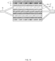
- The electrode assembly may be manufactured so that a positive electrode 1/a separator 3/a negative electrode 2 are stacked repeatedly. The electrode assembly is accommodated in a can such as a cylindrical can or a prismatic case. As illustrated in
FIG. 1A in which a side view of the electrode assembly is illustrated, the positive electrode 1 of the electrode assembly is coated with a positive electrodeactive material 1b on both surfaces of apositive electrode collector 1a, and the negative electrode 2 is coated with a negative electrodeactive material 2b on both surfaces of thenegative electrode collector 2a. Here, anegative electrode tab 2c and apositive electrode tab 1c (which are expanded in a state in which the active materials are not applied) protrude from thenegative electrode collector 2a and thepositive electrode collector 1a in the negative electrode 2 and the positive electrode 1 so that current flows through thenegative electrode tab 2c and thepositive electrode tab 1c, respectively. - As demands for secondary batteries increase in fields such as energy storage system (ESS) and electric vehicles, research and development are being conducted to increase in capacity of secondary batteries.
- As a result, a secondary battery using an NCM (nickel (Ni), cobalt (Co), and manganese (Mn))-based positive electrode material has been developed. However, the NCM-based secondary battery has a problem that, when a nickel content relatively increases, the capacity increases, but the thermal stability decreases, and thus, the possibility of ignition also increases.
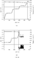
FIG. 1b is a graph illustrating a state in which the thermal stability varies depending on the nickel content.FIG. 1b(A) illustrates results of a thermal stability test of the electrode assembly coated with the positive electrode active material in which a composition ratio of nickel (Ni), cobalt (Co), and manganese (Mn) is 6:2:2, andFIG. 1b(B) illustrates results of a thermal stability test of the electrode assembly coated with the positive electrode active material in which a composition ratio of nickel (Ni), cobalt (Co), and manganese (Mn) is 8:1:1. The thermal stability test was performed by measuring a temperature change (a vertical axis) versus time (a horizontal axis) while heating is performed at a temperature of 80°C to 200°C at a rate of 2K/min. It is seen that both the electrode assemblies are ignited and damaged (at a point at which a cell voltage [Cell V] is zero; 460 minutes at which the cell voltage is zero inFIG. 1b(A) , and 280 minutes at which the cell voltage is zero inFIG. 1b(B) ), but the ignition more quickly occurs in the electrode assembly coated with the positive electrode active material having a composition ratio of 8:1:1 than the electrode assembly coated with the positive electrode active material having a composition ratio of 6:2:2. That is, it is seen that the thermal stability is deteriorated as the nickel content increases. - Accordingly, the present invention is to provide a secondary battery that is capable of using a positive electrode active material having a high nickel content so as to improve capacity as well as thermal stability.
- According to the present invention for achieving the above object, an electrode assembly in which a positive electrode, a separator, and a negative electrode are repeatedly stacked comprises: at least two or more positive electrodes which are stacked in the electrode assembly and each of which has a structure in which a positive electrode active material is applied to a surface of a positive electrode collector, wherein the positive electrode active material contains nickel, cobalt, and manganese, and a composition ratio of nickel, cobalt, and manganese in the positive electrode active material applied to one positive electrode is different from that of nickel, cobalt, and manganese in the positive electrode active material applied to the other positive electrode.
- According to the present invention, the positive electrode disposed at the relative outside in a stacking direction of the electrode assembly may be coated with a positive electrode active material containing a relatively small amount of manganese and a relative large amount of nickel, and the positive electrode disposed at the relative inside in the stacking direction of the electrode assembly may be coated with a positive electrode active material containing a relatively large amount of manganese and a relative small amount of nickel.
- According to Embodiment 1 of the present invention, the positive electrode disposed at the relative outside in the stacking direction of the electrode assembly may be coated with a positive electrode active material in which nickel, cobalt, and manganese are contained at a ratio of 8:1:1, and the positive electrode disposed at the relative inside in the stacking direction of the electrode assembly may be coated with a positive electrode active material in which nickel, cobalt, and manganese are contained at a ratio of 1:1:1.
- According to Embodiment 2 of the present invention, the positive electrode disposed at the relative outside in the stacking direction of the electrode assembly may be coated with a positive electrode active material in which nickel, cobalt, and manganese are contained at a ratio of 6:2:2, and the positive electrode disposed at the relative inside in the stacking direction of the electrode assembly may be coated with a positive electrode active material in which nickel, cobalt, and manganese are contained at a ratio of 1:1:1.
- According to Embodiment 3 of the present invention, the positive electrode disposed at the relative outside in the stacking direction of the electrode assembly may be coated with a positive electrode active material in which nickel, cobalt, and manganese are contained at a ratio of 8:1:1, and the positive electrode disposed at the relative inside in the stacking direction of the electrode assembly may be coated with a positive electrode active material in which nickel, cobalt, and manganese are contained at a ratio of 6:2:2.
- Also, the electrode assembly may have a structure in which three or more positive electrodes are stacked and comprise: one or more positive electrodes coated with a positive electrode active material in which nickel, cobalt, and manganese are contained at a ratio of 1:1:1; one or more positive electrodes coated with a positive electrode active material in which nickel, cobalt, and manganese are contained at a ratio of 6:2:2; and one or more positive electrodes coated with a positive electrode active material in which nickel, cobalt, and manganese are contained at a ratio of 8:1:1.
- A positive electrode tab of the positive electrode coated with the positive electrode active material containing a relatively small amount of manganese and a relatively large amount of nickel and a positive electrode tab of the positive electrode coated with the positive electrode active material containing a relatively large amount of manganese and a relatively small amount of nickel may be disposed to be separated from each other.
- A negative electrode tab disposed on the negative electrode in the electrode assembly may be disposed on one side, and the positive electrode tab is disposed on an opposite side, and the positive electrode tab of the positive electrode coated with the positive electrode active material containing the relatively small amount of manganese and the relatively large amount of nickel and the positive electrode tab of the positive electrode coated with the positive electrode active material containing the relatively large amount of manganese and the relatively small amount of nickel may be disposed to be spaced a predetermined distance from each other.
- The electrode assembly having the above-described technical feature may be embedded in a case to provide a secondary battery, and the secondary battery may be provided in plurality, which are electrically connected to each other to provide a secondary battery module.
- According to the present invention having the technical characteristics as described above, the positive electrodes, in which the positive electrode active material has the different composition ratios of nickel, cobalt, and manganese, may be stacked to adequately improve the thermal stability and the capacity.
- In more detail, the positive electrode active material containing a large amount of nickel to realize the high capacity may be disposed on the positive electrode disposed on the outside (the degradation may occur due to the relatively difficult heat dissipation), and the positive electrode active material containing a small amount of nickel to increase in thermal stability may be disposed on the positive electrode disposed on the inside to relatively improve the thermal stability and the capacity when compared to the case of using any kind of positive electrode.
- Furthermore, the positive electrode tab of the positive electrode coated with the positive electrode active material containing the relatively large amount of nickel and the positive electrode tab of the positive electrode coated with the positive electrode active material containing the relatively small amount of nickel may be disposed to be separated from each other to additionally reduce the electrical resistance (because the current flows to be divided).
-
-
FIG. 1a is a side view of an electrode assembly according to a related art. -
FIG. 1b is a graph illustrating a state in which thermal stability varies depending on a nickel content. -
FIG. 2a is a side view illustrating an electrode assembly according to a first embodiment of the present invention. -
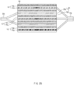
FIG. 2b is a side view illustrating an electrode assembly according to a second embodiment of the present invention. -
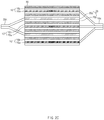
FIG. 2c is a side view illustrating an electrode assembly according to a third embodiment of the present invention. -
FIG. 3 is a plan view of an electrode assembly according to the present invention. - Hereinafter, preferred embodiments of the present invention will be described in detail with reference to the accompanying drawings in such a manner that the technical idea of the present invention may easily be carried out by a person with ordinary skill in the art to which the invention pertains. The present invention may, however, be embodied in different forms and should not be construed as limited to the embodiments set forth herein.
- In order to clearly illustrate the present invention, parts that are not related to the description are omitted, and the same or similar components are denoted by the same reference numerals throughout the specification.
- Also, terms or words used in this specification and claims should not be restrictively interpreted as ordinary meanings or dictionary-based meanings, but should be interpreted as meanings and concepts conforming to the scope of the present invention on the basis of the principle that an inventor can properly define the concept of a term to describe and explain his or her invention in the best ways.
- The present invention relates to an electrode assembly in which a positive electrode 10 (10', 10", and 10'''), a
separator 30, and anegative electrode 20 are repeatedly stacked. Here, at least two or morepositive electrodes 10 are stacked so that positive electrodeactive materials 10b applied to thepositive electrodes 10 have different composition ratios. - In more detail, in the present invention, the
positive electrode 10 is coated with the positive electrodeactive material 10b containing nickel, cobalt, and manganese. Here, a composition ratio of nickel, cobalt, and manganese in the positive electrodeactive material 10b applied to one positive electrode may be different from that of nickel, cobalt, and manganese in the positive electrodeactive material 10b applied to the other positive electrode. - Furthermore, according to the present invention, in order to improve thermal stability at an intermediate portion at which heat dissipation is difficult, the positive electrodes 10' and 10'" disposed at the relative outside in a stacking direction of the electrode assembly are coated with the positive electrode active material (a high Ni-based active material) containing a relatively small amount of manganese and a relative large amount of nickel, and the
positive electrode 10" disposed at the relative inside in the stacking direction of the electrode assembly is coated with the positive electrode active material (a low Ni-based active material) containing a relatively large amount of manganese and a relative small amount of nickel. Here, the amount of nickel is relatively determined. - Hereinafter, embodiments of the present invention will be described in detail with reference to the accompanying drawings.
- Referring to
FIG. 2a which illustrates a side view of an electrode assembly according to a first embodiment (for reference, although three positive electrodes are stacked inFIGS. 2a to 2c , three or more positive electrodes may be stacked), the electrode assembly according to this embodiment has a structure that is stacked downward in order ofseparator 30/positive electrode 10'/separator 30/negative electrode 20/separator 30/positive electrode 10"/separator 30/negative electrode 20/separator 30/positive electrode 10'". - The negative electrode has a structure in which a negative electrode active material 20b is applied to both surfaces of a
negative electrode collector 20a, and the positive electrode 10 (10', 10", and 10'") has a structure in which a positive electrodeactive material 10b is applied to both surfaces of apositive electrode collector 10a. The positive electrodeactive material 10b is manufactured by containing lithium, cobalt, and manganese. Here, the positive electrodes disposed at the relative outside in a stacking direction of the electrode assembly, i.e., the first positive electrode 10' and the third positive electrode 10'", which are disposed downward from an upper side may have a structure in which nickel, cobalt, and manganese are contained at a ratio of 8:1:1. On the other hand, the positive electrodeactive material 10b of thepositive electrode 10" disposed at the relative inside in the stacking direction of the electrode assembly has a structure in which nickel, cobalt, and manganese are contained at a ratio of 1:1:1. - Referring to
FIG. 2b which illustrates a side view of an electrode assembly according to a second embodiment, the electrode assembly according to this embodiment has a structure that is stacked downward in order ofseparator 30/positive electrode 10'/separator 30/negative electrode 20/separator 30/positive electrode 10"/separator 30/negative electrode 20/separator 30/positive electrode 10'". - Similarly, the positive electrode
active material 10b is manufactured by containing lithium, cobalt, and manganese. Here, the positive electrodes disposed at the relative outside in a stacking direction of the electrode assembly, i.e., the first positive electrode 10' and the third positive electrode 10'", which are disposed downward from an upper side may have a structure in which nickel, cobalt, and manganese are contained at a ratio of 8:1:1. On the other hand, the positive electrodeactive material 10b of thepositive electrode 10" disposed at the relative inside in the stacking direction of the electrode assembly has a structure in which nickel, cobalt, and manganese are contained at a ratio of 6:2:2. - The electrode assembly according to this embodiment has a configuration that focuses on increasing capacity rather than thermal stability because a nickel content of the electrode assembly according to this embodiment is slightly less than that of the electrode assembly according to the first embodiment.
- Referring to
FIG. 2c which illustrates a side view of an electrode assembly according to a third embodiment, the electrode assembly according to this embodiment has a structure that is stacked downward in order ofseparator 30/positive electrode 10'/separator 30/negative electrode 20/separator 30/positive electrode 10"/separator 30/negative electrode 20/separator 30/positive electrode 10'". - Similarly, the positive electrode
active material 10b is manufactured by containing lithium, cobalt, and manganese. Here, the positive electrodes disposed at the relatively outside in a stacking direction of the electrode assembly, i.e., the first positive electrode 10' and the third positive electrode 10'", which are disposed downward from an upper side may have a structure in which nickel, cobalt, and manganese are contained at a ratio of 6:2:2. On the other hand, the positive electrodeactive material 10b of thepositive electrode 10" disposed at the relatively inside in the stacking direction of the electrode assembly has a structure in which nickel, cobalt, and manganese are contained at a ratio of 1:1:1. - The electrode assembly according to this embodiment has a configuration that focuses on increasing thermal stability rather than capacity because a nickel content of the electrode assembly according to this embodiment is less than that of the electrode assembly according to each of the first and second embodiments.
- For reference, in the electrode assembly according to the present invention, three or more positive electrodes may be stacked. Thus, three kinds of positive electrodes having different compositions of nickel, cobalt, and manganese may be stacked.
- In this case, it is preferable that the positive electrode coated with the positive electrode active material having a low nickel content is disposed at the inside in which heat dissipation is relatively difficult, and the positive electrode coated with the positive electrode active material having a high nickel content is disposed at the outside in which the heat dissipation is relatively easy. For example, it is assumed that five positive electrodes are stacked downward from the upper side, positive electrodes coated with the positive electrode active material in which nickel, cobalt, and manganese are contained at a ratio of 8:1:1 may be respectively provided as first and fifth positive electrodes that are the outermost positive electrodes, positive electrodes coated with the positive electrode active material in which nickel, cobalt, and manganese are contained at a ratio of 6:2:2 may be provided as second and fourth positive electrodes, and a positive electrode coated with the positive electrode active material in which nickel, cobalt, and manganese are contained at a ratio of 1:1:1 may be provided as a third positive electrode (having relatively the lowest nickel content).
- In the electrode assembly configured as described above, it is preferable that the
positive electrodes 10 having the same composition ratio are electrically connected to each other. That is, since electrical conductivity of the positive electrodeactive material 10b are changed also as the composition ratio varies, it is preferable that the positive electrodes having different composition ratios are disposed to be separated from each other. When the positive electrode tabs are divided according to the composition ratios, current may flow to be divided. Thus, cell damage may be minimized to increase in lifespan of the battery. Also, the positive electrode having relatively high thermal stability may be charged by applying high current, and the positive electrode having relatively low thermal stability may be charged by applying low current. - Referring to
FIG. 3 , which illustrates a plan view of the electrode assembly according to the present invention, apositive electrode tab 10c' of a first positive electrode 10' and a positive electrode tab of a thirdpositive electrode 10a'", which have the same composition ratio, may be bonded and connected to each other. On the other hand, apositive electrode tab 10c" of the secondpositive electrode 10" and apositive electrode tab 10c' of the first positive electrode 10', which have different composition ratios, may be disposed to be spaced apart from each other. Here, since thenegative electrode tab 20c disposed on thenegative electrode 20 in the electrode assembly is disposed on one side, the positive electrode tabs are disposed at intervals on the same side of an opposite side. - According to the present invention having the technical characteristics as described above, the positive electrodes, in which the positive electrode
active material 10b has the different composition ratios of nickel, cobalt, and manganese, may be stacked to adequately improve the thermal stability and the capacity. - In more detail, the positive electrode active material containing a large amount of nickel to realize the high capacity may be disposed on the positive electrode disposed on the outside (the degradation may occur due to the relatively difficult heat dissipation), and the positive electrode active material containing a small amount of nickel to increase in thermal stability may be disposed on the positive electrode disposed on the inside to relatively improve the thermal stability and the capacity when compared to the case of using any kind of positive electrode.
- Furthermore, the positive electrode tab of the positive electrode coated with the positive electrode active material containing the relatively large amount of nickel and the positive electrode tab of the positive electrode coated with the positive electrode active material containing the relatively small amount of nickel may be disposed to be separated from each other to additionally reduce the electrical resistance (because the current flows to be divided).
- The electrode assembly having the above-described technical feature may be embedded in a case to provide a secondary battery, and a plurality of secondary batteries may be electrically connected to provide a secondary battery module.
- While the embodiments of the present invention have been described with reference to the specific embodiments, it will be apparent to those skilled in the art that various changes and modifications may be made without departing from the spirit and scope of the invention as defined in the following claims.
Claims (10)
- An electrode assembly in which a positive electrode, a separator, and a negative electrode are repeatedly stacked, the electrode assembly comprises:at least two or more positive electrodes which are stacked in the electrode assembly and each of which has a structure in which a positive electrode active material is applied to a surface of a positive electrode collector,wherein the positive electrode active material contains nickel, cobalt, and manganese, anda composition ratio of nickel, cobalt, and manganese in the positive electrode active material applied to one positive electrode is different from that of nickel, cobalt, and manganese in the positive electrode active material applied to the other positive electrode.
- The electrode assembly of claim 1, wherein the positive electrode disposed at the relative outside in a stacking direction of the electrode assembly is coated with a positive electrode active material containing a relatively small amount of manganese and a relative large amount of nickel, and
the positive electrode disposed at the relative inside in the stacking direction of the electrode assembly is coated with a positive electrode active material containing a relatively large amount of manganese and a relative small amount of nickel. - The electrode assembly of claim 2, wherein the positive electrode disposed at the relative outside in the stacking direction of the electrode assembly is coated with a positive electrode active material in which nickel, cobalt, and manganese are contained at a ratio of 8:1:1, and
the positive electrode disposed at the relative inside in the stacking direction of the electrode assembly is coated with a positive electrode active material in which nickel, cobalt, and manganese are contained at a ratio of 1:1:1. - The electrode assembly of claim 2, wherein the positive electrode disposed at the relative outside in the stacking direction of the electrode assembly is coated with a positive electrode active material in which nickel, cobalt, and manganese are contained at a ratio of 8:1:1, and
the positive electrode disposed at the relative inside in the stacking direction of the electrode assembly is coated with a positive electrode active material in which nickel, cobalt, and manganese are contained at a ratio of 6:2:2. - The electrode assembly of claim 2, wherein the positive electrode disposed at the relative outside in the stacking direction of the electrode assembly is coated with a positive electrode active material in which nickel, cobalt, and manganese are contained at a ratio of 6:2:2, and
the positive electrode disposed at the relative inside in the stacking direction of the electrode assembly is coated with a positive electrode active material in which nickel, cobalt, and manganese are contained at a ratio of 1:1:1. - The electrode assembly of claim 2, wherein the electrode assembly has a structure in which three or more positive electrodes are stacked and comprises: one or more positive electrodes coated with a positive electrode active material in which nickel, cobalt, and manganese are contained at a ratio of 1:1:1; one or more positive electrodes coated with a positive electrode active material in which nickel, cobalt, and manganese are contained at a ratio of 6:2:2; and one or more positive electrodes coated with a positive electrode active material in which nickel, cobalt, and manganese are contained at a ratio of 8:1:1.
- The electrode assembly of claim 2, wherein a positive electrode tab of the positive electrode coated with the positive electrode active material containing a relatively small amount of manganese and a relatively large amount of nickel and a positive electrode tab of the positive electrode coated with the positive electrode active material containing a relatively large amount of manganese and a relatively small amount of nickel are disposed to be separated from each other.
- The electrode assembly of claim 7, wherein a negative electrode tab disposed on the negative electrode in the electrode assembly is disposed on one side, and the positive electrode tab is disposed on an opposite side, and
the positive electrode tab of the positive electrode coated with the positive electrode active material containing the relatively small amount of manganese and the relatively large amount of nickel and the positive electrode tab of the positive electrode coated with the positive electrode active material containing the relatively large amount of manganese and the relatively small amount of nickel are disposed to be spaced a predetermined distance from each other. - A secondary battery in which the electrode assembly of any one of claims 1 to 8 is embedded in a case.
- A secondary battery module in which the secondary battery of claim 9 is provided in plurality, which are electrically connected to each other.
Applications Claiming Priority (2)
| Application Number | Priority Date | Filing Date | Title |
|---|---|---|---|
| KR1020180151259A KR102279002B1 (en) | 2018-11-29 | 2018-11-29 | Electrode Assembly |
| PCT/KR2019/012745 WO2020111490A1 (en) | 2018-11-29 | 2019-09-30 | Electrode assembly |
Publications (2)
| Publication Number | Publication Date |
|---|---|
| EP3713007A1 true EP3713007A1 (en) | 2020-09-23 |
| EP3713007A4 EP3713007A4 (en) | 2021-01-27 |
Family
ID=70853829
Family Applications (1)
| Application Number | Title | Priority Date | Filing Date |
|---|---|---|---|
| EP19891447.5A Pending EP3713007A4 (en) | 2018-11-29 | 2019-09-30 | ELECTRODE ASSEMBLY |
Country Status (6)
| Country | Link |
|---|---|
| US (1) | US11909040B2 (en) |
| EP (1) | EP3713007A4 (en) |
| JP (1) | JP7347413B2 (en) |
| KR (1) | KR102279002B1 (en) |
| CN (1) | CN111492526B (en) |
| WO (1) | WO2020111490A1 (en) |
Families Citing this family (3)
| Publication number | Priority date | Publication date | Assignee | Title |
|---|---|---|---|---|
| JP7349029B2 (en) * | 2021-05-20 | 2023-09-21 | 寧徳時代新能源科技股▲分▼有限公司 | Lithium ion secondary batteries, battery modules, battery packs and electrical devices |
| KR20230058870A (en) * | 2021-10-25 | 2023-05-03 | 주식회사 엘지에너지솔루션 | A lithium secondary battery having a fire suppression structure |
| WO2023221090A1 (en) * | 2022-05-20 | 2023-11-23 | 宁德时代新能源科技股份有限公司 | Battery cell, battery, and electric device |
Family Cites Families (27)
| Publication number | Priority date | Publication date | Assignee | Title |
|---|---|---|---|---|
| JP4693373B2 (en) * | 2004-07-21 | 2011-06-01 | 三洋電機株式会社 | Non-aqueous electrolyte battery |
| US20060240290A1 (en) | 2005-04-20 | 2006-10-26 | Holman Richard K | High rate pulsed battery |
| KR100894410B1 (en) | 2005-05-27 | 2009-04-24 | 주식회사 엘지화학 | Superposition Lithium Secondary Battery with Dissimilar Electrode Active Material Layer |
| KR100874387B1 (en) | 2006-06-13 | 2008-12-18 | 주식회사 엘지화학 | Overlapping secondary cells provide more than one operating voltage |
| CN101388449B (en) | 2008-10-31 | 2011-06-08 | 浙江南都电源动力股份有限公司 | Positive plate of high power lithium ionic cell and lithium ionic cell containing the same |
| MX2012002732A (en) | 2009-09-03 | 2012-10-09 | Molecular Nanosystems Inc | Methods and systems for making electrodes having at least one functional gradient therein and devices resulting therefrom. |
| KR101254691B1 (en) | 2010-08-17 | 2013-04-15 | 주식회사 엘지화학 | Secondary electric cell with enhanced lead structure |
| EP2500972B1 (en) | 2010-12-20 | 2017-07-26 | LG Chem, Ltd. | Lithium secondary battery having multi-directional lead-tab structure |
| JP5828754B2 (en) * | 2011-12-26 | 2015-12-09 | 株式会社日立製作所 | Positive electrode material and lithium ion secondary battery |
| JP2013187021A (en) | 2012-03-07 | 2013-09-19 | Nissan Motor Co Ltd | Secondary battery |
| KR20130139796A (en) | 2012-06-13 | 2013-12-23 | 주식회사 엘지화학 | Electrode assembly containing two type cathode and lithium secondary battery containing the same |
| JP2014071960A (en) * | 2012-09-27 | 2014-04-21 | Shin Kobe Electric Mach Co Ltd | Electrode plate group of secondary battery, and secondary battery |
| KR101990154B1 (en) | 2013-04-03 | 2019-06-17 | 에스케이이노베이션 주식회사 | Battery package assembled by battery cell having differential heat-resisting capacity |
| KR101805545B1 (en) | 2013-11-11 | 2017-12-07 | 삼성에스디아이 주식회사 | Electrode assembly and secondary battery using the electrode assembly |
| CN106463780B (en) * | 2014-06-24 | 2019-05-31 | 株式会社钟化 | Non-aqueous electrolyte secondary battery, and assembled battery formed by connecting a plurality of the non-aqueous electrolyte secondary batteries |
| KR101690497B1 (en) | 2014-07-24 | 2016-12-28 | 에스케이이노베이션 주식회사 | Secondary Battery and the Design Method Thereof |
| CN104393282A (en) * | 2014-12-20 | 2015-03-04 | 宫香娥 | Preparation method of multi-element cathode material coated by graphene |
| CN104852043A (en) * | 2014-12-31 | 2015-08-19 | 常州益辉新能源科技有限公司 | High voltage anode material for lithium ion battery and preparation method thereof |
| JP2016178051A (en) | 2015-03-23 | 2016-10-06 | 株式会社日立製作所 | Lithium ion secondary battery |
| KR102490865B1 (en) | 2015-06-18 | 2023-01-20 | 삼성에스디아이 주식회사 | Electrode assembly and lithium battery including the same |
| CN106328925A (en) * | 2015-06-30 | 2017-01-11 | 宁德时代新能源科技股份有限公司 | Lithium ion secondary battery and positive pole piece thereof |
| WO2017042655A1 (en) | 2015-09-08 | 2017-03-16 | Umicore | PRECURSOR AND METHOD FOR PREPARING Li TRANSITION METAL OXIDE CATHODES FOR RECHARGEABLE BATTERIES |
| JP6264429B2 (en) * | 2016-11-07 | 2018-01-24 | 株式会社村田製作所 | Batteries, battery packs, electronic devices, electric vehicles, power storage devices, and power systems |
| JP6932723B2 (en) | 2016-12-28 | 2021-09-08 | パナソニック株式会社 | Non-aqueous electrolyte secondary battery |
| JP2018174070A (en) | 2017-03-31 | 2018-11-08 | Tdk株式会社 | Lithium ion secondary battery |
| CN106981652A (en) | 2017-04-17 | 2017-07-25 | 张保平 | A kind of template preparation method of ternary cathode material of lithium ion battery |
| CN108155362A (en) * | 2017-12-25 | 2018-06-12 | 北京国能电池科技有限公司 | High-voltage lithium-battery cathode material, lithium ion battery and preparation method thereof |
-
2018
- 2018-11-29 KR KR1020180151259A patent/KR102279002B1/en active Active
-
2019
- 2019-09-30 US US16/963,081 patent/US11909040B2/en active Active
- 2019-09-30 JP JP2020516563A patent/JP7347413B2/en active Active
- 2019-09-30 WO PCT/KR2019/012745 patent/WO2020111490A1/en not_active Ceased
- 2019-09-30 EP EP19891447.5A patent/EP3713007A4/en active Pending
- 2019-09-30 CN CN201980006412.7A patent/CN111492526B/en active Active
Also Published As
| Publication number | Publication date |
|---|---|
| CN111492526B (en) | 2023-07-25 |
| JP7347413B2 (en) | 2023-09-20 |
| US20200350583A1 (en) | 2020-11-05 |
| JP2021509997A (en) | 2021-04-08 |
| KR102279002B1 (en) | 2021-07-20 |
| KR20200064753A (en) | 2020-06-08 |
| WO2020111490A1 (en) | 2020-06-04 |
| EP3713007A4 (en) | 2021-01-27 |
| CN111492526A (en) | 2020-08-04 |
| US11909040B2 (en) | 2024-02-20 |
Similar Documents
| Publication | Publication Date | Title |
|---|---|---|
| US8263266B2 (en) | Electrode assembly and secondary battery having the same | |
| CN101141009B (en) | Assembled battery | |
| CN103477490B (en) | Rolled electrode assembly pattern-coated with active material and secondary battery including same | |
| US10020506B2 (en) | Active material for a cathode of a battery cell, cathode, and battery cell | |
| CN102473969B (en) | Method of charging non-aqueous electrolyte secondary battery, and battery pack | |
| KR100289537B1 (en) | lithum secondary battery | |
| US20170373339A1 (en) | Secondary battery and cylindrical lithium secondary battery | |
| JP3799463B2 (en) | Battery module | |
| EP4270565A1 (en) | Electrode assembly and secondary battery comprising same | |
| CN105990598B (en) | Electric storage element | |
| KR102734115B1 (en) | A positive electrode and an electrode assembly comprising the positive electrode | |
| EP3771018B1 (en) | Electrode assembly | |
| US11909040B2 (en) | Electrode assembly | |
| JP5292260B2 (en) | Non-aqueous secondary battery and battery module | |
| US10727526B2 (en) | Secondary battery | |
| KR101935229B1 (en) | Lithium secondary battery | |
| KR101431726B1 (en) | Electrode Assembly of Improved Safety And Secondary Battery with the Same | |
| US9553302B2 (en) | Electrode assemblage and rechargeable battery using the same | |
| US11450906B2 (en) | Secondary cylindrical battery having piezoelectric element and thermoelectric element | |
| EP3780237A1 (en) | Unit cell and manufacturing method therefor | |
| KR20150083633A (en) | Jelly-roll electrode assembly and lithium secondary battery including the same | |
| KR20150083634A (en) | Jelly-roll electrode assembly and lithium secondary battery including the same | |
| US10811732B1 (en) | Pre-lithiation for batteries having si-anodes | |
| US20200176781A1 (en) | Rechargeable battery | |
| JP2016178027A (en) | Power storage device and manufacturing method thereof |
Legal Events
| Date | Code | Title | Description |
|---|---|---|---|
| STAA | Information on the status of an ep patent application or granted ep patent |
Free format text: STATUS: THE INTERNATIONAL PUBLICATION HAS BEEN MADE |
|
| PUAI | Public reference made under article 153(3) epc to a published international application that has entered the european phase |
Free format text: ORIGINAL CODE: 0009012 |
|
| STAA | Information on the status of an ep patent application or granted ep patent |
Free format text: STATUS: REQUEST FOR EXAMINATION WAS MADE |
|
| 17P | Request for examination filed |
Effective date: 20200617 |
|
| AK | Designated contracting states |
Kind code of ref document: A1 Designated state(s): AL AT BE BG CH CY CZ DE DK EE ES FI FR GB GR HR HU IE IS IT LI LT LU LV MC MK MT NL NO PL PT RO RS SE SI SK SM TR |
|
| AX | Request for extension of the european patent |
Extension state: BA ME |
|
| A4 | Supplementary search report drawn up and despatched |
Effective date: 20210113 |
|
| RIC1 | Information provided on ipc code assigned before grant |
Ipc: H01M 4/131 20100101ALI20201222BHEP Ipc: H01M 4/505 20100101ALI20201222BHEP Ipc: H01M 2/26 20060101ALI20201222BHEP Ipc: H01M 4/525 20100101ALI20201222BHEP Ipc: H01M 10/052 20100101ALI20201222BHEP Ipc: H01M 10/0585 20100101AFI20201222BHEP |
|
| RAP1 | Party data changed (applicant data changed or rights of an application transferred) |
Owner name: LG ENERGY SOLUTION LTD. |
|
| DAV | Request for validation of the european patent (deleted) | ||
| DAX | Request for extension of the european patent (deleted) | ||
| RAP3 | Party data changed (applicant data changed or rights of an application transferred) |
Owner name: LG ENERGY SOLUTION, LTD. |