EP3712869B1 - Smart child safety device in vehicles - Google Patents
Smart child safety device in vehicles Download PDFInfo
- Publication number
- EP3712869B1 EP3712869B1 EP20164120.6A EP20164120A EP3712869B1 EP 3712869 B1 EP3712869 B1 EP 3712869B1 EP 20164120 A EP20164120 A EP 20164120A EP 3712869 B1 EP3712869 B1 EP 3712869B1
- Authority
- EP
- European Patent Office
- Prior art keywords
- sensor
- vehicle
- door
- child safety
- event
- Prior art date
- Legal status (The legal status is an assumption and is not a legal conclusion. Google has not performed a legal analysis and makes no representation as to the accuracy of the status listed.)
- Active
Links
Images



Classifications
-
- G—PHYSICS
- G08—SIGNALLING
- G08B—SIGNALLING SYSTEMS, e.g. PERSONAL CALLING SYSTEMS; ORDER TELEGRAPHS; ALARM SYSTEMS
- G08B21/00—Alarms responsive to a single specified undesired or abnormal condition and not otherwise provided for
- G08B21/18—Status alarms
- G08B21/22—Status alarms responsive to presence or absence of persons
-
- B—PERFORMING OPERATIONS; TRANSPORTING
- B60—VEHICLES IN GENERAL
- B60R—VEHICLES, VEHICLE FITTINGS, OR VEHICLE PARTS, NOT OTHERWISE PROVIDED FOR
- B60R21/00—Arrangements or fittings on vehicles for protecting or preventing injuries to occupants or pedestrians in case of accidents or other traffic risks
- B60R21/01—Electrical circuits for triggering passive safety arrangements, e.g. airbags, safety belt tighteners, in case of vehicle accidents or impending vehicle accidents
- B60R21/015—Electrical circuits for triggering passive safety arrangements, e.g. airbags, safety belt tighteners, in case of vehicle accidents or impending vehicle accidents including means for detecting the presence or position of passengers, passenger seats or child seats, and the related safety parameters therefor, e.g. speed or timing of airbag inflation in relation to occupant position or seat belt use
- B60R21/01556—Child-seat detection systems
-
- B—PERFORMING OPERATIONS; TRANSPORTING
- B60—VEHICLES IN GENERAL
- B60N—SEATS SPECIALLY ADAPTED FOR VEHICLES; VEHICLE PASSENGER ACCOMMODATION NOT OTHERWISE PROVIDED FOR
- B60N2/00—Seats specially adapted for vehicles; Arrangement or mounting of seats in vehicles
- B60N2/24—Seats specially adapted for vehicles; Arrangement or mounting of seats in vehicles for particular purposes or particular vehicles
- B60N2/26—Seats specially adapted for vehicles; Arrangement or mounting of seats in vehicles for particular purposes or particular vehicles for children
- B60N2/266—Seats specially adapted for vehicles; Arrangement or mounting of seats in vehicles for particular purposes or particular vehicles for children with detection or alerting means responsive to presence or absence of children; with detection or alerting means responsive to improper locking or installation of the child seats or parts thereof
- B60N2/267—Seats specially adapted for vehicles; Arrangement or mounting of seats in vehicles for particular purposes or particular vehicles for children with detection or alerting means responsive to presence or absence of children; with detection or alerting means responsive to improper locking or installation of the child seats or parts thereof alerting means responsive to presence or absence of children
-
- B—PERFORMING OPERATIONS; TRANSPORTING
- B60—VEHICLES IN GENERAL
- B60N—SEATS SPECIALLY ADAPTED FOR VEHICLES; VEHICLE PASSENGER ACCOMMODATION NOT OTHERWISE PROVIDED FOR
- B60N2/00—Seats specially adapted for vehicles; Arrangement or mounting of seats in vehicles
- B60N2/24—Seats specially adapted for vehicles; Arrangement or mounting of seats in vehicles for particular purposes or particular vehicles
- B60N2/26—Seats specially adapted for vehicles; Arrangement or mounting of seats in vehicles for particular purposes or particular vehicles for children
- B60N2/266—Seats specially adapted for vehicles; Arrangement or mounting of seats in vehicles for particular purposes or particular vehicles for children with detection or alerting means responsive to presence or absence of children; with detection or alerting means responsive to improper locking or installation of the child seats or parts thereof
- B60N2/271—Seats specially adapted for vehicles; Arrangement or mounting of seats in vehicles for particular purposes or particular vehicles for children with detection or alerting means responsive to presence or absence of children; with detection or alerting means responsive to improper locking or installation of the child seats or parts thereof detecting or alerting means responsive to securing the child in the seat
-
- B—PERFORMING OPERATIONS; TRANSPORTING
- B60—VEHICLES IN GENERAL
- B60N—SEATS SPECIALLY ADAPTED FOR VEHICLES; VEHICLE PASSENGER ACCOMMODATION NOT OTHERWISE PROVIDED FOR
- B60N2/00—Seats specially adapted for vehicles; Arrangement or mounting of seats in vehicles
- B60N2/24—Seats specially adapted for vehicles; Arrangement or mounting of seats in vehicles for particular purposes or particular vehicles
- B60N2/26—Seats specially adapted for vehicles; Arrangement or mounting of seats in vehicles for particular purposes or particular vehicles for children
- B60N2/274—Seats specially adapted for vehicles; Arrangement or mounting of seats in vehicles for particular purposes or particular vehicles for children characterised by the communication means between the child seat and another entity, e.g. vehicle or portable device
-
- B—PERFORMING OPERATIONS; TRANSPORTING
- B60—VEHICLES IN GENERAL
- B60N—SEATS SPECIALLY ADAPTED FOR VEHICLES; VEHICLE PASSENGER ACCOMMODATION NOT OTHERWISE PROVIDED FOR
- B60N2/00—Seats specially adapted for vehicles; Arrangement or mounting of seats in vehicles
- B60N2/24—Seats specially adapted for vehicles; Arrangement or mounting of seats in vehicles for particular purposes or particular vehicles
- B60N2/26—Seats specially adapted for vehicles; Arrangement or mounting of seats in vehicles for particular purposes or particular vehicles for children
- B60N2/28—Seats readily mountable on, and dismountable from, existing seats or other parts of the vehicle
-
- B—PERFORMING OPERATIONS; TRANSPORTING
- B60—VEHICLES IN GENERAL
- B60R—VEHICLES, VEHICLE FITTINGS, OR VEHICLE PARTS, NOT OTHERWISE PROVIDED FOR
- B60R21/00—Arrangements or fittings on vehicles for protecting or preventing injuries to occupants or pedestrians in case of accidents or other traffic risks
- B60R21/01—Electrical circuits for triggering passive safety arrangements, e.g. airbags, safety belt tighteners, in case of vehicle accidents or impending vehicle accidents
-
- B—PERFORMING OPERATIONS; TRANSPORTING
- B60—VEHICLES IN GENERAL
- B60R—VEHICLES, VEHICLE FITTINGS, OR VEHICLE PARTS, NOT OTHERWISE PROVIDED FOR
- B60R21/00—Arrangements or fittings on vehicles for protecting or preventing injuries to occupants or pedestrians in case of accidents or other traffic risks
- B60R21/01—Electrical circuits for triggering passive safety arrangements, e.g. airbags, safety belt tighteners, in case of vehicle accidents or impending vehicle accidents
- B60R21/015—Electrical circuits for triggering passive safety arrangements, e.g. airbags, safety belt tighteners, in case of vehicle accidents or impending vehicle accidents including means for detecting the presence or position of passengers, passenger seats or child seats, and the related safety parameters therefor, e.g. speed or timing of airbag inflation in relation to occupant position or seat belt use
- B60R21/01512—Passenger detection systems
- B60R21/01516—Passenger detection systems using force or pressure sensing means
-
- B—PERFORMING OPERATIONS; TRANSPORTING
- B60—VEHICLES IN GENERAL
- B60R—VEHICLES, VEHICLE FITTINGS, OR VEHICLE PARTS, NOT OTHERWISE PROVIDED FOR
- B60R21/00—Arrangements or fittings on vehicles for protecting or preventing injuries to occupants or pedestrians in case of accidents or other traffic risks
- B60R21/01—Electrical circuits for triggering passive safety arrangements, e.g. airbags, safety belt tighteners, in case of vehicle accidents or impending vehicle accidents
- B60R21/015—Electrical circuits for triggering passive safety arrangements, e.g. airbags, safety belt tighteners, in case of vehicle accidents or impending vehicle accidents including means for detecting the presence or position of passengers, passenger seats or child seats, and the related safety parameters therefor, e.g. speed or timing of airbag inflation in relation to occupant position or seat belt use
- B60R21/01512—Passenger detection systems
- B60R21/01544—Passenger detection systems detecting seat belt parameters, e.g. length, tension or height-adjustment
- B60R21/01546—Passenger detection systems detecting seat belt parameters, e.g. length, tension or height-adjustment using belt buckle sensors
-
- B—PERFORMING OPERATIONS; TRANSPORTING
- B60—VEHICLES IN GENERAL
- B60R—VEHICLES, VEHICLE FITTINGS, OR VEHICLE PARTS, NOT OTHERWISE PROVIDED FOR
- B60R25/00—Fittings or systems for preventing or indicating unauthorised use or theft of vehicles
- B60R25/30—Detection related to theft or to other events relevant to anti-theft systems
- B60R25/32—Detection related to theft or to other events relevant to anti-theft systems of vehicle dynamic parameters, e.g. speed or acceleration
-
- B—PERFORMING OPERATIONS; TRANSPORTING
- B60—VEHICLES IN GENERAL
- B60R—VEHICLES, VEHICLE FITTINGS, OR VEHICLE PARTS, NOT OTHERWISE PROVIDED FOR
- B60R25/00—Fittings or systems for preventing or indicating unauthorised use or theft of vehicles
- B60R25/30—Detection related to theft or to other events relevant to anti-theft systems
- B60R25/34—Detection related to theft or to other events relevant to anti-theft systems of conditions of vehicle components, e.g. of windows, door locks or gear selectors
-
- G—PHYSICS
- G08—SIGNALLING
- G08B—SIGNALLING SYSTEMS, e.g. PERSONAL CALLING SYSTEMS; ORDER TELEGRAPHS; ALARM SYSTEMS
- G08B21/00—Alarms responsive to a single specified undesired or abnormal condition and not otherwise provided for
- G08B21/18—Status alarms
- G08B21/24—Reminder alarms, e.g. anti-loss alarms
-
- B—PERFORMING OPERATIONS; TRANSPORTING
- B60—VEHICLES IN GENERAL
- B60N—SEATS SPECIALLY ADAPTED FOR VEHICLES; VEHICLE PASSENGER ACCOMMODATION NOT OTHERWISE PROVIDED FOR
- B60N2/00—Seats specially adapted for vehicles; Arrangement or mounting of seats in vehicles
- B60N2/002—Seats provided with an occupancy detection means mounted therein or thereon
- B60N2/0021—Seats provided with an occupancy detection means mounted therein or thereon characterised by the type of sensor or measurement
- B60N2/0035—Seats provided with an occupancy detection means mounted therein or thereon characterised by the type of sensor or measurement characterised by the sensor data transmission, e.g. wired connections or wireless transmitters therefor; characterised by the sensor data processing, e.g. seat sensor signal amplification or electric circuits for providing seat sensor information
-
- B—PERFORMING OPERATIONS; TRANSPORTING
- B60—VEHICLES IN GENERAL
- B60N—SEATS SPECIALLY ADAPTED FOR VEHICLES; VEHICLE PASSENGER ACCOMMODATION NOT OTHERWISE PROVIDED FOR
- B60N2210/00—Sensor types, e.g. for passenger detection systems or for controlling seats
- B60N2210/10—Field detection presence sensors
- B60N2210/14—Inductive; Magnetic field
-
- B—PERFORMING OPERATIONS; TRANSPORTING
- B60—VEHICLES IN GENERAL
- B60N—SEATS SPECIALLY ADAPTED FOR VEHICLES; VEHICLE PASSENGER ACCOMMODATION NOT OTHERWISE PROVIDED FOR
- B60N2210/00—Sensor types, e.g. for passenger detection systems or for controlling seats
- B60N2210/40—Force or pressure sensors
-
- B—PERFORMING OPERATIONS; TRANSPORTING
- B60—VEHICLES IN GENERAL
- B60N—SEATS SPECIALLY ADAPTED FOR VEHICLES; VEHICLE PASSENGER ACCOMMODATION NOT OTHERWISE PROVIDED FOR
- B60N2210/00—Sensor types, e.g. for passenger detection systems or for controlling seats
- B60N2210/50—Inertial sensors
-
- B—PERFORMING OPERATIONS; TRANSPORTING
- B60—VEHICLES IN GENERAL
- B60N—SEATS SPECIALLY ADAPTED FOR VEHICLES; VEHICLE PASSENGER ACCOMMODATION NOT OTHERWISE PROVIDED FOR
- B60N2220/00—Computerised treatment of data for controlling of seats
- B60N2220/30—Computerised treatment of data for controlling of seats using a neural network
-
- B—PERFORMING OPERATIONS; TRANSPORTING
- B60—VEHICLES IN GENERAL
- B60N—SEATS SPECIALLY ADAPTED FOR VEHICLES; VEHICLE PASSENGER ACCOMMODATION NOT OTHERWISE PROVIDED FOR
- B60N2230/00—Communication or electronic aspects
- B60N2230/20—Wireless data transmission
-
- B—PERFORMING OPERATIONS; TRANSPORTING
- B60—VEHICLES IN GENERAL
- B60N—SEATS SPECIALLY ADAPTED FOR VEHICLES; VEHICLE PASSENGER ACCOMMODATION NOT OTHERWISE PROVIDED FOR
- B60N2230/00—Communication or electronic aspects
- B60N2230/30—Signal processing of sensor data
Definitions
- the present disclosure relates generally to sensors integrated in a smart device, and more particularly, to smart child safety devices having sensors.
- the mobile device may also include multiple micro-electromechanical sensors (MEMS) that can enable the determination of various types of contextual information of the device's user.
- MEMS micro-electromechanical sensors
- Some of the sensors useful for obtaining contextual information are accelerometers, air pressure sensors, gyroscopes, magnetometers and microphones.
- WO 2012/109472 discloses a system for indicating the presence of a child in a vehicle, wherein the system generates an alarm after determining that a child is in the seat and the vehicle is not in motion.
- US 2018/0111597 discloses a rear cargo reminder system having a front door sensor and a rear door sensor, an alerting device and a controller.
- the controller operates the alerting device based on the sequence of opening of the vehicle doors.
- the aim of the invention is to overcome prior art limitations and problems, in particular for determining an awareness scenario related to a child safety device using smart sensors separately from the vehicle.
- the present invention provides a smart safety system and method, as defined in the appended claims.
- a smart sensor refers to a sensor that includes or is coupled to a processing capacity capable of conducting one or more of processing the detected information or communicating the detected information to a remote processing unit.
- An awareness scenario is a scenario related to one or more of the operation of the vehicle or the use of the child safety device which a user likes to be aware of. For example, an example awareness scenario includes that a user leaves a parked vehicle with a child still secured in a child safety seat in the vehicle. Another example awareness scenario includes that a backseat door of a vehicle adjacent to a child safety seat is opened when the vehicle is moving.
- a child safety seat includes a vehicle motion sensor, e.g., an accelerometer, and a door motion sensor such as a pressure sensor, e.g., an air pressure sensor.
- vehicle motion sensor is configured to detect a motion state of a vehicle where the child safety seat is installed, e.g., whether the vehicle is moving or non-moving.
- the door motion sensor e.g. pressure sensor, is configured to detect a motion state of a door of the vehicle, e.g., a door open/close motion. Based on the information detected by the vehicle motion sensor and the door motion sensor, a controller determines whether an awareness scenario occurs.
- the controller may determine that a driver leaves the vehicle. If the controller also determines that a child is still in the child safety seat, either through sensing or through human inputs, the controller will generate a control event, e.g., by initiating an alarm, which reminds a user of the awareness scenario, e.g., a child is left in the unattended vehicle.
- the controller may be physically integrated with the vehicle motion sensor and the door motion sensor on the child safety seat or may reside on a separate smart device and communicate with one or more of the vehicle motion sensor or the door motion sensor through wired or wireless communication. To this extent, the controller may be positioned within or adjacent to the vehicle or may be positioned remotely to the vehicle.
- the alarm may be generated by one or more of a microphone device coupled together with the vehicle motion sensor or the door motion sensor on the child safety seat or a microphone device coupled to the controller.
- the controller includes an artificial intelligence unit that can be trained to identify a door opening/closing event as differentiated from a window opening/closing event or a roof opening/closing event.
- the artificial intelligence unit may individualize the determination function of the controller with respect to one or more of individual vehicle or individual drivers of the vehicles. For example, the artificial intelligence unit may be trained to delay an individualized grace period of time between detecting an awareness scenario and activating an alarm. The individualized grace period of time may be trained based on historical date of the driver completing a series of actions of opening driver side door, closing driver side door, walking to the rear seat door and opening the rear seat door to release a child from the child safety seat. Other trainings of the controller are also possible and included in the disclosure.
- the controller evaluates the readings of the vehicle motion sensor and the door motion sensor based on the sequential order of the readings one or more of before or after a piece of targeted event. For example, the readings before and after a targeted event are evaluated to identify whether the targeted event corresponds to an awareness scenario.
- Fig. 1 illustrates an example system 100 for determining an awareness scenario in relation to a child safety device installed in a vehicle.
- the system 100 includes a sensor suite 110 and a smart device 130.
- Sensor suite 110 may be integrated onto the smart device 130 and/or may be communicatively and/or electrically coupled to the smart device 130.
- the sensor suite 110 may include one or more platforms (here, one platform 112) and various sensors contained in or attached onto the platform 112 for detecting various context data.
- the various sensors include here, but are not limited to, one or more motion sensors, shown as an accelerometer 114, a first pressure sensor 116, e.g., an air pressure sensor, a second pressure sensor 118, e.g., a load sensor, a magnetometer 120, a proximity sensor 122, a satellite based positioning sensor (e.g., a GPS sensor) 124, an environmental sensor 126 (e.g., a gas sensor and/or a humidity sensor), a microphone 128 and other sensors.
- the sensors of the sensor suite 110 may be one or more of coupled or integrated onto the child safety device, coupled to integrated onto the vehicle or coupled to integrated to the smart device 130.
- the sensors in the sensor suite 110 may be attached to one another or be separate from one another.
- one or more sensors in the sensor suite 110 may include or be coupled to an embedded processing unit that is configured to one or more of process the readings of the sensors or to communicate the readings of the sensor to the smart device 130.
- the accelerometer 114 and the first pressure sensor 116 may be contained in the platform 112 and attached to the body of the child safety seat 202
- the smart device 130 includes a processing unit 132, e.g., a general or special purpose processor or a micro controller (MCU), and a storage device134, e.g., a memory.
- the memory 134 may store computer executable instructions which, when executed by the processing unit 132, configure the processing unit 132 to implement a context awareness module 136 and a device configuration module 138.
- the device configuration module 138 is an artificial intelligence unit that is operable to learn and train one or more of the context awareness module 136 or the sensor suite 110 based on historical data of context awareness detections and determinations and other data related to the context awareness detections and determinations. The training may be conducted continuously with each context awareness detection data and determination data being used to update the dataset for the training purposes.
- the memory 134 may store a classification parameter library 140, which is a database of classification parameters for classifying a sensor reading detected by a sensor in the sensor suite 110. The classification parameters may be trained and/or adjusted by the device configuration module 138.
- the smart device 130 of Fig. 1 also includes a display unit 150, an interfacing unit 160, a radio frequency (RF) unit 170 and other components 180.
- the display unit 150 is configured to display information through a display device, e.g., an active matrix organic light emitting device ("AMOLED").
- the interfacing unit 160 is configured to enable a user to interface with the smart device 130 through a user interface device, e.g., a keyboard, a touch screen, or a gesture recognition device.
- the RF unit 170 is configured to receive or transmit radio frequency signals for the smart device 130 to communicate with other devices, e.g., another smart device 130.
- the components of the device 130 may reside in a single physical computing device or reside in multiple computing devices that function together in a distributed computing environment to implement the smart device 130.
- the smart device 130 may be coupled to or integrated with the sensor suite 110 or may be communicatively linked to the sensor suite 110. Further, in the situation that the functions and components of the smart device 130 are implemented by multiple computing devices 130, the multiple computing devices 130 may be adjacent to the sensor suite 110 or may be distal from the sensor suite 130 or in various combinations of being adjacent to or distal from the sensor suite 110 among the multiple computing devices 130.
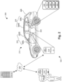
- Fig. 2 illustrates an operation environment 200 for context awareness analysis.
- system 100 is coupled to a child safety device 202 within a context 210.
- the context 210 includes a user 212 and a vehicle 220.
- the vehicle 220 includes two front seat doors 222 and in some models, backseat doors 224.
- the front seat doors 222 include a driver side door 222L, shown as the left front door, and a passenger side door 222R.
- the backseat doors 224 include a left-side backseat door 224L and a right-side backseat door 224R.
- the child safety device 202 e.g., a child safety seat, is installed in the backseat of the vehicle 220, closer to the backseat doors 224, if any, than to the front seat doors 222.
- a car is used as an illustrative example of a vehicle 220, which is not limiting.
- the vehicle 220 may be any type of transportation machine with which a child safety device 202 is used, which are all included in the disclosure.
- the sensor suite 110 includes a motion sensor, e.g., the accelerometer 114, and the first pressure sensor 116, e.g., an air pressure sensor, that are attached to the child safety seat 202.
- the motion sensor 114 can be configured to detect a motion state of the vehicle 220.
- the first pressure sensor 116 is designed to detect an air pressure change thereabout.
- the first pressure sensor 116 can be configured to detect a motion of a vehicle door 222, 224 as the opening or closing the car door causes the air pressure within the vehicle 220 to change.
- the readings of the first pressure sensor 116 may be fine-tuned to differentiate between the front door 222 motion and the backseat door 224 motion.
- the accelerometer 114 and the first pressure sensor 116 may be contained in the platform 112 and attached to the child safety seat 202.
- the accelerometer 114 and the first pressure sensor 116 may be contained in different platforms 112 and are attached to different parts of one or more of the child safety seat 202 or the vehicle 220.
- the first pressure 116 may be attached to a door 222, 224 of the vehicle 220.
- the sensor suite 110 may also include the second pressure sensor 118 configured as a weight/load sensor and positioned on or below a seat area of the child safety seat 202.
- the second pressure sensor 118 can be configured to detect whether a load, e.g., a child, is positioned on the seat area of the child safety seat 202.
- the sensor suite 110 may also include the magnetometer 120 attached adjacent to harness buckles of the child safety seat 202.
- the magnetometer 120 may be configured to detect whether the harness buckles are engaged or disengaged.
- the second pressure sensor 118 and/or the magnetometer 120 are configured to detect whether a child is positioned in the child safety seat 202.
- the sensor suite 110 may include other sensors that are configured to detect information about the context 210, e.g., the audio/sound information, the location information, or other information about the context 210, which are generally reference to as "context information”.
- information about the context 210 e.g., the audio/sound information, the location information, or other information about the context 210, which are generally reference to as "context information”.
- the sensor suite 110 may be coupled to a first smart device 130(1) with limited computation capacity to enable a transmittance of the detected context data to a device of higher computation capacity, e.g., a more capable second smart device 130(2) or a computer, such as a server 130(3) .
- the data links between the sensor suite 110, the first smart device 130(1), the second smart device 130(2) and the server 130(3) are provided for illustrative purposes, which does not limit the scope of the disclosure.
- the devices 130(1), 130(2), 130(3) and the sensor suite 110 may communicate with one another through a communication network 230, e.g., a wireless communication network.
- a communication network 230 e.g., a wireless communication network.
- the smart device 130(1), 130(2), the server 130(3) and the respective components thereof may function separately or in combination to achieve context awareness.
- the sensors of the sensor suite 110 are used to detect context information of the context 210. It should be appreciated that sensors of the sensor suite1 10 may reside on or be coupled to different smart devices 130(1), 130(2) which may be communicatively coupled to one another directly through network 230 or indirectly through the server 130(3).
- the data processing of the context information detected by sensors of the sensor suite 110 may be locally processed by the respective associated smart devices 130(1), 130(2) or may be centrally processed by the server 130(3).
- the processing of detected context information may be distributed among multiple smart devices 130(1), 130(2) and the server 130(3) such that the computation capacity, efficiency and timeliness in the data processing can be optimally balanced.
- the detected context information may be pre-processed locally on the smart device(s) 130(1), 130(2) and then processed centrally on the server 130(3).
- the detected context data is first locally pre-processed at respective first smart devices 130(1) and then collected by another one of the first smart devices 130(1), e.g., as a local processing hub, to process context awareness by itself or together with the server 130(3).
- the server 130(3) functioning as a cloud-based processing unit working with multiple smart devices 130(1), 130(2) is used as an illustrative example to describe the disclosed techniques.
- the server 130(3) is also referred to as a remote device 130(3) and the first smart device(s) 130(1) are also referred to as local device(s) 130(1).
- this illustrative example is not meant to limit the scope of the disclosure. Variants to this example are possible and appreciated as within the principles of the disclosure.
- the local device(s) 130(1) may be attached to the child safety seat 202 together with at least part of the sensor suite 110, or may be installed on a mobile device, e.g., a smart phone, that is portable with the user 212, or may be coupled to a portion of the vehicle 220.
- a mobile device e.g., a smart phone
- Fig. 3 illustrates an example local device 130(1) having a context awareness module 336.
- local context awareness module 336 may include a sensor input receiving unit 340, a data pre-processing unit 350 that includes a data harmonizing unit 352 and a feature extraction unit 354, a target event determination unit 360 that includes a local classification parameter library 362, an awareness scenario determination unit 370, a control event generation unit 380, and an operation controller 390.
- the local context awareness module 336 and the components thereof may each be implemented as hardware, software or a combination of hardware and software, which are all included in the disclosure.
- sensor input receiving unit 340 may be configured to receive raw context data detected by sensors of the sensor suite 110.
- the receiving may be implemented through data bus or through various near-field or long-range data communication networks like blue-tooth, NFC, cellular-based mobile data communication, or other data communication approaches.
- Data pre-processing unit 350 may be configured to pre-process the received raw context data to facilitate further processing.
- the pre-processing may include filtering the raw context data to remove noise data.
- the noise filtering may be achieved through hardware noise cancelation circuitry or through digital data processing.
- the data pre-processing unit 350 may control the setup and/or configuration of the hardware noise cancellation elements to fit the specific noise cancelation specifications.
- data pre-processing unit 350 may control the raw data to be transmitted through high-pass or low-pass filters depending on specific data collection specifications for context awareness analysis.
- the data harmonizing unit 352 is configured to harmonize the sensor reading data received from the sensors, e.g., the motion sensor 114 and the first pressure sensor 116.
- the data harmonization may include adding time stamp information, e.g., applying timestamps, to the raw data detected by the sensors of the sensor suite1 10.
- the data harmonizing unit 352 applies a same time scale in timestamping the raw sensor data received from the multiple sensors so that those raw data can be combined and/or processed together to enhance the usability of the raw data in detecting awareness scenarios.
- the feature extracting unit 354 is configured to generate feature data from the context data detected by the sensors, e.g., the motion sensor 114 or the first pressure sensor 116.
- the generation of the feature data may include extracting feature data from the raw context data detected by the sensors in the sensor suite 110 or may include generating feature data based on the raw context data.
- the feature data may be generated corresponding to the classification parameters contained in the local classification parameter library 362.
- the feature data may be specific to a type of sensor where the context data is detected, a type of context awareness scenario, e.g., motion context or sound context, or a specific type of child safety device 202 that the system 100 is used with.
- the feature extracting unit 354 may process the received context data using a series of time windows, e.g., by applying the time windows to the context data, for the purpose of extracting feature data.
- the time windows may be variable depending on the type of target events to be detected and/or classified, e.g., the motion state of the vehicle or the motion state of the vehicle door. For example, a larger time window may be applied for the context data on the motion state of the vehicle as compared to that on the motion state of the vehicle door because the door opening or closing events may happen in a much shorter duration of time than the motion state of the vehicle.
- the feature extracting unit 354 separately generates feature data from the context data detected by each of the sensors of the sensor suite 110.
- the target event determination unit 360 is configured to determine that a target even occurs based on a reading(s) of one or more sensors, or more specifically the feature data obtained from the readings of the one or more sensor.
- the target event is defined with respect to an awareness scenario. More specifically, a target event is an event that is related to or constitutes, at least partially, an awareness scenario. For example, a driver leaving a parked vehicle with a child left in the child safety seat is an awareness scenario. A vehicle being still/non-moving after driving and a vehicle door being opened can be defined as target events that are related to the awareness scenario of a driver leaving a child unattended in the child safety seat.
- the target event determination unit 360 analyzes the extracted feature data with the respective classification parameters to determine a target event.
- the classification parameters and the feature data extraction can be individualized for the determination of each type of target events.
- Raw context data from the sensors may be used to determine more than one type of target events and may be processed to extract different sets of feature data and be analyzed with different classification parameters.
- the classification parameters may include parameters about a sensor reading at a single time point or may include parameters about a change in the sensor readings about a single time point or within a time duration.
- the first pressure sensor 116 detects a change of pressure.
- the parameters for classifying a door opening event may include an absolute amount of pressure change or a rate/percentage of the pressure change. The amount of pressure change or the rate of pressure change are measured or assessed for a set time interval.
- the awareness scenario determination unit 370 is configured to determine an awareness scenario based on the determined target events.
- An awareness scenario may be determined based on a single target event or may be determined based on multiple target events.
- a time sequence between or among the multiple target events are also analyzed in determining an awareness scenario.
- a first target event may be a motion state of the vehicle 220 changing from moving to non-moving.
- a second subsequent target event may be a vehicle door 222, 224 is opened.
- the sequence of the first target event and the second event may be determined to be an awareness scenario that a driver leaves a child unattended in a car.
- the control event generation unit 380 is configured to generate a control event, e.g., an alarm, in response to a determined awareness scenario.
- the control event may be implemented through multiple different means in multiple different formats.
- an alarm may be implemented through a speaker attached to the child safety seat, through a local device 130(1), through the existing alarm system of the vehicle 220, or other suitable alarm generation approaches.
- the control event generation unit 380 may apply a grace period between the determined awareness scenario and the generation of the control event. For example, it may take about 5-15 seconds for a user 212 to walk to the backseat door 224 to release a child from the child safety seat 202.
- the control event generation unit 380 may apply a fifteen second delay before generating an alarm after determination an awareness scenario of a person leaving a parked vehicle.
- the operation controller 390 controls the operation of the context awareness module 336 into various states.
- the various states may include an "Idle” state, a "Pre-arm” state, an “Arm” state, a "Pre-alarm” state or an "Alarm” state.
- the details of the operation states are described herein in detail.
- Fig. 4 shows an example server 130(3) having a server level application 430.
- the server level application 430 includes a device configuration module 438, a device linking unit 440, a vehicle connection unit 450 and other components.
- the device configuration module 438 is configured to customize or configure one or more of a local device 130(1) or a sensor in the sensor suite 110.
- a local classification parameter library 140 of a local device 130(1) may be customized.
- the classification parameters to determine a door opening/closing event may be customized based on the specific type of vehicle 220.
- the changes in cabin air pressure due to door opening/closing are different.
- Such differences can be monitored by sensors and collected by the device configuration module 438 in customizing the related classification parameters in the local classification parameter library 140.
- different users 212 walk with different speeds from the driver side door 222L to the backseat door to release a child from the child safety seat 202.
- Such different walking speeds may be collected by the device configuration module 438 and used in customizing a grace period between the awareness scenario determination unit 370 determining an awareness scenario and the control event generation unit 380 implementing a control event.
- a grace period may provide that the control event generation unit 380 waits for fifteen seconds to generate an alarm after it is determined that a driver opens a front door 222 of a non-moving vehicle 220, e.g., an awareness scenario of the user leaving a child secured in the child safety seat 202 in an unattended vehicle 220.
- the device configuration module 438 includes an artificial intelligence unit, e.g., a neural network unit, which implements the device configuration tasks without inputs from the user 212 or other human.
- the neural network unit collects the context data detected by the various sensors of the sensor suite 110 or other data in relation to the vehicle 220 or the user 212 of the vehicle 220 or the system 100.
- the neural network unit then configures the system 100, e.g., the suite 110 and/or the local device 130(1), based on the collected data.
- the collected data maybe real time data or historical data and may be continuously updated, which in turn causes continuous update of the configuration of the system 100.
- the device linking unit 440 is configured to link multiple local device 130(1) in relation to a determined awareness scenario.
- the multiple local devices 130(1) may be able to implement a control event either simultaneously or sequentially triggered by a same awareness scenario.
- the local device 130(1) that is associated with the user 212 of the vehicle 220 at the time of the awareness scenario may firstly implement the control event, e.g., an alarm. If the awareness scenario is not removed within a threshold period of time, e.g., 10 seconds, an alarm will be generated through another remote local device 130(2) such that another user 212 may be able to intervene and take actions to remove the awareness scenario.
- a threshold period of time e.g. 10 seconds
- the computing resources of the multiple local devices 130(1), 130(2) are linked together through the device linking unit 440 such that the computation resources of the multiple local devices 130(1) are shared and allocated thereamong by the device linking unit 440.
- an application layer virtual machine may be established over the multiple local devices 130(1) to implement the context awareness module 136/336.
- Other ways to link multiple local devices 130(1) in the implementation of the functions of the context awareness module 136/336 are also possible and included in the disclosure.
- the vehicle connection unit 450 is configured to share the data and data processing results of the system 100, including the sensor suite 110, the local devices 130(1) and the server 130(3), with other modules or applications of a connected car system installed in the vehicle 220.
- a connected car device compatible with the on-board diagnostic port ("OBD 2") specifications may be adapted to exchange data with the vehicle connection unit 450 through Android- or iOS-based smart devices 130(1), 130(2).
- the sharing is mutual. That is, the system 100 may obtain data and data processing results from the connected car system and the system 100 may also provide data and data process results of the system 100 to the connected car system. As appreciated, the system 100 is separate from the vehicle 220.
- the connected car system installed in vehicles 220 may be different, e.g., involving different types of data and in different data formats.
- the vehicle connection unit 450 may function to interface between the different connected car system and the rest of the system 100 to effectuate the information sharing.
- the engine control information of the vehicle 220 may be obtained through the vehicle connection unit 450 from the engine control unit ("ECU"), which can be used with the accelerometer 114 readings to determine a motion state of the vehicle 220.
- the vehicle connection unit 450 is configured to facilitate the data exchange between the system 100 and the connected car system.
- the vehicle connection unit 450 provides protocols for the data exchange between the system 100 and any various connected car systems.
- Fig. 5 illustrates an example operation process 500.
- Fig. 6 shows an example application scenario where the operation process 500 is applied. Referring to Figs. 5 and 6 together, in example operation 510, the system 100 is in an in "Idle" state 610 and target event determination unit 360 determines whether a system triggering event exists.
- a system triggering event is a child being positioned within the child safety seat 202 installed in the vehicle 220. The system triggering event may be determined based on an input of the user 212, e.g., by switching on a child presence switch, or based on a sensor reading.
- the second pressure sensor 118 of the sensor suite 110 may detect that a load is positioned on the seat area of the child safety seat 202, which indicates that a child is positioned in the child safety seat 202. Further, the magnetometer 120 may detect that the buckles of the child safety seat 202 are engaged, which indicates or infers that a child is secured in the child safety seat 202.
- the operation controller 390 switches the operation state of the system 100 from the "Idle” state 610 to the "Pre-arm” state 620.
- the operation of the system 100 including the sensor suite 110, the smart device 130 including the local devices 130(1), 130(2) and the server 130(3) are all activated.
- the linkage between the multiple local devices 130(1), 130(2) are established and the computation resources of the devices 130 are allocated to the context awareness module 336 and the server level application 430, respectively.
- the operation of the context awareness module 336 may be switched from an energy-saving background operation mode to a performance-oriented foreground operation mode.
- the target event determination unit 360 determines a target event.
- the target event is an identified event in the context 210 that is a target for further analysis.
- the target event is determined based on the context information detected by the sensors in the sensor suite 110. For example, a motion state of the vehicle 220 is a target event. The motion state of the vehicle door 222, 224 is also a target event.
- the context information are detected by the sensors and analyzed by the target event determination unit 360 simultaneously for all the target events.
- the target events are grouped into subsets or tiers. The sensors detect context information and the target event determination unit 360 analyzes the detected context information for some subsets or tiers of target events in the "Pre-arm" state 620 as controlled by the operation controller 390.
- the motion state of the vehicle 220 is firstly detected while the motion state of the vehicle door 222, 224 is not detected.
- the operation controller 390 controls the operation of the system 100 to enter an "Arm" state 630.
- the motion state of the vehicle door 222, 224 is also detected, together with the motion state of the vehicle 220.
- the target event determination unit 360 analyzes the received context data with the classification parameters stored in the local classification parameter library 362 in determining a target event.
- a classification parameter may be any property related to a reading of a sensor in the sensor suite 110 that is used to classify whether the reading of the sensor is indicating a target event.
- a magnitude of the acceleration or speed readings may indicate a speed or speed change of the vehicle 220.
- the classification parameter for the accelerometer 114 readings may be a threshold magnitude.
- the air pressure sensor 116 is configured to detect air pressure change. Opening or closing a vehicle door 222/224 will cause vehicle 220 cabin air pressure change in opposite directions, e.g., decreasing versus increasing.
- the magnitude of a reading of the air pressure sensor 116 may be compared to a threshold magnitude to classify, together with the polarity of the air pressure sensor reading, whether a door opening or closing event occurs.
- the cabin of the vehicle 220 is not air tight such that the change of air pressure will last for only a short time interval.
- the feature extracting unit 354 pre-processes the readings of the air pressure sensor 116 by applying a time window to each piece of feature data extracted from the readings of the air pressure sensor 116.
- the classification parameters and the time windows are configurable or customizable by the device configuration module 438 using neural network-based artificial intelligence.
- the readings of the accelerometer 114 and the air pressure sensor 116 are pre-processed by the data harmonizing unit 352 such that the two types of data can be used together by the target event determination unit 360.
- the data harmonizing unit 350 applies a same time scale into the readings of the accelerometer 114 and the readings of the air pressure sensor 116.
- Fig. 7 shows example readings of the accelerometer 114 and example readings of the air pressure sensor 116 in a same time scale.
- the target event determination unit 360 determines a "driving" event 710, an "engine on” event 720, a “driving” event 730 and an "engine off” event 740 in a time sequence.
- the target event determination unit 360 determines a "vehicle door open/close” event 750 and a "vehicle door open/close” event 760.
- the “vehicle door open/close” event 750 occurs before the vehicle “driving" event 710.
- the “vehicle door open/close” event 760 overlaps in time with the vehicle “engine off” event 740.
- Fig. 8 shows an example feature data extracting operation result of the feature extracting unit 354 processing the air pressure readings from the air pressure sensor 116.
- a high-pass-filtering operation is applied by the feature extracting unit 354 to obtain the pressure change peak features from the air pressure readings.
- the pressure change peak feature data is analyzed by the target event determination unit 360 with the respective classification parameters to determine the door open/close events.
- the high-pass filter is implemented through digital data filtering and the device configuration module 438 configures the parameters of the digital data filtering of the feature extracting unit 354 of one of the local devices 130(1), 130(2) using neural network based artificial intelligence.
- the target events of "vehicle door open/close” are determined without differentiation between front door 222 and backseat door 224, as an illustrative example.
- the classification parameters may be configured to differentiate between the air pressure changes related to the open/close motions of the front door 222 and the open/close motions of the backseat door 224. As the front door 222 is further away from the air pressure sensor 116 than the backseat door 224, the air pressure sensor 116 will sense a smaller air pressure change for the open/close motion of the front door 222 than for the backseat door 224.
- the awareness scenario determination unit 370 determines that an awareness scenario occurs in the context 210 based on the target events determined by the target event determination unit 360.
- the awareness scenarios may be preset for the system 100 by one or more of system setup, the device configuration module 138/438, or user inputs.
- the awareness scenarios may also be dynamically set up for the system 100 by the device configuration module 138/438 using artificial intelligence. For example, the device configuration module 138/438 may predict a response of the user 212 to identified target events based on historical data and may set up or update awareness scenarios based on the predicted user responses.
- an awareness scenario includes that a user 212 leaves a child secured in the child safety seat 202 in the unattended vehicle 220.
- the "vehicle door open/close” event 760 is detected as overlapping in time sequence or subsequence to the "engine off” event 740. Further, the "engine off” event 740 follows the vehicle 220 "driving" event 730.
- the awareness scenario determination unit 370 determines, based on the "driving" event 730, the "engine off” event 740 and the “vehicle door open/close” event 760, that the user 212 may have stopped the vehicle 220 and left the vehicle 220, which indicates that the awareness scenario of the user 212 leaving a child secured in the child safety seat 202 in the unattended vehicle 220 occurs.
- an awareness scenario includes that a child opens one of the vehicle doors 224 while the vehicle 220 is moving. If a "vehicle door open" event is determined as overlapping in time sequence with a vehicle "driving" event, the awareness scenario determination unit 370 determines that an awareness scenario occurs that a child opens a vehicle door while the vehicle is moving.
- the operation controller 390 switches the operation state of the context awareness module 336 from the "Arm” state 630 to the "Pre-alarm” state 640.
- the control event generation unit 380 starts counting down a "grace period" for a "Disarm” event to remove the awareness scenario.
- a "Disarm” event is an event that removes the awareness scenario. For example, when a child is removed from the child safety seat 202, the awareness scenario of the user 212 leaving a child unattended in the vehicle 220 is removed.
- the "Disarm” event may be detected by the sensors of the sensor suite 110 and determined by the target event determination unit 360 or may be established through an input of the user 212. For example, the user 212 may switch off a baby presence switch associated with the system 100 to establish that a child has been removed from the child safety seat 202.
- the second pressure sensor 118 or the magnetometer 120 may also detect that a load has been removed from the seat area of the child safety seat 202 or that the buckles of the child safety seat 202 have been disengaged, respectively. Those sensor readings may be used to determine that a "Disarm" event occurs.
- the “grace period” may be specifically set up for one or more of the specific system 100, the specific local device 130(1), the specific user 212, the specific vehicle 220, the specific child safety device 202 or other individualized parameters of the context 210 by the device configuration module 138/438. For example, for the awareness scenario of the user 212 leaving a child unattended in the vehicle 220, the grace period may be determined based on how long it takes the specific user 212 to walk from the front door 222 of the specific vehicle 220 to the backseat door 224 of the vehicle 220 adjacent to the child safety seat 202.
- the operation controller 390 switches the operation state of the system 100 to the "Alarm” state 650.
- the control event generation unit 380 issues a control event, e.g., an alarm, to notify the user 212 of the system 100 that the awareness scenario happens.
- the control event may be issued through the local device 130(1) that is adjacent to one or more of the vehicle 220 or the user 212 of the vehicle 220.
- the control event may also be issued through other local devices 130(2) that are linked together with respect to the system 100 through the device linking unit 440.
- the control event may also be issued through the vehicle alarm system that is separate from the system 100, through the vehicle connection unit 450.
- example operation 550 when a "Disarm” event is detected, e.g., the user 212 switches the baby presence switch to a "No” state, the operation controller 390 switches the operation state of the system 100 to the "Idle” state 610.
- processors include central processing units (CPU's), microprocessors, microcontrollers (MCU), digital signal processors (DSP), application specific integrated circuits (ASIC), state machines, and the like.
- a processor as described herein includes any device, system, or part thereof that controls at least one operation, and such a device may be implemented in hardware, firmware, or software, or some combination of at least two of the same.
- the functionality associated with any particular processor may be centralized or distributed, whether locally or remotely.
- a processors may interchangeably refer to any type of electronic control circuitry configured to execute programmed software instructions.
- the programmed instructions may be high-level software instructions, compiled software instructions, assembly-language software instructions, object code, binary code, micro-code, or the like.
- the programmed instructions may reside in internal or external memory or may be hard-coded as a state machine or set of control signals. According to methods and devices referenced herein, one or more embodiments describe software executable by the processor, which when executed, carries out one or more of the method acts.
- a computing device has one or more memories, and each memory may comprise any combination of volatile and nonvolatile computer-readable media for reading and writing.
- Volatile computer-readable media includes, for example, random access memory (RAM).
- Nonvolatile computer-readable media includes, for example, any one or more of read only memory (ROM), magnetic media such as a hard-disk, an optical disk drive, a flash memory device, a CD-ROM, and the like.
- ROM read only memory
- magnetic media such as a hard-disk, an optical disk drive, a flash memory device, a CD-ROM, and the like.
- a particular memory is separated virtually or physically into separate areas, such as a first memory, a second memory, a third memory, etc. In these cases, it is understood that the different divisions of memory may be in different devices or embodied in a single memory.
- memory may be used in one configuration or another.
- the memory may be configured to store data.
- the memory may be a non-transitory computer readable medium (CRM) wherein the CRM is configured to store instructions executable by a processor.
- CRM computer readable medium
- the instructions may be stored individually or as groups of instructions in files.
- the files may include functions, services, libraries, and the like.
- the files may include one or more computer programs or may be part of a larger computer program.
- each file may include data or other computational support material useful to carry out the computing functions of the systems, methods, and apparatus described in the present disclosure.
Landscapes
- Engineering & Computer Science (AREA)
- Mechanical Engineering (AREA)
- Aviation & Aerospace Engineering (AREA)
- Transportation (AREA)
- General Health & Medical Sciences (AREA)
- Child & Adolescent Psychology (AREA)
- Health & Medical Sciences (AREA)
- Business, Economics & Management (AREA)
- Emergency Management (AREA)
- Physics & Mathematics (AREA)
- General Physics & Mathematics (AREA)
- Emergency Alarm Devices (AREA)
- Alarm Systems (AREA)
Description
- The present disclosure relates generally to sensors integrated in a smart device, and more particularly, to smart child safety devices having sensors.
- Currently, mobile phones and wearable electronic devices are equipped with fast processors capable of performing complex computation locally or in coordination with a cloud based server. The mobile device may also include multiple micro-electromechanical sensors (MEMS) that can enable the determination of various types of contextual information of the device's user. Some of the sensors useful for obtaining contextual information are accelerometers, air pressure sensors, gyroscopes, magnetometers and microphones.
- In the field of child safety devices, such as child safety seats used in a vehicle, the effectiveness of such safety devices is compromised or even contradicted by human errors. For example, there have been accidents in which children died in locked cars exposed to sunshine. Human errors caused such fatal accidents. Various approaches have been proposed to improve the awareness of the human errors such that serious fatal accidents can be avoided. Existing solutions require installation of additional components directly integrated into the electrical or signal system of the vehicles, which are inconvenient, difficult to use and are costly.
- For example,
WO 2012/109472 discloses a system for indicating the presence of a child in a vehicle, wherein the system generates an alarm after determining that a child is in the seat and the vehicle is not in motion. -
US 2018/0111597 discloses a rear cargo reminder system having a front door sensor and a rear door sensor, an alerting device and a controller. The controller operates the alerting device based on the sequence of opening of the vehicle doors. - The aim of the invention is to overcome prior art limitations and problems, in particular for determining an awareness scenario related to a child safety device using smart sensors separately from the vehicle.
- Accordingly, the present invention provides a smart safety system and method, as defined in the appended claims.
- For a better understanding of the present invention, embodiments thereof are now described, purely by way of non-limiting example, with reference to the attached drawings, wherein:
-
Fig. 1 illustrates an example system; -
Fig. 2 illustrates an example application scenario of the system ofFig. 1 ; -
Fig. 3 illustrates an example local smart device of the system ofFig. 1 ; -
Fig. 4 illustrates an example server of the system ofFig. 1 ; -
Fig. 5 illustrates an example operation process; -
Fig. 6 illustrates an example application scenario of the operation process ofFig. 5 ; -
Fig. 7 illustrates example accelerometer and air pressure sensor readings; and -
Fig. 8 illustrates an example data processing of a sequence of air pressure sensor readings. - The present disclosure is directed to techniques for determining an awareness scenario related to a child safety device using smart sensors separately from the vehicle. A smart sensor refers to a sensor that includes or is coupled to a processing capacity capable of conducting one or more of processing the detected information or communicating the detected information to a remote processing unit. An awareness scenario is a scenario related to one or more of the operation of the vehicle or the use of the child safety device which a user likes to be aware of. For example, an example awareness scenario includes that a user leaves a parked vehicle with a child still secured in a child safety seat in the vehicle. Another example awareness scenario includes that a backseat door of a vehicle adjacent to a child safety seat is opened when the vehicle is moving.
- According to the invention, a child safety seat includes a vehicle motion sensor, e.g., an accelerometer, and a door motion sensor such as a pressure sensor, e.g., an air pressure sensor. The vehicle motion sensor is configured to detect a motion state of a vehicle where the child safety seat is installed, e.g., whether the vehicle is moving or non-moving. The door motion sensor, e.g. pressure sensor, is configured to detect a motion state of a door of the vehicle, e.g., a door open/close motion. Based on the information detected by the vehicle motion sensor and the door motion sensor, a controller determines whether an awareness scenario occurs. For example, if the vehicle motion sensor detects that the vehicle is in a non-moving state and the door motion sensor detects that a door is opened and closed, the controller may determine that a driver leaves the vehicle. If the controller also determines that a child is still in the child safety seat, either through sensing or through human inputs, the controller will generate a control event, e.g., by initiating an alarm, which reminds a user of the awareness scenario, e.g., a child is left in the unattended vehicle.
- The controller may be physically integrated with the vehicle motion sensor and the door motion sensor on the child safety seat or may reside on a separate smart device and communicate with one or more of the vehicle motion sensor or the door motion sensor through wired or wireless communication. To this extent, the controller may be positioned within or adjacent to the vehicle or may be positioned remotely to the vehicle. The alarm may be generated by one or more of a microphone device coupled together with the vehicle motion sensor or the door motion sensor on the child safety seat or a microphone device coupled to the controller.
- The controller includes an artificial intelligence unit that can be trained to identify a door opening/closing event as differentiated from a window opening/closing event or a roof opening/closing event. The artificial intelligence unit may individualize the determination function of the controller with respect to one or more of individual vehicle or individual drivers of the vehicles. For example, the artificial intelligence unit may be trained to delay an individualized grace period of time between detecting an awareness scenario and activating an alarm. The individualized grace period of time may be trained based on historical date of the driver completing a series of actions of opening driver side door, closing driver side door, walking to the rear seat door and opening the rear seat door to release a child from the child safety seat. Other trainings of the controller are also possible and included in the disclosure.
- In an embodiment, the controller evaluates the readings of the vehicle motion sensor and the door motion sensor based on the sequential order of the readings one or more of before or after a piece of targeted event. For example, the readings before and after a targeted event are evaluated to identify whether the targeted event corresponds to an awareness scenario.
-
Fig. 1 illustrates anexample system 100 for determining an awareness scenario in relation to a child safety device installed in a vehicle. Referring toFig. 1 , thesystem 100 includes asensor suite 110 and asmart device 130.Sensor suite 110 may be integrated onto thesmart device 130 and/or may be communicatively and/or electrically coupled to thesmart device 130. Thesensor suite 110 may include one or more platforms (here, one platform 112) and various sensors contained in or attached onto theplatform 112 for detecting various context data. The various sensors include here, but are not limited to, one or more motion sensors, shown as anaccelerometer 114, afirst pressure sensor 116, e.g., an air pressure sensor, asecond pressure sensor 118, e.g., a load sensor, amagnetometer 120, aproximity sensor 122, a satellite based positioning sensor (e.g., a GPS sensor) 124, an environmental sensor 126 (e.g., a gas sensor and/or a humidity sensor), amicrophone 128 and other sensors. The sensors of thesensor suite 110 may be one or more of coupled or integrated onto the child safety device, coupled to integrated onto the vehicle or coupled to integrated to thesmart device 130. The sensors in thesensor suite 110 may be attached to one another or be separate from one another. In an embodiment, one or more sensors in thesensor suite 110 may include or be coupled to an embedded processing unit that is configured to one or more of process the readings of the sensors or to communicate the readings of the sensor to thesmart device 130. - For example, the
accelerometer 114 and thefirst pressure sensor 116 may be contained in theplatform 112 and attached to the body of thechild safety seat 202 - The
smart device 130 includes aprocessing unit 132, e.g., a general or special purpose processor or a micro controller (MCU), and a storage device134, e.g., a memory. Thememory 134 may store computer executable instructions which, when executed by theprocessing unit 132, configure theprocessing unit 132 to implement acontext awareness module 136 and adevice configuration module 138. In an embodiment, thedevice configuration module 138 is an artificial intelligence unit that is operable to learn and train one or more of thecontext awareness module 136 or thesensor suite 110 based on historical data of context awareness detections and determinations and other data related to the context awareness detections and determinations. The training may be conducted continuously with each context awareness detection data and determination data being used to update the dataset for the training purposes. For example, thememory 134 may store aclassification parameter library 140, which is a database of classification parameters for classifying a sensor reading detected by a sensor in thesensor suite 110. The classification parameters may be trained and/or adjusted by thedevice configuration module 138. - The
smart device 130 ofFig. 1 also includes adisplay unit 150, aninterfacing unit 160, a radio frequency (RF)unit 170 andother components 180. Thedisplay unit 150 is configured to display information through a display device, e.g., an active matrix organic light emitting device ("AMOLED"). Theinterfacing unit 160 is configured to enable a user to interface with thesmart device 130 through a user interface device, e.g., a keyboard, a touch screen, or a gesture recognition device. TheRF unit 170 is configured to receive or transmit radio frequency signals for thesmart device 130 to communicate with other devices, e.g., anothersmart device 130. The components of thedevice 130 may reside in a single physical computing device or reside in multiple computing devices that function together in a distributed computing environment to implement thesmart device 130. - The
smart device 130 may be coupled to or integrated with thesensor suite 110 or may be communicatively linked to thesensor suite 110. Further, in the situation that the functions and components of thesmart device 130 are implemented bymultiple computing devices 130, themultiple computing devices 130 may be adjacent to thesensor suite 110 or may be distal from thesensor suite 130 or in various combinations of being adjacent to or distal from thesensor suite 110 among themultiple computing devices 130. -
Fig. 2 illustrates anoperation environment 200 for context awareness analysis. In theoperation environment 200,system 100 is coupled to achild safety device 202 within acontext 210. Thecontext 210 includes auser 212 and avehicle 220. Thevehicle 220 includes twofront seat doors 222 and in some models,backseat doors 224. Thefront seat doors 222 include adriver side door 222L, shown as the left front door, and apassenger side door 222R. Thebackseat doors 224 include a left-side backseat door 224L and a right-side backseat door 224R. Thechild safety device 202, e.g., a child safety seat, is installed in the backseat of thevehicle 220, closer to thebackseat doors 224, if any, than to thefront seat doors 222. In the disclosure herein, a car is used as an illustrative example of avehicle 220, which is not limiting. Thevehicle 220 may be any type of transportation machine with which achild safety device 202 is used, which are all included in the disclosure. - In an example, the
sensor suite 110 includes a motion sensor, e.g., theaccelerometer 114, and thefirst pressure sensor 116, e.g., an air pressure sensor, that are attached to thechild safety seat 202. When themotion sensor 114 is fixed to thechild safety seat 202 and thechild safety seat 202 is installed onto thevehicle 220, themotion sensor 114 can be configured to detect a motion state of thevehicle 220. Thefirst pressure sensor 116 is designed to detect an air pressure change thereabout. Properly positioned on thechild safety seat 202 within thevehicle 220, thefirst pressure sensor 116 can be configured to detect a motion of avehicle door vehicle 220 to change. As thefront door 222 is more distal to thefirst pressure sensor 116 than thebackseat door 224, the readings of thefirst pressure sensor 116 may be fine-tuned to differentiate between thefront door 222 motion and thebackseat door 224 motion. - For example, the
accelerometer 114 and thefirst pressure sensor 116 may be contained in theplatform 112 and attached to thechild safety seat 202. In another embodiment, theaccelerometer 114 and thefirst pressure sensor 116 may be contained indifferent platforms 112 and are attached to different parts of one or more of thechild safety seat 202 or thevehicle 220. For example, thefirst pressure 116 may be attached to adoor vehicle 220. - The
sensor suite 110 may also include thesecond pressure sensor 118 configured as a weight/load sensor and positioned on or below a seat area of thechild safety seat 202. Thesecond pressure sensor 118 can be configured to detect whether a load, e.g., a child, is positioned on the seat area of thechild safety seat 202. Thesensor suite 110 may also include themagnetometer 120 attached adjacent to harness buckles of thechild safety seat 202. Themagnetometer 120 may be configured to detect whether the harness buckles are engaged or disengaged. Thesecond pressure sensor 118 and/or themagnetometer 120 are configured to detect whether a child is positioned in thechild safety seat 202. - The
sensor suite 110 may include other sensors that are configured to detect information about thecontext 210, e.g., the audio/sound information, the location information, or other information about thecontext 210, which are generally reference to as "context information". - As appreciated, it is the sensors in the
sensor suite 110 that actually detect thecontext 210. Thesensor suite 110 may be coupled to a first smart device 130(1) with limited computation capacity to enable a transmittance of the detected context data to a device of higher computation capacity, e.g., a more capable second smart device 130(2) or a computer, such as a server 130(3) . The data links between thesensor suite 110, the first smart device 130(1), the second smart device 130(2) and the server 130(3) are provided for illustrative purposes, which does not limit the scope of the disclosure. - The devices 130(1), 130(2), 130(3) and the
sensor suite 110 may communicate with one another through acommunication network 230, e.g., a wireless communication network. - In operation, the smart device 130(1), 130(2), the server 130(3) and the respective components thereof may function separately or in combination to achieve context awareness. The sensors of the
sensor suite 110 are used to detect context information of thecontext 210. It should be appreciated that sensors of thesensor suite1 10 may reside on or be coupled to different smart devices 130(1), 130(2) which may be communicatively coupled to one another directly throughnetwork 230 or indirectly through the server 130(3). The data processing of the context information detected by sensors of thesensor suite 110 may be locally processed by the respective associated smart devices 130(1), 130(2) or may be centrally processed by the server 130(3). It is also possible that the processing of detected context information may be distributed among multiple smart devices 130(1), 130(2) and the server 130(3) such that the computation capacity, efficiency and timeliness in the data processing can be optimally balanced. For example, the detected context information may be pre-processed locally on the smart device(s) 130(1), 130(2) and then processed centrally on the server 130(3). It is also possible that the detected context data is first locally pre-processed at respective first smart devices 130(1) and then collected by another one of the first smart devices 130(1), e.g., as a local processing hub, to process context awareness by itself or together with the server 130(3). In the description here, the server 130(3) functioning as a cloud-based processing unit working with multiple smart devices 130(1), 130(2) is used as an illustrative example to describe the disclosed techniques. To this extent, the server 130(3) is also referred to as a remote device 130(3) and the first smart device(s) 130(1) are also referred to as local device(s) 130(1). However, this illustrative example is not meant to limit the scope of the disclosure. Variants to this example are possible and appreciated as within the principles of the disclosure. - The local device(s) 130(1) may be attached to the
child safety seat 202 together with at least part of thesensor suite 110, or may be installed on a mobile device, e.g., a smart phone, that is portable with theuser 212, or may be coupled to a portion of thevehicle 220. -
Fig. 3 illustrates an example local device 130(1) having acontext awareness module 336. As shown inFig. 3 , localcontext awareness module 336 may include a sensorinput receiving unit 340, adata pre-processing unit 350 that includes adata harmonizing unit 352 and afeature extraction unit 354, a targetevent determination unit 360 that includes a localclassification parameter library 362, an awarenessscenario determination unit 370, a controlevent generation unit 380, and anoperation controller 390. The localcontext awareness module 336 and the components thereof may each be implemented as hardware, software or a combination of hardware and software, which are all included in the disclosure. - In operation, sensor
input receiving unit 340 may be configured to receive raw context data detected by sensors of thesensor suite 110. The receiving may be implemented through data bus or through various near-field or long-range data communication networks like blue-tooth, NFC, cellular-based mobile data communication, or other data communication approaches. -
Data pre-processing unit 350 may be configured to pre-process the received raw context data to facilitate further processing. In an example, the pre-processing may include filtering the raw context data to remove noise data. The noise filtering may be achieved through hardware noise cancelation circuitry or through digital data processing. Regarding noise cancellation/filtering, thedata pre-processing unit 350 may control the setup and/or configuration of the hardware noise cancellation elements to fit the specific noise cancelation specifications. For example,data pre-processing unit 350 may control the raw data to be transmitted through high-pass or low-pass filters depending on specific data collection specifications for context awareness analysis. - Specifically, the
data harmonizing unit 352 is configured to harmonize the sensor reading data received from the sensors, e.g., themotion sensor 114 and thefirst pressure sensor 116. The data harmonization may include adding time stamp information, e.g., applying timestamps, to the raw data detected by the sensors of thesensor suite1 10. In an example, thedata harmonizing unit 352 applies a same time scale in timestamping the raw sensor data received from the multiple sensors so that those raw data can be combined and/or processed together to enhance the usability of the raw data in detecting awareness scenarios. - The
feature extracting unit 354 is configured to generate feature data from the context data detected by the sensors, e.g., themotion sensor 114 or thefirst pressure sensor 116. The generation of the feature data may include extracting feature data from the raw context data detected by the sensors in thesensor suite 110 or may include generating feature data based on the raw context data. The feature data may be generated corresponding to the classification parameters contained in the localclassification parameter library 362. The feature data may be specific to a type of sensor where the context data is detected, a type of context awareness scenario, e.g., motion context or sound context, or a specific type ofchild safety device 202 that thesystem 100 is used with. - In an example, the
feature extracting unit 354 may process the received context data using a series of time windows, e.g., by applying the time windows to the context data, for the purpose of extracting feature data. The time windows may be variable depending on the type of target events to be detected and/or classified, e.g., the motion state of the vehicle or the motion state of the vehicle door. For example, a larger time window may be applied for the context data on the motion state of the vehicle as compared to that on the motion state of the vehicle door because the door opening or closing events may happen in a much shorter duration of time than the motion state of the vehicle. - In an example, the
feature extracting unit 354 separately generates feature data from the context data detected by each of the sensors of thesensor suite 110. - The target
event determination unit 360 is configured to determine that a target even occurs based on a reading(s) of one or more sensors, or more specifically the feature data obtained from the readings of the one or more sensor. The target event is defined with respect to an awareness scenario. More specifically, a target event is an event that is related to or constitutes, at least partially, an awareness scenario. For example, a driver leaving a parked vehicle with a child left in the child safety seat is an awareness scenario. A vehicle being still/non-moving after driving and a vehicle door being opened can be defined as target events that are related to the awareness scenario of a driver leaving a child unattended in the child safety seat. - In an example, the target
event determination unit 360 analyzes the extracted feature data with the respective classification parameters to determine a target event. To this extent, the classification parameters and the feature data extraction can be individualized for the determination of each type of target events. Raw context data from the sensors may be used to determine more than one type of target events and may be processed to extract different sets of feature data and be analyzed with different classification parameters. The classification parameters may include parameters about a sensor reading at a single time point or may include parameters about a change in the sensor readings about a single time point or within a time duration. For example, thefirst pressure sensor 116 detects a change of pressure. The parameters for classifying a door opening event may include an absolute amount of pressure change or a rate/percentage of the pressure change. The amount of pressure change or the rate of pressure change are measured or assessed for a set time interval. - The awareness
scenario determination unit 370 is configured to determine an awareness scenario based on the determined target events. An awareness scenario may be determined based on a single target event or may be determined based on multiple target events. In some examples, a time sequence between or among the multiple target events are also analyzed in determining an awareness scenario. For example, a first target event may be a motion state of thevehicle 220 changing from moving to non-moving. A second subsequent target event may be avehicle door - The control
event generation unit 380 is configured to generate a control event, e.g., an alarm, in response to a determined awareness scenario. The control event may be implemented through multiple different means in multiple different formats. For example, an alarm may be implemented through a speaker attached to the child safety seat, through a local device 130(1), through the existing alarm system of thevehicle 220, or other suitable alarm generation approaches. In an example, the controlevent generation unit 380 may apply a grace period between the determined awareness scenario and the generation of the control event. For example, it may take about 5-15 seconds for auser 212 to walk to thebackseat door 224 to release a child from thechild safety seat 202. The controlevent generation unit 380 may apply a fifteen second delay before generating an alarm after determination an awareness scenario of a person leaving a parked vehicle. - The
operation controller 390 controls the operation of thecontext awareness module 336 into various states. In an embodiment, the various states may include an "Idle" state, a "Pre-arm" state, an "Arm" state, a "Pre-alarm" state or an "Alarm" state. The details of the operation states are described herein in detail. -
Fig. 4 shows an example server 130(3) having aserver level application 430. Theserver level application 430 includes a device configuration module 438, adevice linking unit 440, avehicle connection unit 450 and other components. - The device configuration module 438 is configured to customize or configure one or more of a local device 130(1) or a sensor in the
sensor suite 110. For example, a localclassification parameter library 140 of a local device 130(1) may be customized. For example, the classification parameters to determine a door opening/closing event may be customized based on the specific type ofvehicle 220. Fordifferent vehicles 220, the changes in cabin air pressure due to door opening/closing are different. Such differences can be monitored by sensors and collected by the device configuration module 438 in customizing the related classification parameters in the localclassification parameter library 140. In another example,different users 212 walk with different speeds from thedriver side door 222L to the backseat door to release a child from thechild safety seat 202. Such different walking speeds may be collected by the device configuration module 438 and used in customizing a grace period between the awarenessscenario determination unit 370 determining an awareness scenario and the controlevent generation unit 380 implementing a control event. For example, a grace period may provide that the controlevent generation unit 380 waits for fifteen seconds to generate an alarm after it is determined that a driver opens afront door 222 of anon-moving vehicle 220, e.g., an awareness scenario of the user leaving a child secured in thechild safety seat 202 in anunattended vehicle 220. - In an embodiment, the device configuration module 438 includes an artificial intelligence unit, e.g., a neural network unit, which implements the device configuration tasks without inputs from the
user 212 or other human. The neural network unit collects the context data detected by the various sensors of thesensor suite 110 or other data in relation to thevehicle 220 or theuser 212 of thevehicle 220 or thesystem 100. The neural network unit then configures thesystem 100, e.g., thesuite 110 and/or the local device 130(1), based on the collected data. The collected data maybe real time data or historical data and may be continuously updated, which in turn causes continuous update of the configuration of thesystem 100. - The
device linking unit 440 is configured to link multiple local device 130(1) in relation to a determined awareness scenario. In an embodiment, the multiple local devices 130(1) may be able to implement a control event either simultaneously or sequentially triggered by a same awareness scenario. For example, the local device 130(1) that is associated with theuser 212 of thevehicle 220 at the time of the awareness scenario may firstly implement the control event, e.g., an alarm. If the awareness scenario is not removed within a threshold period of time, e.g., 10 seconds, an alarm will be generated through another remote local device 130(2) such that anotheruser 212 may be able to intervene and take actions to remove the awareness scenario. In another embodiment, the computing resources of the multiple local devices 130(1), 130(2) are linked together through thedevice linking unit 440 such that the computation resources of the multiple local devices 130(1) are shared and allocated thereamong by thedevice linking unit 440. For example, an application layer virtual machine may be established over the multiple local devices 130(1) to implement thecontext awareness module 136/336. Other ways to link multiple local devices 130(1) in the implementation of the functions of thecontext awareness module 136/336 are also possible and included in the disclosure. - The
vehicle connection unit 450 is configured to share the data and data processing results of thesystem 100, including thesensor suite 110, the local devices 130(1) and the server 130(3), with other modules or applications of a connected car system installed in thevehicle 220. For example, a connected car device compatible with the on-board diagnostic port ("OBD 2") specifications may be adapted to exchange data with thevehicle connection unit 450 through Android- or iOS-based smart devices 130(1), 130(2). The sharing is mutual. That is, thesystem 100 may obtain data and data processing results from the connected car system and thesystem 100 may also provide data and data process results of thesystem 100 to the connected car system. As appreciated, thesystem 100 is separate from thevehicle 220. The connected car system installed invehicles 220 may be different, e.g., involving different types of data and in different data formats. Thevehicle connection unit 450 may function to interface between the different connected car system and the rest of thesystem 100 to effectuate the information sharing. For example, the engine control information of thevehicle 220 may be obtained through thevehicle connection unit 450 from the engine control unit ("ECU"), which can be used with theaccelerometer 114 readings to determine a motion state of thevehicle 220. Thevehicle connection unit 450 is configured to facilitate the data exchange between thesystem 100 and the connected car system. For example, thevehicle connection unit 450 provides protocols for the data exchange between thesystem 100 and any various connected car systems. -
Fig. 5 illustrates anexample operation process 500.Fig. 6 shows an example application scenario where theoperation process 500 is applied. Referring toFigs. 5 and6 together, inexample operation 510, thesystem 100 is in an in "Idle"state 610 and targetevent determination unit 360 determines whether a system triggering event exists. In the example application scenario ofFig. 6 , a system triggering event is a child being positioned within thechild safety seat 202 installed in thevehicle 220. The system triggering event may be determined based on an input of theuser 212, e.g., by switching on a child presence switch, or based on a sensor reading. For example, thesecond pressure sensor 118 of thesensor suite 110 may detect that a load is positioned on the seat area of thechild safety seat 202, which indicates that a child is positioned in thechild safety seat 202. Further, themagnetometer 120 may detect that the buckles of thechild safety seat 202 are engaged, which indicates or infers that a child is secured in thechild safety seat 202. - If a system triggering event is determined, the
operation controller 390 switches the operation state of thesystem 100 from the "Idle"state 610 to the "Pre-arm"state 620. In the "Pre-arm" state, the operation of thesystem 100, including thesensor suite 110, thesmart device 130 including the local devices 130(1), 130(2) and the server 130(3) are all activated. The linkage between the multiple local devices 130(1), 130(2) are established and the computation resources of thedevices 130 are allocated to thecontext awareness module 336 and theserver level application 430, respectively. For example, the operation of thecontext awareness module 336 may be switched from an energy-saving background operation mode to a performance-oriented foreground operation mode. - In
example operation 520, the targetevent determination unit 360 determines a target event. The target event is an identified event in thecontext 210 that is a target for further analysis. The target event is determined based on the context information detected by the sensors in thesensor suite 110. For example, a motion state of thevehicle 220 is a target event. The motion state of thevehicle door event determination unit 360 simultaneously for all the target events. In some other examples, the target events are grouped into subsets or tiers. The sensors detect context information and the targetevent determination unit 360 analyzes the detected context information for some subsets or tiers of target events in the "Pre-arm"state 620 as controlled by theoperation controller 390. - For example, as shown in
Fig. 6 , in the "Pre-arm"state 620, the motion state of thevehicle 220 is firstly detected while the motion state of thevehicle door vehicle 220 is in a moving state, theoperation controller 390 controls the operation of thesystem 100 to enter an "Arm"state 630. In the "Arm"state 630, the motion state of thevehicle door vehicle 220. - In an embodiment, the target
event determination unit 360 analyzes the received context data with the classification parameters stored in the localclassification parameter library 362 in determining a target event. A classification parameter may be any property related to a reading of a sensor in thesensor suite 110 that is used to classify whether the reading of the sensor is indicating a target event. For example, for the readings of theaccelerometer 114, a magnitude of the acceleration or speed readings may indicate a speed or speed change of thevehicle 220. The classification parameter for theaccelerometer 114 readings may be a threshold magnitude. For another example, theair pressure sensor 116 is configured to detect air pressure change. Opening or closing avehicle door 222/224 will causevehicle 220 cabin air pressure change in opposite directions, e.g., decreasing versus increasing. The magnitude of a reading of theair pressure sensor 116 may be compared to a threshold magnitude to classify, together with the polarity of the air pressure sensor reading, whether a door opening or closing event occurs. - The cabin of the
vehicle 220 is not air tight such that the change of air pressure will last for only a short time interval. To correctly capture the air pressure change, thefeature extracting unit 354 pre-processes the readings of theair pressure sensor 116 by applying a time window to each piece of feature data extracted from the readings of theair pressure sensor 116. - In an embodiment, the classification parameters and the time windows are configurable or customizable by the device configuration module 438 using neural network-based artificial intelligence.
- In an embodiment, the readings of the
accelerometer 114 and theair pressure sensor 116 are pre-processed by thedata harmonizing unit 352 such that the two types of data can be used together by the targetevent determination unit 360. For example, thedata harmonizing unit 350 applies a same time scale into the readings of theaccelerometer 114 and the readings of theair pressure sensor 116. -
Fig. 7 shows example readings of theaccelerometer 114 and example readings of theair pressure sensor 116 in a same time scale. As shown inFig. 7 , by analyzing the readings of theaccelerometer 114 with the respective classification parameters, the targetevent determination unit 360 determines a "driving"event 710, an "engine on"event 720, a "driving"event 730 and an "engine off"event 740 in a time sequence. By analyzing the readings of theair pressure sensor 116 with the respective classification parameters, the targetevent determination unit 360 determines a "vehicle door open/close"event 750 and a "vehicle door open/close"event 760. The "vehicle door open/close"event 750 occurs before the vehicle "driving"event 710. The "vehicle door open/close"event 760 overlaps in time with the vehicle "engine off"event 740. -
Fig. 8 shows an example feature data extracting operation result of thefeature extracting unit 354 processing the air pressure readings from theair pressure sensor 116. As shown inFig. 8 , a high-pass-filtering operation is applied by thefeature extracting unit 354 to obtain the pressure change peak features from the air pressure readings. The pressure change peak feature data is analyzed by the targetevent determination unit 360 with the respective classification parameters to determine the door open/close events. In an example, the high-pass filter is implemented through digital data filtering and the device configuration module 438 configures the parameters of the digital data filtering of thefeature extracting unit 354 of one of the local devices 130(1), 130(2) using neural network based artificial intelligence. - In
Figs. 7 and8 , the target events of "vehicle door open/close" are determined without differentiation betweenfront door 222 andbackseat door 224, as an illustrative example. In other example, the classification parameters may be configured to differentiate between the air pressure changes related to the open/close motions of thefront door 222 and the open/close motions of thebackseat door 224. As thefront door 222 is further away from theair pressure sensor 116 than thebackseat door 224, theair pressure sensor 116 will sense a smaller air pressure change for the open/close motion of thefront door 222 than for thebackseat door 224. - Referring back to
Figs. 5 and6 , inexample operation 530, the awarenessscenario determination unit 370 determines that an awareness scenario occurs in thecontext 210 based on the target events determined by the targetevent determination unit 360. The awareness scenarios may be preset for thesystem 100 by one or more of system setup, thedevice configuration module 138/438, or user inputs. The awareness scenarios may also be dynamically set up for thesystem 100 by thedevice configuration module 138/438 using artificial intelligence. For example, thedevice configuration module 138/438 may predict a response of theuser 212 to identified target events based on historical data and may set up or update awareness scenarios based on the predicted user responses. - The correlations between an awareness scenario and one or more target events may be preset or may be dynamically determined. In an embodiment, the time sequence between or among multiple target events are also considered by the awareness
scenario determination unit 370 in determining an awareness scenario. - For example, an awareness scenario includes that a
user 212 leaves a child secured in thechild safety seat 202 in theunattended vehicle 220. As shown in theexample context 210 ofFig. 7 , the "vehicle door open/close"event 760 is detected as overlapping in time sequence or subsequence to the "engine off"event 740. Further, the "engine off"event 740 follows thevehicle 220 "driving"event 730. The awarenessscenario determination unit 370 determines, based on the "driving"event 730, the "engine off"event 740 and the "vehicle door open/close"event 760, that theuser 212 may have stopped thevehicle 220 and left thevehicle 220, which indicates that the awareness scenario of theuser 212 leaving a child secured in thechild safety seat 202 in theunattended vehicle 220 occurs. - For another example, an awareness scenario includes that a child opens one of the
vehicle doors 224 while thevehicle 220 is moving. If a "vehicle door open" event is determined as overlapping in time sequence with a vehicle "driving" event, the awarenessscenario determination unit 370 determines that an awareness scenario occurs that a child opens a vehicle door while the vehicle is moving. - Other awareness scenarios are also possible and included in the disclosure.
- When an awareness scenario is determined, the
operation controller 390 switches the operation state of thecontext awareness module 336 from the "Arm"state 630 to the "Pre-alarm"state 640. - In the "Pre-arm"
state 640, the controlevent generation unit 380 starts counting down a "grace period" for a "Disarm" event to remove the awareness scenario. A "Disarm" event is an event that removes the awareness scenario. For example, when a child is removed from thechild safety seat 202, the awareness scenario of theuser 212 leaving a child unattended in thevehicle 220 is removed. The "Disarm" event may be detected by the sensors of thesensor suite 110 and determined by the targetevent determination unit 360 or may be established through an input of theuser 212. For example, theuser 212 may switch off a baby presence switch associated with thesystem 100 to establish that a child has been removed from thechild safety seat 202. Thesecond pressure sensor 118 or themagnetometer 120 may also detect that a load has been removed from the seat area of thechild safety seat 202 or that the buckles of thechild safety seat 202 have been disengaged, respectively. Those sensor readings may be used to determine that a "Disarm" event occurs. - If a "Disarm" event occurs within the "grace period", the
operation controller 390 switches the operation state of thecontext awareness module 336 to the "Idle"state 610. The "grace period" may be specifically set up for one or more of thespecific system 100, the specific local device 130(1), thespecific user 212, thespecific vehicle 220, the specificchild safety device 202 or other individualized parameters of thecontext 210 by thedevice configuration module 138/438. For example, for the awareness scenario of theuser 212 leaving a child unattended in thevehicle 220, the grace period may be determined based on how long it takes thespecific user 212 to walk from thefront door 222 of thespecific vehicle 220 to thebackseat door 224 of thevehicle 220 adjacent to thechild safety seat 202. - If no "Disarm" event occurs within the "grace period", the
operation controller 390 switches the operation state of thesystem 100 to the "Alarm"state 650. Under the "Alarm"state 650, inexample operation 540, the controlevent generation unit 380 issues a control event, e.g., an alarm, to notify theuser 212 of thesystem 100 that the awareness scenario happens. The control event may be issued through the local device 130(1) that is adjacent to one or more of thevehicle 220 or theuser 212 of thevehicle 220. The control event may also be issued through other local devices 130(2) that are linked together with respect to thesystem 100 through thedevice linking unit 440. The control event may also be issued through the vehicle alarm system that is separate from thesystem 100, through thevehicle connection unit 450. - In
example operation 550, when a "Disarm" event is detected, e.g., theuser 212 switches the baby presence switch to a "No" state, theoperation controller 390 switches the operation state of thesystem 100 to the "Idle"state 610. - Processors, as described herein, include central processing units (CPU's), microprocessors, microcontrollers (MCU), digital signal processors (DSP), application specific integrated circuits (ASIC), state machines, and the like. Accordingly, a processor as described herein includes any device, system, or part thereof that controls at least one operation, and such a device may be implemented in hardware, firmware, or software, or some combination of at least two of the same. The functionality associated with any particular processor may be centralized or distributed, whether locally or remotely. A processors may interchangeably refer to any type of electronic control circuitry configured to execute programmed software instructions. The programmed instructions may be high-level software instructions, compiled software instructions, assembly-language software instructions, object code, binary code, micro-code, or the like. The programmed instructions may reside in internal or external memory or may be hard-coded as a state machine or set of control signals. According to methods and devices referenced herein, one or more embodiments describe software executable by the processor, which when executed, carries out one or more of the method acts.
- As known by one skilled in the art, a computing device has one or more memories, and each memory may comprise any combination of volatile and nonvolatile computer-readable media for reading and writing. Volatile computer-readable media includes, for example, random access memory (RAM). Nonvolatile computer-readable media includes, for example, any one or more of read only memory (ROM), magnetic media such as a hard-disk, an optical disk drive, a flash memory device, a CD-ROM, and the like. In some cases, a particular memory is separated virtually or physically into separate areas, such as a first memory, a second memory, a third memory, etc. In these cases, it is understood that the different divisions of memory may be in different devices or embodied in a single memory.
- In the present disclosure, memory may be used in one configuration or another. The memory may be configured to store data. In the alternative or in addition, the memory may be a non-transitory computer readable medium (CRM) wherein the CRM is configured to store instructions executable by a processor. The instructions may be stored individually or as groups of instructions in files. The files may include functions, services, libraries, and the like. The files may include one or more computer programs or may be part of a larger computer program. Alternatively or in addition, each file may include data or other computational support material useful to carry out the computing functions of the systems, methods, and apparatus described in the present disclosure.
Claims (15)
- A smart safety system for a child safety seat used in a vehicle, comprising:a first sensor (114) operable to detect a motion status of thevehicle (220);a second sensor (116) operable to detect a position of a door (222, 224) of the vehicle;a control unit (132) communicatively coupled to the first sensor and the second sensor, wherein, when in operation, the control unit generates a control event based on readings of the first sensor and the second sensor,characterized in that the second sensor (116) is an air pressure sensor.
- The system of claim 1, wherein the first sensor (114) is a MEMS accelerometer coupled to a child safety device (202) installed in the vehicle, preferably a part of a portable integrated circuit.
- The system of any of the preceding claims, wherein control unit (132) is configured to differentiate between a first reading of the second sensor (116) indicating a position of a first door (222) of the vehicle and a second reading of the second sensor indicating a position of a second door (224) of the vehicle, the first door being more adjacent to the second sensor than the second door.
- The system of any of the preceding claims, wherein the control unit (132) is operable to generate the control event in response to a reading of the first sensor (114) indicating that the vehicle (220) is in a non-moving state and a reading of the second sensor (116) indicating that the door is open.
- The system of the preceding claim, wherein the control unit (132) is operable to generate the control event at least partially in response to the reading of the first sensor (114) indicating that the vehicle is in the non-moving state immediately subsequent to a moving state.
- The system of any of the preceding claims, wherein the second sensor (116) is configured to differentiate between detect a position of a backseat door adjacent to the child safety device (202) and detect a position of a front door.
- The system of claim 1 or 2, wherein the control unit (132) is operable to generate the control event in response to a reading of the first sensor (114) indicating that the vehicle (220) is in a moving state and a reading of the second sensor (116) indicating that the door (222, 224) is open.
- The system of claim 1 or 2, wherein the control unit (132) is configured to be activated by a trigger event, the trigger event comprising one or more of a user input or a sensing event with respect to the child safety device (202) coupled to the vehicle (220).
- The system of the preceding claim, further comprising a third sensor (118, 120) configured to be coupled to the child safety device (202) and configured to detect that the child safety device is in use.
- The system of the preceding claim, wherein the child safety device (202) is a child safety seat, and wherein the third sensor (118) is a pressure sensor configured to detect that a subject is positioned in the child safety seat or a sensor (120) configured to detect that a latch of the child safety seat (202) is engaged.
- A module, comprising the smart safety system according to any of the preceding claims and including:a platform (112) configured to be coupled to the child safety device (202);the first motion sensor (114) on the platform;the second sensor (116) on the platform; anda data interface unit (340) coupled to receive at least one of a first reading of the first motion sensor or a second reading of the second sensor and configured to send the received at least one of the first reading or the second reading to a processing unit (132).
- A smart safety method for a child safety seat used in a vehicle, comprising:detecting a motion state of a vehicle (220) by a first sensor (114);detecting a motion state of a door (222, 224) of the vehicle by a second sensor (116);receiving from the first sensor a vehicle motion state signal indicating the motion state of the vehicle;receiving from the second sensor a door motion state signal indicating the motion state of the door; andimplementing an action event based on the motion state of the vehicle and the motion state of the door.-,characterized in that the second sensor (116) is an air pressure sensor.
- The method of claim 12, wherein the first sensor (114) is a MEMS accelerometer attached to a child safety device (202) installed in the vehicle and the air pressure sensor (116) is a MEMS sensor attached to the child safety device.
- The method of claim 12 or 13, wherein the action event is an alarm and is implemented in response to that the vehicle is in a non-moving state and that the door is opened.
- The method of any of claims 12-14, comprising differentiating between detecting a position of a backseat door adjacent to a child safety device (202) and detecting a position of a front door.
Applications Claiming Priority (1)
| Application Number | Priority Date | Filing Date | Title |
|---|---|---|---|
| US16/362,116 US11186244B2 (en) | 2019-03-22 | 2019-03-22 | Smart child safety equipment in vehicles |
Publications (2)
| Publication Number | Publication Date |
|---|---|
| EP3712869A1 EP3712869A1 (en) | 2020-09-23 |
| EP3712869B1 true EP3712869B1 (en) | 2023-05-24 |
Family
ID=69846282
Family Applications (1)
| Application Number | Title | Priority Date | Filing Date |
|---|---|---|---|
| EP20164120.6A Active EP3712869B1 (en) | 2019-03-22 | 2020-03-19 | Smart child safety device in vehicles |
Country Status (3)
| Country | Link |
|---|---|
| US (1) | US11186244B2 (en) |
| EP (1) | EP3712869B1 (en) |
| CN (2) | CN212098749U (en) |
Families Citing this family (7)
| Publication number | Priority date | Publication date | Assignee | Title |
|---|---|---|---|---|
| US11186244B2 (en) * | 2019-03-22 | 2021-11-30 | Stmicroelectronics S.R.L. | Smart child safety equipment in vehicles |
| US11518329B2 (en) * | 2020-03-09 | 2022-12-06 | Delois Mitchell | Safe baby belt |
| WO2021199122A1 (en) * | 2020-03-30 | 2021-10-07 | 日本電信電話株式会社 | Notification method, device, and program |
| WO2022191777A1 (en) * | 2021-03-10 | 2022-09-15 | Nastalab Pte Ltd | Device, method and system for child car seat impact detection |
| US12485801B2 (en) * | 2022-06-29 | 2025-12-02 | Bond Consulting Services, Inc. | Car seat safety device |
| US12344136B2 (en) * | 2023-04-11 | 2025-07-01 | James Azores | Car seat abandonment prevention system |
| DE102023206738A1 (en) | 2023-07-17 | 2025-01-23 | Volkswagen Aktiengesellschaft | Input device with pressure sensor and motor vehicle |
Family Cites Families (60)
| Publication number | Priority date | Publication date | Assignee | Title |
|---|---|---|---|---|
| DE4017421C2 (en) * | 1989-05-31 | 1994-09-15 | Mitsubishi Electric Corp | Method and device for adjusting the damping on a vehicle |
| JPH071215B2 (en) * | 1990-10-31 | 1995-01-11 | 住友金属鉱山株式会社 | Air pressure change detector |
| US5322323A (en) * | 1991-12-20 | 1994-06-21 | Toyota Jidosha Kabushiki Kaisha | Collision sensing system for side air bag system |
| SE508953C2 (en) * | 1996-02-29 | 1998-11-16 | Volvo Ab | alarm System |
| WO2001083967A1 (en) * | 2000-04-27 | 2001-11-08 | Mitsubishi Jidosha Kogyo Kabushiki Kaisha | Engine operation controller of hybrid electric vehicle |
| US6408233B1 (en) * | 2000-09-18 | 2002-06-18 | Axiom Navigation, Inc. | GPS data logger with automatic wireless download |
| US6922147B1 (en) * | 2001-07-12 | 2005-07-26 | Ann S. Viksnins | Warning system sensing child left behind in infant seat in vehicle |
| US20030122662A1 (en) | 2002-01-02 | 2003-07-03 | Quinonez David R. | Baby car seat alert and range alarm |
| DE602004021433D1 (en) * | 2004-02-20 | 2009-07-16 | Fico Mirrors Sa | SYSTEM FOR CONTROLLING THE FUNCTIONING OF PRESENCE DETECTION DEVICES AND IMPLEMENTING METHOD THEREFOR |
| US7218218B1 (en) * | 2004-08-09 | 2007-05-15 | Rogers Susan A | Child detection system for a child seat |
| US20060103516A1 (en) | 2004-11-15 | 2006-05-18 | Zang De Y | Infant car seat alarm system and method |
| US7250869B2 (en) * | 2005-03-21 | 2007-07-31 | Davis Le Roychelle | Child carseat alert system |
| JP4389838B2 (en) * | 2005-05-11 | 2009-12-24 | トヨタ自動車株式会社 | Remote control device, control method of remote control device, remote control system |
| US7106207B1 (en) | 2005-06-15 | 2006-09-12 | Marchan Leonito E | Vehicle child seat alarm |
| JP4872374B2 (en) * | 2006-02-15 | 2012-02-08 | ミツミ電機株式会社 | Air pressure sensor device and threshold value setting method for air pressure sensor device |
| JP4858366B2 (en) * | 2007-09-06 | 2012-01-18 | マツダ株式会社 | Vehicle anti-theft device |
| US8212665B2 (en) * | 2007-12-14 | 2012-07-03 | Cars-N-Kids Llc | Systems and methods for indicating the presence of a child in a vehicle |
| US7786852B2 (en) | 2008-03-19 | 2010-08-31 | Kautz Greg C | Method and system for preventing leaving a child in an unattended vehicle |
| US20110241855A1 (en) * | 2010-03-30 | 2011-10-06 | Kandis Weaver | Combined motion /thermal detection system and method for a vehicle |
| CN102389295A (en) * | 2010-07-12 | 2012-03-28 | 罗姆股份有限公司 | Wireless plethysmogram sensor unit, a processing unit for plethysmogram and a plethysmogram system |
| US8509988B2 (en) * | 2010-11-16 | 2013-08-13 | Honda Motor Co., Ltd. | Cellular communication strategy |
| WO2012109472A2 (en) | 2011-02-09 | 2012-08-16 | Cars-N-Kids Llc | Systems and methods for indicating the presence of a child in a vehicle |
| US8970362B2 (en) * | 2011-04-21 | 2015-03-03 | GM Global Technology Operations LLC | Vehicle-integrated child presence and reminder system |
| US9302618B2 (en) * | 2011-07-08 | 2016-04-05 | Thomas J Shaw | Access and egress detection system for assignable locations |
| US20130009766A1 (en) * | 2011-07-08 | 2013-01-10 | Shaw Thomas J | Access and Egress Detection System for Assignable Location |
| JP5720501B2 (en) * | 2011-08-29 | 2015-05-20 | トヨタ自動車株式会社 | In-vehicle mobile terminal charger |
| US8768292B2 (en) * | 2011-11-01 | 2014-07-01 | Alfonzo Welch | Portable wireless automobile and personal emergency responder and messenger system and method |
| US9007196B2 (en) * | 2011-12-14 | 2015-04-14 | Ford Global Technologies, Llc | Cost effective auto-actuation door check |
| JP5513538B2 (en) * | 2012-02-17 | 2014-06-04 | 株式会社東海理化電機製作所 | Non-contact charger |
| US9014920B1 (en) * | 2012-07-02 | 2015-04-21 | Ricardo Torres | Vehicle occupants alert and alarm system |
| US20140098230A1 (en) * | 2012-10-08 | 2014-04-10 | Magna Mirrors Of America, Inc. | Blind zone detection and alert system for vehicle |
| US20140167954A1 (en) * | 2012-12-18 | 2014-06-19 | Jeffrey Douglas Johnson | Systems, devices and methods to communicate public safety information |
| US9821713B2 (en) * | 2013-10-07 | 2017-11-21 | Jet Optoelectronics Co., Ltd. | In-vehicle lighting device and operating method |
| WO2016001927A1 (en) * | 2014-07-03 | 2016-01-07 | Jacob Rovinsky | System and method for detecting an unattended living presence in a vehicle |
| US9631996B2 (en) * | 2014-07-03 | 2017-04-25 | Infineon Technologies Ag | Motion detection using pressure sensing |
| US10266179B2 (en) * | 2014-09-25 | 2019-04-23 | Honda Motor Co., Ltd. | Apparatus for controlling vehicle and control method |
| US20160171859A1 (en) * | 2014-12-15 | 2016-06-16 | Monier Bowlus | Safety System for an Enclosed Area |
| US9545856B2 (en) | 2015-02-05 | 2017-01-17 | Jrod Tejas, Llc | Child safety seat alarm |
| CN104709170B (en) * | 2015-02-09 | 2018-08-07 | 浙江吉利汽车研究院有限公司 | A kind of active hedging method and system that car door is accidentally opened |
| CN107406065B (en) * | 2015-03-31 | 2020-02-11 | 日立汽车系统株式会社 | Brake control device |
| US9840166B2 (en) * | 2015-04-13 | 2017-12-12 | Verizon Patent And Licensing Inc. | Determining the number of people in a vehicle |
| US9845050B1 (en) * | 2015-05-27 | 2017-12-19 | Steven P. Garza | Intelligent vehicle occupancy monitoring system |
| CN105109424B (en) * | 2015-08-26 | 2017-11-10 | 长沙高汇环保科技有限公司 | Vehicle is locked a door prompt system and its control method |
| EP3026650B1 (en) * | 2015-10-08 | 2017-12-06 | Sensirion AG | Pressure-based parking detection system |
| US9663032B1 (en) | 2015-11-09 | 2017-05-30 | Ford Global Technologies, Llc | Child seat monitoring system and method |
| US9725038B2 (en) * | 2015-11-24 | 2017-08-08 | Thunder Power New Energy Vehicle Development Company Limited | Collision warning system |
| US9511730B1 (en) * | 2015-12-30 | 2016-12-06 | Thunder Power Hong Kong Ltd. | Collision warning system |
| US20170282791A1 (en) * | 2016-03-29 | 2017-10-05 | Jorja Voorhies | Smart Seat |
| WO2017193311A1 (en) * | 2016-05-11 | 2017-11-16 | 华为技术有限公司 | Intelligent reminding method and apparatus for vehicle |
| CN206031279U (en) * | 2016-08-11 | 2017-03-22 | 湖南铁道职业技术学院 | Child riding safety monitoring system |
| CN206067697U (en) * | 2016-10-09 | 2017-04-05 | 长安大学 | A kind of automobile children safety chair mobile phone alarm device based on zigbee |
| US10246072B2 (en) * | 2016-10-25 | 2019-04-02 | Nissan North America, Inc. | Rear cargo reminder system |
| US9998899B1 (en) * | 2017-01-30 | 2018-06-12 | Adam Benjamin Tannenbaum | System and method of use for vehicular occupant safety |
| US20180233045A1 (en) * | 2017-02-10 | 2018-08-16 | Vikram Kumar | End-trip detection system |
| US10440536B2 (en) * | 2017-05-19 | 2019-10-08 | Waymo Llc | Early boarding of passengers in autonomous vehicles |
| US10102729B1 (en) * | 2017-07-11 | 2018-10-16 | Katrina C. Hill | Safety system and method to prevent unattended vehicular occupants |
| US9965940B1 (en) * | 2017-09-05 | 2018-05-08 | Honda Motor Co., Ltd. | Passenger reminder systems and methods |
| CN107839644A (en) * | 2017-11-01 | 2018-03-27 | 大陆汽车投资(上海)有限公司 | Reminding method for baby left in car |
| US20190133511A1 (en) * | 2017-11-09 | 2019-05-09 | Lear Corporation | Occupant motion sickness sensing |
| US11186244B2 (en) * | 2019-03-22 | 2021-11-30 | Stmicroelectronics S.R.L. | Smart child safety equipment in vehicles |
-
2019
- 2019-03-22 US US16/362,116 patent/US11186244B2/en active Active
-
2020
- 2020-03-19 EP EP20164120.6A patent/EP3712869B1/en active Active
- 2020-03-20 CN CN202020363475.8U patent/CN212098749U/en active Active
- 2020-03-20 CN CN202010202936.8A patent/CN111717150A/en active Pending
Also Published As
| Publication number | Publication date |
|---|---|
| US11186244B2 (en) | 2021-11-30 |
| US20200298782A1 (en) | 2020-09-24 |
| CN111717150A (en) | 2020-09-29 |
| EP3712869A1 (en) | 2020-09-23 |
| CN212098749U (en) | 2020-12-08 |
Similar Documents
| Publication | Publication Date | Title |
|---|---|---|
| US11186244B2 (en) | Smart child safety equipment in vehicles | |
| US9840166B2 (en) | Determining the number of people in a vehicle | |
| US10875483B2 (en) | Automatic detection and assessment of low-speed crashes | |
| Van Ly et al. | Driver classification and driving style recognition using inertial sensors | |
| CN109789777B (en) | Unexpected Pulse Change Collision Detector | |
| CN110758241B (en) | Occupant protection method and apparatus | |
| US20200017124A1 (en) | Adaptive driver monitoring for advanced driver-assistance systems | |
| Chu et al. | I am a smartphone and I know my user is driving | |
| US20150302718A1 (en) | Systems and methods for interpreting driver physiological data based on vehicle events | |
| Xu et al. | ER: Early recognition of inattentive driving leveraging audio devices on smartphones | |
| US10528047B1 (en) | Method and system for monitoring user activity | |
| US20150256999A1 (en) | System and method for anti texting in cell phones during vehicle driving | |
| KR20100090048A (en) | The system for collecting and analyzing information related to driver's automobile manipulation | |
| Bo et al. | Detecting driver’s smartphone usage via nonintrusively sensing driving dynamics | |
| WO2019095887A1 (en) | Method and system for realizing universal anti-forgotten sensing device for in-vehicle passengers | |
| US20200290626A1 (en) | System and method for identifying a type of vehicle occupant based on locations of a portable device | |
| US20150309767A1 (en) | Adaptive control of an audio unit using motion sensing | |
| WO2017029162A1 (en) | Vehicle based system for managing personal items | |
| KR102051136B1 (en) | Artificial intelligence dashboard robot base on cloud server for recognizing states of a user | |
| CN112272630A (en) | Detecting a collision event | |
| JP2023174610A (en) | Detection of use of driver assistance systems | |
| WO2023102183A2 (en) | System and/or method for personalized driver classifications | |
| Soultana et al. | Context-awareness in the smart car: Study and analysis | |
| JP2019214249A (en) | Detection device, computer program, detection method, and learning model | |
| Saeed et al. | A novel extension for e-Safety initiative based on developed fusion of biometric traits |
Legal Events
| Date | Code | Title | Description |
|---|---|---|---|
| PUAI | Public reference made under article 153(3) epc to a published international application that has entered the european phase |
Free format text: ORIGINAL CODE: 0009012 |
|
| STAA | Information on the status of an ep patent application or granted ep patent |
Free format text: STATUS: THE APPLICATION HAS BEEN PUBLISHED |
|
| AK | Designated contracting states |
Kind code of ref document: A1 Designated state(s): AL AT BE BG CH CY CZ DE DK EE ES FI FR GB GR HR HU IE IS IT LI LT LU LV MC MK MT NL NO PL PT RO RS SE SI SK SM TR |
|
| AX | Request for extension of the european patent |
Extension state: BA ME |
|
| STAA | Information on the status of an ep patent application or granted ep patent |
Free format text: STATUS: REQUEST FOR EXAMINATION WAS MADE |
|
| 17P | Request for examination filed |
Effective date: 20210322 |
|
| RBV | Designated contracting states (corrected) |
Designated state(s): AL AT BE BG CH CY CZ DE DK EE ES FI FR GB GR HR HU IE IS IT LI LT LU LV MC MK MT NL NO PL PT RO RS SE SI SK SM TR |
|
| GRAP | Despatch of communication of intention to grant a patent |
Free format text: ORIGINAL CODE: EPIDOSNIGR1 |
|
| STAA | Information on the status of an ep patent application or granted ep patent |
Free format text: STATUS: GRANT OF PATENT IS INTENDED |
|
| INTG | Intention to grant announced |
Effective date: 20221207 |
|
| RIN1 | Information on inventor provided before grant (corrected) |
Inventor name: TESI, MARIO Inventor name: DAMENO, MATTEO Inventor name: FERRAINA, MICHELE Inventor name: ZANCANATO, ALBERTO |
|
| GRAS | Grant fee paid |
Free format text: ORIGINAL CODE: EPIDOSNIGR3 |
|
| GRAA | (expected) grant |
Free format text: ORIGINAL CODE: 0009210 |
|
| STAA | Information on the status of an ep patent application or granted ep patent |
Free format text: STATUS: THE PATENT HAS BEEN GRANTED |
|
| AK | Designated contracting states |
Kind code of ref document: B1 Designated state(s): AL AT BE BG CH CY CZ DE DK EE ES FI FR GB GR HR HU IE IS IT LI LT LU LV MC MK MT NL NO PL PT RO RS SE SI SK SM TR |
|
| REG | Reference to a national code |
Ref country code: GB Ref legal event code: FG4D |
|
| REG | Reference to a national code |
Ref country code: CH Ref legal event code: EP |
|
| REG | Reference to a national code |
Ref country code: DE Ref legal event code: R096 Ref document number: 602020011008 Country of ref document: DE |
|
| REG | Reference to a national code |
Ref country code: AT Ref legal event code: REF Ref document number: 1570027 Country of ref document: AT Kind code of ref document: T Effective date: 20230615 |
|
| REG | Reference to a national code |
Ref country code: IE Ref legal event code: FG4D |
|
| REG | Reference to a national code |
Ref country code: LT Ref legal event code: MG9D |
|
| REG | Reference to a national code |
Ref country code: NL Ref legal event code: MP Effective date: 20230524 |
|
| REG | Reference to a national code |
Ref country code: AT Ref legal event code: MK05 Ref document number: 1570027 Country of ref document: AT Kind code of ref document: T Effective date: 20230524 |
|
| PG25 | Lapsed in a contracting state [announced via postgrant information from national office to epo] |
Ref country code: SE Free format text: LAPSE BECAUSE OF FAILURE TO SUBMIT A TRANSLATION OF THE DESCRIPTION OR TO PAY THE FEE WITHIN THE PRESCRIBED TIME-LIMIT Effective date: 20230524 Ref country code: PT Free format text: LAPSE BECAUSE OF FAILURE TO SUBMIT A TRANSLATION OF THE DESCRIPTION OR TO PAY THE FEE WITHIN THE PRESCRIBED TIME-LIMIT Effective date: 20230925 Ref country code: NO Free format text: LAPSE BECAUSE OF FAILURE TO SUBMIT A TRANSLATION OF THE DESCRIPTION OR TO PAY THE FEE WITHIN THE PRESCRIBED TIME-LIMIT Effective date: 20230824 Ref country code: NL Free format text: LAPSE BECAUSE OF FAILURE TO SUBMIT A TRANSLATION OF THE DESCRIPTION OR TO PAY THE FEE WITHIN THE PRESCRIBED TIME-LIMIT Effective date: 20230524 Ref country code: ES Free format text: LAPSE BECAUSE OF FAILURE TO SUBMIT A TRANSLATION OF THE DESCRIPTION OR TO PAY THE FEE WITHIN THE PRESCRIBED TIME-LIMIT Effective date: 20230524 Ref country code: AT Free format text: LAPSE BECAUSE OF FAILURE TO SUBMIT A TRANSLATION OF THE DESCRIPTION OR TO PAY THE FEE WITHIN THE PRESCRIBED TIME-LIMIT Effective date: 20230524 |
|
| PG25 | Lapsed in a contracting state [announced via postgrant information from national office to epo] |
Ref country code: RS Free format text: LAPSE BECAUSE OF FAILURE TO SUBMIT A TRANSLATION OF THE DESCRIPTION OR TO PAY THE FEE WITHIN THE PRESCRIBED TIME-LIMIT Effective date: 20230524 Ref country code: PL Free format text: LAPSE BECAUSE OF FAILURE TO SUBMIT A TRANSLATION OF THE DESCRIPTION OR TO PAY THE FEE WITHIN THE PRESCRIBED TIME-LIMIT Effective date: 20230524 Ref country code: LV Free format text: LAPSE BECAUSE OF FAILURE TO SUBMIT A TRANSLATION OF THE DESCRIPTION OR TO PAY THE FEE WITHIN THE PRESCRIBED TIME-LIMIT Effective date: 20230524 Ref country code: LT Free format text: LAPSE BECAUSE OF FAILURE TO SUBMIT A TRANSLATION OF THE DESCRIPTION OR TO PAY THE FEE WITHIN THE PRESCRIBED TIME-LIMIT Effective date: 20230524 Ref country code: IS Free format text: LAPSE BECAUSE OF FAILURE TO SUBMIT A TRANSLATION OF THE DESCRIPTION OR TO PAY THE FEE WITHIN THE PRESCRIBED TIME-LIMIT Effective date: 20230924 Ref country code: HR Free format text: LAPSE BECAUSE OF FAILURE TO SUBMIT A TRANSLATION OF THE DESCRIPTION OR TO PAY THE FEE WITHIN THE PRESCRIBED TIME-LIMIT Effective date: 20230524 Ref country code: GR Free format text: LAPSE BECAUSE OF FAILURE TO SUBMIT A TRANSLATION OF THE DESCRIPTION OR TO PAY THE FEE WITHIN THE PRESCRIBED TIME-LIMIT Effective date: 20230825 |
|
| PG25 | Lapsed in a contracting state [announced via postgrant information from national office to epo] |
Ref country code: FI Free format text: LAPSE BECAUSE OF FAILURE TO SUBMIT A TRANSLATION OF THE DESCRIPTION OR TO PAY THE FEE WITHIN THE PRESCRIBED TIME-LIMIT Effective date: 20230524 |
|
| PG25 | Lapsed in a contracting state [announced via postgrant information from national office to epo] |
Ref country code: SK Free format text: LAPSE BECAUSE OF FAILURE TO SUBMIT A TRANSLATION OF THE DESCRIPTION OR TO PAY THE FEE WITHIN THE PRESCRIBED TIME-LIMIT Effective date: 20230524 |
|
| PG25 | Lapsed in a contracting state [announced via postgrant information from national office to epo] |
Ref country code: SM Free format text: LAPSE BECAUSE OF FAILURE TO SUBMIT A TRANSLATION OF THE DESCRIPTION OR TO PAY THE FEE WITHIN THE PRESCRIBED TIME-LIMIT Effective date: 20230524 Ref country code: SK Free format text: LAPSE BECAUSE OF FAILURE TO SUBMIT A TRANSLATION OF THE DESCRIPTION OR TO PAY THE FEE WITHIN THE PRESCRIBED TIME-LIMIT Effective date: 20230524 Ref country code: RO Free format text: LAPSE BECAUSE OF FAILURE TO SUBMIT A TRANSLATION OF THE DESCRIPTION OR TO PAY THE FEE WITHIN THE PRESCRIBED TIME-LIMIT Effective date: 20230524 Ref country code: EE Free format text: LAPSE BECAUSE OF FAILURE TO SUBMIT A TRANSLATION OF THE DESCRIPTION OR TO PAY THE FEE WITHIN THE PRESCRIBED TIME-LIMIT Effective date: 20230524 Ref country code: DK Free format text: LAPSE BECAUSE OF FAILURE TO SUBMIT A TRANSLATION OF THE DESCRIPTION OR TO PAY THE FEE WITHIN THE PRESCRIBED TIME-LIMIT Effective date: 20230524 Ref country code: CZ Free format text: LAPSE BECAUSE OF FAILURE TO SUBMIT A TRANSLATION OF THE DESCRIPTION OR TO PAY THE FEE WITHIN THE PRESCRIBED TIME-LIMIT Effective date: 20230524 |
|
| REG | Reference to a national code |
Ref country code: DE Ref legal event code: R097 Ref document number: 602020011008 Country of ref document: DE |
|
| PLBE | No opposition filed within time limit |
Free format text: ORIGINAL CODE: 0009261 |
|
| STAA | Information on the status of an ep patent application or granted ep patent |
Free format text: STATUS: NO OPPOSITION FILED WITHIN TIME LIMIT |
|
| 26N | No opposition filed |
Effective date: 20240227 |
|
| PG25 | Lapsed in a contracting state [announced via postgrant information from national office to epo] |
Ref country code: SI Free format text: LAPSE BECAUSE OF FAILURE TO SUBMIT A TRANSLATION OF THE DESCRIPTION OR TO PAY THE FEE WITHIN THE PRESCRIBED TIME-LIMIT Effective date: 20230524 |
|
| PG25 | Lapsed in a contracting state [announced via postgrant information from national office to epo] |
Ref country code: SI Free format text: LAPSE BECAUSE OF FAILURE TO SUBMIT A TRANSLATION OF THE DESCRIPTION OR TO PAY THE FEE WITHIN THE PRESCRIBED TIME-LIMIT Effective date: 20230524 Ref country code: IT Free format text: LAPSE BECAUSE OF FAILURE TO SUBMIT A TRANSLATION OF THE DESCRIPTION OR TO PAY THE FEE WITHIN THE PRESCRIBED TIME-LIMIT Effective date: 20230524 |
|
| REG | Reference to a national code |
Ref country code: CH Ref legal event code: PL |
|
| PG25 | Lapsed in a contracting state [announced via postgrant information from national office to epo] |
Ref country code: BG Free format text: LAPSE BECAUSE OF FAILURE TO SUBMIT A TRANSLATION OF THE DESCRIPTION OR TO PAY THE FEE WITHIN THE PRESCRIBED TIME-LIMIT Effective date: 20230524 |
|
| PG25 | Lapsed in a contracting state [announced via postgrant information from national office to epo] |
Ref country code: LU Free format text: LAPSE BECAUSE OF NON-PAYMENT OF DUE FEES Effective date: 20240319 |
|
| PG25 | Lapsed in a contracting state [announced via postgrant information from national office to epo] |
Ref country code: MC Free format text: LAPSE BECAUSE OF FAILURE TO SUBMIT A TRANSLATION OF THE DESCRIPTION OR TO PAY THE FEE WITHIN THE PRESCRIBED TIME-LIMIT Effective date: 20230524 |
|
| GBPC | Gb: european patent ceased through non-payment of renewal fee |
Effective date: 20240319 |
|
| PG25 | Lapsed in a contracting state [announced via postgrant information from national office to epo] |
Ref country code: MC Free format text: LAPSE BECAUSE OF FAILURE TO SUBMIT A TRANSLATION OF THE DESCRIPTION OR TO PAY THE FEE WITHIN THE PRESCRIBED TIME-LIMIT Effective date: 20230524 Ref country code: LU Free format text: LAPSE BECAUSE OF NON-PAYMENT OF DUE FEES Effective date: 20240319 Ref country code: BG Free format text: LAPSE BECAUSE OF FAILURE TO SUBMIT A TRANSLATION OF THE DESCRIPTION OR TO PAY THE FEE WITHIN THE PRESCRIBED TIME-LIMIT Effective date: 20230524 |
|
| REG | Reference to a national code |
Ref country code: BE Ref legal event code: MM Effective date: 20240331 |
|
| PG25 | Lapsed in a contracting state [announced via postgrant information from national office to epo] |
Ref country code: BE Free format text: LAPSE BECAUSE OF NON-PAYMENT OF DUE FEES Effective date: 20240331 |
|
| PG25 | Lapsed in a contracting state [announced via postgrant information from national office to epo] |
Ref country code: GB Free format text: LAPSE BECAUSE OF NON-PAYMENT OF DUE FEES Effective date: 20240319 |
|
| PG25 | Lapsed in a contracting state [announced via postgrant information from national office to epo] |
Ref country code: FR Free format text: LAPSE BECAUSE OF NON-PAYMENT OF DUE FEES Effective date: 20240331 |
|
| PG25 | Lapsed in a contracting state [announced via postgrant information from national office to epo] |
Ref country code: IE Free format text: LAPSE BECAUSE OF NON-PAYMENT OF DUE FEES Effective date: 20240319 |
|
| PG25 | Lapsed in a contracting state [announced via postgrant information from national office to epo] |
Ref country code: IE Free format text: LAPSE BECAUSE OF NON-PAYMENT OF DUE FEES Effective date: 20240319 Ref country code: GB Free format text: LAPSE BECAUSE OF NON-PAYMENT OF DUE FEES Effective date: 20240319 Ref country code: FR Free format text: LAPSE BECAUSE OF NON-PAYMENT OF DUE FEES Effective date: 20240331 Ref country code: BE Free format text: LAPSE BECAUSE OF NON-PAYMENT OF DUE FEES Effective date: 20240331 Ref country code: CH Free format text: LAPSE BECAUSE OF NON-PAYMENT OF DUE FEES Effective date: 20240331 |
|
| PG25 | Lapsed in a contracting state [announced via postgrant information from national office to epo] |
Ref country code: CY Free format text: LAPSE BECAUSE OF FAILURE TO SUBMIT A TRANSLATION OF THE DESCRIPTION OR TO PAY THE FEE WITHIN THE PRESCRIBED TIME-LIMIT; INVALID AB INITIO Effective date: 20200319 |
|
| PG25 | Lapsed in a contracting state [announced via postgrant information from national office to epo] |
Ref country code: HU Free format text: LAPSE BECAUSE OF FAILURE TO SUBMIT A TRANSLATION OF THE DESCRIPTION OR TO PAY THE FEE WITHIN THE PRESCRIBED TIME-LIMIT; INVALID AB INITIO Effective date: 20200319 |
|
| PG25 | Lapsed in a contracting state [announced via postgrant information from national office to epo] |
Ref country code: TR Free format text: LAPSE BECAUSE OF FAILURE TO SUBMIT A TRANSLATION OF THE DESCRIPTION OR TO PAY THE FEE WITHIN THE PRESCRIBED TIME-LIMIT Effective date: 20230524 |
|
| PGFP | Annual fee paid to national office [announced via postgrant information from national office to epo] |
Ref country code: DE Payment date: 20260219 Year of fee payment: 7 |