EP3712629A1 - Device and method for predicting state-of-health of battery - Google Patents
Device and method for predicting state-of-health of battery Download PDFInfo
- Publication number
- EP3712629A1 EP3712629A1 EP19763572.5A EP19763572A EP3712629A1 EP 3712629 A1 EP3712629 A1 EP 3712629A1 EP 19763572 A EP19763572 A EP 19763572A EP 3712629 A1 EP3712629 A1 EP 3712629A1
- Authority
- EP
- European Patent Office
- Prior art keywords
- ess
- actual
- capacity
- charging
- reference voltage
- Prior art date
- Legal status (The legal status is an assumption and is not a legal conclusion. Google has not performed a legal analysis and makes no representation as to the accuracy of the status listed.)
- Granted
Links
Images

Classifications
-
- G—PHYSICS
- G01—MEASURING; TESTING
- G01R—MEASURING ELECTRIC VARIABLES; MEASURING MAGNETIC VARIABLES
- G01R31/00—Arrangements for testing electric properties; Arrangements for locating electric faults; Arrangements for electrical testing characterised by what is being tested not provided for elsewhere
- G01R31/36—Arrangements for testing, measuring or monitoring the electrical condition of accumulators or electric batteries, e.g. capacity or state of charge [SoC]
- G01R31/392—Determining battery ageing or deterioration, e.g. state of health
-
- G—PHYSICS
- G01—MEASURING; TESTING
- G01R—MEASURING ELECTRIC VARIABLES; MEASURING MAGNETIC VARIABLES
- G01R31/00—Arrangements for testing electric properties; Arrangements for locating electric faults; Arrangements for electrical testing characterised by what is being tested not provided for elsewhere
- G01R31/36—Arrangements for testing, measuring or monitoring the electrical condition of accumulators or electric batteries, e.g. capacity or state of charge [SoC]
- G01R31/3644—Constructional arrangements
- G01R31/3648—Constructional arrangements comprising digital calculation means, e.g. for performing an algorithm
-
- G—PHYSICS
- G01—MEASURING; TESTING
- G01R—MEASURING ELECTRIC VARIABLES; MEASURING MAGNETIC VARIABLES
- G01R31/00—Arrangements for testing electric properties; Arrangements for locating electric faults; Arrangements for electrical testing characterised by what is being tested not provided for elsewhere
- G01R31/36—Arrangements for testing, measuring or monitoring the electrical condition of accumulators or electric batteries, e.g. capacity or state of charge [SoC]
- G01R31/367—Software therefor, e.g. for battery testing using modelling or look-up tables
-
- G—PHYSICS
- G01—MEASURING; TESTING
- G01R—MEASURING ELECTRIC VARIABLES; MEASURING MAGNETIC VARIABLES
- G01R31/00—Arrangements for testing electric properties; Arrangements for locating electric faults; Arrangements for electrical testing characterised by what is being tested not provided for elsewhere
- G01R31/36—Arrangements for testing, measuring or monitoring the electrical condition of accumulators or electric batteries, e.g. capacity or state of charge [SoC]
- G01R31/382—Arrangements for monitoring battery or accumulator variables, e.g. SoC
- G01R31/3835—Arrangements for monitoring battery or accumulator variables, e.g. SoC involving only voltage measurements
Definitions
- the present invention relates to a device and a method for rapidly predicting the SOH of a battery.
- the present invention relates to a device and method for rapidly predicting the SOH of a battery by predicting the SOH of the battery by dividing it by sections.
- the importance of the technology related to the management system for more efficiently using and managing the ESS is increasing.
- the management system in order to properly adjust the charging or discharging output and the State of Charge (SOC) usage strategy of the ESS, the management system must be able to accurately predict the State of Health (SOH) of the ESS.
- SOC State of Charge
- the present invention proposes a device and method for maintaining the reliability of SOH prediction while reducing the time required to predict the SOH of the ESS.
- the present invention attempts to solve the problem that it takes a long time to obtain data for predicting the SOH of the ESS of the prior art, and the SOH prediction of the ESS takes a long time.
- the present invention provides a device and method for predicting the SOH of an ESS by dividing the capacity of the ESS into a plurality of capacity ranges to obtain charging/discharging cycle data of the ESS.
- an ESS SOH prediction method includes: a capacity virtual division step of virtually dividing a capacity of a measurement target ESS that is to predict an SOH into two or more; each capacity range-dependent charging/discharging cycle data measurement step of measuring charging/discharging cycle data of each capacity range divided in the capacity virtual division step; and a measurement target ESS SOH prediction step of predicting an SOH of a measurement target ESS based on charging/discharging cycle data of each actual ESS measured in the each capacity range-dependent charging/discharging cycle data measurement step.
- the capacity virtual division step may include: a division range number setting step of setting how many ranges a total capacity of the measurement target ESS is divided; and an actual ESS preparation step of preparing an actual ESS as many as the number of division ranges of the measurement target ESS, wherein a range of an actual ESS may be set based on an output voltage to match the divided range, wherein the divided range of the actual ESS may be overlapped with ranges adjacent to each other by a predetermined range.
- the each capacity range-dependent charging/discharging cycle data measurement step may repeat the charging/discharging of the actual ESS corresponding to each capacity range divided in the capacity virtual division step to measure charging/discharging cycle data of the actual ESS corresponding to the each capacity range.
- the method of the repeating charging/discharging of the actual ESS may include: a first reference voltage setting step of setting a first reference voltage matching an upper limit capacity in each capacity range corresponding to the actual ESS; a second reference voltage setting step of setting a second reference voltage matching a lower limit capacity in each capacity range corresponding to the actual ESS; an output voltage measurement step of measuring an output voltage of the actual ESS; a comparison step of comparing the measured output voltage of the actual ESS with the first and second reference voltages; and a charging/discharging determination step of determining charging or discharging of the actual ESS according to a comparison result of the comparison step.
- the charging/discharging determination step may perform charging when the output voltage of the actual ESS is less than or equal to the first reference voltage according to the comparison result of the comparison step and stop charging and perform discharging when the output voltage of the actual ESS exceeds the first reference voltage.
- the charging/discharging determination step may perform discharging when the output voltage of the actual ESS is great than or equal to the second reference voltage according to the comparison result of the comparison step and stop discharging and perform charging when the output voltage of the actual ESS is less than the second reference voltage.
- the ESS SOH prediction step may predict an SOH of an ESS through at least one of: a first method for predicting the SOH of the ESS by simply summing each capacity range-dependent charging/discharging cycle data measured in the each capacity range-dependent charging/discharging cycle data measurement step; a second method for predicting the ESS SOH by a combination sum of each capacity range-dependent charging/discharging cycle data measured in the each capacity range-dependent charging/discharging cycle data measurement step; and a third method for predicting the ESS SOH using a multiplicative probability of each capacity range-dependent charging/discharging cycle data measured in the each capacity range-dependent charging/discharging cycle data measurement step.
- an ESS SOH prediction device includes: a plurality of actual Energy Storage Systems (ESSs); and an analysis unit for measuring and analyzing charging/discharging cycle data from each of the plurality of actual ESSs, wherein the analysis unit includes: a virtual capacity division unit for virtually dividing the capacity of the ESS to be measured into two or more capacity ranges; a reference voltage setting unit for setting a first reference voltage and a second reference voltage matching the divided capacitance range; and an ESS SOH prediction unit for predicting the SOH of the ESS from the inputted charging / discharging cycle data, wherein the number of actual ESSs is equal to or greater than the number of capacity ranges divided by the virtual capacity division unit, wherein the analysis unit transmits a first reference voltage and a second reference voltage matching the divided capacity range to the plurality of actual ESSs and repeats the charging or discharging process of each actual ESS to measure divided capacity range-dependent charging/discharging cycle data.
- ESSs actual Energy Storage Systems
- the virtual capacity division unit may set the virtually divided capacity range to overlap ranges adjacent to each other by a predetermined range, wherein the first reference voltage is a value corresponding to an upper limit capacity of each divided capacity range, wherein the second reference voltage may be a value corresponding to a lower limit capacity of each divided capacity range, wherein the first reference voltage may be higher than the second reference voltage.
- Each of the plurality of actual ESSs may include a BSC for controlling charging/discharging of an actual ESS, wherein when the initial output voltage of the actual ESS is less than or equal to the first reference voltage, after charging is performed until the output voltage of the actual ESS becomes the first reference voltage, when the output voltage of the actual ESS exceeds the first reference voltage, the BSC may stop charging and perform discharging, wherein when the initial output voltage of the actual ESS is greater than or equal to the second reference voltage, after discharging is performed until the output voltage of the actual ESS becomes the second reference voltage, when the output voltage of the actual ESS becomes less than the second reference voltage, the BSC may stop discharging and perform charging.
- the ESS SOH prediction unit may predict an SOH of an ESS through at least one of: a first method for predicting the SOH of the ESS by simply summing each capacity range-dependent charging/discharging cycle data measured in each of the plurality of actual ESSs; a second method for predicting the ESS SOH by a combination sum of each capacity range-dependent charging/discharging cycle data measured in each of the plurality of actual ESSs; and a third method for predicting the ESS SOH using a multiplicative probability of each capacity range-dependent charging/discharging cycle data measured in each of the plurality of actual ESSs.
- an ESS SOH prediction device includes: a plurality of actual Energy Storage Systems (ESSs); and an analysis unit for measuring and analyzing charging/discharging cycle data from each of the plurality of actual ESSs, wherein the analysis unit includes: a virtual capacity division unit for virtually dividing the capacity of the ESS to be measured into two or more capacity ranges; a reference voltage setting unit for setting a first reference voltage and a second reference voltage matching the divided capacitance range; and an ESS SOH prediction unit for predicting the SOH of the ESS from the inputted charging / discharging cycle data, wherein the number of the two or more capacity ranges divided by the virtual capacity division unit is equal to or less than the actual ESS number, wherein the analysis unit transmits a first reference voltage and a second reference voltage matching the divided capacity range to the plurality of actual ESSs and repeats the charging or discharging process of each actual ESS to measure divided capacity range-dependent charging/discharging cycle data.
- ESSs actual Energy Storage Systems
- the virtual capacity division unit may set the virtually divided capacity range to overlap ranges adjacent to each other by a predetermined range, wherein the first reference voltage may be a value corresponding to an upper limit capacity of each divided capacity range, wherein the second reference voltage may be a value corresponding to a lower limit capacity of each divided capacity range, wherein the first reference voltage may be higher than the second reference voltage.
- Each of the plurality of actual ESSs may include a BSC for controlling charging/discharging of an actual ESS, wherein when the initial output voltage of the actual ESS is less than or equal to the first reference voltage, after charging is performed until the output voltage of the actual ESS becomes the first reference voltage, when the output voltage of the actual ESS exceeds the first reference voltage, the BSC may stop charging and perform discharging, wherein when the initial output voltage of the actual ESS is greater than or equal to the second reference voltage, after discharging is performed until the output voltage of the actual ESS becomes the second reference voltage, when the output voltage of the actual ESS becomes less than the second reference voltage, the BSC may stop discharging and perform charging.
- the ESS SOH prediction unit may predict an SOH of an ESS through at least one of: a first method for predicting the SOH of the ESS by simply summing each capacity range-dependent charging/discharging cycle data measured in each of the plurality of actual ESSs; a second method for predicting the ESS SOH by a combination sum of each capacity range-dependent charging/discharging cycle data measured in each of the plurality of actual ESSs; and a third method for predicting the ESS SOH using a multiplicative probability of each capacity range-dependent charging/discharging cycle data measured in each of the plurality of actual ESSs.
- the present invention may divide the capacity range of the ESS into several capacity ranges and rapidly collect charging/discharging cycle data of the ESSs for each capacity range.
- the SOH of the whole ESS may be predicted quickly.
- the entire ESS capacity is charged or discharged at a time to obtain charging/discharging cycle data.
- the charging/discharging cycle data for the whole is obtained by charging or discharging the total ESS capacity at once, since it takes a long time to charge or discharge the entire ESS, it is possible to obtain only four to five charging/discharging cycle data per day, so that It took a long time to obtain sufficient charging/discharging cycle data (more than 4000 times) and to predict the SOH of the ESS based on this data.
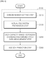
- FIG. 1 is a flowchart illustrating a procedure of the present invention for solving the above-described problems.
- the present invention does not obtain a single charging/discharging cycle by charging or discharging the entire capacity of the ESS at a time, and divides the total capacity of the measurement target ESS virtually to obtain the charging/discharging cycle data for each divided capacity range thereby predicting the SOH of the whole ESS.
- the capacity virtual division step of the present invention is a step of virtually dividing the entire capacity of the measurement target ESS into two or more virtual capacities and may include a division number setting step of setting how many ranges the total capacity of the measurement target ESS is divided into.
- the division number setting step is a step of setting how many ranges the entire measurement target ESS capacity should be virtually divided into.
- each range may have a capacity range of 20.
- the charging/discharging cycle data measured in the actual ESS may be capacity data of the actual ESS after charging/discharging is performed within the divided capacity range every time.
- a capacity retention rate indicating a ratio of how much the initial capacity is retained is calculated, and the SOH of the battery may be predicted from the capacity retention rate. For example, when the reference capacity retention rate determined as an aging or replacement state of the ESS is 10%, after 4,000 charging/discharging cycles, when the calculated capacity retention rate falls below the reference capacity retention rate, the SOH of the ESS may be estimated to be 4,000 charging/discharging.
- the initial state capacity of each actual ESS is the initial state capacity of the division range divided by each capacity range.
- the SOH of the ESS is predicted, and this may be reflected in the operation of the ESS.
- the SOH of the ESS when the SOH of the ESS is reduced to have only about 70% of the initial capacity, it may replace the ESS with a new ESS, or reduce the number of electronic connections powered by the ESS.
- the actual ESS for each capacity range may be set so that the capacity range of the actual ESS matches the divided capacity range based on the output voltage of the actual ESS.
- FIG. 2 is a flowchart illustrating a method of performing charging/discharging of an actual ESS within a range of 61 to 80 when an ESS having a total capacity range of 1 to 100 is divided into 5.
- an actual ESS that obtains charging/discharging cycle data in the range of 61 to 80 may be set to perform charging/discharging only between the first reference output voltage corresponding to the 80 capacity of the actual ESS and the second reference output voltage corresponding to the 61 capacity of the actual system.
- discharging as comparing the output voltage of the actual ESS with the second reference voltage, when the output voltage of the actual ESS is equal to or higher than the second reference voltage, discharging is subsequently performed, and when the output voltage of the actual ESS is less than the second reference output voltage, discharging is stopped and charging is performed.
- charging as comparing the output voltage of the actual ESS with the first reference voltage, when the output voltage of the actual ESS is less than the first reference voltage, charging is subsequently performed, and when the output voltage of the actual ESS exceeds the first reference output voltage, charging is stopped and discharging is performed.
- the actual ESS may perform charging/discharging only within the range of 61 to 80.
- Each range-dependent charging/discharging cycle data measurement step of the present invention obtains charging/discharging cycle data while charging/discharging an actual ESS set for each of the capacity ranges.
- the first actual ESS is set to perform charging/discharging only within a capacity range of 81 to 100 of the measurement target ESS and measures a capacity in each charging/discharging cycle for a capacity range of 81 to 100 while charging/discharging the first actual ESS.
- the second actual ESS is set to perform charging/discharging only within a capacity range of 61 to 80 of the measurement target ESS and measures a capacity in each charging/discharging cycle for a capacity range of 61 to 80 while charging/discharging the second actual ESS.
- the third actual ESS is set to perform charging/discharging only within a capacity range of 41 to 60 of the measurement target ESS and measures a capacity in each charging/discharging cycle for a capacity range of 41 to 60 while charging/discharging the third actual ESS.
- the fourth actual ESS is set to perform charging/discharging only within a capacity range of 21 to 40 of the measurement target ESS and measures the capacity in each charging/discharging cycle for a capacity range of 21 to 40 while charging/discharging the fourth actual ESS.
- the fifth actual ESS is set to perform charging/discharging only within a range of 1 to 20 of the measurement target ESS and measures the capacity in each charging/discharging cycle for the 1 to 20 capacity range while charging/discharging the fifth actual ESS.
- the second actual ESS sets a first reference voltage matching the upper limit capacitance 80 of the second actual ESS and a second reference voltage matching the lower limit capacitance 61 of the second actual ESS.
- the first reference output voltage is compared with the output voltage of the second actual ESS (S240).
- the output voltage of the second actual ESS is equal to or less than the first reference voltage
- charging is performed continuously (S230).
- the output voltage of the second actual ESS exceeds the first reference output voltage, charging is stopped and discharging is performed.
- the second reference output voltage is compared with the output voltage of the second actual ESS (S220), when the output voltage of the second actual ESS is equal to or greater than the second reference output voltage, subsequently, discharging is performed (S210) and when the output voltage of the second actual ESS is less than the second reference output voltage, the discharging of the second actual ESS is stopped and charging is performed. Therefore, the second actual ESS may repeat the charging/discharging only within the range of 61 to 80 of the measurement target ESS to measure the capacity in each charging/discharging cycle of the second actual ESS.
- the ranges for virtually dividing the measurement target ESS are not overlapped.
- the ranges for virtually dividing the measurement target ESS may be implemented to be partially overlapped.
- the first actual ESS may be set to have a capacity range of 76 to 100
- the second actual ESS may be set to have a capacity range of 56 to 80
- the third actual ESS may be set to have a dosage range of 36 to 60
- the fourth actual ESS may be set to have a capacity range of 16 to 40
- the fifth actual ESS may be set to have a capacity range of 1 to 25.
- a capacity measurement method in a capacity range of the first to fifth actual ESSs and each charging/discharging cycle may be performed in the same manner as the method of setting the capacity range of the first to fifth actual ESSs when the range for virtually dividing the measurement target ESS is not overlapped and the capacity measurement method in each charging/discharging cycle.
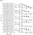
- FIG. 3 is a result of measuring charging/discharging cycle data of each of the first to fifth actual ESSs corresponding to the divided capacity ranges according to the embodiment of the present invention.
- the graph on the left is a graph showing that the first to fifth actual ESSs are charged/discharged by dividing the measurement target ESS by each range
- the five graphs shown on the right are graphs showing the capacity retention rates measured in the first to fifth actual ESSs.
- the capacity ranges of the first to fifth actual ESSs are set to include the capacity of the measurement target ESS, thereby measuring the capacity in the charging/discharging cycle throughout the capacity range of the measurement target ESS.
- the total SOH of the battery may be predicted.
- the ESS SOH prediction step of the present invention predicts the SOH of the measurement target ESS based on the charging/discharging cycle data measured in each of the plurality of actual ESSs set for each divided capacity range.
- the measurement target ESS SOH is predicted through three methods based on the charging/discharging cycle data measured in the actual ESS set for each divided capacity range.
- the charging/discharging cycle data measured in each of the plurality of actual ESSs set in the respective capacity ranges may be simply summed to predict the SOH of the measurement target of the ESS.
- the combination sum of the charging/discharging cycle data measured in each of the plurality of actual ESSs set in the respective capacity ranges may be calculated to predict the SOH of the measurement target ESS.
- the SOH of the measurement target ESS may be predicted.
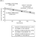
- FIG. 4 is a graph in which the charging/discharging range of a plurality of actual ESSs (first to fifth ESSs) is set to correspond to each divided capacity range according to the procedure of the embodiment of the present invention and the result of the prediction of the SOH of the measurement target ESS through the above three methods based on actual ESS charging/discharging data corresponding to each capacity range is compared with the SOH (prior art) of the measurement target ESS that is predicted while charging/discharging the measurement target ESS at a time.
- SOH prior art
- the time taken to obtain the charging/discharging cycle data for the total capacity of the measurement target ESS is further reduced as the division number of dividing the total capacity of the ESS increases.
- the SOH of the entire ESS may be measured quickly while satisfying the reliability.
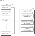
- FIG. 5 is a view illustrating an ESS SOH prediction device 1 according to a first embodiment of the present invention.
- the ESS SOH prediction device 1 may be configured including a plurality of actual Energy Storage Systems (ESSs) 10, and an analysis unit 100 for analyzing charging/discharging cycle data measured from each of the plurality of actual ESSs 10.
- ESSs actual Energy Storage Systems
- the number of the actual ESSs 10 is equal to or greater than the number of capacity ranges divided by the virtual capacity division unit 120 described later.
- the number of actual ESSs performing charging/discharging may be determined depending on the number of capacity ranges in the virtual capacity division unit.
- the analysis unit 100 may be configured including a virtual capacity division unit 110 for virtually dividing the capacity of the ESS to be measured into two or more capacity ranges, a reference voltage setting unit 120 for setting a first reference voltage and a second reference voltage matched to the divided capacitance range, and an ESS SOH prediction unit 130 for predicting the SOH of the ESS from the input charging/discharging cycle data.
- a virtual capacity division unit 110 for virtually dividing the capacity of the ESS to be measured into two or more capacity ranges
- a reference voltage setting unit 120 for setting a first reference voltage and a second reference voltage matched to the divided capacitance range
- an ESS SOH prediction unit 130 for predicting the SOH of the ESS from the input charging/discharging cycle data.
- the analysis unit 100 may repeat a charging or discharging process of each actual ESS 10 to measure charging/discharging cycle data for each divided capacity range after a first reference voltage and a second reference voltage matched to the divided capacitance range are transmitted to each of the plurality of actual ESSs.
- the virtual capacity division unit 110 may set virtually divided capacity ranges to overlap with each other by a predetermined range.
- the first reference voltage is a value corresponding to an upper limit capacity of each divided capacity range
- the second reference voltage is a value corresponding to a lower limit capacity of each divided capacity range.
- the first reference voltage is greater than the second reference voltage.
- Each of the plurality of actual ESSs 10 may be configured to include a BSC 11 for controlling charging/discharging of the actual ESS 10.
- the BSC stops charging and performs discharging, and when the initial output voltage of the actual ESS is greater than or equal to the second reference voltage, after discharging is performed until the output voltage of the actual ESS becomes the second reference voltage, when the output voltage of the actual ESS becomes less than the second reference voltage, the BSC may control the actual ESS 10 to stop discharging and perform charging.
- the plurality of actual ESSs 10 are discharged until a second reference voltage is obtained, and then charged until a first reference voltage is obtained. Thereafter, the plurality of actual ESSs 10 may measure the charging/discharging cycle data by continuously repeating the discharging process until reaching the second reference voltage.
- the BSC 11 may charge each actual ESS to a charge upper limit capacity within a capacity range allocated to each actual ESS, and may control the actual ESS to repeat the process of discharging to the charge lower limit capacity.
- the BSC 11 may transmit charging/discharging cycle data to the ESS SOH prediction unit.
- the ESS SOH prediction unit 130 may predict the SOH of the ESS through at least one of a first method for estimating the SOH of the ESS by simply summing the charging/discharging cycle data for each capacity range measured in each of the plurality of actual ESSs, a second method for predicting ESS SOH by summing up charging/discharging cycle data for each capacity range measured in each of the plurality of actual ESSs, and a third method for estimating ESS SOH using a multiplicative probability of charging/discharging cycle data for each capacity range measured in each of the plurality of actual ESSs.
- the ESS SOH prediction device 2 may be configured including a plurality of actual Energy Storage Systems (ESSs) 10, and an analysis unit 100 for analyzing charging/discharging cycle data measured from each of the plurality of actual ESSs 10.
- ESSs actual Energy Storage Systems
- the analysis unit 100 may be configured including a virtual capacity division unit 110 for virtually dividing the capacity of the ESS to be measured into two or more capacity ranges, a reference voltage setting unit 120 for setting a first reference voltage and a second reference voltage matched to the divided capacitance range, and an ESS SOH prediction unit 130 for predicting the SOH of the ESS from the input charging/discharging cycle data.
- a virtual capacity division unit 110 for virtually dividing the capacity of the ESS to be measured into two or more capacity ranges
- a reference voltage setting unit 120 for setting a first reference voltage and a second reference voltage matched to the divided capacitance range
- an ESS SOH prediction unit 130 for predicting the SOH of the ESS from the input charging/discharging cycle data.
- the analysis unit 100 may repeat a charging or discharging process of each actual ESS 10 to measure charging/discharging cycle data for each divided capacity range after a first reference voltage and a second reference voltage matched to the divided capacitance range are transmitted to each of the plurality of actual ESSs.
- the number of capacity ranges divided by the virtual capacity division unit 110 is equal to or less than the number of actual ESSs.
- the number of actual ESSs since the number of actual ESSs is limited, in order to actually charge/discharge the actual ESS by allocating each capacity range to actual ESS, the number of divided capacity ranges may not exceed the number of actual ESSs.
- the capacity range divided by the virtual capacity division unit 110 and allocated to each actual ESS is the same as the number of the actual ESSs.
- the virtual capacity division unit 110 may set virtually divided capacity ranges to overlap with each other by a predetermined range.
- the first reference voltage is a value corresponding to an upper limit capacity of each divided capacity range
- the second reference voltage is a value corresponding to a lower limit capacity of each divided capacity range.
- the first reference voltage is greater than the second reference voltage.
- each of the plurality of actual ESSs 10 may be configured to include a BSC 11 for controlling charging/discharging of the actual ESS 10.
- the BSC stops charging and performs discharging, and when the initial output voltage of the actual ESS is greater than or equal to the second reference voltage, after discharging is performed until the output voltage of the actual ESS becomes the second reference voltage, when the output voltage of the actual ESS becomes less than the second reference voltage, the BSC may control the actual ESS 10 to stop discharging and perform charging.
- the plurality of actual ESSs 10 are discharged until a second reference voltage is obtained, and then charged until a first reference voltage is obtained. Thereafter, the plurality of actual ESSs 10 may measure the charging/discharging cycle data by continuously repeating the discharging process until reaching the second reference voltage.
- the BSC 11 may charge each actual ESS to a charge upper limit capacity within a capacity range allocated to each actual ESS, and may control the actual ESS to repeat the process of discharging to the charge lower limit capacity.
- the BSC 11 may transmit charging/discharging cycle data to the ESS SOH prediction unit.
- the ESS SOH prediction unit 130 may predict the SOH of the ESS through at least one of a first method for estimating the SOH of the ESS by simply summing the charging/discharging cycle data for each capacity range measured in each of the plurality of actual ESSs, a second method for predicting ESS SOH by summing up charging/discharging cycle data for each capacity range measured in each of the plurality of actual ESSs, and a third method for estimating ESS SOH using a multiplicative probability of charging/discharging cycle data for each capacity range measured in each of the plurality of actual ESSs.
Landscapes
- Physics & Mathematics (AREA)
- General Physics & Mathematics (AREA)
- Charge And Discharge Circuits For Batteries Or The Like (AREA)
- Secondary Cells (AREA)
- Tests Of Electric Status Of Batteries (AREA)
Abstract
Description
- The present invention relates to a device and a method for rapidly predicting the SOH of a battery.
- More particularly, the present invention relates to a device and method for rapidly predicting the SOH of a battery by predicting the SOH of the battery by dividing it by sections.
- As the use of portable electrical appliances such as notebooks, video cameras is activated, the importance of the secondary battery, which is mainly used as a driving power source, is increasing.
- In addition, there is a growing need for an ESS for supplying a large capacity of power by connecting secondary batteries in series and in parallel.
- On the other hand, the importance of the technology related to the management system for more efficiently using and managing the ESS is increasing. Especially, in order to properly adjust the charging or discharging output and the State of Charge (SOC) usage strategy of the ESS, the management system must be able to accurately predict the State of Health (SOH) of the ESS.
- Generally, in order to predict the SOH in the ESS, ESS charging/discharging experiment data of about 4000 cycles or more were required. Conventionally, SOH experiments were performed while charging/discharging the entire battery capacity under actual use conditions. In this experiment, since only data of an average of 4 to 5 cycles are obtained per day, approximately 900 days were required to obtain about 4000 charging/discharging test data.
- Since the above-described conventional method obtains experimental data for predicting the SOH of the ESS over 30 months, it takes a long time to develop ESS, so that it was difficult to produce desired ESS in the market.
- To solve this problem, there was a method of predicting the SOH using extrapolation, but there is a problem that the reliability is worse due to a large error as compared with the actual SOH of the ESS.
- Therefore, the present invention proposes a device and method for maintaining the reliability of SOH prediction while reducing the time required to predict the SOH of the ESS.
- (Prior art document) Korean Patent Application Publication No.
10-2013-0089360 - The present invention attempts to solve the problem that it takes a long time to obtain data for predicting the SOH of the ESS of the prior art, and the SOH prediction of the ESS takes a long time.
- More specifically, the present invention provides a device and method for predicting the SOH of an ESS by dividing the capacity of the ESS into a plurality of capacity ranges to obtain charging/discharging cycle data of the ESS.
- According to an embodiment of the present invention, an ESS SOH prediction method includes: a capacity virtual division step of virtually dividing a capacity of a measurement target ESS that is to predict an SOH into two or more; each capacity range-dependent charging/discharging cycle data measurement step of measuring charging/discharging cycle data of each capacity range divided in the capacity virtual division step; and a measurement target ESS SOH prediction step of predicting an SOH of a measurement target ESS based on charging/discharging cycle data of each actual ESS measured in the each capacity range-dependent charging/discharging cycle data measurement step.
- The capacity virtual division step may include: a division range number setting step of setting how many ranges a total capacity of the measurement target ESS is divided; and an actual ESS preparation step of preparing an actual ESS as many as the number of division ranges of the measurement target ESS, wherein a range of an actual ESS may be set based on an output voltage to match the divided range, wherein the divided range of the actual ESS may be overlapped with ranges adjacent to each other by a predetermined range.
- The each capacity range-dependent charging/discharging cycle data measurement step may repeat the charging/discharging of the actual ESS corresponding to each capacity range divided in the capacity virtual division step to measure charging/discharging cycle data of the actual ESS corresponding to the each capacity range.
- The method of the repeating charging/discharging of the actual ESS may include: a first reference voltage setting step of setting a first reference voltage matching an upper limit capacity in each capacity range corresponding to the actual ESS; a second reference voltage setting step of setting a second reference voltage matching a lower limit capacity in each capacity range corresponding to the actual ESS; an output voltage measurement step of measuring an output voltage of the actual ESS; a comparison step of comparing the measured output voltage of the actual ESS with the first and second reference voltages; and a charging/discharging determination step of determining charging or discharging of the actual ESS according to a comparison result of the comparison step.
- The charging/discharging determination step may perform charging when the output voltage of the actual ESS is less than or equal to the first reference voltage according to the comparison result of the comparison step and stop charging and perform discharging when the output voltage of the actual ESS exceeds the first reference voltage.
- The charging/discharging determination step may perform discharging when the output voltage of the actual ESS is great than or equal to the second reference voltage according to the comparison result of the comparison step and stop discharging and perform charging when the output voltage of the actual ESS is less than the second reference voltage.
- The ESS SOH prediction step may predict an SOH of an ESS through at least one of: a first method for predicting the SOH of the ESS by simply summing each capacity range-dependent charging/discharging cycle data measured in the each capacity range-dependent charging/discharging cycle data measurement step; a second method for predicting the ESS SOH by a combination sum of each capacity range-dependent charging/discharging cycle data measured in the each capacity range-dependent charging/discharging cycle data measurement step; and a third method for predicting the ESS SOH using a multiplicative probability of each capacity range-dependent charging/discharging cycle data measured in the each capacity range-dependent charging/discharging cycle data measurement step.
- According to a first embodiment of the present invention, an ESS SOH prediction device includes: a plurality of actual Energy Storage Systems (ESSs); and an analysis unit for measuring and analyzing charging/discharging cycle data from each of the plurality of actual ESSs, wherein the analysis unit includes: a virtual capacity division unit for virtually dividing the capacity of the ESS to be measured into two or more capacity ranges; a reference voltage setting unit for setting a first reference voltage and a second reference voltage matching the divided capacitance range; and an ESS SOH prediction unit for predicting the SOH of the ESS from the inputted charging / discharging cycle data, wherein the number of actual ESSs is equal to or greater than the number of capacity ranges divided by the virtual capacity division unit, wherein the analysis unit transmits a first reference voltage and a second reference voltage matching the divided capacity range to the plurality of actual ESSs and repeats the charging or discharging process of each actual ESS to measure divided capacity range-dependent charging/discharging cycle data.
- The virtual capacity division unit may set the virtually divided capacity range to overlap ranges adjacent to each other by a predetermined range, wherein the first reference voltage is a value corresponding to an upper limit capacity of each divided capacity range, wherein the second reference voltage may be a value corresponding to a lower limit capacity of each divided capacity range, wherein the first reference voltage may be higher than the second reference voltage.
- Each of the plurality of actual ESSs may include a BSC for controlling charging/discharging of an actual ESS, wherein when the initial output voltage of the actual ESS is less than or equal to the first reference voltage, after charging is performed until the output voltage of the actual ESS becomes the first reference voltage, when the output voltage of the actual ESS exceeds the first reference voltage, the BSC may stop charging and perform discharging, wherein when the initial output voltage of the actual ESS is greater than or equal to the second reference voltage, after discharging is performed until the output voltage of the actual ESS becomes the second reference voltage, when the output voltage of the actual ESS becomes less than the second reference voltage, the BSC may stop discharging and perform charging.
- The ESS SOH prediction unit may predict an SOH of an ESS through at least one of: a first method for predicting the SOH of the ESS by simply summing each capacity range-dependent charging/discharging cycle data measured in each of the plurality of actual ESSs; a second method for predicting the ESS SOH by a combination sum of each capacity range-dependent charging/discharging cycle data measured in each of the plurality of actual ESSs; and a third method for predicting the ESS SOH using a multiplicative probability of each capacity range-dependent charging/discharging cycle data measured in each of the plurality of actual ESSs.
- According to a second embodiment of the present invention, an ESS SOH prediction device includes: a plurality of actual Energy Storage Systems (ESSs); and an analysis unit for measuring and analyzing charging/discharging cycle data from each of the plurality of actual ESSs, wherein the analysis unit includes: a virtual capacity division unit for virtually dividing the capacity of the ESS to be measured into two or more capacity ranges; a reference voltage setting unit for setting a first reference voltage and a second reference voltage matching the divided capacitance range; and an ESS SOH prediction unit for predicting the SOH of the ESS from the inputted charging / discharging cycle data, wherein the number of the two or more capacity ranges divided by the virtual capacity division unit is equal to or less than the actual ESS number, wherein the analysis unit transmits a first reference voltage and a second reference voltage matching the divided capacity range to the plurality of actual ESSs and repeats the charging or discharging process of each actual ESS to measure divided capacity range-dependent charging/discharging cycle data.
- The virtual capacity division unit may set the virtually divided capacity range to overlap ranges adjacent to each other by a predetermined range, wherein the first reference voltage may be a value corresponding to an upper limit capacity of each divided capacity range, wherein the second reference voltage may be a value corresponding to a lower limit capacity of each divided capacity range, wherein the first reference voltage may be higher than the second reference voltage.
- Each of the plurality of actual ESSs may include a BSC for controlling charging/discharging of an actual ESS, wherein when the initial output voltage of the actual ESS is less than or equal to the first reference voltage, after charging is performed until the output voltage of the actual ESS becomes the first reference voltage, when the output voltage of the actual ESS exceeds the first reference voltage, the BSC may stop charging and perform discharging, wherein when the initial output voltage of the actual ESS is greater than or equal to the second reference voltage, after discharging is performed until the output voltage of the actual ESS becomes the second reference voltage, when the output voltage of the actual ESS becomes less than the second reference voltage, the BSC may stop discharging and perform charging.
- The ESS SOH prediction unit may predict an SOH of an ESS through at least one of: a first method for predicting the SOH of the ESS by simply summing each capacity range-dependent charging/discharging cycle data measured in each of the plurality of actual ESSs; a second method for predicting the ESS SOH by a combination sum of each capacity range-dependent charging/discharging cycle data measured in each of the plurality of actual ESSs; and a third method for predicting the ESS SOH using a multiplicative probability of each capacity range-dependent charging/discharging cycle data measured in each of the plurality of actual ESSs.
- The present invention may divide the capacity range of the ESS into several capacity ranges and rapidly collect charging/discharging cycle data of the ESSs for each capacity range.
- In addition, by rapidly collecting the charging/discharging cycle data of the ESS for each capacity range, the SOH of the whole ESS may be predicted quickly.
-
-
FIG. 1 is a flowchart according to an embodiment. -
FIG. 2 is a flowchart illustrating a procedure for charging/discharging an ESS according to an embodiment of the present invention only within a set capacity range. -
FIG. 3 shows the result of measuring each charging/discharging cycle by dividing each of the first to fifth actual ESSs according to the embodiment of the present invention into five ranges. -
FIG. 4 is a graph comparing the result of predicting the SOH of the measurement target ESS according to the procedure of the embodiment of the present invention and the result of predicting the SOH of the measurement target ESS according to the prior art. -
FIG. 5 is a diagram illustrating an ESS SOH prediction device according to an embodiment of the present invention. - Hereinafter, embodiments of the present invention will be described in detail with reference to the accompanying drawings so that those skilled in the art may easily carry out the present invention. The present invention may, however, be embodied in different forms and should not be constructed as limited to the embodiments set forth herein. Parts not relating to description are omitted in the drawings in order to clearly describe the present invention and like reference numerals refer to like elements throughout.
- Although the terms "initial," "second," etc., may be used herein to describe various elements, these elements should not be limited by these terms. The above terms are used only to distinguish one component from another. For example, an initial component may be referred to as a second component and vice versa without departing from the scope of the present invention. Terms used in this specification are used to describe specific embodiments, and are not intended to limit the scope of the present invention. The singular expressions include plural expressions unless the context clearly dictates otherwise.
- Throughout the specification, when a portion is referred to as being "connected" to another portion, it includes not only "directly connected" but also "electrically connected" with another element therebetween. Furthermore, when it is described that one comprises (or includes or has) some elements, it should be understood that it may comprise (or include or has) only those elements, or it may comprise (or include or have) other elements as well as those elements when there is no specific limitation. The term "∼ing operation" or "operation of ∼ing" used throughout the specification does not mean "operation for ∼ing".
- Terms used in this specification may be currently widely used general terms in consideration of functions in the present invention but may vary according to the intents of those skilled in the art, precedents, or the advent of new technology. Additionally, in certain cases, there may be terms the applicant selects arbitrarily and in this case, their meanings are described in a corresponding description part of the present invention. Accordingly, terms used in the present invention should be defined based on the meaning of the term and the entire contents of the present invention instead of the simple term name.
- In the conventional method of predicting the SOH of the ESS, the entire ESS capacity is charged or discharged at a time to obtain charging/discharging cycle data. When the charging/discharging cycle data for the whole is obtained by charging or discharging the total ESS capacity at once, since it takes a long time to charge or discharge the entire ESS, it is possible to obtain only four to five charging/discharging cycle data per day, so that It took a long time to obtain sufficient charging/discharging cycle data (more than 4000 times) and to predict the SOH of the ESS based on this data.
-
FIG. 1 is a flowchart illustrating a procedure of the present invention for solving the above-described problems. - Hereinafter, a method of rapidly predicting SOH of the ESS of the present invention will be described with reference to
FIG. 1 . - The present invention does not obtain a single charging/discharging cycle by charging or discharging the entire capacity of the ESS at a time, and divides the total capacity of the measurement target ESS virtually to obtain the charging/discharging cycle data for each divided capacity range thereby predicting the SOH of the whole ESS.
- The capacity virtual division step of the present invention is a step of virtually dividing the entire capacity of the measurement target ESS into two or more virtual capacities and may include a division number setting step of setting how many ranges the total capacity of the measurement target ESS is divided into.
- The division number setting step is a step of setting how many ranges the entire measurement target ESS capacity should be virtually divided into.
- For example, when the ESS total capacity is between 1 and 100, and when the ESS total capacity is divided into five ranges, each range may have a capacity range of 20.
- When the capacity of the measurement target ESS is divided into five ranges as described above, since charging/discharging cycle data must be collected while charging/discharging for each range, five actual ESSs (first to fifth actual ESSs) having the same specifications as the measurement target ESS are required.
- In other words, in order to obtain charging/discharging cycle data of total capacity while charging/discharging each divided capacity range, an actual ESS corresponding to each of the capacity ranges divided in the division number setting step is required.
- Meanwhile, the charging/discharging cycle data measured in the actual ESS may be capacity data of the actual ESS after charging/discharging is performed within the divided capacity range every time.
- After charging/discharging is performed for each capacity divided from the capacity data measurement every time, a capacity retention rate indicating a ratio of how much the initial capacity is retained is calculated, and the SOH of the battery may be predicted from the capacity retention rate. For example, when the reference capacity retention rate determined as an aging or replacement state of the ESS is 10%, after 4,000 charging/discharging cycles, when the calculated capacity retention rate falls below the reference capacity retention rate, the SOH of the ESS may be estimated to be 4,000 charging/discharging. Here, the initial state capacity of each actual ESS is the initial state capacity of the division range divided by each capacity range.
- In relation to the ESS, when charging/discharging is repeatedly performed, because of the characteristics of the battery constituting the ESS, the capacity of the ESS is slightly reduced. As the capacity of the ESS is gradually reduced in such a manner, there is a problem that other devices powered by the ESS may not be operated normally.
- Therefore, based on the charging/discharging cycle data including the capacity retention rate, which is the result of comparing the capacity of the current ESS with the capacity in the initial state of the ESS, the SOH of the ESS is predicted, and this may be reflected in the operation of the ESS.
- For example, when the SOH of the ESS is reduced to have only about 70% of the initial capacity, it may replace the ESS with a new ESS, or reduce the number of electronic connections powered by the ESS.
- On the other hand, the actual ESS for each capacity range may be set so that the capacity range of the actual ESS matches the divided capacity range based on the output voltage of the actual ESS.
-
FIG. 2 is a flowchart illustrating a method of performing charging/discharging of an actual ESS within a range of 61 to 80 when an ESS having a total capacity range of 1 to 100 is divided into 5. - When the ESS with a total capacity range of 1 to 100 is divided into 5, an actual ESS that obtains charging/discharging cycle data in the range of 61 to 80 may be set to perform charging/discharging only between the first reference output voltage corresponding to the 80 capacity of the actual ESS and the second reference output voltage corresponding to the 61 capacity of the actual system.
- More specifically, during discharging, as comparing the output voltage of the actual ESS with the second reference voltage, when the output voltage of the actual ESS is equal to or higher than the second reference voltage, discharging is subsequently performed, and when the output voltage of the actual ESS is less than the second reference output voltage, discharging is stopped and charging is performed. On the other hand, during charging, as comparing the output voltage of the actual ESS with the first reference voltage, when the output voltage of the actual ESS is less than the first reference voltage, charging is subsequently performed, and when the output voltage of the actual ESS exceeds the first reference output voltage, charging is stopped and discharging is performed.
- As the above-described procedure, the actual ESS may perform charging/discharging only within the range of 61 to 80.
- Each range-dependent charging/discharging cycle data measurement step of the present invention obtains charging/discharging cycle data while charging/discharging an actual ESS set for each of the capacity ranges.
- In other words, the first actual ESS is set to perform charging/discharging only within a capacity range of 81 to 100 of the measurement target ESS and measures a capacity in each charging/discharging cycle for a capacity range of 81 to 100 while charging/discharging the first actual ESS. The second actual ESS is set to perform charging/discharging only within a capacity range of 61 to 80 of the measurement target ESS and measures a capacity in each charging/discharging cycle for a capacity range of 61 to 80 while charging/discharging the second actual ESS. The third actual ESS is set to perform charging/discharging only within a capacity range of 41 to 60 of the measurement target ESS and measures a capacity in each charging/discharging cycle for a capacity range of 41 to 60 while charging/discharging the third actual ESS. The fourth actual ESS is set to perform charging/discharging only within a capacity range of 21 to 40 of the measurement target ESS and measures the capacity in each charging/discharging cycle for a capacity range of 21 to 40 while charging/discharging the fourth actual ESS. The fifth actual ESS is set to perform charging/discharging only within a range of 1 to 20 of the measurement target ESS and measures the capacity in each charging/discharging cycle for the 1 to 20 capacity range while charging/discharging the fifth actual ESS.
- For example, the second actual ESS sets a first reference voltage matching the
upper limit capacitance 80 of the second actual ESS and a second reference voltage matching the lower limit capacitance 61 of the second actual ESS. - In the method of measuring the capacitance in each charging/discharging cycle of the second actual ESS, in which the first and second reference voltages are set, the first reference output voltage is compared with the output voltage of the second actual ESS (S240). When the output voltage of the second actual ESS is equal to or less than the first reference voltage, charging is performed continuously (S230). When the output voltage of the second actual ESS exceeds the first reference output voltage, charging is stopped and discharging is performed. As the second reference output voltage is compared with the output voltage of the second actual ESS (S220), when the output voltage of the second actual ESS is equal to or greater than the second reference output voltage, subsequently, discharging is performed (S210) and when the output voltage of the second actual ESS is less than the second reference output voltage, the discharging of the second actual ESS is stopped and charging is performed. Therefore, the second actual ESS may repeat the charging/discharging only within the range of 61 to 80 of the measurement target ESS to measure the capacity in each charging/discharging cycle of the second actual ESS.
- Meanwhile, in the above example, it is described that the ranges for virtually dividing the measurement target ESS are not overlapped. However, the ranges for virtually dividing the measurement target ESS may be implemented to be partially overlapped.
- In other words, the first actual ESS may be set to have a capacity range of 76 to 100, the second actual ESS may be set to have a capacity range of 56 to 80, the third actual ESS may be set to have a dosage range of 36 to 60, the fourth actual ESS may be set to have a capacity range of 16 to 40, and the fifth actual ESS may be set to have a capacity range of 1 to 25. At this time, a capacity measurement method in a capacity range of the first to fifth actual ESSs and each charging/discharging cycle may be performed in the same manner as the method of setting the capacity range of the first to fifth actual ESSs when the range for virtually dividing the measurement target ESS is not overlapped and the capacity measurement method in each charging/discharging cycle.
- When the divided ranges are designed to partially overlap with each other, by covering the error caused by the reduction in the use area of the cathode in the degradation of a particular section (for example,
SOC 60 to 40 section) is greater than that of the other section in the section-dependent degradation of the ESS, it is possible to reduce occurring errors.FIG. 3 is a result of measuring charging/discharging cycle data of each of the first to fifth actual ESSs corresponding to the divided capacity ranges according to the embodiment of the present invention. - Referring to
FIG. 3 , the graph on the left is a graph showing that the first to fifth actual ESSs are charged/discharged by dividing the measurement target ESS by each range, and the five graphs shown on the right are graphs showing the capacity retention rates measured in the first to fifth actual ESSs. - Referring to the five graphs on the right side of
FIG. 3 , it may be seen that there is a difference in the capacity retention rate when charging/discharging is repeated in each range. As the capacity retention rate differs for each range in such a manner, the capacity in the charging/discharging cycle is measured only a part of the measurement target ESS capacity range, and based on this, when estimating the total SOH of the measurement target ESS, a large error occurs. - Accordingly, in the present invention, without measuring the capacity in a charging/discharging cycle for only a certain period, the capacity ranges of the first to fifth actual ESSs are set to include the capacity of the measurement target ESS, thereby measuring the capacity in the charging/discharging cycle throughout the capacity range of the measurement target ESS.
- Meanwhile, in the ESS SOH prediction step described later, based on the capacity in the charging/discharging cycle measured in the entire capacity range of the first through fifth actual ESSs set as described above, the total SOH of the battery may be predicted.
- The ESS SOH prediction step of the present invention predicts the SOH of the measurement target ESS based on the charging/discharging cycle data measured in each of the plurality of actual ESSs set for each divided capacity range.
- Meanwhile, in the present invention, the measurement target ESS SOH is predicted through three methods based on the charging/discharging cycle data measured in the actual ESS set for each divided capacity range.
- First, the charging/discharging cycle data measured in each of the plurality of actual ESSs set in the respective capacity ranges may be simply summed to predict the SOH of the measurement target of the ESS.
- Second, the combination sum of the charging/discharging cycle data measured in each of the plurality of actual ESSs set in the respective capacity ranges may be calculated to predict the SOH of the measurement target ESS.
- Lastly, with the multiplicative probability of the charging/discharging cycle data measured in each of the plurality of actual ESSs set in the respective capacity ranges, the SOH of the measurement target ESS may be predicted.
- Meanwhile,
FIG. 4 is a graph in which the charging/discharging range of a plurality of actual ESSs (first to fifth ESSs) is set to correspond to each divided capacity range according to the procedure of the embodiment of the present invention and the result of the prediction of the SOH of the measurement target ESS through the above three methods based on actual ESS charging/discharging data corresponding to each capacity range is compared with the SOH (prior art) of the measurement target ESS that is predicted while charging/discharging the measurement target ESS at a time. Referring toFIG. 4 , it may be seen that it is within the error range of the SOH (prior art) of the measurement target ESS predicted while charging/discharging the measurement target ESS at once and the result of prediction of the SOH of the measurement target ESS predicted according to the procedure of the present invention. - Meanwhile, when using the method of the present invention, the time taken to obtain the charging/discharging cycle data for the total capacity of the measurement target ESS is further reduced as the division number of dividing the total capacity of the ESS increases.
- Therefore, by using the above-described method of the present invention, the SOH of the entire ESS may be measured quickly while satisfying the reliability.
-
FIG. 5 is a view illustrating an ESSSOH prediction device 1 according to a first embodiment of the present invention. - The ESS
SOH prediction device 1 according to the first embodiment of the present invention may be configured including a plurality of actual Energy Storage Systems (ESSs) 10, and ananalysis unit 100 for analyzing charging/discharging cycle data measured from each of the plurality ofactual ESSs 10. - Meanwhile, it is preferable that the number of the
actual ESSs 10 is equal to or greater than the number of capacity ranges divided by the virtualcapacity division unit 120 described later. - In other words, in the ESS SOH prediction device according to the first embodiment of the present invention, depending on the number of capacity ranges in the virtual capacity division unit, the number of actual ESSs performing charging/discharging may be determined.
- Meanwhile, the
analysis unit 100 may be configured including a virtualcapacity division unit 110 for virtually dividing the capacity of the ESS to be measured into two or more capacity ranges, a referencevoltage setting unit 120 for setting a first reference voltage and a second reference voltage matched to the divided capacitance range, and an ESSSOH prediction unit 130 for predicting the SOH of the ESS from the input charging/discharging cycle data. - Then, the
analysis unit 100 may repeat a charging or discharging process of eachactual ESS 10 to measure charging/discharging cycle data for each divided capacity range after a first reference voltage and a second reference voltage matched to the divided capacitance range are transmitted to each of the plurality of actual ESSs. - Meanwhile, the virtual
capacity division unit 110 may set virtually divided capacity ranges to overlap with each other by a predetermined range. - The first reference voltage is a value corresponding to an upper limit capacity of each divided capacity range, and the second reference voltage is a value corresponding to a lower limit capacity of each divided capacity range. The first reference voltage is greater than the second reference voltage.
- Each of the plurality of
actual ESSs 10 may be configured to include aBSC 11 for controlling charging/discharging of theactual ESS 10. - Specifically, when the initial output voltage of the actual ESS is less than or equal to the first reference voltage, after the charging is performed until the output voltage of the actual ESS becomes the first reference voltage, when the output voltage of the actual ESS exceeds the first reference voltage, the BSC stops charging and performs discharging, and when the initial output voltage of the actual ESS is greater than or equal to the second reference voltage, after discharging is performed until the output voltage of the actual ESS becomes the second reference voltage, when the output voltage of the actual ESS becomes less than the second reference voltage, the BSC may control the
actual ESS 10 to stop discharging and perform charging. - For example, when the initial output voltage exceeds the first reference voltage, the plurality of
actual ESSs 10 are discharged until a second reference voltage is obtained, and then charged until a first reference voltage is obtained. Thereafter, the plurality ofactual ESSs 10 may measure the charging/discharging cycle data by continuously repeating the discharging process until reaching the second reference voltage. In other words, theBSC 11 may charge each actual ESS to a charge upper limit capacity within a capacity range allocated to each actual ESS, and may control the actual ESS to repeat the process of discharging to the charge lower limit capacity. - Meanwhile, the
BSC 11 may transmit charging/discharging cycle data to the ESS SOH prediction unit. - Meanwhile, the ESS
SOH prediction unit 130 may predict the SOH of the ESS through at least one of a first method for estimating the SOH of the ESS by simply summing the charging/discharging cycle data for each capacity range measured in each of the plurality of actual ESSs, a second method for predicting ESS SOH by summing up charging/discharging cycle data for each capacity range measured in each of the plurality of actual ESSs, and a third method for estimating ESS SOH using a multiplicative probability of charging/discharging cycle data for each capacity range measured in each of the plurality of actual ESSs. - The ESS SOH prediction device 2 according to the first embodiment of the present invention may be configured including a plurality of actual Energy Storage Systems (ESSs) 10, and an
analysis unit 100 for analyzing charging/discharging cycle data measured from each of the plurality ofactual ESSs 10. - Meanwhile, the
analysis unit 100 may be configured including a virtualcapacity division unit 110 for virtually dividing the capacity of the ESS to be measured into two or more capacity ranges, a referencevoltage setting unit 120 for setting a first reference voltage and a second reference voltage matched to the divided capacitance range, and an ESSSOH prediction unit 130 for predicting the SOH of the ESS from the input charging/discharging cycle data. - Then, the
analysis unit 100 may repeat a charging or discharging process of eachactual ESS 10 to measure charging/discharging cycle data for each divided capacity range after a first reference voltage and a second reference voltage matched to the divided capacitance range are transmitted to each of the plurality of actual ESSs. - Meanwhile, it is preferable that the number of capacity ranges divided by the virtual
capacity division unit 110 is equal to or less than the number of actual ESSs. - In other words, since the number of actual ESSs is limited, in order to actually charge/discharge the actual ESS by allocating each capacity range to actual ESS, the number of divided capacity ranges may not exceed the number of actual ESSs.
- Meanwhile, it is most preferable that the capacity range divided by the virtual
capacity division unit 110 and allocated to each actual ESS is the same as the number of the actual ESSs. - For example, when the capacity range divided by the virtual
capacity division unit 110 is equal to the actual ESS number, based onEquation 1 below, the capacity range of each actual ESS may be calculated.
(where k = 1, 2, ..., N; N is a divisor of 100 excluding 1 and 100) - Meanwhile, the virtual
capacity division unit 110 may set virtually divided capacity ranges to overlap with each other by a predetermined range. - The first reference voltage is a value corresponding to an upper limit capacity of each divided capacity range, and the second reference voltage is a value corresponding to a lower limit capacity of each divided capacity range. The first reference voltage is greater than the second reference voltage.
- On the other hand, each of the plurality of
actual ESSs 10 may be configured to include aBSC 11 for controlling charging/discharging of theactual ESS 10. - Specifically, when the initial output voltage of the actual ESS is less than or equal to the first reference voltage, after the charging is performed until the output voltage of the actual ESS becomes the first reference voltage, when the output voltage of the actual ESS exceeds the first reference voltage, the BSC stops charging and performs discharging, and when the initial output voltage of the actual ESS is greater than or equal to the second reference voltage, after discharging is performed until the output voltage of the actual ESS becomes the second reference voltage, when the output voltage of the actual ESS becomes less than the second reference voltage, the BSC may control the
actual ESS 10 to stop discharging and perform charging. - For example, when the initial output voltage exceeds the first reference voltage, the plurality of
actual ESSs 10 are discharged until a second reference voltage is obtained, and then charged until a first reference voltage is obtained. Thereafter, the plurality ofactual ESSs 10 may measure the charging/discharging cycle data by continuously repeating the discharging process until reaching the second reference voltage. In other words, theBSC 11 may charge each actual ESS to a charge upper limit capacity within a capacity range allocated to each actual ESS, and may control the actual ESS to repeat the process of discharging to the charge lower limit capacity. - Meanwhile, the
BSC 11 may transmit charging/discharging cycle data to the ESS SOH prediction unit. - Meanwhile, the ESS
SOH prediction unit 130 may predict the SOH of the ESS through at least one of a first method for estimating the SOH of the ESS by simply summing the charging/discharging cycle data for each capacity range measured in each of the plurality of actual ESSs, a second method for predicting ESS SOH by summing up charging/discharging cycle data for each capacity range measured in each of the plurality of actual ESSs, and a third method for estimating ESS SOH using a multiplicative probability of charging/discharging cycle data for each capacity range measured in each of the plurality of actual ESSs. - On the other hand, although the technical idea of the present invention is specifically described with reference to the above embodiments, it should be noted that the above embodiments are for the purpose of explanation and not for the purpose of limitation. It will be apparent to those skilled in the art that various modifications and variations may be made in the present invention without departing from the spirit and scope of the invention.
Claims (15)
- An ESS SOH prediction method comprising:a capacity virtual division step of virtually dividing a capacity of a measurement target ESS that is to predict an SOH into two or more;each capacity range-dependent charging/discharging cycle data measurement step of measuring charging/discharging cycle data of each capacity range divided in the capacity virtual division step; anda measurement target ESS SOH prediction step of predicting an SOH of a measurement target ESS based on charging/discharging cycle data of each actual ESS measured in the each capacity range-dependent charging/discharging cycle data measurement step.
- The method of claim 1, wherein the capacity virtual division step comprises:a division range number setting step of setting how many ranges a total capacity of the measurement target ESS is divided; andan actual ESS preparation step of preparing an actual ESS as many as the number of division ranges of the measurement target ESS,wherein a range of an actual ESS is set based on an output voltage to match the divided range,wherein the divided range of the actual ESS is overlapped with ranges adjacent to each other by a predetermined range.
- The method of claim 2, wherein the each capacity range-dependent charging/discharging cycle data measurement step repeats the charging/discharging of the actual ESS corresponding to each capacity range divided in the capacity virtual division step to measure charging/discharging cycle data of the actual ESS corresponding to the each capacity range.
- The method of claim 3, wherein the method of the repeating charging/discharging of the actual ESS comprises:a first reference voltage setting step of setting a first reference voltage matching an upper limit capacity in each capacity range corresponding to the actual ESS;a second reference voltage setting step of setting a second reference voltage matching a lower limit capacity in each capacity range corresponding to the actual ESS;an output voltage measurement step of measuring an output voltage of the actual ESS;a comparison step of comparing the measured output voltage of the actual ESS with the first and second reference voltages; anda charging/discharging determination step of determining charging or discharging of the actual ESS according to a comparison result of the comparison step.
- The method of claim 4, wherein the charging/discharging determination step performs charging when the output voltage of the actual ESS is less than or equal to the first reference voltage according to the comparison result of the comparison step and stops charging and performs discharging when the output voltage of the actual ESS exceeds the first reference voltage.
- The method of claim 4, wherein the charging/discharging determination step performs discharging when the output voltage of the actual ESS is great than or equal to the second reference voltage according to the comparison result of the comparison step and stops discharging and performs charging when the output voltage of the actual ESS is less than the second reference voltage.
- The method of claim 1, wherein the ESS SOH prediction step predicts an SOH of an ESS through at least one of:a first method for predicting the SOH of the ESS by simply summing each capacity range-dependent charging/discharging cycle data measured in the each capacity range-dependent charging/discharging cycle data measurement step;a second method for predicting the ESS SOH by a combination sum of each capacity range-dependent charging/discharging cycle data measured in the each capacity range-dependent charging/discharging cycle data measurement step; anda third method for predicting the ESS SOH using a multiplicative probability of each capacity range-dependent charging/discharging cycle data measured in the each capacity range-dependent charging/discharging cycle data measurement step.
- An ESS SOH prediction device comprising:a plurality of actual Energy Storage Systems (ESSs); andan analysis unit for measuring and analyzing charging/discharging cycle data from each of the plurality of actual ESSs,wherein the analysis unit comprises:a virtual capacity division unit for virtually dividing the capacity of the ESS to be measured into two or more capacity ranges;a reference voltage setting unit for setting a first reference voltage and a second reference voltage matching the divided capacitance range; andan ESS SOH prediction unit for predicting the SOH of the ESS from the inputted charging / discharging cycle data,wherein the number of actual ESSs is equal to or greater than the number of capacity ranges divided by the virtual capacity division unit,wherein the analysis unit transmits a first reference voltage and a second reference voltage matching the divided capacity range to the plurality of actual ESSs and repeats the charging or discharging process of each actual ESS to measure divided capacity range-dependent charging/discharging cycle data.
- The device of claim 8, wherein the virtual capacity division unit sets the virtually divided capacity range to overlap ranges adjacent to each other by a predetermined range,
wherein the first reference voltage is a value corresponding to an upper limit capacity of each divided capacity range,
wherein the second reference voltage is a value corresponding to a lower limit capacity of each divided capacity range,
wherein the first reference voltage is higher than the second reference voltage. - The device of claim 8, wherein each of the plurality of actual ESSs comprises a BSC for controlling charging/discharging of an actual ESS,
wherein when the initial output voltage of the actual ESS is less than or equal to the first reference voltage, after charging is performed until the output voltage of the actual ESS becomes the first reference voltage, when the output voltage of the actual ESS exceeds the first reference voltage, the BSC stops charging and performs discharging,
wherein when the initial output voltage of the actual ESS is greater than or equal to the second reference voltage, after discharging is performed until the output voltage of the actual ESS becomes the second reference voltage, when the output voltage of the actual ESS becomes less than the second reference voltage, the BSC stops discharging and performs charging. - The device of claim 3, wherein the ESS SOH prediction unit predicts an SOH of an ESS through at least one of:a first method for predicting the SOH of the ESS by simply summing each capacity range-dependent charging/discharging cycle data measured in each of the plurality of actual ESSs;a second method for predicting the ESS SOH by a combination sum of each capacity range-dependent charging/discharging cycle data measured in each of the plurality of actual ESSs; anda third method for predicting the ESS SOH using a multiplicative probability of each capacity range-dependent charging/discharging cycle data measured in each of the plurality of actual ESSs.
- An ESS SOH prediction device comprising:a plurality of actual Energy Storage Systems (ESSs); andan analysis unit for measuring and analyzing charging/discharging cycle data from each of the plurality of actual ESSs,wherein the analysis unit comprises:a virtual capacity division unit for virtually dividing the capacity of the ESS to be measured into two or more capacity ranges;a reference voltage setting unit for setting a first reference voltage and a second reference voltage matching the divided capacitance range; andan ESS SOH prediction unit for predicting the SOH of the ESS from the inputted charging / discharging cycle data,wherein the number of the two or more capacity ranges divided by the virtual capacity division unit is equal to or less than the actual ESS number,wherein the analysis unit transmits a first reference voltage and a second reference voltage matching the divided capacity range to the plurality of actual ESSs and repeats the charging or discharging process of each actual ESS to measure divided capacity range-dependent charging/discharging cycle data.
- The device of claim 12, wherein the virtual capacity division unit sets the virtually divided capacity range to overlap ranges adjacent to each other by a predetermined range,
wherein the first reference voltage is a value corresponding to an upper limit capacity of each divided capacity range,
wherein the second reference voltage is a value corresponding to a lower limit capacity of each divided capacity range,
wherein the first reference voltage is higher than the second reference voltage. - The device of claim 12, wherein each of the plurality of actual ESSs comprises a BSC for controlling charging/discharging of an actual ESS,
wherein when the initial output voltage of the actual ESS is less than or equal to the first reference voltage, after charging is performed until the output voltage of the actual ESS becomes the first reference voltage, when the output voltage of the actual ESS exceeds the first reference voltage, the BSC stops charging and performs discharging,
wherein when the initial output voltage of the actual ESS is greater than or equal to the second reference voltage, after discharging is performed until the output voltage of the actual ESS becomes the second reference voltage, when the output voltage of the actual ESS becomes less than the second reference voltage, the BSC stops discharging and performs charging. - The device of claim 12, wherein the ESS SOH prediction unit predicts an SOH of an ESS through at least one of:a first method for predicting the SOH of the ESS by simply summing each capacity range-dependent charging/discharging cycle data measured in each of the plurality of actual ESSs;a second method for predicting the ESS SOH by a combination sum of each capacity range-dependent charging/discharging cycle data measured in each of the plurality of actual ESSs; anda third method for predicting the ESS SOH using a multiplicative probability of each capacity range-dependent charging/discharging cycle data measured in each of the plurality of actual ESSs.
Applications Claiming Priority (3)
| Application Number | Priority Date | Filing Date | Title |
|---|---|---|---|
| KR20180027052 | 2018-03-07 | ||
| KR1020190025819A KR102291133B1 (en) | 2018-03-07 | 2019-03-06 | Apparatus and method for predict battery life |
| PCT/KR2019/002681 WO2019172692A1 (en) | 2018-03-07 | 2019-03-07 | Device and method for predicting state-of-health of battery |
Publications (3)
| Publication Number | Publication Date |
|---|---|
| EP3712629A1 true EP3712629A1 (en) | 2020-09-23 |
| EP3712629A4 EP3712629A4 (en) | 2020-12-23 |
| EP3712629B1 EP3712629B1 (en) | 2024-10-30 |
Family
ID=68071020
Family Applications (1)
| Application Number | Title | Priority Date | Filing Date |
|---|---|---|---|
| EP19763572.5A Active EP3712629B1 (en) | 2018-03-07 | 2019-03-07 | Device and method for predicting state-of-health of battery |
Country Status (8)
| Country | Link |
|---|---|
| US (1) | US11307263B2 (en) |
| EP (1) | EP3712629B1 (en) |
| JP (1) | JP7062198B2 (en) |
| KR (1) | KR102291133B1 (en) |
| CN (1) | CN111448469B (en) |
| ES (1) | ES2994685T3 (en) |
| HU (1) | HUE069107T2 (en) |
| PL (1) | PL3712629T3 (en) |
Families Citing this family (11)
| Publication number | Priority date | Publication date | Assignee | Title |
|---|---|---|---|---|
| CN101484382A (en) * | 2006-07-05 | 2009-07-15 | 伊藤勲 | Hydrogen generating method, hydrogen generating alloy and method for manufacturing hydrogen generating alloy |
| ES2991479T3 (en) * | 2019-08-23 | 2024-12-03 | Lg Energy Solution Ltd | Method for predicting the health status of a battery and battery group that employs it |
| CN111707954A (en) * | 2020-06-18 | 2020-09-25 | 中汽研汽车检验中心(天津)有限公司 | A kind of lithium iron phosphate power battery life prediction method |
| KR102848074B1 (en) | 2020-08-21 | 2025-08-19 | 주식회사 엘지에너지솔루션 | Method for predicting the life of a battery cell reflecting the storage characteristics of the positive electrode active material |
| WO2022075655A1 (en) | 2020-10-06 | 2022-04-14 | Samsung Electronics Co., Ltd. | Methods and systems for detecting faulty behavior in a battery |
| KR102872608B1 (en) * | 2020-11-09 | 2025-10-16 | 주식회사 엘지에너지솔루션 | Method and apparatus for predicting dischage time of battery |
| KR102911911B1 (en) * | 2021-04-29 | 2026-01-13 | 한국전기연구원 | Method for predicting available capacity of battery and apparatus thereof |
| CN113359051B (en) * | 2021-06-08 | 2024-08-20 | 北京车和家信息技术有限公司 | Method, device, equipment, medium and vehicle for evaluating health state of battery module |
| KR102618037B1 (en) | 2022-06-20 | 2023-12-27 | 주식회사 엘지에너지솔루션 | Battery diagnosis apparatus, battery diagnosis method, and battery diagnosis system |
| US12109909B2 (en) * | 2022-08-11 | 2024-10-08 | GM Global Technology Operations LLC | Goal-based electric vehicle charging |
| CN119046671B (en) * | 2024-10-31 | 2025-04-08 | 青岛科技大学 | Improved data segmentation lithium ion battery SOH estimation method based on transducer encoder |
Family Cites Families (33)
| Publication number | Priority date | Publication date | Assignee | Title |
|---|---|---|---|---|
| JP3618472B2 (en) | 1996-07-01 | 2005-02-09 | 富士通株式会社 | Battery unit and device using battery unit |
| JP3458785B2 (en) * | 1999-08-31 | 2003-10-20 | サンケン電気株式会社 | Battery life determination apparatus and method |
| JP3878397B2 (en) | 2000-07-19 | 2007-02-07 | 九州電力株式会社 | Secondary battery full charge, battery deterioration degree and dischargeable capacity determination method and apparatus |
| US7429849B2 (en) * | 2003-11-26 | 2008-09-30 | Toyo System Co., Ltd. | Method and apparatus for confirming the charge amount and degradation state of a battery, a storage medium, an information processing apparatus, and an electronic apparatus |
| US9366732B2 (en) | 2009-09-04 | 2016-06-14 | Board Of Regents, The University Of Texas System | Estimation of state-of-health in batteries |
| DE102010031337A1 (en) | 2010-07-14 | 2012-01-19 | Sb Limotive Company Ltd. | Method for determining the probable lifetime of at least one battery cell, battery having a plurality of battery cells and motor vehicle |
| CN102520367A (en) | 2011-12-26 | 2012-06-27 | 中国电子科技集团公司第十八研究所 | Method for evaluating life of space hydrogen-nickel storage batteries |
| KR101498761B1 (en) | 2012-02-02 | 2015-03-04 | 주식회사 엘지화학 | Apparatus and method of estimating state of health for battery, and battery management system using the same |
| KR101338348B1 (en) * | 2012-05-25 | 2013-12-06 | 주식회사 피엠그로우 | System and method for aging battery unit of battery pack |
| US9297861B2 (en) * | 2012-11-28 | 2016-03-29 | Changs Ascending Enterprise Co., Ltd. | State of health determination without unnoticed battery shut down |
| KR101865972B1 (en) | 2012-12-27 | 2018-06-08 | 현대자동차주식회사 | Method for checking deterioration of battery |
| CN103197257A (en) * | 2013-04-03 | 2013-07-10 | 华为技术有限公司 | Method and device for detecting state of health (SOH) of battery |
| CN103344917B (en) * | 2013-06-13 | 2015-08-12 | 北京交通大学 | A kind of lithium battery cycle life method for rapidly testing |
| US10073145B2 (en) * | 2013-07-04 | 2018-09-11 | Lg Chem, Ltd. | Method and system for estimating state of charge of battery |
| CN103389471B (en) * | 2013-07-25 | 2015-12-09 | 哈尔滨工业大学 | A kind of based on the cycle life of lithium ion battery indirect predictions method of GPR with indeterminacy section |
| JP2015099042A (en) | 2013-11-18 | 2015-05-28 | ローム株式会社 | Battery remaining amount estimation device, power supply system using the same, and electronic device |
| JP6224130B2 (en) | 2013-12-27 | 2017-11-01 | 三洋電機株式会社 | Control system, vehicle power supply |
| KR102225667B1 (en) * | 2014-07-02 | 2021-03-12 | 삼성전자주식회사 | Method and apparatus for estimating state of battery |
| KR102241683B1 (en) * | 2014-07-30 | 2021-04-19 | 삼성전자주식회사 | Method and apparatus for estimating state of battery |
| JP6238314B2 (en) | 2015-02-26 | 2017-11-29 | 学校法人立命館 | Storage battery deterioration diagnosis method and storage battery deterioration diagnosis apparatus |
| US10006967B2 (en) | 2015-10-16 | 2018-06-26 | Samsung Electronics Co., Ltd. | Battery management system for predicting life of a reconfigurable battery pack |
| JP6868976B2 (en) | 2015-12-17 | 2021-05-12 | ローム株式会社 | Deterioration estimation method for rechargeable batteries, deterioration estimation circuit, and electronic devices and automobiles using it |
| KR101772036B1 (en) * | 2015-12-30 | 2017-08-28 | 주식회사 효성 | Battery life estimation method and device of it |
| KR102117316B1 (en) | 2016-07-06 | 2020-06-01 | 주식회사 엘지화학 | Device for Estimating Usable Capacity of Secondary Battery by Using CC/CV Ratio |
| CN107045103B (en) | 2016-11-29 | 2020-02-04 | 北京长城华冠汽车科技股份有限公司 | Device and method for testing service life of power battery of electric automobile |
| CN110476072B (en) | 2017-03-29 | 2022-11-04 | 株式会社杰士汤浅国际 | Degradation estimating device, degradation estimating method, and recording medium |
| JP6428958B2 (en) | 2017-03-29 | 2018-11-28 | 株式会社Gsユアサ | Degradation estimation apparatus, degradation estimation method, and computer program |
| CN107024664B (en) * | 2017-04-01 | 2019-04-12 | 湖南银杏数据科技有限公司 | Lithium battery remaining life quick predict method based on constant-current charge segment |
| CN107015157B (en) * | 2017-04-01 | 2019-04-16 | 湖南银杏数据科技有限公司 | The lithium battery cycles left service life online fast test method of segment is risen based on constant current equipressure |
| CN107271913B (en) * | 2017-06-28 | 2019-03-22 | 北京工业大学 | A method applied to the prediction of the remaining capacity of the power battery |
| CN107768708A (en) | 2017-08-28 | 2018-03-06 | 天津力神电池股份有限公司 | The fast appraisement method of lithium battery graphite cathode material cycle performance |
| CN107728072A (en) | 2017-10-10 | 2018-02-23 | 合肥国轩高科动力能源有限公司 | A rapid prediction method for the cycle life of lithium-ion batteries |
| CN112834944B (en) * | 2020-12-30 | 2023-03-07 | 上海兰钧新能源科技有限公司 | Lithium battery accelerated cycle life testing method, device, medium and equipment |
-
2019
- 2019-03-06 KR KR1020190025819A patent/KR102291133B1/en active Active
- 2019-03-07 EP EP19763572.5A patent/EP3712629B1/en active Active
- 2019-03-07 US US16/956,832 patent/US11307263B2/en active Active
- 2019-03-07 PL PL19763572.5T patent/PL3712629T3/en unknown
- 2019-03-07 CN CN201980006323.2A patent/CN111448469B/en active Active
- 2019-03-07 ES ES19763572T patent/ES2994685T3/en active Active
- 2019-03-07 JP JP2020549541A patent/JP7062198B2/en active Active
- 2019-03-07 HU HUE19763572A patent/HUE069107T2/en unknown
Also Published As
| Publication number | Publication date |
|---|---|
| JP7062198B2 (en) | 2022-05-06 |
| EP3712629A4 (en) | 2020-12-23 |
| KR20190106763A (en) | 2019-09-18 |
| EP3712629B1 (en) | 2024-10-30 |
| HUE069107T2 (en) | 2025-02-28 |
| PL3712629T3 (en) | 2025-04-14 |
| US20200408848A1 (en) | 2020-12-31 |
| KR102291133B1 (en) | 2021-08-20 |
| JP2021505911A (en) | 2021-02-18 |
| CN111448469A (en) | 2020-07-24 |
| CN111448469B (en) | 2022-07-08 |
| US11307263B2 (en) | 2022-04-19 |
| ES2994685T3 (en) | 2025-01-29 |
Similar Documents
| Publication | Publication Date | Title |
|---|---|---|
| EP3712629B1 (en) | Device and method for predicting state-of-health of battery | |
| US10211487B2 (en) | Method for predicting battery health in consideration of temperature of battery management system | |
| EP3916411B1 (en) | Device and method for estimating state of battery | |
| US11029363B2 (en) | Method and device for predicting battery life | |
| EP3145021B1 (en) | Secondary-battery monitoring device and method for predicting capacity of secondary battery | |
| Micea et al. | Online state-of-health assessment for battery management systems | |
| KR102554505B1 (en) | Apparatus and method for diagnosing battery | |
| EP1688754B1 (en) | Battery management apparatus | |
| US7573237B2 (en) | System and method for monitoring battery state | |
| EP3106892B1 (en) | State estimation device and state estimation method | |
| EP2963433B1 (en) | Method and apparatus for estimating state of battery | |
| KR20210074003A (en) | Apparatus and method for diagnosing degeneracy of battery | |
| US20250147114A1 (en) | Apparatus and method for estimating battery state of health | |
| CN108387847B (en) | Charging and discharging test method for rechargeable battery, computer equipment and storage medium | |
| JP7845635B2 (en) | Battery management device and method | |
| CN115066622B (en) | Method for predicting service life of battery cell reflecting storage characteristic of positive electrode active material | |
| EP4109626B1 (en) | State-of-charge cutoff method and apparatus, and control system and storage medium | |
| CN115868063B (en) | Information processing method and charging control device | |
| KR20210115277A (en) | Battery management system and battery management method | |
| KR20240099042A (en) | Diagnosis apparatus, battery manufacturing system, battery pack, electric vehicle and diagnosis method | |
| US20250317000A1 (en) | Charge/discharge control device, charge/discharge control method, and program | |
| KR20250111280A (en) | Apparatus for managing battery data and operating method of the same | |
| WO2018029849A1 (en) | Estimation device, estimation program, and charging control device | |
| KR20240003510A (en) | Apparatus for battery management and method for caculating battery health | |
| EP4006564A1 (en) | Method for predicting soh of battery and battery pack employing same |
Legal Events
| Date | Code | Title | Description |
|---|---|---|---|
| STAA | Information on the status of an ep patent application or granted ep patent |
Free format text: STATUS: THE INTERNATIONAL PUBLICATION HAS BEEN MADE |
|
| PUAI | Public reference made under article 153(3) epc to a published international application that has entered the european phase |
Free format text: ORIGINAL CODE: 0009012 |
|
| STAA | Information on the status of an ep patent application or granted ep patent |
Free format text: STATUS: REQUEST FOR EXAMINATION WAS MADE |
|
| 17P | Request for examination filed |
Effective date: 20200616 |
|
| AK | Designated contracting states |
Kind code of ref document: A1 Designated state(s): AL AT BE BG CH CY CZ DE DK EE ES FI FR GB GR HR HU IE IS IT LI LT LU LV MC MK MT NL NO PL PT RO RS SE SI SK SM TR |
|
| AX | Request for extension of the european patent |
Extension state: BA ME |
|
| RIN1 | Information on inventor provided before grant (corrected) |
Inventor name: KIM, JEE HO Inventor name: CHUNG, DAE SIK |
|
| A4 | Supplementary search report drawn up and despatched |
Effective date: 20201120 |
|
| RIC1 | Information provided on ipc code assigned before grant |
Ipc: G01R 31/367 20190101ALI20201116BHEP Ipc: G01R 31/392 20190101AFI20201116BHEP Ipc: G01R 31/36 20200101ALI20201116BHEP |
|
| DAV | Request for validation of the european patent (deleted) | ||
| DAX | Request for extension of the european patent (deleted) | ||
| RAP1 | Party data changed (applicant data changed or rights of an application transferred) |
Owner name: LG ENERGY SOLUTION LTD. |
|
| RAP3 | Party data changed (applicant data changed or rights of an application transferred) |
Owner name: LG ENERGY SOLUTION, LTD. |
|
| STAA | Information on the status of an ep patent application or granted ep patent |
Free format text: STATUS: EXAMINATION IS IN PROGRESS |
|
| 17Q | First examination report despatched |
Effective date: 20221216 |
|
| GRAP | Despatch of communication of intention to grant a patent |
Free format text: ORIGINAL CODE: EPIDOSNIGR1 |
|
| STAA | Information on the status of an ep patent application or granted ep patent |
Free format text: STATUS: GRANT OF PATENT IS INTENDED |
|
| INTG | Intention to grant announced |
Effective date: 20240716 |
|
| P01 | Opt-out of the competence of the unified patent court (upc) registered |
Free format text: CASE NUMBER: APP_44501/2024 Effective date: 20240731 |
|
| GRAS | Grant fee paid |
Free format text: ORIGINAL CODE: EPIDOSNIGR3 |
|
| GRAA | (expected) grant |
Free format text: ORIGINAL CODE: 0009210 |
|
| STAA | Information on the status of an ep patent application or granted ep patent |
Free format text: STATUS: THE PATENT HAS BEEN GRANTED |
|
| AK | Designated contracting states |
Kind code of ref document: B1 Designated state(s): AL AT BE BG CH CY CZ DE DK EE ES FI FR GB GR HR HU IE IS IT LI LT LU LV MC MK MT NL NO PL PT RO RS SE SI SK SM TR |
|
| REG | Reference to a national code |
Ref country code: GB Ref legal event code: FG4D |
|
| REG | Reference to a national code |
Ref country code: CH Ref legal event code: EP |
|
| REG | Reference to a national code |
Ref country code: DE Ref legal event code: R096 Ref document number: 602019061155 Country of ref document: DE |
|
| REG | Reference to a national code |
Ref country code: NL Ref legal event code: FP Ref country code: IE Ref legal event code: FG4D |
|
| REG | Reference to a national code |
Ref country code: SE Ref legal event code: TRGR |
|
| REG | Reference to a national code |
Ref country code: ES Ref legal event code: FG2A Ref document number: 2994685 Country of ref document: ES Kind code of ref document: T3 Effective date: 20250129 |
|
| REG | Reference to a national code |
Ref country code: LT Ref legal event code: MG9D |
|
| REG | Reference to a national code |
Ref country code: HU Ref legal event code: AG4A Ref document number: E069107 Country of ref document: HU |
|
| PG25 | Lapsed in a contracting state [announced via postgrant information from national office to epo] |
Ref country code: IS Free format text: LAPSE BECAUSE OF FAILURE TO SUBMIT A TRANSLATION OF THE DESCRIPTION OR TO PAY THE FEE WITHIN THE PRESCRIBED TIME-LIMIT Effective date: 20250228 Ref country code: HR Free format text: LAPSE BECAUSE OF FAILURE TO SUBMIT A TRANSLATION OF THE DESCRIPTION OR TO PAY THE FEE WITHIN THE PRESCRIBED TIME-LIMIT Effective date: 20241030 Ref country code: PT Free format text: LAPSE BECAUSE OF FAILURE TO SUBMIT A TRANSLATION OF THE DESCRIPTION OR TO PAY THE FEE WITHIN THE PRESCRIBED TIME-LIMIT Effective date: 20250228 |
|
| PG25 | Lapsed in a contracting state [announced via postgrant information from national office to epo] |
Ref country code: FI Free format text: LAPSE BECAUSE OF FAILURE TO SUBMIT A TRANSLATION OF THE DESCRIPTION OR TO PAY THE FEE WITHIN THE PRESCRIBED TIME-LIMIT Effective date: 20241030 |
|
| REG | Reference to a national code |
Ref country code: AT Ref legal event code: MK05 Ref document number: 1737380 Country of ref document: AT Kind code of ref document: T Effective date: 20241030 |
|
| PG25 | Lapsed in a contracting state [announced via postgrant information from national office to epo] |
Ref country code: BG Free format text: LAPSE BECAUSE OF FAILURE TO SUBMIT A TRANSLATION OF THE DESCRIPTION OR TO PAY THE FEE WITHIN THE PRESCRIBED TIME-LIMIT Effective date: 20241030 |
|
| PG25 | Lapsed in a contracting state [announced via postgrant information from national office to epo] |
Ref country code: NO Free format text: LAPSE BECAUSE OF FAILURE TO SUBMIT A TRANSLATION OF THE DESCRIPTION OR TO PAY THE FEE WITHIN THE PRESCRIBED TIME-LIMIT Effective date: 20250130 |
|
| PG25 | Lapsed in a contracting state [announced via postgrant information from national office to epo] |
Ref country code: LV Free format text: LAPSE BECAUSE OF FAILURE TO SUBMIT A TRANSLATION OF THE DESCRIPTION OR TO PAY THE FEE WITHIN THE PRESCRIBED TIME-LIMIT Effective date: 20241030 Ref country code: GR Free format text: LAPSE BECAUSE OF FAILURE TO SUBMIT A TRANSLATION OF THE DESCRIPTION OR TO PAY THE FEE WITHIN THE PRESCRIBED TIME-LIMIT Effective date: 20250131 Ref country code: AT Free format text: LAPSE BECAUSE OF FAILURE TO SUBMIT A TRANSLATION OF THE DESCRIPTION OR TO PAY THE FEE WITHIN THE PRESCRIBED TIME-LIMIT Effective date: 20241030 |
|
| PG25 | Lapsed in a contracting state [announced via postgrant information from national office to epo] |
Ref country code: RS Free format text: LAPSE BECAUSE OF FAILURE TO SUBMIT A TRANSLATION OF THE DESCRIPTION OR TO PAY THE FEE WITHIN THE PRESCRIBED TIME-LIMIT Effective date: 20250130 |
|
| PG25 | Lapsed in a contracting state [announced via postgrant information from national office to epo] |
Ref country code: SM Free format text: LAPSE BECAUSE OF FAILURE TO SUBMIT A TRANSLATION OF THE DESCRIPTION OR TO PAY THE FEE WITHIN THE PRESCRIBED TIME-LIMIT Effective date: 20241030 |
|
| PG25 | Lapsed in a contracting state [announced via postgrant information from national office to epo] |
Ref country code: DK Free format text: LAPSE BECAUSE OF FAILURE TO SUBMIT A TRANSLATION OF THE DESCRIPTION OR TO PAY THE FEE WITHIN THE PRESCRIBED TIME-LIMIT Effective date: 20241030 |
|
| PGFP | Annual fee paid to national office [announced via postgrant information from national office to epo] |
Ref country code: ES Payment date: 20250408 Year of fee payment: 7 |
|
| PG25 | Lapsed in a contracting state [announced via postgrant information from national office to epo] |
Ref country code: EE Free format text: LAPSE BECAUSE OF FAILURE TO SUBMIT A TRANSLATION OF THE DESCRIPTION OR TO PAY THE FEE WITHIN THE PRESCRIBED TIME-LIMIT Effective date: 20241030 |
|
| PG25 | Lapsed in a contracting state [announced via postgrant information from national office to epo] |
Ref country code: RO Free format text: LAPSE BECAUSE OF FAILURE TO SUBMIT A TRANSLATION OF THE DESCRIPTION OR TO PAY THE FEE WITHIN THE PRESCRIBED TIME-LIMIT Effective date: 20241030 |
|
| PG25 | Lapsed in a contracting state [announced via postgrant information from national office to epo] |
Ref country code: SK Free format text: LAPSE BECAUSE OF FAILURE TO SUBMIT A TRANSLATION OF THE DESCRIPTION OR TO PAY THE FEE WITHIN THE PRESCRIBED TIME-LIMIT Effective date: 20241030 |
|
| PG25 | Lapsed in a contracting state [announced via postgrant information from national office to epo] |
Ref country code: CZ Free format text: LAPSE BECAUSE OF FAILURE TO SUBMIT A TRANSLATION OF THE DESCRIPTION OR TO PAY THE FEE WITHIN THE PRESCRIBED TIME-LIMIT Effective date: 20241030 |
|
| REG | Reference to a national code |
Ref country code: DE Ref legal event code: R097 Ref document number: 602019061155 Country of ref document: DE |
|
| PLBE | No opposition filed within time limit |
Free format text: ORIGINAL CODE: 0009261 |
|
| STAA | Information on the status of an ep patent application or granted ep patent |
Free format text: STATUS: NO OPPOSITION FILED WITHIN TIME LIMIT |
|
| 26N | No opposition filed |
Effective date: 20250731 |
|
| PG25 | Lapsed in a contracting state [announced via postgrant information from national office to epo] |
Ref country code: MC Free format text: LAPSE BECAUSE OF FAILURE TO SUBMIT A TRANSLATION OF THE DESCRIPTION OR TO PAY THE FEE WITHIN THE PRESCRIBED TIME-LIMIT Effective date: 20241030 |
|
| REG | Reference to a national code |
Ref country code: CH Ref legal event code: H13 Free format text: ST27 STATUS EVENT CODE: U-0-0-H10-H13 (AS PROVIDED BY THE NATIONAL OFFICE) Effective date: 20251023 |
|
| PG25 | Lapsed in a contracting state [announced via postgrant information from national office to epo] |
Ref country code: LU Free format text: LAPSE BECAUSE OF NON-PAYMENT OF DUE FEES Effective date: 20250307 |
|
| PG25 | Lapsed in a contracting state [announced via postgrant information from national office to epo] |
Ref country code: CH Free format text: LAPSE BECAUSE OF NON-PAYMENT OF DUE FEES Effective date: 20250331 |
|
| PG25 | Lapsed in a contracting state [announced via postgrant information from national office to epo] |
Ref country code: IE Free format text: LAPSE BECAUSE OF NON-PAYMENT OF DUE FEES Effective date: 20250307 |
|
| PGFP | Annual fee paid to national office [announced via postgrant information from national office to epo] |
Ref country code: NL Payment date: 20260220 Year of fee payment: 8 |
|
| PGFP | Annual fee paid to national office [announced via postgrant information from national office to epo] |
Ref country code: SE Payment date: 20260223 Year of fee payment: 8 |
|
| PGFP | Annual fee paid to national office [announced via postgrant information from national office to epo] |
Ref country code: GB Payment date: 20260224 Year of fee payment: 8 |
|
| PGFP | Annual fee paid to national office [announced via postgrant information from national office to epo] |
Ref country code: DE Payment date: 20260220 Year of fee payment: 8 |
|
| PGFP | Annual fee paid to national office [announced via postgrant information from national office to epo] |
Ref country code: BE Payment date: 20260220 Year of fee payment: 8 Ref country code: IT Payment date: 20260223 Year of fee payment: 8 |
|
| PGFP | Annual fee paid to national office [announced via postgrant information from national office to epo] |
Ref country code: HU Payment date: 20260310 Year of fee payment: 8 |
|
| PGFP | Annual fee paid to national office [announced via postgrant information from national office to epo] |
Ref country code: FR Payment date: 20260224 Year of fee payment: 8 |
|
| PGFP | Annual fee paid to national office [announced via postgrant information from national office to epo] |
Ref country code: TR Payment date: 20260226 Year of fee payment: 8 |
|
| PGFP | Annual fee paid to national office [announced via postgrant information from national office to epo] |
Ref country code: PL Payment date: 20260223 Year of fee payment: 8 |