EP3712605A1 - Multi-zone automatic magnetoscop inspection system - Google Patents
Multi-zone automatic magnetoscop inspection system Download PDFInfo
- Publication number
- EP3712605A1 EP3712605A1 EP20161665.3A EP20161665A EP3712605A1 EP 3712605 A1 EP3712605 A1 EP 3712605A1 EP 20161665 A EP20161665 A EP 20161665A EP 3712605 A1 EP3712605 A1 EP 3712605A1
- Authority
- EP
- European Patent Office
- Prior art keywords
- magnetoscop
- profile
- turbine
- turbine component
- inspection system
- Prior art date
- Legal status (The legal status is an assumption and is not a legal conclusion. Google has not performed a legal analysis and makes no representation as to the accuracy of the status listed.)
- Granted
Links
Images



Classifications
-
- G—PHYSICS
- G01—MEASURING; TESTING
- G01N—INVESTIGATING OR ANALYSING MATERIALS BY DETERMINING THEIR CHEMICAL OR PHYSICAL PROPERTIES
- G01N27/00—Investigating or analysing materials by the use of electric, electrochemical, or magnetic means
- G01N27/72—Investigating or analysing materials by the use of electric, electrochemical, or magnetic means by investigating magnetic variables
- G01N27/82—Investigating or analysing materials by the use of electric, electrochemical, or magnetic means by investigating magnetic variables for investigating the presence of flaws
- G01N27/83—Investigating or analysing materials by the use of electric, electrochemical, or magnetic means by investigating magnetic variables for investigating the presence of flaws by investigating stray magnetic fields
-
- G—PHYSICS
- G01—MEASURING; TESTING
- G01M—TESTING STATIC OR DYNAMIC BALANCE OF MACHINES OR STRUCTURES; TESTING OF STRUCTURES OR APPARATUS, NOT OTHERWISE PROVIDED FOR
- G01M15/00—Testing of engines
- G01M15/14—Testing gas-turbine engines or jet-propulsion engines
-
- G—PHYSICS
- G01—MEASURING; TESTING
- G01N—INVESTIGATING OR ANALYSING MATERIALS BY DETERMINING THEIR CHEMICAL OR PHYSICAL PROPERTIES
- G01N23/00—Investigating or analysing materials by the use of wave or particle radiation, e.g. X-rays or neutrons, not covered by groups G01N3/00 – G01N17/00, G01N21/00 or G01N22/00
- G01N23/02—Investigating or analysing materials by the use of wave or particle radiation, e.g. X-rays or neutrons, not covered by groups G01N3/00 – G01N17/00, G01N21/00 or G01N22/00 by transmitting the radiation through the material
- G01N23/04—Investigating or analysing materials by the use of wave or particle radiation, e.g. X-rays or neutrons, not covered by groups G01N3/00 – G01N17/00, G01N21/00 or G01N22/00 by transmitting the radiation through the material and forming images of the material
- G01N23/046—Investigating or analysing materials by the use of wave or particle radiation, e.g. X-rays or neutrons, not covered by groups G01N3/00 – G01N17/00, G01N21/00 or G01N22/00 by transmitting the radiation through the material and forming images of the material using tomography, e.g. computed tomography [CT]
-
- G—PHYSICS
- G01—MEASURING; TESTING
- G01N—INVESTIGATING OR ANALYSING MATERIALS BY DETERMINING THEIR CHEMICAL OR PHYSICAL PROPERTIES
- G01N27/00—Investigating or analysing materials by the use of electric, electrochemical, or magnetic means
- G01N27/72—Investigating or analysing materials by the use of electric, electrochemical, or magnetic means by investigating magnetic variables
- G01N27/82—Investigating or analysing materials by the use of electric, electrochemical, or magnetic means by investigating magnetic variables for investigating the presence of flaws
-
- G—PHYSICS
- G01—MEASURING; TESTING
- G01N—INVESTIGATING OR ANALYSING MATERIALS BY DETERMINING THEIR CHEMICAL OR PHYSICAL PROPERTIES
- G01N2223/00—Investigating materials by wave or particle radiation
- G01N2223/30—Accessories, mechanical or electrical features
- G01N2223/304—Accessories, mechanical or electrical features electric circuits, signal processing
-
- G—PHYSICS
- G01—MEASURING; TESTING
- G01N—INVESTIGATING OR ANALYSING MATERIALS BY DETERMINING THEIR CHEMICAL OR PHYSICAL PROPERTIES
- G01N2223/00—Investigating materials by wave or particle radiation
- G01N2223/30—Accessories, mechanical or electrical features
- G01N2223/305—Accessories, mechanical or electrical features computer simulations
Definitions
- Embodiments of the present disclosure are related generally to an apparatus and method for inspecting a component of a gas turbine engine, and more specifically, to techniques for inspecting turbine airfoils included in a gas turbine engine.
- Gas turbine engines employed on an aircraft vehicle include a variety of internal components or airfoil components such as, for example, turbine blades and turbine vanes.
- the turbine blades and vanes can include internal cooling passages, which are frequently exposed to hot temperature environments that can contain rich oxygen levels and moisture. Continuous exposure to these environmental conditions can lead to corrosion of the internal walls of the cooling passages. This internal passage corrosion decreases the thickness of non-corroded wall portions and reduces the overall integrity of blades and/or vanes.
- a magnetoscop inspection system comprises a magnetoscop, a computed tomography (CT) unit, and a corrosion model unit.
- the magnetoscop is configured to measure a permeability at a plurality of inspection points of a turbine component.
- the CT unit is configured to generate a measured profile of a hollowed portion of the turbine component based at least in part on the permeability at the measured inspection points.
- the corrosion model unit is configured to store in memory at least one reference CT profile corresponding to a given known turbine component.
- the magnetoscop inspection system determines a structural integrity of the turbine component based on a comparison between the measured profile and a reference CT profile corresponding to the turbine component.
- a method to inspect a turbine blade included in a gas turbine engine.
- the method comprises storing, via a corrosion model unit, at least one reference CT profile corresponding to a given known turbine component, and measuring, via a magnetoscop, a permeability at a plurality of inspection points of the turbine component.
- the method further comprises generating, via a computed tomography (CT) unit, a measured profile of a hollowed portion of the turbine component based at least in part on the permeability at the measured inspection points.
- CT computed tomography
- the method further comprises determining a structural integrity of the turbine component based on a comparison between the measured profile and a reference CT profile corresponding to the turbine component.
- Turbine blades and/or vanes employed in gas turbine engines typically include various materials (e.g., nickel) susceptible to corrosion.
- the internal corrosion of turbine blades and/or vanes can cause depletion of pure nickel (Ni) from a base metal alloy, and in turn can causes the deposition of corrosion byproducts such nickel oxide (NiO), cobalt oxide (CoO), etc., on the internal wall(s) of the corroding component.
- Corrosion byproducts typically have ferromagnetic properties, which can be sensed by magnetoscop devices. Therefore, a computer generated image of the component's internal profile can be produced using various computed tomography (CT) techniques.
- CT computed tomography
- magnetoscops are capable of measuring the magnetic flux density and relative permeability within the scope of the quality control of stainless steel and low-permeable (non-magnetic) alloys as well as the localization of ferrite enclosures. Magnetoscops can also detect changes in material (sulfidation, degradation of lamination, structural changes) based on permeability comparative measurements.
- Turbine blades have complex geometries and profiles.
- Turbine blades for example, have an airfoil profile that includes both convex portions and concave portions. Consequently, attempts to inspect the internal wall of a turbine blade using only a magnetoscop can result in inaccurate measurements due to separations or boundaries between the concave portions and convex portions.
- a magnetoscop inspection system that includes a robotically controlled magnetoscop and a profile boundary controller.
- the robotically controlled magnetoscop includes a probe capable of scanning a turbine component (e.g., turbine blade) to detect a plurality of inspection points that define the inner-wall profile.
- the profile boundary controller analyzes the inspection points in combination with a physics-based model to determine different inner-wall profiles (e.g., concave profiles versus convex profiles) of a turbine engine component (e.g., a turbine blade), along with detecting boundaries between the different inner-wall profiles.
- the profile boundary controller analyzes neighborhood inspection points corresponding to a corroded portion(s) of the inner-wall, along with the CT wall thickness reading to calculate not only the thickness of the corrosion layer but also thicknesses of remaining non-corroded portions of the inner-wall
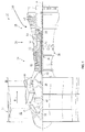
- a gas turbine engine 20 is schematically illustrated according to a non-limiting embodiment.
- the gas turbine engine 20 is disclosed herein as a two-spool turbofan that generally incorporates a fan section 22, a compressor section 24, a combustor section 26 and a turbine section 28.
- Alternative engines might include other systems or features.
- the fan section 22 drives air along a bypass flow path B in a bypass duct, while the compressor section 24 drives air along a core flow path C for compression and communication into the combustor section 26 then expansion through the turbine section 28.
- the exemplary engine 20 generally includes a low speed spool 30 and a high speed spool 32 mounted for rotation about an engine central longitudinal axis A relative to an engine static structure 36 via several bearing systems 38. It should be understood that various bearing systems 38 at various locations may alternatively or additionally be provided, and the location of bearing systems 38 may be varied as appropriate to the application.
- the low speed spool 30 generally includes an inner shaft 40 that interconnects a fan 42, a low pressure compressor 44 and a low pressure turbine 46.
- the inner shaft 40 is connected to the fan 42 through a speed change mechanism, which in exemplary gas turbine engine 20 is illustrated as a geared architecture 48 to drive the fan 42 at a lower speed than the low speed spool 30.
- the high speed spool 32 includes an outer shaft 50 that interconnects a high pressure compressor 52 and high pressure turbine 54.
- a combustor 56 is arranged in exemplary gas turbine 20 between the high pressure compressor 52 and the high pressure turbine 54.
- An engine static structure 36 is arranged generally between the high pressure turbine 54 and the low pressure turbine 46.
- the engine static structure 36 further supports bearing systems 38 in the turbine section 28.
- the inner shaft 40 and the outer shaft 50 are concentric and rotate via bearing systems 38 about the engine central longitudinal axis (A) which is collinear with their longitudinal axes.
- each of the positions of the fan section 22, compressor section 24, combustor section 26, turbine section 28, and fan drive gear system 48 may be varied.
- gear system 48 may be located aft of combustor section 26 or even aft of turbine section 28, and fan section 22 may be positioned forward or aft of the location of gear system 48.
- the engine 20 in one example is a high-bypass geared aircraft engine.
- the engine 20 bypass ratio is greater than about six (6), with an example embodiment being greater than about ten (10)
- the geared architecture 48 is an epicyclic gear train, such as a planetary gear system or other gear system, with a gear reduction ratio of greater than about 2.3 and the low pressure turbine 46 has a pressure ratio that is greater than about five.
- the engine 20 bypass ratio is greater than about ten (10:1)
- the fan diameter is significantly larger than that of the low pressure compressor 44
- the low pressure turbine 46 has a pressure ratio that is greater than about five (5:1).
- Low pressure turbine 46 pressure ratio is pressure measured prior to inlet of low pressure turbine 46 as related to the pressure at the outlet of the low pressure turbine 46 prior to an exhaust nozzle.
- the geared architecture 48 may be an epicycle gear train, such as a planetary gear system or other gear system, with a gear reduction ratio of greater than about 2.3:1. It should be understood, however, that the above parameters are only exemplary of one embodiment of a geared architecture engine and that the present disclosure is applicable to other gas turbine engines including direct drive turbofans.
- the fan section 22 of the engine 20 is designed for a particular flight condition--typically cruise at about 0.8 Mach and about 35,000 feet (10,668 meters).
- 'TSFC' Thrust Specific Fuel Consumption
- Low fan pressure ratio is the pressure ratio across the fan blade alone, without a Fan Exit Guide Vane (“FEGV”) system.
- the low fan pressure ratio as disclosed herein according to one non-limiting embodiment is less than about 1.45.
- Low corrected fan tip speed is the actual fan tip speed in ft/sec divided by an industry standard temperature correction of [(Tram °R)/(518.7 °R)]0.5.
- the "Low corrected fan tip speed” as disclosed herein according to one non-limiting embodiment is less than about 1150 ft/second (350.5 m/sec).
- a magnetoscop scanning inspection system 100 configured to inspect internal corrosion of a turbine blade 110 is illustrated according to a non-limiting embodiment.
- the turbine blade 110 includes a distal end 112, which is coupled to a rotor 114 of a turbine engine.
- a turbine blade 110 is illustrated as an example, the magnetoscop inspection system 100 is capable of scanning other turbine engine components or airfoil components such as, for example, a turbine vane.
- FIG. 4 A cross-section of the turbine blade 110 is illustrated in FIG. 4 .
- the turbine blade 110 includes hollow cooling passages 208 defined by a pressure-side wall 202 and a suction-side wall 204.
- the cooling passages 208 pass cool air therethrough as the pressure-side wall 202 and the suction-side wall 204 are exposed to heated core gas flow.
- a plurality of ribs 206 extend between the pressure-side wall 202 and the suction-side wall 204 to define each individual internal cooling passage 208.
- FIG. 5 is a close-up view of an internal section 250 of the turbine blade 110 including one of the cooling passages 208.
- the internal cooling passages 208 is bounded by an opposing pair of ribs 206, each which extends between the pressure-side wall 202 and the suction-side wall 204.
- the pressure-side wall 202 includes an outer pressure-side wall surface 210 and an inner pressure-side wall surface 212.
- the suction-side wall 204 includes an outer suction-side wall surface 214 and an inner suction-side wall surface 216.
- the pressure-side wall 202 has a first corroded element 218 formed thereon, while the suction-side wall 204 has a second corroded element 220 formed thereon. These corroded elements 218 and 220 have ferromagnetic properties, which can be detected and analyzed by the magnetoscop scanning inspection system 100.
- the magnetoscop scanning inspection system 100 includes a magnetoscop 102, a magnetoscop controller 104, and a graphic user interface (GUI) 106.
- the magnetoscop 102 is configured to scan a pressure-side surface 200a of the turbine blade 110 (see FIG. 2 ) and an opposing suction-side surface 200b of the turbine blade 110 (see FIG. 3 ).
- the magnetoscop 102 can be supported by a one or more robotically controlled mechanisms (not shown).
- the GUI 106 can display measurements, images, and/or analyzed results obtained from inspecting a turbine component.
- the GUI 106 can also receive various inputs, models, and/or commands for controlling the magnetoscop 102.
- the magnetoscop controller 104 can include a robotic control unit 108 that controls the operation of the robotic support mechanisms to facilitate autonomous scanning of the turbine blade 110.
- the robotic control unit 108 is also configured to actively adjust a position the magnetoscop 102 at a controlled orientation relative to the turbine blade 110 such that probe 103 is maintained at a set distance (D) away from the pressure-side surface 200a and the suction-side surface 200b. In this manner, the probe 103 can be prevented from scrapping directly against the surfaces 200a, 200b of the turbine blade 110, which in turn prevents damaging the probe 103 and scraping the turbine blade 110.
- the magnetoscop inspection system 100 can inspect and analyze the permeability from the perspective of the pressure-side surface 200a and the suction-side surface 200b of the turbine blade 110.
- the results e.g., detected magnetic flux permeability
- a threshold value to determine a structural integrity of the turbine blade 110. If the structural integrity of the turbine blade 110 is compromised then the turbine blade 110 may be overhauled or replaced. Accordingly, detecting permeability through the surfaces 200a, 200b can improve results of the inspection process.
- the magnetoscop controller 104 further includes a CT unit 116 and corrosion model unit 118.
- Any one of the robotic control unit 108, the CT unit 116, and the corrosion model unit 118 can be constructed as an electronic hardware controller that includes memory and a processor configured to execute algorithms and computer-readable program instructions stored in the memory.
- the robotic control unit 108, the CT unit 116, and the corrosion model unit 118 can all be embedded or integrated in a single sub-controller.
- the measured inspection points are fedback to the magnetoscop controller 104. Based at least in part on the permeability at the measured inspection points, the CT unit 116 generates a CT profile of the current state of the internal cooling passage 208.
- the current CT profile of the internal cooling passage 208 indicates the thicknesses of the pressure-side wall 202 and the suction-side wall 204 (see FIG. 5 ).
- the corrosion model unit 118 can store one or more available reference CT profiles corresponding to a given known turbine component (e.g., turbine blade, turbine vane, etc.).
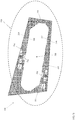
- FIG. 6 illustrates an example of a reference CT model 600 including an ideal cooling passage 602, which corresponds to the current measured CT profile 250 of the cooling passage 208 shown in the close-up section 250 illustrated in FIG. 5 .
- the magnetoscop inspection system 100 can utilize the current measured CT profile 250 of the cooling passage 208 along with the corresponding reference CT reference profile 600 including the ideal cooling passage 602 to calculate the thickness of the corrosion elements 218, 220, along with the thickness of remaining non-corrosion portions (D Y1 , D Y2 ) of the inner wall surfaces 212, 216 (see FIG. 5 ).
- a given turbine component, a particular instance (e.g., unique serial number) of the turbine component, or portion of the turbine component (e.g., an internal cooling passage of the turbine component) can be inspected prior to being made available for field operation, i.e., prior to being employed in a turbine engine for first time use.
- a reference CT profile 600 can be generated which indicates an expected or known profile of the internal cooling passage (i.e., an ideal cooling passage 602) of the given turbine component or the particular instance (e.g., unique serial number) of the turbine part, along with the expected or known thicknesses (D REF1 , D REF2 , D REFn ) of the pressure-side wall 202 and suction-side wall 204 prior to corrosion.
- the corrosion model unit 118 can utilize a stored reference CT profile (e.g., reference CT profile 600) corresponding to the component currently scanned to accurately inspect and analyze the current profile of scanned component.
- the corrosion model unit 118 can receive an input (e.g., component identification (ID)) via the GUI 106 indicating the type of turbine blade 110, particular instance (e.g., unique serial number) of the turbine component, etc., currently undergoing inspection. Based on the indicated turbine blade 110, the corrosion model unit 118 can obtain a corresponding reference CT profile from memory, and can compare the reference CT profile to the current measured CT profile generated from the measured inspection points that are fedback from the magnetoscop 102.
- ID component identification
- the corrosion model unit 118 can obtain the reference CT profile 600 (see FIG. 6 ) corresponding to the current measured CT profile of the internal section 250 of the turbine blade 110 (see FIG. 5 ). Accordingly, the corrosion model unit 118 can calculate thicknesses of the remaining non-corroded portions of the pressure-side wall 202 and the suction-side wall 204. In this example, the thickness of the remaining non-corroded portions of the pressure-side wall 202 can be determined as distance (D Y1 ) between the outer pressure-side wall surface 210 and the first corrosion element 218. Similarly the remaining non-corroded portions of the suction-side wall 204 can be determined as distance (D Y2 ) between the outer suction-side wall surface 214 and the second corrosion element 220. The corrosion model unit 118 can also calculate the thickness (D X1 , D X2 ) of the first and second corrosion elements 218 and 220, respectively.
- the magnetoscop scanning inspection system 100 can utilize the measured distances to determine the structural integrity of a turbine component, e.g., the turbine blade 110.
- the corrosion model unit 118 can compare the thickness of the remaining non-corroded portions (e.g., D Y1 , D Y2 , etc.) to a distance threshold and/or can compare the corrosion element thicknesses (D X1 , D X2 , etc.) to a thickness threshold.
- the corrosion model unit 118 can determine the component (e.g., turbine blade 110) is faulty, and generate an alert on the GUI 106. Accordingly, the component can be disposed of or destroyed to prevent it from being placed back into the field.
- the component e.g., turbine blade 110
Landscapes
- Chemical & Material Sciences (AREA)
- Health & Medical Sciences (AREA)
- General Physics & Mathematics (AREA)
- Physics & Mathematics (AREA)
- Immunology (AREA)
- Pathology (AREA)
- Analytical Chemistry (AREA)
- Biochemistry (AREA)
- General Health & Medical Sciences (AREA)
- Life Sciences & Earth Sciences (AREA)
- Engineering & Computer Science (AREA)
- Chemical Kinetics & Catalysis (AREA)
- Electrochemistry (AREA)
- Nuclear Medicine, Radiotherapy & Molecular Imaging (AREA)
- Pulmonology (AREA)
- Radiology & Medical Imaging (AREA)
- Theoretical Computer Science (AREA)
- Combustion & Propulsion (AREA)
- Testing Resistance To Weather, Investigating Materials By Mechanical Methods (AREA)
- Investigating Or Analyzing Materials By The Use Of Magnetic Means (AREA)
Abstract
Description
- Embodiments of the present disclosure are related generally to an apparatus and method for inspecting a component of a gas turbine engine, and more specifically, to techniques for inspecting turbine airfoils included in a gas turbine engine.
- Gas turbine engines employed on an aircraft vehicle include a variety of internal components or airfoil components such as, for example, turbine blades and turbine vanes. The turbine blades and vanes can include internal cooling passages, which are frequently exposed to hot temperature environments that can contain rich oxygen levels and moisture. Continuous exposure to these environmental conditions can lead to corrosion of the internal walls of the cooling passages. This internal passage corrosion decreases the thickness of non-corroded wall portions and reduces the overall integrity of blades and/or vanes.
- According to a non-limiting embodiment, a magnetoscop inspection system comprises a magnetoscop, a computed tomography (CT) unit, and a corrosion model unit. The magnetoscop is configured to measure a permeability at a plurality of inspection points of a turbine component. The CT unit is configured to generate a measured profile of a hollowed portion of the turbine component based at least in part on the permeability at the measured inspection points. The corrosion model unit is configured to store in memory at least one reference CT profile corresponding to a given known turbine component. The magnetoscop inspection system determines a structural integrity of the turbine component based on a comparison between the measured profile and a reference CT profile corresponding to the turbine component.
- According to another non-limiting embodiment, a method is provided to inspect a turbine blade included in a gas turbine engine. The method comprises storing, via a corrosion model unit, at least one reference CT profile corresponding to a given known turbine component, and measuring, via a magnetoscop, a permeability at a plurality of inspection points of the turbine component. The method further comprises generating, via a computed tomography (CT) unit, a measured profile of a hollowed portion of the turbine component based at least in part on the permeability at the measured inspection points. The method further comprises determining a structural integrity of the turbine component based on a comparison between the measured profile and a reference CT profile corresponding to the turbine component.
- The following descriptions are provided by way of example only and should not be considered limiting in any way. With reference to the accompanying drawings, like elements are numbered alike:
-
FIG. 1 is a partial cross-sectional view of a gas turbine engine; -
FIG. 2 illustrates a magnetoscop scanning a first surface of a turbine blade; -
FIG. 3 illustrates a magnetoscop scanning an opposing surface of the turbine blade illustrated inFIG. 2 ; -
FIG. 4 illustrates a cross-section of the turbine blade shown inFIG. 3 ; -
FIG. 5 is a close-up view of a measured profile of an internal section of the turbine blade including a cooling passage; and -
FIG. 6 illustrates a reference profile including an ideal cooling passage corresponding to the measured profile of the cooling passage shown inFIG. 5 . - A detailed description of one or more embodiments of the disclosed apparatus and method are presented herein by way of exemplification and not limitation with reference to the figures.
- Turbine blades and/or vanes employed in gas turbine engines typically include various materials (e.g., nickel) susceptible to corrosion. The internal corrosion of turbine blades and/or vanes, can cause depletion of pure nickel (Ni) from a base metal alloy, and in turn can causes the deposition of corrosion byproducts such nickel oxide (NiO), cobalt oxide (CoO), etc., on the internal wall(s) of the corroding component.
- Corrosion byproducts (e.g., NiO, CoO, etc.) typically have ferromagnetic properties, which can be sensed by magnetoscop devices. Therefore, a computer generated image of the component's internal profile can be produced using various computed tomography (CT) techniques. For example, magnetoscops are capable of measuring the magnetic flux density and relative permeability within the scope of the quality control of stainless steel and low-permeable (non-magnetic) alloys as well as the localization of ferrite enclosures. Magnetoscops can also detect changes in material (sulfidation, degradation of lamination, structural changes) based on permeability comparative measurements. However, the internal turbine internal components (e.g., blades and vanes) have complex geometries and profiles. Turbine blades, for example, have an airfoil profile that includes both convex portions and concave portions. Consequently, attempts to inspect the internal wall of a turbine blade using only a magnetoscop can result in inaccurate measurements due to separations or boundaries between the concave portions and convex portions.
- Various non-limiting embodiments described herein provide a magnetoscop inspection system that includes a robotically controlled magnetoscop and a profile boundary controller. The robotically controlled magnetoscop includes a probe capable of scanning a turbine component (e.g., turbine blade) to detect a plurality of inspection points that define the inner-wall profile. The profile boundary controller analyzes the inspection points in combination with a physics-based model to determine different inner-wall profiles (e.g., concave profiles versus convex profiles) of a turbine engine component (e.g., a turbine blade), along with detecting boundaries between the different inner-wall profiles. In at least one non-limiting embodiment, the profile boundary controller analyzes neighborhood inspection points corresponding to a corroded portion(s) of the inner-wall, along with the CT wall thickness reading to calculate not only the thickness of the corrosion layer but also thicknesses of remaining non-corroded portions of the inner-wall
- With reference now to
FIG. 1 , agas turbine engine 20 is schematically illustrated according to a non-limiting embodiment. Thegas turbine engine 20 is disclosed herein as a two-spool turbofan that generally incorporates afan section 22, acompressor section 24, acombustor section 26 and aturbine section 28. Alternative engines might include other systems or features. Thefan section 22 drives air along a bypass flow path B in a bypass duct, while thecompressor section 24 drives air along a core flow path C for compression and communication into thecombustor section 26 then expansion through theturbine section 28. Although depicted as a two-spool turbofan gas turbine engine in the disclosed non-limiting embodiment, it should be understood that the concepts described herein are not limited to use with two-spool turbofans as the teachings may be applied to other types of turbine engines including three-spool architectures. - The
exemplary engine 20 generally includes alow speed spool 30 and ahigh speed spool 32 mounted for rotation about an engine central longitudinal axis A relative to an engine static structure 36 viaseveral bearing systems 38. It should be understood thatvarious bearing systems 38 at various locations may alternatively or additionally be provided, and the location ofbearing systems 38 may be varied as appropriate to the application. - The
low speed spool 30 generally includes an inner shaft 40 that interconnects a fan 42, a low pressure compressor 44 and alow pressure turbine 46. The inner shaft 40 is connected to the fan 42 through a speed change mechanism, which in exemplarygas turbine engine 20 is illustrated as a geared architecture 48 to drive the fan 42 at a lower speed than thelow speed spool 30. Thehigh speed spool 32 includes anouter shaft 50 that interconnects ahigh pressure compressor 52 andhigh pressure turbine 54. Acombustor 56 is arranged inexemplary gas turbine 20 between thehigh pressure compressor 52 and thehigh pressure turbine 54. An engine static structure 36 is arranged generally between thehigh pressure turbine 54 and thelow pressure turbine 46. The engine static structure 36 further supports bearingsystems 38 in theturbine section 28. The inner shaft 40 and theouter shaft 50 are concentric and rotate viabearing systems 38 about the engine central longitudinal axis (A) which is collinear with their longitudinal axes. - The core airflow is compressed by the low pressure compressor 44 then the
high pressure compressor 52, mixed and burned with fuel in thecombustor 56, then expanded over thehigh pressure turbine 54 andlow pressure turbine 46. Theturbines low speed spool 30 andhigh speed spool 32 in response to the expansion. It will be appreciated that each of the positions of thefan section 22,compressor section 24,combustor section 26,turbine section 28, and fan drive gear system 48 may be varied. For example, gear system 48 may be located aft ofcombustor section 26 or even aft ofturbine section 28, andfan section 22 may be positioned forward or aft of the location of gear system 48. - The
engine 20 in one example is a high-bypass geared aircraft engine. In a further example, theengine 20 bypass ratio is greater than about six (6), with an example embodiment being greater than about ten (10), the geared architecture 48 is an epicyclic gear train, such as a planetary gear system or other gear system, with a gear reduction ratio of greater than about 2.3 and thelow pressure turbine 46 has a pressure ratio that is greater than about five. In one disclosed embodiment, theengine 20 bypass ratio is greater than about ten (10:1), the fan diameter is significantly larger than that of the low pressure compressor 44, and thelow pressure turbine 46 has a pressure ratio that is greater than about five (5:1).Low pressure turbine 46 pressure ratio is pressure measured prior to inlet oflow pressure turbine 46 as related to the pressure at the outlet of thelow pressure turbine 46 prior to an exhaust nozzle. The geared architecture 48 may be an epicycle gear train, such as a planetary gear system or other gear system, with a gear reduction ratio of greater than about 2.3:1. It should be understood, however, that the above parameters are only exemplary of one embodiment of a geared architecture engine and that the present disclosure is applicable to other gas turbine engines including direct drive turbofans. - A significant amount of thrust is provided by the bypass flow B due to the high bypass ratio. The
fan section 22 of theengine 20 is designed for a particular flight condition--typically cruise at about 0.8 Mach and about 35,000 feet (10,668 meters). The flight condition of 0.8 Mach and 35,000 ft (10,668 meters), with the engine at its best fuel consumption--also known as "bucket cruise Thrust Specific Fuel Consumption ('TSFC')"--is the industry standard parameter of Ibm of fuel being burned divided by lbf of thrust the engine produces at that minimum point. "Low fan pressure ratio" is the pressure ratio across the fan blade alone, without a Fan Exit Guide Vane ("FEGV") system. The low fan pressure ratio as disclosed herein according to one non-limiting embodiment is less than about 1.45. "Low corrected fan tip speed" is the actual fan tip speed in ft/sec divided by an industry standard temperature correction of [(Tram °R)/(518.7 °R)]0.5. The "Low corrected fan tip speed" as disclosed herein according to one non-limiting embodiment is less than about 1150 ft/second (350.5 m/sec). - Turning to
FIGS. 2 and 3 , a magnetoscopscanning inspection system 100 configured to inspect internal corrosion of aturbine blade 110 is illustrated according to a non-limiting embodiment. Theturbine blade 110 includes adistal end 112, which is coupled to arotor 114 of a turbine engine. Although aturbine blade 110 is illustrated as an example, themagnetoscop inspection system 100 is capable of scanning other turbine engine components or airfoil components such as, for example, a turbine vane. - A cross-section of the
turbine blade 110 is illustrated inFIG. 4 . Theturbine blade 110 includeshollow cooling passages 208 defined by a pressure-side wall 202 and a suction-side wall 204. Thecooling passages 208 pass cool air therethrough as the pressure-side wall 202 and the suction-side wall 204 are exposed to heated core gas flow. A plurality ofribs 206 extend between the pressure-side wall 202 and the suction-side wall 204 to define each individualinternal cooling passage 208. -
FIG. 5 is a close-up view of aninternal section 250 of theturbine blade 110 including one of thecooling passages 208. Theinternal cooling passages 208 is bounded by an opposing pair ofribs 206, each which extends between the pressure-side wall 202 and the suction-side wall 204. The pressure-side wall 202 includes an outer pressure-side wall surface 210 and an inner pressure-side wall surface 212. Similarly, the suction-side wall 204 includes an outer suction-side wall surface 214 and an inner suction-side wall surface 216. The pressure-side wall 202 has a firstcorroded element 218 formed thereon, while the suction-side wall 204 has a secondcorroded element 220 formed thereon. Thesecorroded elements scanning inspection system 100. - Referencing again
FIGS. 2 and 3 , the magnetoscopscanning inspection system 100 includes amagnetoscop 102, amagnetoscop controller 104, and a graphic user interface (GUI) 106. Themagnetoscop 102 is configured to scan a pressure-side surface 200a of the turbine blade 110 (seeFIG. 2 ) and an opposing suction-side surface 200b of the turbine blade 110 (seeFIG. 3 ). Themagnetoscop 102 can be supported by a one or more robotically controlled mechanisms (not shown). TheGUI 106 can display measurements, images, and/or analyzed results obtained from inspecting a turbine component. TheGUI 106 can also receive various inputs, models, and/or commands for controlling themagnetoscop 102. - The
magnetoscop controller 104 can include arobotic control unit 108 that controls the operation of the robotic support mechanisms to facilitate autonomous scanning of theturbine blade 110. Therobotic control unit 108 is also configured to actively adjust a position themagnetoscop 102 at a controlled orientation relative to theturbine blade 110 such thatprobe 103 is maintained at a set distance (D) away from the pressure-side surface 200a and the suction-side surface 200b. In this manner, theprobe 103 can be prevented from scrapping directly against thesurfaces turbine blade 110, which in turn prevents damaging theprobe 103 and scraping theturbine blade 110. - In at least one non-limiting embodiment, the
magnetoscop inspection system 100 can inspect and analyze the permeability from the perspective of the pressure-side surface 200a and the suction-side surface 200b of theturbine blade 110. The results (e.g., detected magnetic flux permeability) can be compared with a threshold value to determine a structural integrity of theturbine blade 110. If the structural integrity of theturbine blade 110 is compromised then theturbine blade 110 may be overhauled or replaced. Accordingly, detecting permeability through thesurfaces - The
magnetoscop controller 104 further includes aCT unit 116 andcorrosion model unit 118. Any one of therobotic control unit 108, theCT unit 116, and thecorrosion model unit 118 can be constructed as an electronic hardware controller that includes memory and a processor configured to execute algorithms and computer-readable program instructions stored in the memory. In addition, therobotic control unit 108, theCT unit 116, and thecorrosion model unit 118 can all be embedded or integrated in a single sub-controller. - While scanning the pressure-side and suction-
side surfaces turbine blade 110, the measured inspection points are fedback to themagnetoscop controller 104. Based at least in part on the permeability at the measured inspection points, theCT unit 116 generates a CT profile of the current state of theinternal cooling passage 208. The current CT profile of theinternal cooling passage 208 indicates the thicknesses of the pressure-side wall 202 and the suction-side wall 204 (seeFIG. 5 ). - The
corrosion model unit 118 can store one or more available reference CT profiles corresponding to a given known turbine component (e.g., turbine blade, turbine vane, etc.).FIG. 6 illustrates an example of areference CT model 600 including anideal cooling passage 602, which corresponds to the current measuredCT profile 250 of thecooling passage 208 shown in the close-upsection 250 illustrated inFIG. 5 . Accordingly, themagnetoscop inspection system 100 can utilize the current measuredCT profile 250 of thecooling passage 208 along with the corresponding referenceCT reference profile 600 including theideal cooling passage 602 to calculate the thickness of thecorrosion elements FIG. 5 ). - For example, a given turbine component, a particular instance (e.g., unique serial number) of the turbine component, or portion of the turbine component (e.g., an internal cooling passage of the turbine component) can be inspected prior to being made available for field operation, i.e., prior to being employed in a turbine engine for first time use. Accordingly, a
reference CT profile 600 can be generated which indicates an expected or known profile of the internal cooling passage (i.e., an ideal cooling passage 602) of the given turbine component or the particular instance (e.g., unique serial number) of the turbine part, along with the expected or known thicknesses (DREF1, DREF2, DREFn) of the pressure-side wall 202 and suction-side wall 204 prior to corrosion. - The
corrosion model unit 118 can utilize a stored reference CT profile (e.g., reference CT profile 600) corresponding to the component currently scanned to accurately inspect and analyze the current profile of scanned component. In at least one embodiment, thecorrosion model unit 118 can receive an input (e.g., component identification (ID)) via theGUI 106 indicating the type ofturbine blade 110, particular instance (e.g., unique serial number) of the turbine component, etc., currently undergoing inspection. Based on the indicatedturbine blade 110, thecorrosion model unit 118 can obtain a corresponding reference CT profile from memory, and can compare the reference CT profile to the current measured CT profile generated from the measured inspection points that are fedback from themagnetoscop 102. - For example, the
corrosion model unit 118 can obtain the reference CT profile 600 (seeFIG. 6 ) corresponding to the current measured CT profile of theinternal section 250 of the turbine blade 110 (seeFIG. 5 ). Accordingly, thecorrosion model unit 118 can calculate thicknesses of the remaining non-corroded portions of the pressure-side wall 202 and the suction-side wall 204. In this example, the thickness of the remaining non-corroded portions of the pressure-side wall 202 can be determined as distance (DY1) between the outer pressure-side wall surface 210 and thefirst corrosion element 218. Similarly the remaining non-corroded portions of the suction-side wall 204 can be determined as distance (DY2) between the outer suction-side wall surface 214 and thesecond corrosion element 220. Thecorrosion model unit 118 can also calculate the thickness (DX1, DX2) of the first andsecond corrosion elements - In one or more embodiments, the thickness (DY1) of the remaining non-corroded portions (e.g., of the pressure-side wall 202) can be determined by subtracting the thickness of the
adjacent corrosion element 218 from the known thickness (e.g., DREF1) of the pressure-side wall 202, i.e., DY1 = DRE1 - DX1. - In one or more non-limiting embodiments, the magnetoscop
scanning inspection system 100 can utilize the measured distances to determine the structural integrity of a turbine component, e.g., theturbine blade 110. For example, thecorrosion model unit 118 can compare the thickness of the remaining non-corroded portions (e.g., DY1, DY2, etc.) to a distance threshold and/or can compare the corrosion element thicknesses (DX1, DX2, etc.) to a thickness threshold. When the wall thickness (e.g., DY1, DY2, etc.) and/or the corrosion element thickness (DX1, DX2, etc.) exceed their respective threshold, thecorrosion model unit 118 can determine the component (e.g., turbine blade 110) is faulty, and generate an alert on theGUI 106. Accordingly, the component can be disposed of or destroyed to prevent it from being placed back into the field. - The term "about" is intended to include the degree of error associated with measurement of the particular quantity based upon the equipment available at the time of filing the application. For example, "about" can include a range of ± 8% or 5%, or 2% of a given value.
- The terminology used herein is for the purpose of describing particular embodiments only and is not intended to be limiting of the present disclosure. As used herein, the singular forms "a", "an" and "the" are intended to include the plural forms as well, unless the context clearly indicates otherwise. It will be further understood that the terms "comprises" and/or "comprising," when used in this specification, specify the presence of stated features, integers, steps, operations, elements, and/or components, but do not preclude the presence or addition of one or more other features, integers, steps, operations, element components, and/or groups thereof.
- While the present disclosure has been described with reference to an exemplary embodiment or embodiments, it will be understood by those skilled in the art that various changes may be made and equivalents may be substituted for elements thereof without departing from the scope of the present disclosure. In addition, many modifications may be made to adapt a particular situation or material to the teachings of the present disclosure without departing from the essential scope thereof. Therefore, it is intended that the present disclosure not be limited to the particular embodiment disclosed as the best mode contemplated for carrying out this present disclosure, but that the present disclosure will include all embodiments falling within the scope of the claims.
Claims (15)
- A magnetoscop inspection system (100) comprises:a magnetoscop (102) configured to measure a permeability at a plurality of inspection points of a turbine component (110);a computed tomography (CT) unit (116) configured to generate a measured profile (250) of a hollowed portion of the turbine component based at least in part on the permeability at the measured inspection points; anda corrosion model unit (118) configured to store in memory at least one reference CT profile (600) corresponding to a given known turbine component,wherein the magnetoscop inspection system determines a structural integrity of the turbine component based on a comparison between the measured profile (250) and a reference CT profile (600) corresponding to the turbine component.
- The magnetoscop inspection system (100) of claim 1, wherein the turbine component is a turbine blade (110), and the measured profile (250) is a profile of an internal cooling passage (208) contained in a hollowed portion of the turbine blade.
- The magnetoscop inspection system (100) of claim 2, wherein the measured profile (250) further includes a pressure-side wall (202) and the suction-side wall (204), the pressure-side wall and the suction-side wall each including an outer wall surface (210, 214) and an inner wall surface (212, 216).
- The magnetoscop inspection system (100) of claim 3, wherein the corrosion model unit (118) is configured to determine one or both of a thickness of at least one corrosion element (218, 220) located in the internal cooling passage (208) and a thickness of non-corroded wall portions of the turbine blade based at least in part on comparison between the measured profile (250) and the reference CT profile (600).
- The magnetoscop inspection system (100) of claim 4, wherein the at least one corrosion element (218, 220) is formed on one or both of the pressure-side wall (202) and the suction-side wall (204).
- The magnetoscop inspection system (100) of claim 5, wherein the thickness of non-corroded wall portions of the turbine blade (110) is determined based at least in part on a first distance between the outer wall surface (210, 214) and the inner wall surface (212, 216) indicated by the reference CT profile (600), and a second distance between the outer wall surface and the at least one corroded element (218, 220) indicated in the measured profile (250).
- The magnetoscop inspection system (100) of claim 6, wherein the thickness of non-corroded wall portions of the turbine blade (110) is calculated as a difference between the first distance and the second distance.
- The magnetoscop inspection system (100) of any preceding claim, further comprising a graphical user interface (GUI) (106) configured to receive an input component identification (ID) indicating a type of the turbine component (110), wherein the corrosion model unit (118) selects the reference CT profile (600) from the at least one available reference CT profile stored in memory based on the input component ID.
- The magnetoscop inspection system (100) of any preceding claim, further comprising a robotic control unit (108) configured to autonomously move the magnetoscop (102) along at least one surface of the turbine component (110).
- The magnetoscop inspection system (100) of claim 9, wherein the robotic control unit (108) is configured to actively adjust a position the magnetoscop (102) at a controlled orientation relative to the turbine component (110) such that the magnetoscop is maintained at a set distance away from the at least one surface.
- A method of inspecting a turbine component (110), the method comprising:storing, via a corrosion model unit (118), at least one reference CT profile (600) corresponding to a given known turbine component;measuring, via a magnetoscop (102), a permeability at a plurality of inspection points of the turbine component;generating, via a computed tomography (CT) unit (116), a measured profile (250) of a hollowed portion of the turbine component based at least in part on the permeability at the measured inspection points; anddetermining a structural integrity of the turbine component based on a comparison between the measured profile (250) and a reference CT profile (600) corresponding to the turbine component.
- The method of claim 11, wherein the turbine component is a turbine blade (110), and the measured profile is a profile of an internal cooling passage (208) contained in a hollowed portion of the turbine blade.
- The method of claim 12, wherein generating the measured profile (250) further includes generating a pressure-side wall (202) and the suction-side wall (204), the pressure-side wall and the suction-side wall each including an outer wall surface (210, 214) and an inner wall surface (212, 216).
- The method of claim of claim 13, further comprising:performing a comparison between the measured profile (250) and the reference CT profile (600); anddetermining one or both of a thickness of at least one corrosion element (218, 220) located in the internal cooling passage (208), and a thickness of non-corroded wall portions of the turbine blade (110) based at least in part on the comparison.
- The method of claim 14, wherein the at least one corrosion element (218, 220) is formed on the inner wall (212, 216).
Applications Claiming Priority (1)
| Application Number | Priority Date | Filing Date | Title |
|---|---|---|---|
| US16/361,303 US11002638B2 (en) | 2019-03-22 | 2019-03-22 | Multi-zone automatic magnetoscop inspection system |
Publications (2)
| Publication Number | Publication Date |
|---|---|
| EP3712605A1 true EP3712605A1 (en) | 2020-09-23 |
| EP3712605B1 EP3712605B1 (en) | 2024-10-02 |
Family
ID=70008248
Family Applications (1)
| Application Number | Title | Priority Date | Filing Date |
|---|---|---|---|
| EP20161665.3A Active EP3712605B1 (en) | 2019-03-22 | 2020-03-06 | Multi-zone automatic magnetoscop inspection system |
Country Status (2)
| Country | Link |
|---|---|
| US (1) | US11002638B2 (en) |
| EP (1) | EP3712605B1 (en) |
Families Citing this family (2)
| Publication number | Priority date | Publication date | Assignee | Title |
|---|---|---|---|---|
| DE102020209086A1 (en) * | 2020-07-21 | 2022-01-27 | MTU Aero Engines AG | component testing |
| EP4481209B1 (en) * | 2023-06-19 | 2025-11-12 | Rolls-Royce plc | Fixture for components |
Citations (4)
| Publication number | Priority date | Publication date | Assignee | Title |
|---|---|---|---|---|
| DE102004030501A1 (en) * | 2004-06-24 | 2006-01-19 | Mtu Aero Engines Gmbh | Gas turbine inspection method for inspecting components in a gas turbine uses a computer-controlled manipulator to move a magnetoscope probe along an inspected component's surface |
| US20060093480A1 (en) * | 2004-11-02 | 2006-05-04 | United Technologies Corporation | Airfoil with three-pass serpentine cooling channel and microcircuit |
| EP3346265A1 (en) * | 2017-01-06 | 2018-07-11 | Baker Hughes, A Ge Company, Llc | Pipe inspection tool using colocated sensors |
| US20180217097A1 (en) * | 2015-07-16 | 2018-08-02 | Sumitomo Chemical Company, Limited | Defect measurement method, defect measurement device, and testing probe |
Family Cites Families (4)
| Publication number | Priority date | Publication date | Assignee | Title |
|---|---|---|---|---|
| FR2298796A1 (en) | 1975-01-27 | 1976-08-20 | Aerospatiale | PROCESS AND INSTALLATION FOR MAGNETOSCOPIC CONTROL OF COMPLEX PARTS |
| GB9805861D0 (en) * | 1998-03-20 | 1998-05-13 | Rolls Royce Plc | A method and an apparatus for inspecting articles |
| US7146990B1 (en) | 2005-07-26 | 2006-12-12 | Chromalloy Gas Turbine Corporation | Process for repairing sulfidation damaged turbine components |
| US10718219B2 (en) * | 2017-12-13 | 2020-07-21 | Solar Turbines Incorporated | Turbine blade cooling system with tip diffuser |
-
2019
- 2019-03-22 US US16/361,303 patent/US11002638B2/en active Active
-
2020
- 2020-03-06 EP EP20161665.3A patent/EP3712605B1/en active Active
Patent Citations (4)
| Publication number | Priority date | Publication date | Assignee | Title |
|---|---|---|---|---|
| DE102004030501A1 (en) * | 2004-06-24 | 2006-01-19 | Mtu Aero Engines Gmbh | Gas turbine inspection method for inspecting components in a gas turbine uses a computer-controlled manipulator to move a magnetoscope probe along an inspected component's surface |
| US20060093480A1 (en) * | 2004-11-02 | 2006-05-04 | United Technologies Corporation | Airfoil with three-pass serpentine cooling channel and microcircuit |
| US20180217097A1 (en) * | 2015-07-16 | 2018-08-02 | Sumitomo Chemical Company, Limited | Defect measurement method, defect measurement device, and testing probe |
| EP3346265A1 (en) * | 2017-01-06 | 2018-07-11 | Baker Hughes, A Ge Company, Llc | Pipe inspection tool using colocated sensors |
Non-Patent Citations (2)
| Title |
|---|
| FOERSTER: "MAGNETOSCOP 1.069", 1 January 2014 (2014-01-01), Reutlingen, pages 1 - 12, XP055715100, Retrieved from the Internet <URL:https://www.fluxgate-magnetometer.com/de/assets/foerster/media/Downloads/Magnetoscop%201.069/1069_GB_EN_REV0114.pdf> [retrieved on 20200715] * |
| FOERSTER: "Magnetoscop 1.070, Portable Magnetometer", 7 March 2019 (2019-03-07), pages 1 - 12, XP055715098, Retrieved from the Internet <URL:https://www.fluxgate-magnetometer.com/de/assets/foerster/media/Downloads/Magnetoscop%201.070/1070_PI_EN_MAGNETOSCOP.pdf> [retrieved on 20200715] * |
Also Published As
| Publication number | Publication date |
|---|---|
| EP3712605B1 (en) | 2024-10-02 |
| US11002638B2 (en) | 2021-05-11 |
| US20200300731A1 (en) | 2020-09-24 |
Similar Documents
| Publication | Publication Date | Title |
|---|---|---|
| US8510060B2 (en) | Life management system and method for gas turbine thermal barrier coatings | |
| US20090297336A1 (en) | Online systems and methods for thermal inspection of parts | |
| US12216184B2 (en) | Automated inspection for internal corrosion | |
| EP3584428B1 (en) | Control system for a gas turbine engine | |
| EP3712605B1 (en) | Multi-zone automatic magnetoscop inspection system | |
| US10060830B2 (en) | In-situ system and method of determining coating integrity of turbomachinery components | |
| EP4124822B1 (en) | System and method of using a tool assembly | |
| US10480345B2 (en) | Wear indication sensor designs and methods of integration | |
| US11168581B2 (en) | Service apparatus for use with rotary machines | |
| US10612413B2 (en) | Wear indicator for determining wear on a component of a gas turbine engine | |
| EP3819805B1 (en) | Parametric component design process | |
| US20210262895A1 (en) | Inspection method and system | |
| US20240273706A1 (en) | Inspecting parts using geometric models | |
| US11243158B2 (en) | Determining presence of internal corrosion within a rotor blade by measuring magnetic characteristic(s) | |
| US11162365B2 (en) | Apparatus and method for inspecting an airfoil profile | |
| EP4597064A1 (en) | System and method for validating aircraft propulsion system parts | |
| EP4512558A1 (en) | Monitoring breakthrough of electrical discharge machining electrode through a workpiece | |
| EP3068561B1 (en) | Refractory metal core finishing technique | |
| US20250314555A1 (en) | Sacrificial temperature coupon for turbomachinery | |
| US12061128B2 (en) | Torque loading in component stack assembly | |
| EP3961187B1 (en) | Automated inspection for internal corrosion | |
| JP2003004549A (en) | Method of estimating temperature of high-temperature member |
Legal Events
| Date | Code | Title | Description |
|---|---|---|---|
| PUAI | Public reference made under article 153(3) epc to a published international application that has entered the european phase |
Free format text: ORIGINAL CODE: 0009012 |
|
| STAA | Information on the status of an ep patent application or granted ep patent |
Free format text: STATUS: THE APPLICATION HAS BEEN PUBLISHED |
|
| AK | Designated contracting states |
Kind code of ref document: A1 Designated state(s): AL AT BE BG CH CY CZ DE DK EE ES FI FR GB GR HR HU IE IS IT LI LT LU LV MC MK MT NL NO PL PT RO RS SE SI SK SM TR |
|
| AX | Request for extension of the european patent |
Extension state: BA ME |
|
| RAP1 | Party data changed (applicant data changed or rights of an application transferred) |
Owner name: RAYTHEON TECHNOLOGIES CORPORATION |
|
| STAA | Information on the status of an ep patent application or granted ep patent |
Free format text: STATUS: REQUEST FOR EXAMINATION WAS MADE |
|
| 17P | Request for examination filed |
Effective date: 20210323 |
|
| RBV | Designated contracting states (corrected) |
Designated state(s): AL AT BE BG CH CY CZ DE DK EE ES FI FR GB GR HR HU IE IS IT LI LT LU LV MC MK MT NL NO PL PT RO RS SE SI SK SM TR |
|
| STAA | Information on the status of an ep patent application or granted ep patent |
Free format text: STATUS: EXAMINATION IS IN PROGRESS |
|
| 17Q | First examination report despatched |
Effective date: 20220720 |
|
| RAP3 | Party data changed (applicant data changed or rights of an application transferred) |
Owner name: RTX CORPORATION |
|
| GRAP | Despatch of communication of intention to grant a patent |
Free format text: ORIGINAL CODE: EPIDOSNIGR1 |
|
| STAA | Information on the status of an ep patent application or granted ep patent |
Free format text: STATUS: GRANT OF PATENT IS INTENDED |
|
| INTG | Intention to grant announced |
Effective date: 20240425 |
|
| GRAS | Grant fee paid |
Free format text: ORIGINAL CODE: EPIDOSNIGR3 |
|
| GRAA | (expected) grant |
Free format text: ORIGINAL CODE: 0009210 |
|
| STAA | Information on the status of an ep patent application or granted ep patent |
Free format text: STATUS: THE PATENT HAS BEEN GRANTED |
|
| AK | Designated contracting states |
Kind code of ref document: B1 Designated state(s): AL AT BE BG CH CY CZ DE DK EE ES FI FR GB GR HR HU IE IS IT LI LT LU LV MC MK MT NL NO PL PT RO RS SE SI SK SM TR |
|
| REG | Reference to a national code |
Ref country code: GB Ref legal event code: FG4D |
|
| REG | Reference to a national code |
Ref country code: CH Ref legal event code: EP |
|
| REG | Reference to a national code |
Ref country code: IE Ref legal event code: FG4D |
|
| REG | Reference to a national code |
Ref country code: DE Ref legal event code: R096 Ref document number: 602020038564 Country of ref document: DE |
|
| REG | Reference to a national code |
Ref country code: LT Ref legal event code: MG9D |
|
| REG | Reference to a national code |
Ref country code: NL Ref legal event code: MP Effective date: 20241002 |
|
| REG | Reference to a national code |
Ref country code: AT Ref legal event code: MK05 Ref document number: 1728836 Country of ref document: AT Kind code of ref document: T Effective date: 20241002 |
|
| PG25 | Lapsed in a contracting state [announced via postgrant information from national office to epo] |
Ref country code: NL Free format text: LAPSE BECAUSE OF FAILURE TO SUBMIT A TRANSLATION OF THE DESCRIPTION OR TO PAY THE FEE WITHIN THE PRESCRIBED TIME-LIMIT Effective date: 20241002 |
|
| PG25 | Lapsed in a contracting state [announced via postgrant information from national office to epo] |
Ref country code: NL Free format text: LAPSE BECAUSE OF FAILURE TO SUBMIT A TRANSLATION OF THE DESCRIPTION OR TO PAY THE FEE WITHIN THE PRESCRIBED TIME-LIMIT Effective date: 20241002 |
|
| PG25 | Lapsed in a contracting state [announced via postgrant information from national office to epo] |
Ref country code: HR Free format text: LAPSE BECAUSE OF FAILURE TO SUBMIT A TRANSLATION OF THE DESCRIPTION OR TO PAY THE FEE WITHIN THE PRESCRIBED TIME-LIMIT Effective date: 20241002 Ref country code: IS Free format text: LAPSE BECAUSE OF FAILURE TO SUBMIT A TRANSLATION OF THE DESCRIPTION OR TO PAY THE FEE WITHIN THE PRESCRIBED TIME-LIMIT Effective date: 20250202 Ref country code: PT Free format text: LAPSE BECAUSE OF FAILURE TO SUBMIT A TRANSLATION OF THE DESCRIPTION OR TO PAY THE FEE WITHIN THE PRESCRIBED TIME-LIMIT Effective date: 20250203 |
|
| PG25 | Lapsed in a contracting state [announced via postgrant information from national office to epo] |
Ref country code: FI Free format text: LAPSE BECAUSE OF FAILURE TO SUBMIT A TRANSLATION OF THE DESCRIPTION OR TO PAY THE FEE WITHIN THE PRESCRIBED TIME-LIMIT Effective date: 20241002 |
|
| PG25 | Lapsed in a contracting state [announced via postgrant information from national office to epo] |
Ref country code: BG Free format text: LAPSE BECAUSE OF FAILURE TO SUBMIT A TRANSLATION OF THE DESCRIPTION OR TO PAY THE FEE WITHIN THE PRESCRIBED TIME-LIMIT Effective date: 20241002 |
|
| PG25 | Lapsed in a contracting state [announced via postgrant information from national office to epo] |
Ref country code: ES Free format text: LAPSE BECAUSE OF FAILURE TO SUBMIT A TRANSLATION OF THE DESCRIPTION OR TO PAY THE FEE WITHIN THE PRESCRIBED TIME-LIMIT Effective date: 20241002 |
|
| PG25 | Lapsed in a contracting state [announced via postgrant information from national office to epo] |
Ref country code: NO Free format text: LAPSE BECAUSE OF FAILURE TO SUBMIT A TRANSLATION OF THE DESCRIPTION OR TO PAY THE FEE WITHIN THE PRESCRIBED TIME-LIMIT Effective date: 20250102 |
|
| PG25 | Lapsed in a contracting state [announced via postgrant information from national office to epo] |
Ref country code: AT Free format text: LAPSE BECAUSE OF FAILURE TO SUBMIT A TRANSLATION OF THE DESCRIPTION OR TO PAY THE FEE WITHIN THE PRESCRIBED TIME-LIMIT Effective date: 20241002 Ref country code: LV Free format text: LAPSE BECAUSE OF FAILURE TO SUBMIT A TRANSLATION OF THE DESCRIPTION OR TO PAY THE FEE WITHIN THE PRESCRIBED TIME-LIMIT Effective date: 20241002 Ref country code: GR Free format text: LAPSE BECAUSE OF FAILURE TO SUBMIT A TRANSLATION OF THE DESCRIPTION OR TO PAY THE FEE WITHIN THE PRESCRIBED TIME-LIMIT Effective date: 20250103 |
|
| PG25 | Lapsed in a contracting state [announced via postgrant information from national office to epo] |
Ref country code: CZ Free format text: LAPSE BECAUSE OF FAILURE TO SUBMIT A TRANSLATION OF THE DESCRIPTION OR TO PAY THE FEE WITHIN THE PRESCRIBED TIME-LIMIT Effective date: 20241002 Ref country code: PL Free format text: LAPSE BECAUSE OF FAILURE TO SUBMIT A TRANSLATION OF THE DESCRIPTION OR TO PAY THE FEE WITHIN THE PRESCRIBED TIME-LIMIT Effective date: 20241002 |
|
| PG25 | Lapsed in a contracting state [announced via postgrant information from national office to epo] |
Ref country code: RS Free format text: LAPSE BECAUSE OF FAILURE TO SUBMIT A TRANSLATION OF THE DESCRIPTION OR TO PAY THE FEE WITHIN THE PRESCRIBED TIME-LIMIT Effective date: 20250102 |
|
| PG25 | Lapsed in a contracting state [announced via postgrant information from national office to epo] |
Ref country code: SM Free format text: LAPSE BECAUSE OF FAILURE TO SUBMIT A TRANSLATION OF THE DESCRIPTION OR TO PAY THE FEE WITHIN THE PRESCRIBED TIME-LIMIT Effective date: 20241002 |
|
| REG | Reference to a national code |
Ref country code: DE Ref legal event code: R097 Ref document number: 602020038564 Country of ref document: DE |
|
| PG25 | Lapsed in a contracting state [announced via postgrant information from national office to epo] |
Ref country code: DK Free format text: LAPSE BECAUSE OF FAILURE TO SUBMIT A TRANSLATION OF THE DESCRIPTION OR TO PAY THE FEE WITHIN THE PRESCRIBED TIME-LIMIT Effective date: 20241002 |
|
| PG25 | Lapsed in a contracting state [announced via postgrant information from national office to epo] |
Ref country code: EE Free format text: LAPSE BECAUSE OF FAILURE TO SUBMIT A TRANSLATION OF THE DESCRIPTION OR TO PAY THE FEE WITHIN THE PRESCRIBED TIME-LIMIT Effective date: 20241002 |
|
| PG25 | Lapsed in a contracting state [announced via postgrant information from national office to epo] |
Ref country code: RO Free format text: LAPSE BECAUSE OF FAILURE TO SUBMIT A TRANSLATION OF THE DESCRIPTION OR TO PAY THE FEE WITHIN THE PRESCRIBED TIME-LIMIT Effective date: 20241002 |
|
| PG25 | Lapsed in a contracting state [announced via postgrant information from national office to epo] |
Ref country code: SK Free format text: LAPSE BECAUSE OF FAILURE TO SUBMIT A TRANSLATION OF THE DESCRIPTION OR TO PAY THE FEE WITHIN THE PRESCRIBED TIME-LIMIT Effective date: 20241002 |
|
| PG25 | Lapsed in a contracting state [announced via postgrant information from national office to epo] |
Ref country code: IT Free format text: LAPSE BECAUSE OF FAILURE TO SUBMIT A TRANSLATION OF THE DESCRIPTION OR TO PAY THE FEE WITHIN THE PRESCRIBED TIME-LIMIT Effective date: 20241002 |
|
| PLBE | No opposition filed within time limit |
Free format text: ORIGINAL CODE: 0009261 |
|
| STAA | Information on the status of an ep patent application or granted ep patent |
Free format text: STATUS: NO OPPOSITION FILED WITHIN TIME LIMIT |
|
| PG25 | Lapsed in a contracting state [announced via postgrant information from national office to epo] |
Ref country code: SE Free format text: LAPSE BECAUSE OF FAILURE TO SUBMIT A TRANSLATION OF THE DESCRIPTION OR TO PAY THE FEE WITHIN THE PRESCRIBED TIME-LIMIT Effective date: 20241002 |
|
| 26N | No opposition filed |
Effective date: 20250703 |
|
| PG25 | Lapsed in a contracting state [announced via postgrant information from national office to epo] |
Ref country code: MC Free format text: LAPSE BECAUSE OF FAILURE TO SUBMIT A TRANSLATION OF THE DESCRIPTION OR TO PAY THE FEE WITHIN THE PRESCRIBED TIME-LIMIT Effective date: 20241002 |
|
| REG | Reference to a national code |
Ref country code: CH Ref legal event code: H13 Free format text: ST27 STATUS EVENT CODE: U-0-0-H10-H13 (AS PROVIDED BY THE NATIONAL OFFICE) Effective date: 20251023 |
|
| PG25 | Lapsed in a contracting state [announced via postgrant information from national office to epo] |
Ref country code: LU Free format text: LAPSE BECAUSE OF NON-PAYMENT OF DUE FEES Effective date: 20250306 |
|
| REG | Reference to a national code |
Ref country code: BE Ref legal event code: MM Effective date: 20250331 |
|
| PG25 | Lapsed in a contracting state [announced via postgrant information from national office to epo] |
Ref country code: BE Free format text: LAPSE BECAUSE OF NON-PAYMENT OF DUE FEES Effective date: 20250331 |
|
| PG25 | Lapsed in a contracting state [announced via postgrant information from national office to epo] |
Ref country code: CH Free format text: LAPSE BECAUSE OF NON-PAYMENT OF DUE FEES Effective date: 20250331 |
|
| PG25 | Lapsed in a contracting state [announced via postgrant information from national office to epo] |
Ref country code: IE Free format text: LAPSE BECAUSE OF NON-PAYMENT OF DUE FEES Effective date: 20250306 |
|
| PGFP | Annual fee paid to national office [announced via postgrant information from national office to epo] |
Ref country code: GB Payment date: 20260219 Year of fee payment: 7 |
|
| PGFP | Annual fee paid to national office [announced via postgrant information from national office to epo] |
Ref country code: DE Payment date: 20260219 Year of fee payment: 7 |
|
| PGFP | Annual fee paid to national office [announced via postgrant information from national office to epo] |
Ref country code: FR Payment date: 20260219 Year of fee payment: 7 |