EP3712586B1 - Plug for pressure testing and method of pressure testing - Google Patents
Plug for pressure testing and method of pressure testing Download PDFInfo
- Publication number
- EP3712586B1 EP3712586B1 EP20164862.3A EP20164862A EP3712586B1 EP 3712586 B1 EP3712586 B1 EP 3712586B1 EP 20164862 A EP20164862 A EP 20164862A EP 3712586 B1 EP3712586 B1 EP 3712586B1
- Authority
- EP
- European Patent Office
- Prior art keywords
- tube
- pressure
- tool
- plug
- inlet
- Prior art date
- Legal status (The legal status is an assumption and is not a legal conclusion. Google has not performed a legal analysis and makes no representation as to the accuracy of the status listed.)
- Active
Links
Images



Classifications
-
- G—PHYSICS
- G01—MEASURING; TESTING
- G01M—TESTING STATIC OR DYNAMIC BALANCE OF MACHINES OR STRUCTURES; TESTING OF STRUCTURES OR APPARATUS, NOT OTHERWISE PROVIDED FOR
- G01M3/00—Investigating fluid-tightness of structures
- G01M3/02—Investigating fluid-tightness of structures by using fluid or vacuum
- G01M3/26—Investigating fluid-tightness of structures by using fluid or vacuum by measuring rate of loss or gain of fluid, e.g. by pressure-responsive devices, by flow detectors
- G01M3/28—Investigating fluid-tightness of structures by using fluid or vacuum by measuring rate of loss or gain of fluid, e.g. by pressure-responsive devices, by flow detectors for pipes, cables or tubes; for pipe joints or seals; for valves ; for welds
- G01M3/2807—Investigating fluid-tightness of structures by using fluid or vacuum by measuring rate of loss or gain of fluid, e.g. by pressure-responsive devices, by flow detectors for pipes, cables or tubes; for pipe joints or seals; for valves ; for welds for pipes
- G01M3/2815—Investigating fluid-tightness of structures by using fluid or vacuum by measuring rate of loss or gain of fluid, e.g. by pressure-responsive devices, by flow detectors for pipes, cables or tubes; for pipe joints or seals; for valves ; for welds for pipes using pressure measurements
-
- F—MECHANICAL ENGINEERING; LIGHTING; HEATING; WEAPONS; BLASTING
- F01—MACHINES OR ENGINES IN GENERAL; ENGINE PLANTS IN GENERAL; STEAM ENGINES
- F01D—NON-POSITIVE DISPLACEMENT MACHINES OR ENGINES, e.g. STEAM TURBINES
- F01D21/00—Shutting-down of machines or engines, e.g. in emergency; Regulating, controlling, or safety means not otherwise provided for
- F01D21/003—Arrangements for testing or measuring
-
- F—MECHANICAL ENGINEERING; LIGHTING; HEATING; WEAPONS; BLASTING
- F16—ENGINEERING ELEMENTS AND UNITS; GENERAL MEASURES FOR PRODUCING AND MAINTAINING EFFECTIVE FUNCTIONING OF MACHINES OR INSTALLATIONS; THERMAL INSULATION IN GENERAL
- F16L—PIPES; JOINTS OR FITTINGS FOR PIPES; SUPPORTS FOR PIPES, CABLES OR PROTECTIVE TUBING; MEANS FOR THERMAL INSULATION IN GENERAL
- F16L55/00—Devices or appurtenances for use in, or in connection with, pipes or pipe systems
- F16L55/10—Means for stopping flow in pipes or hoses
- F16L55/11—Plugs
-
- G—PHYSICS
- G01—MEASURING; TESTING
- G01M—TESTING STATIC OR DYNAMIC BALANCE OF MACHINES OR STRUCTURES; TESTING OF STRUCTURES OR APPARATUS, NOT OTHERWISE PROVIDED FOR
- G01M3/00—Investigating fluid-tightness of structures
- G01M3/02—Investigating fluid-tightness of structures by using fluid or vacuum
- G01M3/022—Test plugs for closing off the end of a pipe
-
- G—PHYSICS
- G01—MEASURING; TESTING
- G01M—TESTING STATIC OR DYNAMIC BALANCE OF MACHINES OR STRUCTURES; TESTING OF STRUCTURES OR APPARATUS, NOT OTHERWISE PROVIDED FOR
- G01M3/00—Investigating fluid-tightness of structures
- G01M3/02—Investigating fluid-tightness of structures by using fluid or vacuum
- G01M3/025—Details with respect to the testing of engines or engine parts
-
- G—PHYSICS
- G01—MEASURING; TESTING
- G01M—TESTING STATIC OR DYNAMIC BALANCE OF MACHINES OR STRUCTURES; TESTING OF STRUCTURES OR APPARATUS, NOT OTHERWISE PROVIDED FOR
- G01M3/00—Investigating fluid-tightness of structures
- G01M3/02—Investigating fluid-tightness of structures by using fluid or vacuum
- G01M3/26—Investigating fluid-tightness of structures by using fluid or vacuum by measuring rate of loss or gain of fluid, e.g. by pressure-responsive devices, by flow detectors
- G01M3/32—Investigating fluid-tightness of structures by using fluid or vacuum by measuring rate of loss or gain of fluid, e.g. by pressure-responsive devices, by flow detectors for containers, e.g. radiators
- G01M3/3236—Investigating fluid-tightness of structures by using fluid or vacuum by measuring rate of loss or gain of fluid, e.g. by pressure-responsive devices, by flow detectors for containers, e.g. radiators by monitoring the interior space of the containers
- G01M3/3272—Investigating fluid-tightness of structures by using fluid or vacuum by measuring rate of loss or gain of fluid, e.g. by pressure-responsive devices, by flow detectors for containers, e.g. radiators by monitoring the interior space of the containers for verifying the internal pressure of closed containers
-
- F—MECHANICAL ENGINEERING; LIGHTING; HEATING; WEAPONS; BLASTING
- F05—INDEXING SCHEMES RELATING TO ENGINES OR PUMPS IN VARIOUS SUBCLASSES OF CLASSES F01-F04
- F05D—INDEXING SCHEME FOR ASPECTS RELATING TO NON-POSITIVE-DISPLACEMENT MACHINES OR ENGINES, GAS-TURBINES OR JET-PROPULSION PLANTS
- F05D2260/00—Function
- F05D2260/83—Testing, e.g. methods, components or tools therefor
Definitions
- This application relates to a tool including a plug that is utilized to pressure test a component on a gas turbine engine and to a method of pressure testing the component.
- Gas turbine engines typically include a fan delivering air into a bypass duct as propulsion air.
- the fan also delivers air into a compressor where it is mixed with fuel and ignited. Products of this combustion pass downstream over turbine rotors driving them to rotate.
- a gas turbine engine is a very complex system.
- Lubricant is required at any number of locations.
- One such location is to bearings which support the rotating turbine rotors.
- a scavenge system returns the lubricant after it has lubricated the bearings.
- the scavenge system includes a scavenge tube which extends through housings. There are seals to seal the scavenge tube within the housings. Also, housings, fittings and tubes may leak. As examples, braze joints and nut fittings may leak.
- US 3 884 070 A describes an apparatus for passing fluid into a conduit for pressure testing said conduit.
- US 2019/032770 A1 describes a gear reduction for a gas turbine engine comprising a carrier driven to rotate gears.
- DE 35 32 609 A1 describes an apparatus for sealing off pipes and openings is provided, in which apparatus a gripping device takes hold of a pipe nozzle, and a clamping device, which is mounted in the apparatus, presses a rubber seal onto the opening to be sealed.
- a pin is inserted to lock the lever at the pivoted position.
- the inlet is positioned adjacent obstructions.
- the obstructions include at least a crossover tube.
- the tube is configured to return oil to an oil sump.
- the method identifies a leaking seal, housing, tube, joints or connections.
- the forceps locks include clamps to lock on the outer peripheral surface above of the tube end prior to the movement of step (b).
- FIG. 1 schematically illustrates a gas turbine engine 20.
- the gas turbine engine 20 is disclosed herein as a two-spool turbofan that generally incorporates a fan section 22, a compressor section 24, a combustor section 26 and a turbine section 28.
- Alternative engines might include an augmentor section (not shown) among other systems or features.
- the fan section 22 drives air along a bypass flow path B in a bypass duct defined within a nacelle 15, while the compressor section 24 drives air along a core flow path C for compression and communication into the combustor section 26 then expansion through the turbine section 28.
- the exemplary engine 20 generally includes a low speed spool 30 and a high speed spool 32 mounted for rotation about an engine central longitudinal axis A relative to an engine static structure 36 via several bearing systems 38. It should be understood that various bearing systems 38 at various locations may alternatively or additionally be provided, and the location of bearing systems 38 may be varied as appropriate to the application.
- the low speed spool 30 generally includes an inner shaft 40 that interconnects a fan 42, a first (or low) pressure compressor 44 and a first (or low) pressure turbine 46.
- the inner shaft 40 is connected to the fan 42 through a speed change mechanism, which in exemplary gas turbine engine 20 is illustrated as a geared architecture 48 to drive the fan 42 at a lower speed than the low speed spool 30.
- the high speed spool 32 includes an outer shaft 50 that interconnects a second (or high) pressure compressor 52 and a second (or high) pressure turbine 54.
- a combustor 56 is arranged in exemplary gas turbine 20 between the high pressure compressor 52 and the high pressure turbine 54.
- a mid-turbine frame 57 of the engine static structure 36 is arranged generally between the high pressure turbine 54 and the low pressure turbine 46.
- the mid-turbine frame 57 further supports bearing systems 38 in the turbine section 28.
- the inner shaft 40 and the outer shaft 50 are concentric and rotate via bearing systems 38 about the engine central longitudinal axis A which is collinear with their longitudinal axes.
- the core airflow is compressed by the low pressure compressor 44 then the high pressure compressor 52, mixed and burned with fuel in the combustor 56, then expanded over the high pressure turbine 54 and low pressure turbine 46.
- the mid-turbine frame 57 includes airfoils 59 which are in the core airflow path C.
- the turbines 46, 54 rotationally drive the respective low speed spool 30 and high speed spool 32 in response to the expansion.
- gear system 48 may be located aft of combustor section 26 or even aft of turbine section 28, and fan section 22 may be positioned forward or aft of the location of gear system 48.
- the engine 20 in one example is a high-bypass geared aircraft engine.
- the engine 20 bypass ratio is greater than about six, with an example embodiment being greater than about ten
- the geared architecture 48 is an epicyclic gear train, such as a planetary gear system or other gear system, with a gear reduction ratio of greater than about 2.3 and the low pressure turbine 46 has a pressure ratio that is greater than about five.
- the engine 20 bypass ratio is greater than about ten
- the fan diameter is significantly larger than that of the low pressure compressor 44
- the low pressure turbine 46 has a pressure ratio that is greater than about five.
- Low pressure turbine 46 pressure ratio is pressure measured prior to inlet of low pressure turbine 46 as related to the pressure at the outlet of the low pressure turbine 46 prior to an exhaust nozzle.
- the geared architecture 48 may be an epicycle gear train, such as a planetary gear system or other gear system, with a gear reduction ratio of greater than about 2.3:1. It should be understood, however, that the above parameters are only exemplary of one embodiment of a geared architecture engine and that the present invention is applicable to other gas turbine engines including direct drive turbofans.
- the fan section 22 of the engine 20 is designed for a particular flight condition -- typically cruise at about 0.8 Mach and about 35,000 feet (10,668 meters).
- the flight condition of 0.8 Mach and 35,000 ft (10,668 meters), with the engine at its best fuel consumption - also known as "bucket cruise Thrust Specific Fuel Consumption ('TSFC')" - is the industry standard parameter of lbm of fuel being burned divided by lbf of thrust the engine produces at that minimum point.
- "Low fan pressure ratio” is the pressure ratio across the fan blade alone, without a Fan Exit Guide Vane (“FEGV”) system.
- the low fan pressure ratio as disclosed herein according to one non-limiting embodiment is less than about 1.45.
- the "Low corrected fan tip speed” as disclosed herein according to one non-limiting embodiment is less than about 1150 ft / second (350.5 meters/second).
- FIG 2A shows a turbine intermediate case 100 which is mountable within the gas turbine engine of Figure 1 .
- a bearing support 101 may support shafts associated with the rotors in the turbine section. It is known to supply lubricant to various locations in the turbine intermediate case including the bearing area. It is also known to provide a scavenge tube 102 to return the lubricant back to a lubricant sump.
- the scavenge tube extends into a bracket or housing 106 and seals 104 are located at the area.
- the scavenge tube 102 communicates into a scavenge tube end 110 having an inlet 112.
- the tube 102 has a portion 109 extending through another housing 108, which may also include seals. This is returned to an oil sump located at some remote location.
- the inlet 112 is spaced quite closely to a crossover tube 328 which has a distinct function. Thus, space is limited adjacent the inlet 112.
- Figure 2B shows the tube 102 removed from the housing 106, and illustrates the location of a seal 104. It would be desirable to test the scavenge tube 102/110 for leakage without having to disassemble the system. Thus, a pressure test would be desirable. However, to perform a pressure test, one must seal the inlet 112 and apply pressure to a remote end of the tube 102. While a seal is shown, as mentioned above there are other potential leakage locations to test.
- Figure 3A shows a tool 120 have forceps 122 with a ratchet clamping lock 124.
- Semi-circular grippers 126 and 127 will lock onto the tube 110, as disclosed below.
- a plug 128 will move into the inlet 112.
- the plug 128 is mounted into an end 130.
- An actuation structure 134 is actuated by a lever 132 to cause the plug 128 to move in an axial direction.
- Figure 3B is a crosscut view and shows the actuation structure 134.
- lever 132 When the lever 132 is pivoted, it causes the actuation structure 134 to move a portion 140 on an end 142 of an actuator link 136.
- Actuator link 136 extends to the mount 130 which receives a ball mount 129 associated with the plug 128.
- a washer 144 is provided to transmit force to gripper vanes 127.
- An oil ring seal 300 and a chamfer 301 may be included.
- Figure 3D shows the lever 132 having been pivoted clockwise in this view with the actuation structure also pivoting and providing a force against the forceps 122 to draw the seal 128 to the right, in this view.
- a pin 312 locks the lever 132 in this lock or sealing position.
- pin 600 extends through end 142.
- the lever 132 is pivoted to the Figure 3D position one can see the pin is moved to the right. Seal 128 is then pulled to the right.
- Figure 4A shows a test position for the tool 120. Initially the seal may be brought under the tube 110 and then upwardly into the inlet 112. Then, the forceps 122 could be locked. The forceps 122 have the clamp portions (or “forceps locks") 126 and 127 locked on to an outer peripheral surface 111 of the tube 110 adjacent an end near inlet 112. The plug 128 is received within the inlet 112 sealing the inlet. Although this structure is all close to the tube 110, there is adequate room to mount the tool 120.
- Figure 4B is a distinct view and shows the plug 128 in the inlet 112.
- the lever 132 is moved to the lock position to cause the plug 128 to be moved into the inlet.
- Figure 4C shows a pin 312 inserted in a hole 310 to lock lever 132 at the lock position during testing.
- the tube 102 is connected to a pressure source 210. Once the tool has sealed the inlet 112, pressure can be applied on the tube 102 and the pressure may be monitored. If the pressure drops more than a predetermining amount in a particular period of time, then a leak may be identified. Once the test is over, the tool is easily removed and the engine may be either repaired or moved back to service, as appropriate.
- a method of providing a pressure test on a tube to identify leakage includes the steps of mounting a clamp on a tube adjacent to an end and such that a plug which is part of the tool is positioned to plug an opening in the inlet. The method also actuates the tool to cause the plug to provide a fluid tight seal in the inlet. A source of pressure is applied to the tube. The pressure within the tube is monitored, and a leak is identified should the pressure drop more than a predetermined amount in a particular period of time.
Landscapes
- Physics & Mathematics (AREA)
- General Physics & Mathematics (AREA)
- Engineering & Computer Science (AREA)
- General Engineering & Computer Science (AREA)
- Mechanical Engineering (AREA)
- Examining Or Testing Airtightness (AREA)
Description
- This application relates to a tool including a plug that is utilized to pressure test a component on a gas turbine engine and to a method of pressure testing the component.
- Gas turbine engines are known and typically include a fan delivering air into a bypass duct as propulsion air. The fan also delivers air into a compressor where it is mixed with fuel and ignited. Products of this combustion pass downstream over turbine rotors driving them to rotate.
- As can be appreciated, a gas turbine engine is a very complex system. Lubricant is required at any number of locations. One such location is to bearings which support the rotating turbine rotors. A scavenge system returns the lubricant after it has lubricated the bearings. The scavenge system includes a scavenge tube which extends through housings. There are seals to seal the scavenge tube within the housings. Also, housings, fittings and tubes may leak. As examples, braze joints and nut fittings may leak.
- It is difficult to test the scavenge tube for leakage and, in particular due to the crowded environment in which at least one scavenge tube sits.
-
DE 201 01 526 U1 describes test plugs for tightness tests and leakage measurements on gas-carrying pipes of a pipe network. -
US 3 884 070 A describes an apparatus for passing fluid into a conduit for pressure testing said conduit. -
US 2019/032770 A1 describes a gear reduction for a gas turbine engine comprising a carrier driven to rotate gears. -
DE 35 32 609 A1 describes an apparatus for sealing off pipes and openings is provided, in which apparatus a gripping device takes hold of a pipe nozzle, and a clamping device, which is mounted in the apparatus, presses a rubber seal onto the opening to be sealed. - In accordance with a first aspect, there is provided a method of providing a pressure test on a tube to identify leakage as recited in claim 1.
- In another embodiment according to any of the previous embodiments, after said lever is pivoted, a pin is inserted to lock the lever at the pivoted position.
- In another embodiment according to any of the previous embodiments, the inlet is positioned adjacent obstructions.
- In another embodiment according to any of the previous embodiments, the obstructions include at least a crossover tube.
- In another embodiment according to any of the previous embodiments, the tube is configured to return oil to an oil sump.
- In another embodiment according to any of the previous embodiments, the method identifies a leaking seal, housing, tube, joints or connections.
- In another embodiment according to any of the previous embodiments, the forceps locks include clamps to lock on the outer peripheral surface above of the tube end prior to the movement of step (b).
- These and other features may be best understood from the following drawings and specification.
-
-
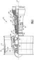
Figure 1 shows a gas turbine engine. -
Figure 2A shows a scavenge tube mounted within a case. -
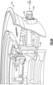
Figure 2B shows a detail of the scavenge tube. -
Figure 3A shows a tool. -
Figure 3B is another view of theFigure 3A tool. -
Figure 3C shows a detail of the tool in a unlocked position. -
Figure 3D shows the tool having been moved to the locked position. -
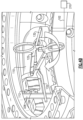
Figure 4A shows the tool as it sits on a scavenge tube. -
Figure 4B shows a subsequent step in a method. -
Figure 4C shows a final assembly step. -
Figure 1 schematically illustrates agas turbine engine 20. Thegas turbine engine 20 is disclosed herein as a two-spool turbofan that generally incorporates afan section 22, acompressor section 24, a combustor section 26 and aturbine section 28. Alternative engines might include an augmentor section (not shown) among other systems or features. Thefan section 22 drives air along a bypass flow path B in a bypass duct defined within anacelle 15, while thecompressor section 24 drives air along a core flow path C for compression and communication into the combustor section 26 then expansion through theturbine section 28. Although depicted as a two-spool turbofan gas turbine engine in the disclosed non-limiting embodiment, it should be understood that the concepts described herein are not limited to use with two-spool turbofans as the teachings may be applied to other types of turbine engines including three-spool architectures. - The
exemplary engine 20 generally includes alow speed spool 30 and ahigh speed spool 32 mounted for rotation about an engine central longitudinal axis A relative to an enginestatic structure 36 viaseveral bearing systems 38. It should be understood thatvarious bearing systems 38 at various locations may alternatively or additionally be provided, and the location ofbearing systems 38 may be varied as appropriate to the application. - The
low speed spool 30 generally includes aninner shaft 40 that interconnects afan 42, a first (or low) pressure compressor 44 and a first (or low)pressure turbine 46. Theinner shaft 40 is connected to thefan 42 through a speed change mechanism, which in exemplarygas turbine engine 20 is illustrated as a gearedarchitecture 48 to drive thefan 42 at a lower speed than thelow speed spool 30. Thehigh speed spool 32 includes anouter shaft 50 that interconnects a second (or high)pressure compressor 52 and a second (or high)pressure turbine 54. Acombustor 56 is arranged inexemplary gas turbine 20 between thehigh pressure compressor 52 and thehigh pressure turbine 54. Amid-turbine frame 57 of the enginestatic structure 36 is arranged generally between thehigh pressure turbine 54 and thelow pressure turbine 46. Themid-turbine frame 57 further supports bearingsystems 38 in theturbine section 28. Theinner shaft 40 and theouter shaft 50 are concentric and rotate viabearing systems 38 about the engine central longitudinal axis A which is collinear with their longitudinal axes. - The core airflow is compressed by the low pressure compressor 44 then the
high pressure compressor 52, mixed and burned with fuel in thecombustor 56, then expanded over thehigh pressure turbine 54 andlow pressure turbine 46. Themid-turbine frame 57 includesairfoils 59 which are in the core airflow path C. Theturbines low speed spool 30 andhigh speed spool 32 in response to the expansion. It will be appreciated that each of the positions of thefan section 22,compressor section 24, combustor section 26,turbine section 28, and fandrive gear system 48 may be varied. For example,gear system 48 may be located aft of combustor section 26 or even aft ofturbine section 28, andfan section 22 may be positioned forward or aft of the location ofgear system 48. - The
engine 20 in one example is a high-bypass geared aircraft engine. In a further example, theengine 20 bypass ratio is greater than about six, with an example embodiment being greater than about ten, the gearedarchitecture 48 is an epicyclic gear train, such as a planetary gear system or other gear system, with a gear reduction ratio of greater than about 2.3 and thelow pressure turbine 46 has a pressure ratio that is greater than about five. In one disclosed embodiment, theengine 20 bypass ratio is greater than about ten, the fan diameter is significantly larger than that of the low pressure compressor 44, and thelow pressure turbine 46 has a pressure ratio that is greater than about five.Low pressure turbine 46 pressure ratio is pressure measured prior to inlet oflow pressure turbine 46 as related to the pressure at the outlet of thelow pressure turbine 46 prior to an exhaust nozzle. The gearedarchitecture 48 may be an epicycle gear train, such as a planetary gear system or other gear system, with a gear reduction ratio of greater than about 2.3:1. It should be understood, however, that the above parameters are only exemplary of one embodiment of a geared architecture engine and that the present invention is applicable to other gas turbine engines including direct drive turbofans. - A significant amount of thrust is provided by the bypass flow B due to the high bypass ratio. The
fan section 22 of theengine 20 is designed for a particular flight condition -- typically cruise at about 0.8 Mach and about 35,000 feet (10,668 meters). The flight condition of 0.8 Mach and 35,000 ft (10,668 meters), with the engine at its best fuel consumption - also known as "bucket cruise Thrust Specific Fuel Consumption ('TSFC')" - is the industry standard parameter of lbm of fuel being burned divided by lbf of thrust the engine produces at that minimum point. "Low fan pressure ratio" is the pressure ratio across the fan blade alone, without a Fan Exit Guide Vane ("FEGV") system. The low fan pressure ratio as disclosed herein according to one non-limiting embodiment is less than about 1.45. "Low corrected fan tip speed" is the actual fan tip speed in ft/sec divided by an industry standard temperature correction of [(Tram °R) / (518.7 °R)]0.5 (where °R = K x 9/5). The "Low corrected fan tip speed" as disclosed herein according to one non-limiting embodiment is less than about 1150 ft / second (350.5 meters/second). -
Figure 2A shows a turbineintermediate case 100 which is mountable within the gas turbine engine ofFigure 1 . As shown, abearing support 101 may support shafts associated with the rotors in the turbine section. It is known to supply lubricant to various locations in the turbine intermediate case including the bearing area. It is also known to provide ascavenge tube 102 to return the lubricant back to a lubricant sump. The scavenge tube extends into a bracket orhousing 106 and seals 104 are located at the area. Internal to thebearing support 101 and thehousing 106, thescavenge tube 102 communicates into a scavenge tube end 110 having aninlet 112. Thetube 102 has aportion 109 extending through anotherhousing 108, which may also include seals. This is returned to an oil sump located at some remote location. - As is clear from
Figure 2A , theinlet 112 is spaced quite closely to acrossover tube 328 which has a distinct function. Thus, space is limited adjacent theinlet 112. -
Figure 2B shows thetube 102 removed from thehousing 106, and illustrates the location of aseal 104. It would be desirable to test thescavenge tube 102/110 for leakage without having to disassemble the system. Thus, a pressure test would be desirable. However, to perform a pressure test, one must seal theinlet 112 and apply pressure to a remote end of thetube 102. While a seal is shown, as mentioned above there are other potential leakage locations to test. -
Figure 3A shows atool 120 haveforceps 122 with aratchet clamping lock 124.Semi-circular grippers tube 110, as disclosed below. Aplug 128 will move into theinlet 112. Theplug 128 is mounted into anend 130. Anactuation structure 134 is actuated by alever 132 to cause theplug 128 to move in an axial direction. -
Figure 3B is a crosscut view and shows theactuation structure 134. When thelever 132 is pivoted, it causes theactuation structure 134 to move aportion 140 on anend 142 of anactuator link 136.Actuator link 136 extends to themount 130 which receives aball mount 129 associated with theplug 128. Awasher 144 is provided to transmit force to grippervanes 127. Anoil ring seal 300 and achamfer 301 may be included. - As shown in
Figure 3C , thelever 132 and theactuation structure 134 is in the non-actuated position. -
Figure 3D shows thelever 132 having been pivoted clockwise in this view with the actuation structure also pivoting and providing a force against theforceps 122 to draw theseal 128 to the right, in this view. Apin 312 locks thelever 132 in this lock or sealing position. - As can be appreciated from
Figures 3B-3D ,pin 600 extends throughend 142. When thelever 132 is pivoted to theFigure 3D position one can see the pin is moved to the right.Seal 128 is then pulled to the right. -
Figure 4A shows a test position for thetool 120. Initially the seal may be brought under thetube 110 and then upwardly into theinlet 112. Then, theforceps 122 could be locked. Theforceps 122 have the clamp portions (or "forceps locks") 126 and 127 locked on to an outerperipheral surface 111 of thetube 110 adjacent an end nearinlet 112. Theplug 128 is received within theinlet 112 sealing the inlet. Although this structure is all close to thetube 110, there is adequate room to mount thetool 120. -
Figure 4B is a distinct view and shows theplug 128 in theinlet 112. Thelever 132 is moved to the lock position to cause theplug 128 to be moved into the inlet. -
Figure 4C shows apin 312 inserted in ahole 310 to locklever 132 at the lock position during testing. - As shown in
Figures 4A and4B schematically, thetube 102 is connected to apressure source 210. Once the tool has sealed theinlet 112, pressure can be applied on thetube 102 and the pressure may be monitored. If the pressure drops more than a predetermining amount in a particular period of time, then a leak may be identified. Once the test is over, the tool is easily removed and the engine may be either repaired or moved back to service, as appropriate. - A method of providing a pressure test on a tube to identify leakage includes the steps of mounting a clamp on a tube adjacent to an end and such that a plug which is part of the tool is positioned to plug an opening in the inlet. The method also actuates the tool to cause the plug to provide a fluid tight seal in the inlet. A source of pressure is applied to the tube. The pressure within the tube is monitored, and a leak is identified should the pressure drop more than a predetermined amount in a particular period of time.
- Although an embodiment of this invention has been disclosed, a worker of ordinary skill in this art would recognize that certain modifications would come within the scope of the invention as defined in the appended claims.
Claims (6)
- A method of providing a pressure test on a tube to identify leakage;wherein said tube is a tube end (110) connected to a bearing support (101) and a scavenge tube (102) is connected to a portion of a housing (106), wherein said housing (106) is a turbine intermediate case (100) in a gas turbine engine (20), and wherein said scavenge tube (102) is in fluid communication with said tube end (110);the method including the steps of:(a) mounting a tool (120) including a clamp on a tube adjacent an end and such that a plug (128) which is part of said tool (120) is positioned to plug an inlet (112) into said tube, wherein said tool (120) includes forceps locks (126, 127), which lock on an outer peripheral surface (111) above of said tube end (110) prior to the movement of step (b);(b) actuating said tool (120) to cause said plug (128) to provide a fluid tight seal in the inlet (112), wherein a lever (132) on said tool (120) is pivoted to cause said plug (128) to be moved axially into said inlet (112); and(c) applying a source of pressure (210) to said tube, wherein the pressure source (210) is applied to a remote end of said scavenge tube (102) relative to said tube end (110), and monitoring the pressure within said tube, and identifying a leak should said pressure drop more than a predetermined amount in a particular period of time.
- The method as set forth in claim 1, wherein after said lever (132) is pivoted, a pin (312) is inserted to lock the lever (132) at the pivoted position.
- The method as set forth in any preceding claim, wherein said inlet (112) is positioned adjacent obstructions.
- The method as set forth in claim 3, wherein said obstructions include at least a crossover tube (328).
- The method as set forth in any preceding claim, wherein said tube is configured to return oil to an oil sump.
- The method as set forth in any preceding claim, wherein said method identifies a leaking seal, housing, tube, joints or connections.
Applications Claiming Priority (1)
| Application Number | Priority Date | Filing Date | Title |
|---|---|---|---|
| US16/361,279 US11022516B2 (en) | 2019-03-22 | 2019-03-22 | Tool for use in providing a seal on a tube end to allow a pressure test |
Publications (2)
| Publication Number | Publication Date |
|---|---|
| EP3712586A1 EP3712586A1 (en) | 2020-09-23 |
| EP3712586B1 true EP3712586B1 (en) | 2024-11-20 |
Family
ID=69953859
Family Applications (1)
| Application Number | Title | Priority Date | Filing Date |
|---|---|---|---|
| EP20164862.3A Active EP3712586B1 (en) | 2019-03-22 | 2020-03-23 | Plug for pressure testing and method of pressure testing |
Country Status (2)
| Country | Link |
|---|---|
| US (1) | US11022516B2 (en) |
| EP (1) | EP3712586B1 (en) |
Families Citing this family (2)
| Publication number | Priority date | Publication date | Assignee | Title |
|---|---|---|---|---|
| US11719120B2 (en) * | 2021-12-27 | 2023-08-08 | Pratt & Whitney Canada Corp. | Vacuum testing a seal within a gas turbine engine structure |
| US20250155312A1 (en) * | 2023-11-10 | 2025-05-15 | Rtx Corporation | Additive inflatable leak check bladder |
Citations (2)
| Publication number | Priority date | Publication date | Assignee | Title |
|---|---|---|---|---|
| US4152598A (en) * | 1975-12-23 | 1979-05-01 | Rolls-Royce (1971) Limited | Lubricant distribution determination by neutron radiography |
| DE202010014716U1 (en) * | 2010-10-26 | 2010-12-23 | Dagn, Josef | Device for sealing an opening in a neck |
Family Cites Families (8)
| Publication number | Priority date | Publication date | Assignee | Title |
|---|---|---|---|---|
| US3884070A (en) | 1971-04-12 | 1975-05-20 | Phillips Petroleum Co | Apparatus for testing conduit |
| US4046006A (en) * | 1975-07-09 | 1977-09-06 | Alex Dufrene | Tubing plug apparatus for performing down-hole pressure tests |
| DE3532609A1 (en) | 1985-09-12 | 1987-03-19 | Josef Dagn | Sealing apparatus for container openings, pipes and the like |
| DE20101526U1 (en) | 2001-01-30 | 2001-08-02 | Fedor Ulisch GmbH, 42855 Remscheid | Test plugs for density tests and leakage quantity measurements on gas-carrying pipes in a pipe network |
| US7168297B2 (en) | 2003-10-28 | 2007-01-30 | Environmental Systems Products Holdings Inc. | System and method for testing fuel tank integrity |
| US8006967B2 (en) | 2008-08-19 | 2011-08-30 | Silverbrook Research Pty Ltd | Cradle assembly for a pressure decay leak tester |
| US9089958B2 (en) * | 2011-07-01 | 2015-07-28 | Mil3 Inc. | Multi-functional tool for flexible pipe and related methods |
| EP3084180B1 (en) | 2013-12-16 | 2020-04-01 | United Technologies Corporation | Transfer bearing for geared turbofan |
-
2019
- 2019-03-22 US US16/361,279 patent/US11022516B2/en active Active
-
2020
- 2020-03-23 EP EP20164862.3A patent/EP3712586B1/en active Active
Patent Citations (2)
| Publication number | Priority date | Publication date | Assignee | Title |
|---|---|---|---|---|
| US4152598A (en) * | 1975-12-23 | 1979-05-01 | Rolls-Royce (1971) Limited | Lubricant distribution determination by neutron radiography |
| DE202010014716U1 (en) * | 2010-10-26 | 2010-12-23 | Dagn, Josef | Device for sealing an opening in a neck |
Also Published As
| Publication number | Publication date |
|---|---|
| US11022516B2 (en) | 2021-06-01 |
| EP3712586A1 (en) | 2020-09-23 |
| US20200300723A1 (en) | 2020-09-24 |
Similar Documents
| Publication | Publication Date | Title |
|---|---|---|
| EP3085899B1 (en) | Gas turbine engine mid turbine frame including a sealed torque box | |
| EP3000988A1 (en) | Fan drive gear system | |
| EP3632800A1 (en) | Fluid tube assembly for gas turbine engine | |
| EP3296519A1 (en) | Flowpath component for a gas turbine engine including a chordal seal | |
| US11111821B2 (en) | Retention assembly for gas turbine engine | |
| EP3045665A1 (en) | Gas turbine engine mid-turbine frame tie rod arrangement | |
| EP3712586A1 (en) | Plug for pressure testing and method of pressure testing | |
| EP3048283B1 (en) | A conduit assembly and method of utilization | |
| US11149640B2 (en) | Circular seal outer diameter seal effectiveness testing tool | |
| EP3502455B1 (en) | Bleed valve system | |
| US11649729B2 (en) | Anti-vortex tube retaining ring and bore basket | |
| US11181004B2 (en) | Confinement of a rope seal about a passage using a backing plate | |
| US11624294B1 (en) | Restraining plug | |
| EP3859140B1 (en) | Nozzle-to-engine mount reinforcement through which mounting fasteners are visible | |
| EP2985425B1 (en) | Gas turbine engine cooling fluid metering system | |
| EP3611358B1 (en) | Bleed valve actuation system | |
| EP3421720B1 (en) | Turbine shaft and corresponding air transfer system | |
| EP4365410A2 (en) | Multi-purpose anti-rotation lock pin | |
| EP4202192B1 (en) | Restraining plug | |
| US12228043B1 (en) | Carbon seal covers | |
| US20250154877A1 (en) | Slider seal of gas turbine engine | |
| EP3626935A1 (en) | Fan drive gear system |
Legal Events
| Date | Code | Title | Description |
|---|---|---|---|
| PUAI | Public reference made under article 153(3) epc to a published international application that has entered the european phase |
Free format text: ORIGINAL CODE: 0009012 |
|
| STAA | Information on the status of an ep patent application or granted ep patent |
Free format text: STATUS: THE APPLICATION HAS BEEN PUBLISHED |
|
| AK | Designated contracting states |
Kind code of ref document: A1 Designated state(s): AL AT BE BG CH CY CZ DE DK EE ES FI FR GB GR HR HU IE IS IT LI LT LU LV MC MK MT NL NO PL PT RO RS SE SI SK SM TR |
|
| AX | Request for extension of the european patent |
Extension state: BA ME |
|
| RAP1 | Party data changed (applicant data changed or rights of an application transferred) |
Owner name: RAYTHEON TECHNOLOGIES CORPORATION |
|
| STAA | Information on the status of an ep patent application or granted ep patent |
Free format text: STATUS: REQUEST FOR EXAMINATION WAS MADE |
|
| 17P | Request for examination filed |
Effective date: 20210323 |
|
| RBV | Designated contracting states (corrected) |
Designated state(s): AL AT BE BG CH CY CZ DE DK EE ES FI FR GB GR HR HU IE IS IT LI LT LU LV MC MK MT NL NO PL PT RO RS SE SI SK SM TR |
|
| STAA | Information on the status of an ep patent application or granted ep patent |
Free format text: STATUS: EXAMINATION IS IN PROGRESS |
|
| 17Q | First examination report despatched |
Effective date: 20211216 |
|
| RAP3 | Party data changed (applicant data changed or rights of an application transferred) |
Owner name: RTX CORPORATION |
|
| GRAP | Despatch of communication of intention to grant a patent |
Free format text: ORIGINAL CODE: EPIDOSNIGR1 |
|
| STAA | Information on the status of an ep patent application or granted ep patent |
Free format text: STATUS: GRANT OF PATENT IS INTENDED |
|
| INTG | Intention to grant announced |
Effective date: 20240618 |
|
| GRAS | Grant fee paid |
Free format text: ORIGINAL CODE: EPIDOSNIGR3 |
|
| GRAA | (expected) grant |
Free format text: ORIGINAL CODE: 0009210 |
|
| STAA | Information on the status of an ep patent application or granted ep patent |
Free format text: STATUS: THE PATENT HAS BEEN GRANTED |
|
| AK | Designated contracting states |
Kind code of ref document: B1 Designated state(s): AL AT BE BG CH CY CZ DE DK EE ES FI FR GB GR HR HU IE IS IT LI LT LU LV MC MK MT NL NO PL PT RO RS SE SI SK SM TR |
|
| REG | Reference to a national code |
Ref country code: GB Ref legal event code: FG4D |
|
| REG | Reference to a national code |
Ref country code: CH Ref legal event code: EP |
|
| REG | Reference to a national code |
Ref country code: DE Ref legal event code: R096 Ref document number: 602020041535 Country of ref document: DE |
|
| REG | Reference to a national code |
Ref country code: IE Ref legal event code: FG4D |
|
| REG | Reference to a national code |
Ref country code: LT Ref legal event code: MG9D |
|
| REG | Reference to a national code |
Ref country code: NL Ref legal event code: MP Effective date: 20241120 |
|
| PG25 | Lapsed in a contracting state [announced via postgrant information from national office to epo] |
Ref country code: HR Free format text: LAPSE BECAUSE OF FAILURE TO SUBMIT A TRANSLATION OF THE DESCRIPTION OR TO PAY THE FEE WITHIN THE PRESCRIBED TIME-LIMIT Effective date: 20241120 Ref country code: IS Free format text: LAPSE BECAUSE OF FAILURE TO SUBMIT A TRANSLATION OF THE DESCRIPTION OR TO PAY THE FEE WITHIN THE PRESCRIBED TIME-LIMIT Effective date: 20250320 Ref country code: PT Free format text: LAPSE BECAUSE OF FAILURE TO SUBMIT A TRANSLATION OF THE DESCRIPTION OR TO PAY THE FEE WITHIN THE PRESCRIBED TIME-LIMIT Effective date: 20250320 |
|
| PG25 | Lapsed in a contracting state [announced via postgrant information from national office to epo] |
Ref country code: FI Free format text: LAPSE BECAUSE OF FAILURE TO SUBMIT A TRANSLATION OF THE DESCRIPTION OR TO PAY THE FEE WITHIN THE PRESCRIBED TIME-LIMIT Effective date: 20241120 Ref country code: NL Free format text: LAPSE BECAUSE OF FAILURE TO SUBMIT A TRANSLATION OF THE DESCRIPTION OR TO PAY THE FEE WITHIN THE PRESCRIBED TIME-LIMIT Effective date: 20241120 |
|
| REG | Reference to a national code |
Ref country code: AT Ref legal event code: MK05 Ref document number: 1743963 Country of ref document: AT Kind code of ref document: T Effective date: 20241120 |
|
| PG25 | Lapsed in a contracting state [announced via postgrant information from national office to epo] |
Ref country code: BG Free format text: LAPSE BECAUSE OF FAILURE TO SUBMIT A TRANSLATION OF THE DESCRIPTION OR TO PAY THE FEE WITHIN THE PRESCRIBED TIME-LIMIT Effective date: 20241120 |
|
| PG25 | Lapsed in a contracting state [announced via postgrant information from national office to epo] |
Ref country code: ES Free format text: LAPSE BECAUSE OF FAILURE TO SUBMIT A TRANSLATION OF THE DESCRIPTION OR TO PAY THE FEE WITHIN THE PRESCRIBED TIME-LIMIT Effective date: 20241120 |
|
| PG25 | Lapsed in a contracting state [announced via postgrant information from national office to epo] |
Ref country code: NO Free format text: LAPSE BECAUSE OF FAILURE TO SUBMIT A TRANSLATION OF THE DESCRIPTION OR TO PAY THE FEE WITHIN THE PRESCRIBED TIME-LIMIT Effective date: 20250220 |
|
| PG25 | Lapsed in a contracting state [announced via postgrant information from national office to epo] |
Ref country code: LV Free format text: LAPSE BECAUSE OF FAILURE TO SUBMIT A TRANSLATION OF THE DESCRIPTION OR TO PAY THE FEE WITHIN THE PRESCRIBED TIME-LIMIT Effective date: 20241120 Ref country code: AT Free format text: LAPSE BECAUSE OF FAILURE TO SUBMIT A TRANSLATION OF THE DESCRIPTION OR TO PAY THE FEE WITHIN THE PRESCRIBED TIME-LIMIT Effective date: 20241120 Ref country code: GR Free format text: LAPSE BECAUSE OF FAILURE TO SUBMIT A TRANSLATION OF THE DESCRIPTION OR TO PAY THE FEE WITHIN THE PRESCRIBED TIME-LIMIT Effective date: 20250221 |
|
| PG25 | Lapsed in a contracting state [announced via postgrant information from national office to epo] |
Ref country code: PL Free format text: LAPSE BECAUSE OF FAILURE TO SUBMIT A TRANSLATION OF THE DESCRIPTION OR TO PAY THE FEE WITHIN THE PRESCRIBED TIME-LIMIT Effective date: 20241120 |
|
| PG25 | Lapsed in a contracting state [announced via postgrant information from national office to epo] |
Ref country code: RS Free format text: LAPSE BECAUSE OF FAILURE TO SUBMIT A TRANSLATION OF THE DESCRIPTION OR TO PAY THE FEE WITHIN THE PRESCRIBED TIME-LIMIT Effective date: 20250220 |
|
| PG25 | Lapsed in a contracting state [announced via postgrant information from national office to epo] |
Ref country code: SM Free format text: LAPSE BECAUSE OF FAILURE TO SUBMIT A TRANSLATION OF THE DESCRIPTION OR TO PAY THE FEE WITHIN THE PRESCRIBED TIME-LIMIT Effective date: 20241120 |
|
| PG25 | Lapsed in a contracting state [announced via postgrant information from national office to epo] |
Ref country code: DK Free format text: LAPSE BECAUSE OF FAILURE TO SUBMIT A TRANSLATION OF THE DESCRIPTION OR TO PAY THE FEE WITHIN THE PRESCRIBED TIME-LIMIT Effective date: 20241120 |
|
| PG25 | Lapsed in a contracting state [announced via postgrant information from national office to epo] |
Ref country code: EE Free format text: LAPSE BECAUSE OF FAILURE TO SUBMIT A TRANSLATION OF THE DESCRIPTION OR TO PAY THE FEE WITHIN THE PRESCRIBED TIME-LIMIT Effective date: 20241120 |
|
| PG25 | Lapsed in a contracting state [announced via postgrant information from national office to epo] |
Ref country code: RO Free format text: LAPSE BECAUSE OF FAILURE TO SUBMIT A TRANSLATION OF THE DESCRIPTION OR TO PAY THE FEE WITHIN THE PRESCRIBED TIME-LIMIT Effective date: 20241120 |
|
| PG25 | Lapsed in a contracting state [announced via postgrant information from national office to epo] |
Ref country code: SK Free format text: LAPSE BECAUSE OF FAILURE TO SUBMIT A TRANSLATION OF THE DESCRIPTION OR TO PAY THE FEE WITHIN THE PRESCRIBED TIME-LIMIT Effective date: 20241120 |
|
| PG25 | Lapsed in a contracting state [announced via postgrant information from national office to epo] |
Ref country code: CZ Free format text: LAPSE BECAUSE OF FAILURE TO SUBMIT A TRANSLATION OF THE DESCRIPTION OR TO PAY THE FEE WITHIN THE PRESCRIBED TIME-LIMIT Effective date: 20241120 |
|
| PG25 | Lapsed in a contracting state [announced via postgrant information from national office to epo] |
Ref country code: IT Free format text: LAPSE BECAUSE OF FAILURE TO SUBMIT A TRANSLATION OF THE DESCRIPTION OR TO PAY THE FEE WITHIN THE PRESCRIBED TIME-LIMIT Effective date: 20241120 |
|
| REG | Reference to a national code |
Ref country code: DE Ref legal event code: R097 Ref document number: 602020041535 Country of ref document: DE |
|
| PG25 | Lapsed in a contracting state [announced via postgrant information from national office to epo] |
Ref country code: SE Free format text: LAPSE BECAUSE OF FAILURE TO SUBMIT A TRANSLATION OF THE DESCRIPTION OR TO PAY THE FEE WITHIN THE PRESCRIBED TIME-LIMIT Effective date: 20241120 |
|
| PLBE | No opposition filed within time limit |
Free format text: ORIGINAL CODE: 0009261 |
|
| STAA | Information on the status of an ep patent application or granted ep patent |
Free format text: STATUS: NO OPPOSITION FILED WITHIN TIME LIMIT |
|
| PG25 | Lapsed in a contracting state [announced via postgrant information from national office to epo] |
Ref country code: MC Free format text: LAPSE BECAUSE OF FAILURE TO SUBMIT A TRANSLATION OF THE DESCRIPTION OR TO PAY THE FEE WITHIN THE PRESCRIBED TIME-LIMIT Effective date: 20241120 |
|
| 26N | No opposition filed |
Effective date: 20250821 |
|
| REG | Reference to a national code |
Ref country code: CH Ref legal event code: H13 Free format text: ST27 STATUS EVENT CODE: U-0-0-H10-H13 (AS PROVIDED BY THE NATIONAL OFFICE) Effective date: 20251023 |
|
| PG25 | Lapsed in a contracting state [announced via postgrant information from national office to epo] |
Ref country code: LU Free format text: LAPSE BECAUSE OF NON-PAYMENT OF DUE FEES Effective date: 20250323 |
|
| REG | Reference to a national code |
Ref country code: BE Ref legal event code: MM Effective date: 20250331 |
|
| PG25 | Lapsed in a contracting state [announced via postgrant information from national office to epo] |
Ref country code: BE Free format text: LAPSE BECAUSE OF NON-PAYMENT OF DUE FEES Effective date: 20250331 |
|
| PG25 | Lapsed in a contracting state [announced via postgrant information from national office to epo] |
Ref country code: CH Free format text: LAPSE BECAUSE OF NON-PAYMENT OF DUE FEES Effective date: 20250331 |
|
| PG25 | Lapsed in a contracting state [announced via postgrant information from national office to epo] |
Ref country code: IE Free format text: LAPSE BECAUSE OF NON-PAYMENT OF DUE FEES Effective date: 20250323 |
|
| PGFP | Annual fee paid to national office [announced via postgrant information from national office to epo] |
Ref country code: GB Payment date: 20260219 Year of fee payment: 7 |
|
| PGFP | Annual fee paid to national office [announced via postgrant information from national office to epo] |
Ref country code: DE Payment date: 20260219 Year of fee payment: 7 |
|
| PGFP | Annual fee paid to national office [announced via postgrant information from national office to epo] |
Ref country code: FR Payment date: 20260220 Year of fee payment: 7 |