EP3712516A1 - Wall-mounted indoor air conditioner unit - Google Patents
Wall-mounted indoor air conditioner unit Download PDFInfo
- Publication number
- EP3712516A1 EP3712516A1 EP19798515.3A EP19798515A EP3712516A1 EP 3712516 A1 EP3712516 A1 EP 3712516A1 EP 19798515 A EP19798515 A EP 19798515A EP 3712516 A1 EP3712516 A1 EP 3712516A1
- Authority
- EP
- European Patent Office
- Prior art keywords
- buckle
- assembly
- wall
- connecting member
- air conditioner
- Prior art date
- Legal status (The legal status is an assumption and is not a legal conclusion. Google has not performed a legal analysis and makes no representation as to the accuracy of the status listed.)
- Granted
Links
Images





Classifications
-
- F—MECHANICAL ENGINEERING; LIGHTING; HEATING; WEAPONS; BLASTING
- F24—HEATING; RANGES; VENTILATING
- F24F—AIR-CONDITIONING; AIR-HUMIDIFICATION; VENTILATION; USE OF AIR CURRENTS FOR SCREENING
- F24F1/00—Room units for air-conditioning, e.g. separate or self-contained units or units receiving primary air from a central station
- F24F1/0007—Indoor units, e.g. fan coil units
- F24F1/0071—Indoor units, e.g. fan coil units with means for purifying supplied air
- F24F1/0073—Indoor units, e.g. fan coil units with means for purifying supplied air characterised by the mounting or arrangement of filters
-
- F—MECHANICAL ENGINEERING; LIGHTING; HEATING; WEAPONS; BLASTING
- F24—HEATING; RANGES; VENTILATING
- F24F—AIR-CONDITIONING; AIR-HUMIDIFICATION; VENTILATION; USE OF AIR CURRENTS FOR SCREENING
- F24F1/00—Room units for air-conditioning, e.g. separate or self-contained units or units receiving primary air from a central station
- F24F1/0007—Indoor units, e.g. fan coil units
- F24F1/0043—Indoor units, e.g. fan coil units characterised by mounting arrangements
- F24F1/0057—Indoor units, e.g. fan coil units characterised by mounting arrangements mounted in or on a wall
-
- F—MECHANICAL ENGINEERING; LIGHTING; HEATING; WEAPONS; BLASTING
- F24—HEATING; RANGES; VENTILATING
- F24F—AIR-CONDITIONING; AIR-HUMIDIFICATION; VENTILATION; USE OF AIR CURRENTS FOR SCREENING
- F24F2221/00—Details or features not otherwise provided for
- F24F2221/22—Cleaning ducts or apparatus
Definitions
- the present application relates to the field of air conditioning technology, and in particular to an indoor unit of a wall-mounted air conditioner.
- a cleaning assembly may be provided on one side of an indoor unit of a wall-mounted air conditioner for automatically washing the screen.
- the cleaning assembly and the screen assembly are usually mounted on the chassis, and the relative position between them may be adjusted to mesh the gear of the cleaning assembly with the screen, so that the screen may be driven to move for the washing process.
- the main purpose of the present application is to provide an indoor unit of a wall-mounted air conditioner, aiming at solving the technical problem of poor transmission reliability of a screen during the washing process.
- an indoor unit of a wall-mounted air conditioner including:
- the fastening structure is a detachable structure.
- the fastening structure includes:
- the screen assembly includes:
- a second connecting member extends downwardly from a front portion of the grille assembly; the first buckle structure further includes:
- the screen assembly includes:
- the chassis includes:
- a fourth connecting member is protruded from the cleaning box of the cleaning assembly and extended away from the other end of the screen assembly; and where the second threaded structure includes:
- the fourth connecting member is integrally formed on a rear side edge of the third connecting member.
- a gear of the cleaning assembly is engaged with an engaging member of a screen of the screen assembly, where the engaging member is a rack; or the engaging member defines at least one engaging hole.
- the indoor unit of the wall-mounted air conditioner further includes:
- the cleaning assembly and the screen assembly are fixedly connected by the fastening structure, thereby improving the connection stability between the cleaning assembly and the screen assembly and further improving the engaging stability of the gear of the cleaning assembly and the screen; so that the defects such as misalignment, jamming, abnormal noise, etc. of the engaging transmission between the gear and the screen may be avoided in the process of washing, thereby improving the transmission reliability of the screen in the washing process.
- Reference numeral Name Reference numeral Name 100 Indoor unit 223 First threaded hole 10 Chassis 225 Bottom bracket 11 Bottom wall 226 Screen bracket 111 Accommodating space 227 Air-inlet grille 12 Rear side wall 30 Cleaning assembly 121 Threaded hole column 31 Cleaning box 122 Second threaded hole 311 First buckle 123 Third buckle hole 312 Second buckle 20 Screen assembly 313 Third connecting member 21 Screen 3131 First via hole 211 Engaging member 314 Fourth connecting member 22 Grille assembly 3141 Second via hole 221 First connecting member 32 Roller brush assembly 2211 First buckle hole 321 Roller brush 222 Second connecting member 322 Gear 2221 Second buckle hole 40 Face frame
- first if there is a description relating to "first”, “second”, etc. in the embodiments of the present disclosure, it is used for descriptive purposes only, and cannot be understood to indicate or imply its relative importance or to imply the number of technical features indicated. Thus, features defining “first” or “second” may include at least one of the features, either explicitly or implicitly.
- the meaning of "and/or” appearing throughout the text includes three parallel solutions, taking "A and/or B" as an example, it includes the A solution, or the B solution, or the solution in which both A and B are simultaneously satisfied.
- the present application provides an indoor unit of a wall-mounted air conditioner.
- the indoor unit 100 of the wall-mounted air conditioner includes:
- the fastening structure is a structure that securely connects the cleaning assembly 30 and the screen assembly 20, which is configured to improve the connection stability between the cleaning assembly 30 and the screen assembly 20.
- the cleaning assembly 30 and the screen assembly 20 are connected by the fastening structure, and a gear 322 of the cleaning assembly 30 and a screen 21 of the screen assembly 20 are simultaneously engaged (where the screen 21 is provided with an engaging member 211 configured for engaging with the gear 322); then, the cleaning assembly 30 together with the screen assembly 20 are mounted on the chassis 10.
- the cleaning assembly 30 and the screen assembly 20 are fixedly connected by the fastening structure, thereby improving the connection stability between the cleaning assembly 30 and the screen assembly 20 and further improving the engaging stability of the gear 322 of the cleaning assembly 30 and the screen 21 of the screen assembly 20; so that the defects such as misalignment, jamming, abnormal noise, etc. of the engaging transmission between the gear 322 and the screen 21 may be avoided in the process of washing, thereby improving the transmission reliability of the screen 21 in the washing process.
- the cleaning assembly 30 and the screen assembly 20 are fixedly connected by the fastening structure, thereby improving the connection stability between the cleaning assembly 30 and the screen assembly 20 and further improving the engaging stability of the gear 322 of the cleaning assembly 30 and the screen 21; so that the defects such as misalignment, jamming, abnormal noise, etc. of the engaging transmission between the gear 322 and the screen 21 may be avoided in the process of washing, thereby improving the transmission reliability of the screen 21 in the washing process.
- the cleaning assembly 30 and the screen assembly 20 are fixedly connected by the fastening structure, so that loosening of the engaged gear 322 and the screen 21 due to changed relative position of the cleaning assembly 30 and the screen assembly 20 caused by shaking and/or collision during transportation may be avoided.
- the assembly sequence of the indoor unit 100 of the wall-mounted air conditioner is: the cleaning assembly 30 and the screen assembly 20 are first fixedly connected by the fastening structure, and then the cleaning assembly 30 together with the screen assembly 20 are mounted on the chassis 10.
- the above assembly sequence is very convenient for checking the connection points on the production line.
- the fastening structure may include one or more of a snap structure, a threaded structure, a pin connection structure, a welded connection structure, etc.
- the fastening structure will be exemplified below, and it will be understood that many fastening structures are readily apparent to those skilled in the art on the basis of the following examples.
- the fastening structure is a detachable structure. As such, inspection, repair, replacement, etc. of the cleaning assembly 30 and/or the screen assembly 20 may be facilitated.
- the screen assembly 20 includes a screen 21 and a grille assembly 22.
- the cleaning assembly 30 includes a cleaning box 31 and a roll brush assembly 32 mounted on the cleaning box 31, and the gear 322 is a part of the roller brush assembly 32.
- the screen 21 is provided with an engaging member 211 for engaging with the gear 322.
- the fastening structure connects the cleaning box 31 and the grille assembly 22.
- the grille assembly 22 is substantially rectangular.
- the fastening structure includes a first buckle structure and a first threaded structure.
- the combination of the buckle structure and the threaded structure to secure the cleaning assembly 30 and the screen assembly 20 not only facilitates positioning during assembly, but also improves the stability of the connection between the cleaning assembly 30 and the screen assembly 20.
- the fastening structure may also include a first buckle structure only or a first threaded structure only.
- the cleaning box 31 is disposed below the grille assembly 22, and a first connecting member 221 extends downwardly from one end of the grille assembly 22.
- the first buckle structure includes a first buckle hole 2211 defined in the first connecting member 221 and a first buckle 311 protruded from the cleaning box 31.
- the first buckle 311 is adaptively engaged in the first buckle hole 2211.
- the first buckle 311 is disposed in an outer side of the cleaning box 31.
- the cleaning box 31 is substantially rectangular.
- the first buckle 311 is disposed in a left side of the cleaning box 31.
- the end of the grille assembly 22 may be constrained and connected to the left lateral side of the cleaning box 31.
- the first buckle 311 may also be disposed in the first connecting member 221, and correspondingly, the first buckle hole 2211 may be defined in the cleaning box 31.
- the first buckle structure includes the first buckle hole 2211 defined in the cleaning box 31, and the first buckle 311 protruded from the first connecting member 221, where the first buckle 311 is adaptively engaged in the first buckle hole 2211.
- the first connecting member 221 may be provided in a plate shape. As such, the structure and manufacturing process of the first connecting member 221 may be simplified.
- a side surface of the first buckle 311 toward the first buckle hole 2211 is obliquely extended to guide the engagement between the first connecting member 221 and the cleaning box 31.
- each first connecting member 221 is provided at intervals along a front-rear direction, and each first connecting member 221 defines the first buckle hole 2211 respectively, and two of the first buckles 311 are provided accordingly. As such, the connection strength and the connection stability may be improved.
- a second connecting member 222 extends downwardly from a front portion of the grille assembly 22.
- the first buckle structure further includes a second buckle hole 2221 defined in the second connecting member 222 and a second buckle 312 protruded from the cleaning box 31.
- the second buckle 312 is adaptively engaged in the second buckle hole 2221.
- the second buckle 312 is disposed in an outer side of the cleaning box 31.
- the second buckle 312 is disposed in a front side of the cleaning box 31.
- the front portion of the grille assembly 22 may be constrained and connected with the front lateral side of the cleaning box 31.
- the second buckle 312 may also be disposed in the second connecting member 222, and correspondingly, the second buckle hole 2221 is defined in the cleaning box 31.
- the first buckle structure further includes the second buckle hole 2221 defined in the cleaning box 31, and the second buckle 312 protruded from the second connecting member 222, where the second buckle 312 is adaptively engaged in the second buckle hole 2221.
- the second connecting member 222 may be provided in a plate shape. As such, the structure and manufacturing process of the second connecting member 222 may be simplified.
- a side surface of the second buckle 311 toward the second buckle hole 2211 is obliquely extended to further guide the engagement between the first connecting member 221 and the cleaning box 31.
- each second connecting member 222 defines a second buckle hole 2221 respectively, and two of the second buckle 312 are provided accordingly. As such, the connection strength and the connection stability may be improved.
- first connecting member 221 extends downwardly from the end of the grille assembly 22, and the first buckle hole 2211 is defined in the first connecting member 221 to be engaged with the first buckle 311 disposed in the cleaning box 31, so that the end of the grille assembly 22 and the left lateral side of the cleaning box may be constrained and connected.
- second connecting member 222 extends downwardly from the front portion of the grille assembly 22, and the second buckle hole 2221 is defined in the second connecting member to be engaged with the second buckle 312 disposed in the cleaning box, so that the front portion of the grille assembly 11 and the front lateral side of the cleaning box 31 may be constrained and connected. As such, the cleaning box 31 and the grille assembly 22 may be fastened.
- first buckle structure may also be set in other structural forms according to the first buckle structure mentioned above, which will not be detailed here.
- a third connecting member 313 extends upwardly from an edge of an opening of the cleaning box 31, where the first threaded structure includes a first locking screw (not shown), and the first locking screw penetrates the third connecting member 313 and is threaded with one end of the grille assembly 22, so as to connect the cleaning box 31 and the grille assembly 22.
- the first threaded structure further includes a first via hole 3131 defined in the third connecting member 313, and a first threaded hole 223 defined in an end surface of the grille assembly 22, where the first locking screw penetrates the first via hole 3131 and is threaded to the first threaded hole 223.
- an end surface where the first threaded hole 223 located is an end surface of an end where the first connecting member 221 located, and the third connecting member 313 is disposed on a left lateral side of the cleaning box 31.
- the strength of the connection between the cleaning box 31 and the grille assembly 22 may be further enhanced to further improve the stability of the connection between the cleaning assembly 30 and the screen assembly 20.
- the third connecting member 313 is disposed on a rear side of the edge of the opening of the cleaning box 31, and the first threaded hole 223 is defined in a rear side of the end face.
- first via hole 3131 may be a threaded hole. As such, the connection ability of the first threaded structure may be improved, so as to improve the connection stability between the cleaning box 31 and the grille assembly 22.
- first locking screw may also be replaced by a bolt or the like.
- first threaded structure may also be set in other structural forms according to the first threaded structure mentioned above, which will not be detailed here.
- the chassis 10 includes a bottom wall 11 and a rear side wall 12 connected to a rear side of the bottom wall 11.
- the bottom wall 11 and the rear side wall 12 may be integrally formed.
- the bottom wall 11 defines an accommodating space 111, and a lower portion of the cleaning assembly 30 is mounted in the accommodating space 111.
- a lower portion of the cleaning box 31 is mounted in the accommodating space 111.
- a lower portion of the cleaning assembly 30 may be restrained to ensure mounting stability between the cleaning assembly 30 and the screen assembly 20 on the chassis 10.
- two limit plates (not labeled) are provided at intervals on the bottom wall 11 in the length direction of the chassis 10 (namely the left-right direction in FIG. 10 ), and the two limit plates and the rear side walls 12 are enclosed to define the accommodating space 111 cooperatively.
- the structure of the accommodating space 111 may be simplified.
- the accommodating space 111 may also be set to other structural forms.
- an upper portion of the cleaning assembly 30 is connected with the rear side wall 12 by a second threaded structure, and/or the screen assembly 20 is connected with the rear side wall 12 by a second buckle structure.
- an upper portion of the cleaning box 31 is connected with the rear side wall 12 by a second threaded structure, and/or the grille assembly 22 is connected with the rear side wall 12 by a second buckle structure.
- an upper portion of the cleaning assembly 30 may be restrained to further ensure mounting stability between the cleaning assembly 30 and the screen assembly 20 on the chassis 10.
- an upper portion of the cleaning assembly 30 is connected with the rear side wall 12 by a second threaded structure, and the screen assembly 20 is connected with the rear side wall 12 by a second buckle structure.
- the mounting stability between the cleaning assembly 30 and the screen assembly 20 on the chassis 10 may be further improved and shaking during transportation may be avoided; but also the installation difficulty may be reduced during installation, since the upper portion of the cleaning assembly 30 may be firstly fixed through the second buckle structure and then the second threaded structure is installed.
- a fourth connecting member 314 is protruded from the cleaning box 31 and extended away from the other end of the screen assembly 20.
- the second threaded structure includes a second locking screw (not shown), and the second locking screw penetrates the fourth connecting member 314 and is threaded with the rear side wall 12.
- the fourth connecting member 314 is disposed on an outer lateral side of the cleaning box 31.
- the second threaded structure further includes a second via hole 3141 defined in the fourth connecting member 314 and a second threaded hole 122 defined in the rear side wall 12.
- the second locking screw penetrates the second via hole 3141 and is threaded into the second threaded hole 122.
- the upper portion of the cleaning box 31 may be mounted on the chassis 10.
- the fourth connecting member 314 is disposed on the left lateral side of the cleaning box 31.
- a threaded hole column 121 may be protruded from the rear side wall 12, and the second threaded hole 122 may be defined in the threaded hole column121.
- the second via hole 3141 may be a threaded hole. As such, the connection ability of the second threaded structure may be improved, so as to improve the connection stability between the cleaning box 31 and the chassis 10.
- the second locking screw may also be replaced by a bolt or the like.
- the second buckle structure includes a third buckle hole 123 defined in the rear side wall 12 and an inserting buckle protruded from the screen assembly 20 (not shown), and the inserting buckle is inserted into the third fastening buckle 123.
- the inserting buckle is disposed on an outer side of the screen assembly 20.
- the inserting buckle may be disposed on an outer side of the grille assembly 22.
- the screen assembly 20 may be mounted on the chassis 10 to improve mounting stability between the cleaning assembly 30 and the screen assembly 20 on the chassis 10.
- the inserting buckle may be disposed on a rear side of the grille assembly 22.
- the inserting buckle may also be disposed on the rear side wall 12, and correspondingly, the third buckle hole 123 may be defined in the screen assembly 20.
- the second buckle structure includes the third buckle hole 123 defined in the screen assembly 20 and the inserting buckle protruded from the rear side wall 12, and the inserting buckle is inserted into the third buckle hole 123.
- a plurality of the third buckle holes 123 are provided at intervals in the length direction of the chassis 10 (namely the left-right direction in FIG. 10 ), and a plurality of inserting buckles are correspondingly provided. As such, the mounting stability between the screen assembly 20 and the chassis 10 may be improved.
- the fourth connecting member 314 may be integrally formed on a rear side edge of the third connecting member 313. As such, the structure of the cleaning box 31 may be simplified.
- the engaging member 211 may be a rack. Thus, the engaging between the engaging member 211 and the gear 322 may be achieved.
- two of the racks may be provided and disposed on both sides of the screen 21 respectively.
- the engaging member 211 may also be set to other structural forms.
- the engaging member 211 defines at least one engaging hole for engaging with the gear 322.
- the indoor unit 100 of the wall-mounted air conditioner further includes a face frame 40 detachably mounted on the chassis 10, where the face frame 40 and the chassis 10 defines an accommodating cavity (not labeled) cooperatively, and the screen assembly 20 and the cleaning assembly 30 are mounted in the accommodating cavity.
- the face frame 40 is mounted after the cleaning assembly 30 and the screen assembly 20 are mounted on the chassis 10.
- the face frame 40 defines an air outlet corresponding to the screen assembly 20.
- the roller brush assembly 32 generally includes a roller brush 321 rotatably mounted at the opening of the cleaning box 31, and two gears 322 mounted on both ends of the roller brush 321.
- the roller brush 321 is used to clean the screen 21.
- the gear 322 is used to engage with the screen 21 to drive the screen 21 to move.
- the roller brush 321 includes a roller (not labeled) rotatably mounted on the cleaning box 31, and a brush (not labeled) wound on the roller, where the gear 322 is mounted on roller.
- the cleaning assembly 30 further includes a water-washing power assembly mounted on the cleaning box 31 for driving the roller to rotate.
- the grille assembly 22 defines two accommodating sliding slots (not shown) at intervals in the up-down direction.
- the screen 21 is slidably mounted in one of the accommodating sliding slots.
- the opening of the accommodating sliding slot is disposed adjacent to the roller brush assembly 32, and one end of the screen 21 protrudes from the opening to engage the engaging member 211 of the screen 21 with the gear 322.
- the gear 322 on the roller may be driven to rotate, so as to drive the gear 322 to drive the screen 21 to slide in the accommodating sliding slot. And one end of the screen 21 bypasses the roller 321 to enter the other accommodating sliding slot, the screen 21 is cleaned by the roller brush 321 during the process.
- the grille assembly 22 includes a bottom bracket 225, a screen bracket 226, and an air inlet grille 227 which are sequentially stacked, and the screen bracket 226 is disposed between the bottom bracket 225 and the air inlet grille 227.
- One of the accommodating sliding slot is defined between the air inlet grille 227 and the screen 21 bracket, and the other accommodating sliding slot is defined between the bottom bracket 225 and the screen bracket 226.
- the first connecting member 221 and the second connecting member 222 are both disposed on the air inlet grille 227.
Landscapes
- Engineering & Computer Science (AREA)
- Chemical & Material Sciences (AREA)
- Combustion & Propulsion (AREA)
- Mechanical Engineering (AREA)
- General Engineering & Computer Science (AREA)
- Air Filters, Heat-Exchange Apparatuses, And Housings Of Air-Conditioning Units (AREA)
Abstract
Description
- The present disclosure claims the priority of Chinese Patent Application with No.
201920179040.5 - The present application relates to the field of air conditioning technology, and in particular to an indoor unit of a wall-mounted air conditioner.
- A cleaning assembly may be provided on one side of an indoor unit of a wall-mounted air conditioner for automatically washing the screen. The cleaning assembly and the screen assembly are usually mounted on the chassis, and the relative position between them may be adjusted to mesh the gear of the cleaning assembly with the screen, so that the screen may be driven to move for the washing process.
- However, in the above structure, there is no direct assembly relationship between the cleaning assembly and the screen assembly, so that the relative position between the cleaning assembly and the screen assembly may be unstable, and the meshing between the gear of the cleaning assembly and the screen is prone to have defects such as misalignment, jamming, abnormal noise, etc., which leads to a poor transmission reliability of the screen during the washing process.
- The main purpose of the present application is to provide an indoor unit of a wall-mounted air conditioner, aiming at solving the technical problem of poor transmission reliability of a screen during the washing process.
- To achieve the above purpose, the present application provides an indoor unit of a wall-mounted air conditioner, including:
- a chassis;
- a screen assembly; and
- a cleaning assembly disposed at one end of the screen assembly and connected with the screen assembly by a fastening structure;
- wherein the cleaning assembly is mounted on the chassis, or the screen assembly is mounted on the chassis, or the cleaning assembly and the screen assembly are both mounted on the chassis.
- Optionally, the fastening structure is a detachable structure.
- Optionally, the fastening structure includes:
- a first buckle structure;
- or the fastening structure includes:
- a first threaded structure;
- or the fastening structure includes:
- a first threaded structure; and
- a first threaded structure.
- Optionally, the screen assembly includes:
- a grille assembly including a first connecting member extending downwardly from one end of the grille assembly, and
- where the cleaning assembly includes:
- a cleaning box disposed below the grille assembly;
- where the first buckle structure includes:
- a first buckle hole defined in the first connecting member; and
- a first buckle protruded from the cleaning box;
- or the first buckle structure includes:
- a first buckle protruded from the first connecting member; and
- a first buckle hole defined in the cleaning box;
- where the first buckle is adaptively engaged in the first buckle hole.
- Optionally, a second connecting member extends downwardly from a front portion of the grille assembly;
the first buckle structure further includes: - a second buckle hole defined in the second connecting member; and
- a second buckle protruded from the cleaning box;
- or the first buckle structure further includes:
- a second buckle protruded from the second connecting member; and
- a second buckle hole defined in the cleaning box;
- where the second buckle is adaptively engaged in the second buckle hole.
- Optionally, the screen assembly includes:
- a grille assembly, and
- where the cleaning assembly includes:
- a cleaning box disposed below the grille assembly and including a third connecting member extending upwardly from an edge of an opening of the cleaning box, and
- where the first threaded structure includes:
- a first locking screw penetrating the third connecting member and threaded with one end of the grille assembly.
- Optionally, the chassis includes:
- a bottom wall defining an accommodating space; and
- a rear side wall connected to a rear side of the bottom wall,
- where a lower portion of the cleaning assembly is mounted in the accommodating space; and
- where an upper portion of the cleaning assembly is connected with the rear side wall by a second threaded structure; or
- the screen assembly is connected with the rear side wall by a second buckle structure; or
- an upper portion of the cleaning assembly is connected with the rear side wall by a second threaded structure, and the screen assembly is connected with the rear side wall by a second buckle structure.
- Optionally, a fourth connecting member is protruded from the cleaning box of the cleaning assembly and extended away from the other end of the screen assembly; and
where the second threaded structure includes: - a second locking screw penetrating the fourth connecting member and threaded with the rear side wall; and/or
- where the second buckle structure includes:
- a third buckle hole defined in the rear side wall; and
- an inserting buckle protruded from the screen assembly; or
- the second buckle structure includes:
- an inserting buckle protruded from the rear side wall; and
- a third buckle hole defined in the screen assembly;
- where the inserting buckle is inserted into the third buckle hole.
- Optionally, the fourth connecting member is integrally formed on a rear side edge of the third connecting member.
- Optionally, a gear of the cleaning assembly is engaged with an engaging member of a screen of the screen assembly,
where the engaging member is a rack;
or the engaging member defines at least one engaging hole. - Optionally, the indoor unit of the wall-mounted air conditioner further includes:
- a face frame detachably mounted on the chassis,
- where the face frame and the chassis defines an accommodating cavity cooperatively, and the screen assembly and the cleaning assembly are mounted in the accommodating cavity.
- According to the indoor unit of the wall-mounted air conditioner of the present application, the cleaning assembly and the screen assembly are fixedly connected by the fastening structure, thereby improving the connection stability between the cleaning assembly and the screen assembly and further improving the engaging stability of the gear of the cleaning assembly and the screen; so that the defects such as misalignment, jamming, abnormal noise, etc. of the engaging transmission between the gear and the screen may be avoided in the process of washing, thereby improving the transmission reliability of the screen in the washing process.
- In order to more clearly illustrate the embodiments of the present application or the technical solutions in the prior art, the drawings to be used in the embodiments or the prior art description will be briefly described below. Obviously, the drawings in the following description are only certain embodiments of the present application, and other drawings may be obtained according to the structures shown in the drawings without any creative work for those skilled in the art.
-
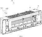
FIG. 1 is a schematic structural view of an indoor unit of a wall-mounted air conditioner according to an embodiment of the present application; -
FIG. 2 is a schematic view showing an internal structure of the indoor unit of the wall-mounted air conditioner inFIG. 1 ; -
FIG. 3 is a partial enlarged view of a portion A inFIG. 2 ; -
FIG. 4 is a schematic view showing an assembly structure of a screen assembly and a cleaning assembly inFIG. 2 ; -
FIG. 5 is a partial enlarged view of a portion B inFIG. 4 ; -
FIG. 6 is a schematic structural view of the cleaning assembly inFIG. 4 ; -
FIG. 7 is a schematic structural view of the screen assembly inFIG. 4 ; -
FIG. 8 is a partial enlarged view of a portion C inFIG. 7 ; -
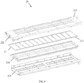
FIG. 9 is a schematic exploded structural view of the screen assembly inFIG. 7 ; -
FIG. 10 is a schematic structural view of a chassis inFIG. 2 ; and -
FIG. 11 is a partial enlarged view of a portion D inFIG. 10 . -
Reference numeral Name Reference numeral Name 100 Indoor unit 223 First threaded hole 10 Chassis 225 Bottom bracket 11 Bottom wall 226 Screen bracket 111 Accommodating space 227 Air- inlet grille 12 Rear side wall 30 Cleaning assembly 121 Threaded hole column 31 Cleaning box 122 Second threaded hole 311 First buckle 123 Third buckle hole 312 Second buckle 20 Screen assembly 313 Third connecting member 21 Screen 3131 First via hole 211 Engaging member 314 Fourth connecting member 22 Grille assembly 3141 Second via hole 221 First connecting member 32 Roller brush assembly 2211 First buckle hole 321 Roller brush 222 Second connecting member 322 Gear 2221 Second buckle hole 40 Face frame - The implementation, functional features and advantages of the present application will be further described with reference to the accompanying drawings.
- The technical solutions in the embodiments of the present application are clearly and completely described in the following with reference to the drawings in the embodiments of the present application. It is obvious that the described embodiments are only a part of the embodiments of the present application, and not all of the embodiments. All other embodiments obtained by a person having ordinary skill in the art based on the embodiments of the present application without making any creative work fall within the scope of the present application.
- It should be noted that, if there is a directional indicator (such as up, down, left, right, front, rear, ...) in the embodiment of the present application, it is only used to explain the relative position relationship and movement of the components in a particular posture (as shown in the attached drawings), and if the specific posture changes, the directional indicator will change accordingly.
- In addition, if there is a description relating to "first", "second", etc. in the embodiments of the present disclosure, it is used for descriptive purposes only, and cannot be understood to indicate or imply its relative importance or to imply the number of technical features indicated. Thus, features defining "first" or "second" may include at least one of the features, either explicitly or implicitly. In addition, the meaning of "and/or" appearing throughout the text includes three parallel solutions, taking "A and/or B" as an example, it includes the A solution, or the B solution, or the solution in which both A and B are simultaneously satisfied. In addition, the technical solutions between the various embodiments may be combined with each other, but must be based on the realization of those skilled in the art, and when the combination of the technical solutions is contradictory or impossible to implement, it should be considered that the combination of the technical solutions does not exist, nor is it within the scope of protection required by the present disclosure.
- The present application provides an indoor unit of a wall-mounted air conditioner.
- In some embodiments of the present application, as shown in
FIGS. 1-3 , theindoor unit 100 of the wall-mounted air conditioner includes: - a
chassis 10; - a
screen assembly 20; and - a cleaning
assembly 30 disposed at one end of thescreen assembly 20 and connected with thescreen assembly 20 by a fastening structure; - where the cleaning
assembly 30 is mounted on thechassis 10, or thescreen assembly 20 is mounted on thechassis 10, or the cleaningassembly 30 and thescreen assembly 20 are both mounted on thechassis 10. - It will be understood that the fastening structure is a structure that securely connects the cleaning
assembly 30 and thescreen assembly 20, which is configured to improve the connection stability between the cleaningassembly 30 and thescreen assembly 20. - Specifically, when the
indoor unit 100 of the wall-mounted air conditioner is assembled, the cleaningassembly 30 and thescreen assembly 20 are connected by the fastening structure, and agear 322 of the cleaningassembly 30 and ascreen 21 of thescreen assembly 20 are simultaneously engaged (where thescreen 21 is provided with an engagingmember 211 configured for engaging with the gear 322); then, the cleaningassembly 30 together with thescreen assembly 20 are mounted on thechassis 10. As such, the cleaningassembly 30 and thescreen assembly 20 are fixedly connected by the fastening structure, thereby improving the connection stability between the cleaningassembly 30 and thescreen assembly 20 and further improving the engaging stability of thegear 322 of the cleaningassembly 30 and thescreen 21 of thescreen assembly 20; so that the defects such as misalignment, jamming, abnormal noise, etc. of the engaging transmission between thegear 322 and thescreen 21 may be avoided in the process of washing, thereby improving the transmission reliability of thescreen 21 in the washing process. - Namely, according to the
indoor unit 100 of the wall-mounted air conditioner of the present application, the cleaningassembly 30 and thescreen assembly 20 are fixedly connected by the fastening structure, thereby improving the connection stability between the cleaningassembly 30 and thescreen assembly 20 and further improving the engaging stability of thegear 322 of the cleaningassembly 30 and thescreen 21; so that the defects such as misalignment, jamming, abnormal noise, etc. of the engaging transmission between thegear 322 and thescreen 21 may be avoided in the process of washing, thereby improving the transmission reliability of thescreen 21 in the washing process. - Secondly, the cleaning
assembly 30 and thescreen assembly 20 are fixedly connected by the fastening structure, so that loosening of the engagedgear 322 and thescreen 21 due to changed relative position of the cleaningassembly 30 and thescreen assembly 20 caused by shaking and/or collision during transportation may be avoided. - In addition, the assembly sequence of the
indoor unit 100 of the wall-mounted air conditioner is: the cleaningassembly 30 and thescreen assembly 20 are first fixedly connected by the fastening structure, and then the cleaningassembly 30 together with thescreen assembly 20 are mounted on thechassis 10. The above assembly sequence is very convenient for checking the connection points on the production line. - In a specific embodiment, there may be various specific structures of the fastening structure, as long as the cleaning
assembly 30 and thescreen assembly 20 may be securely connected together to stabilize the relative positions of the two. For example, the fastening structure may include one or more of a snap structure, a threaded structure, a pin connection structure, a welded connection structure, etc. The fastening structure will be exemplified below, and it will be understood that many fastening structures are readily apparent to those skilled in the art on the basis of the following examples. - Further, the fastening structure is a detachable structure. As such, inspection, repair, replacement, etc. of the cleaning
assembly 30 and/or thescreen assembly 20 may be facilitated. - In some embodiment, as shown in
FIGS. 6-9 , thescreen assembly 20 includes ascreen 21 and agrille assembly 22. The cleaningassembly 30 includes acleaning box 31 and aroll brush assembly 32 mounted on thecleaning box 31, and thegear 322 is a part of theroller brush assembly 32. Thescreen 21 is provided with an engagingmember 211 for engaging with thegear 322. Specifically, the fastening structure connects thecleaning box 31 and thegrille assembly 22. - In some embodiments, as shown in
FIG. 7 , thegrille assembly 22 is substantially rectangular. - Further, as shown in
FIGS. 4 and5 , the fastening structure includes a first buckle structure and a first threaded structure. As such, the combination of the buckle structure and the threaded structure to secure the cleaningassembly 30 and thescreen assembly 20 not only facilitates positioning during assembly, but also improves the stability of the connection between the cleaningassembly 30 and thescreen assembly 20. In addition, it is also advantageous to simplify the structure of the fastening structure. - Certainly, the fastening structure may also include a first buckle structure only or a first threaded structure only.
- Further, as shown in
FIGS. 4 and5 , thecleaning box 31 is disposed below thegrille assembly 22, and a first connectingmember 221 extends downwardly from one end of thegrille assembly 22. - The first buckle structure includes a
first buckle hole 2211 defined in the first connectingmember 221 and afirst buckle 311 protruded from thecleaning box 31. Thefirst buckle 311 is adaptively engaged in thefirst buckle hole 2211. Optionally, thefirst buckle 311 is disposed in an outer side of thecleaning box 31. - Specifically, as shown in
FIG. 6 , thecleaning box 31 is substantially rectangular. InFIGS. 2 and3 , thefirst buckle 311 is disposed in a left side of thecleaning box 31. - As such, the end of the
grille assembly 22 may be constrained and connected to the left lateral side of thecleaning box 31. - It can be understood that the
first buckle 311 may also be disposed in the first connectingmember 221, and correspondingly, thefirst buckle hole 2211 may be defined in thecleaning box 31. Namely, the first buckle structure includes thefirst buckle hole 2211 defined in thecleaning box 31, and thefirst buckle 311 protruded from the first connectingmember 221, where thefirst buckle 311 is adaptively engaged in thefirst buckle hole 2211. - Specifically, as shown in
FIGS. 7 and8 , the first connectingmember 221 may be provided in a plate shape. As such, the structure and manufacturing process of the first connectingmember 221 may be simplified. - Specifically, a side surface of the
first buckle 311 toward thefirst buckle hole 2211 is obliquely extended to guide the engagement between the first connectingmember 221 and thecleaning box 31. - Further, as shown in
FIG. 2 ,FIG. 7 andFIG. 8 , two of the first connectingmembers 221 are provided at intervals along a front-rear direction, and each first connectingmember 221 defines thefirst buckle hole 2211 respectively, and two of thefirst buckles 311 are provided accordingly. As such, the connection strength and the connection stability may be improved. - Further, as shown in
FIGS. 4-8 , a second connectingmember 222 extends downwardly from a front portion of thegrille assembly 22. The first buckle structure further includes asecond buckle hole 2221 defined in the second connectingmember 222 and asecond buckle 312 protruded from thecleaning box 31. Thesecond buckle 312 is adaptively engaged in thesecond buckle hole 2221. Optionally, thesecond buckle 312 is disposed in an outer side of thecleaning box 31. - Specifically, in
FIGS. 2 and3 , thesecond buckle 312 is disposed in a front side of thecleaning box 31. - As such, the front portion of the
grille assembly 22 may be constrained and connected with the front lateral side of thecleaning box 31. - It can be understood that the
second buckle 312 may also be disposed in the second connectingmember 222, and correspondingly, thesecond buckle hole 2221 is defined in thecleaning box 31. Namely, the first buckle structure further includes thesecond buckle hole 2221 defined in thecleaning box 31, and thesecond buckle 312 protruded from the second connectingmember 222, where thesecond buckle 312 is adaptively engaged in thesecond buckle hole 2221. - Specifically, as shown in
FIGS. 7 and8 , the second connectingmember 222 may be provided in a plate shape. As such, the structure and manufacturing process of the second connectingmember 222 may be simplified. - Specifically, a side surface of the
second buckle 311 toward thesecond buckle hole 2211 is obliquely extended to further guide the engagement between the first connectingmember 221 and thecleaning box 31. - Further, as shown in
FIGS. 7 and8 , two of the second connectingmembers 222 are provided at intervals along a length direction of the screen assembly 20 (namely the left-right direction inFIG. 2 ), and each second connectingmember 222 defines asecond buckle hole 2221 respectively, and two of thesecond buckle 312 are provided accordingly. As such, the connection strength and the connection stability may be improved. - It can be understood that the first connecting
member 221 extends downwardly from the end of thegrille assembly 22, and thefirst buckle hole 2211 is defined in the first connectingmember 221 to be engaged with thefirst buckle 311 disposed in thecleaning box 31, so that the end of thegrille assembly 22 and the left lateral side of the cleaning box may be constrained and connected. Further, the second connectingmember 222 extends downwardly from the front portion of thegrille assembly 22, and thesecond buckle hole 2221 is defined in the second connecting member to be engaged with thesecond buckle 312 disposed in the cleaning box, so that the front portion of thegrille assembly 11 and the front lateral side of thecleaning box 31 may be constrained and connected. As such, thecleaning box 31 and thegrille assembly 22 may be fastened. - It should be noted that, the first buckle structure may also be set in other structural forms according to the first buckle structure mentioned above, which will not be detailed here.
- Further, as shown in
FIGS. 4-6 , a third connectingmember 313 extends upwardly from an edge of an opening of thecleaning box 31, where the first threaded structure includes a first locking screw (not shown), and the first locking screw penetrates the third connectingmember 313 and is threaded with one end of thegrille assembly 22, so as to connect thecleaning box 31 and thegrille assembly 22. - Specifically, as shown in
FIGS. 4-6 , the first threaded structure further includes a first viahole 3131 defined in the third connectingmember 313, and a first threadedhole 223 defined in an end surface of thegrille assembly 22, where the first locking screw penetrates the first viahole 3131 and is threaded to the first threadedhole 223. - It can be understood that an end surface where the first threaded
hole 223 located is an end surface of an end where the first connectingmember 221 located, and the third connectingmember 313 is disposed on a left lateral side of thecleaning box 31. - As such, the strength of the connection between the
cleaning box 31 and thegrille assembly 22 may be further enhanced to further improve the stability of the connection between the cleaningassembly 30 and thescreen assembly 20. - Specifically, as shown in
FIGS. 2 and3 , the third connectingmember 313 is disposed on a rear side of the edge of the opening of thecleaning box 31, and the first threadedhole 223 is defined in a rear side of the end face. - Further, the first via
hole 3131 may be a threaded hole. As such, the connection ability of the first threaded structure may be improved, so as to improve the connection stability between thecleaning box 31 and thegrille assembly 22. - It can be understood that the first locking screw may also be replaced by a bolt or the like.
- It should be noted that, the first threaded structure may also be set in other structural forms according to the first threaded structure mentioned above, which will not be detailed here.
- Further, as shown in
FIG. 10 , thechassis 10 includes abottom wall 11 and arear side wall 12 connected to a rear side of thebottom wall 11. - Specifically, the
bottom wall 11 and therear side wall 12 may be integrally formed. - As shown in
FIG. 10 , thebottom wall 11 defines anaccommodating space 111, and a lower portion of the cleaningassembly 30 is mounted in theaccommodating space 111. - Specifically, a lower portion of the
cleaning box 31 is mounted in theaccommodating space 111. - As such, a lower portion of the cleaning
assembly 30 may be restrained to ensure mounting stability between the cleaningassembly 30 and thescreen assembly 20 on thechassis 10. - Specifically, as shown in
FIG. 10 , two limit plates (not labeled) are provided at intervals on thebottom wall 11 in the length direction of the chassis 10 (namely the left-right direction inFIG. 10 ), and the two limit plates and therear side walls 12 are enclosed to define theaccommodating space 111 cooperatively. As such, the structure of theaccommodating space 111 may be simplified. - Certainly, the
accommodating space 111 may also be set to other structural forms. - Further, as shown in
FIGS. 2 ,3 , and10 , an upper portion of the cleaningassembly 30 is connected with therear side wall 12 by a second threaded structure, and/or thescreen assembly 20 is connected with therear side wall 12 by a second buckle structure. - Specifically, an upper portion of the
cleaning box 31 is connected with therear side wall 12 by a second threaded structure, and/or thegrille assembly 22 is connected with therear side wall 12 by a second buckle structure. - As such, an upper portion of the cleaning
assembly 30 may be restrained to further ensure mounting stability between the cleaningassembly 30 and thescreen assembly 20 on thechassis 10. - In some embodiments of the present application, as shown in
FIGS. 2 ,3 , and10 , an upper portion of the cleaningassembly 30 is connected with therear side wall 12 by a second threaded structure, and thescreen assembly 20 is connected with therear side wall 12 by a second buckle structure. As such, not only the mounting stability between the cleaningassembly 30 and thescreen assembly 20 on thechassis 10 may be further improved and shaking during transportation may be avoided; but also the installation difficulty may be reduced during installation, since the upper portion of the cleaningassembly 30 may be firstly fixed through the second buckle structure and then the second threaded structure is installed. - Further, as shown in
FIGS. 2 ,3 , and10 , a fourth connectingmember 314 is protruded from thecleaning box 31 and extended away from the other end of thescreen assembly 20. The second threaded structure includes a second locking screw (not shown), and the second locking screw penetrates the fourth connectingmember 314 and is threaded with therear side wall 12. Optionally, the fourth connectingmember 314 is disposed on an outer lateral side of thecleaning box 31. - Specifically, the second threaded structure further includes a second via
hole 3141 defined in the fourth connectingmember 314 and a second threadedhole 122 defined in therear side wall 12. The second locking screw penetrates the second viahole 3141 and is threaded into the second threadedhole 122. - As such, the upper portion of the
cleaning box 31 may be mounted on thechassis 10. - Specifically, in
FIGS. 3 and4 , the fourth connectingmember 314 is disposed on the left lateral side of thecleaning box 31. - Specifically, as shown in
FIG. 10 andFIG. 11 , a threadedhole column 121 may be protruded from therear side wall 12, and the second threadedhole 122 may be defined in the threaded hole column121. - Further, the second via
hole 3141 may be a threaded hole. As such, the connection ability of the second threaded structure may be improved, so as to improve the connection stability between thecleaning box 31 and thechassis 10. - It can be understood that the second locking screw may also be replaced by a bolt or the like.
- Further, as shown in
FIG. 2 ,FIG. 3 andFIG. 10 , the second buckle structure includes athird buckle hole 123 defined in therear side wall 12 and an inserting buckle protruded from the screen assembly 20 (not shown), and the inserting buckle is inserted into thethird fastening buckle 123. Optionally, the inserting buckle is disposed on an outer side of thescreen assembly 20. - Specifically, the inserting buckle may be disposed on an outer side of the
grille assembly 22. - As such, the
screen assembly 20 may be mounted on thechassis 10 to improve mounting stability between the cleaningassembly 30 and thescreen assembly 20 on thechassis 10. - In some embodiments, the inserting buckle may be disposed on a rear side of the
grille assembly 22. - It can be understood that the inserting buckle may also be disposed on the
rear side wall 12, and correspondingly, thethird buckle hole 123 may be defined in thescreen assembly 20. Namely, the second buckle structure includes thethird buckle hole 123 defined in thescreen assembly 20 and the inserting buckle protruded from therear side wall 12, and the inserting buckle is inserted into thethird buckle hole 123. - Further, a plurality of the third buckle holes 123 are provided at intervals in the length direction of the chassis 10 (namely the left-right direction in
FIG. 10 ), and a plurality of inserting buckles are correspondingly provided. As such, the mounting stability between thescreen assembly 20 and thechassis 10 may be improved. - Further, as shown in
FIGS. 2 ,3 ,6 , and10 , the fourth connectingmember 314 may be integrally formed on a rear side edge of the third connectingmember 313. As such, the structure of thecleaning box 31 may be simplified. - Further, the engaging
member 211 may be a rack. Thus, the engaging between the engagingmember 211 and thegear 322 may be achieved. - Specifically, two of the racks may be provided and disposed on both sides of the
screen 21 respectively. - Certainly, the engaging
member 211 may also be set to other structural forms. For example, the engagingmember 211 defines at least one engaging hole for engaging with thegear 322. - Further, as shown in
FIG. 1 , theindoor unit 100 of the wall-mounted air conditioner further includes aface frame 40 detachably mounted on thechassis 10, where theface frame 40 and thechassis 10 defines an accommodating cavity (not labeled) cooperatively, and thescreen assembly 20 and the cleaningassembly 30 are mounted in the accommodating cavity. - Specifically, when the
indoor unit 100 of the wall-mounted air conditioner is assembled, theface frame 40 is mounted after the cleaningassembly 30 and thescreen assembly 20 are mounted on thechassis 10. - Specifically, the
face frame 40 defines an air outlet corresponding to thescreen assembly 20. - Specifically, as shown in
FIG. 6 , theroller brush assembly 32 generally includes aroller brush 321 rotatably mounted at the opening of thecleaning box 31, and twogears 322 mounted on both ends of theroller brush 321. Theroller brush 321 is used to clean thescreen 21. Thegear 322 is used to engage with thescreen 21 to drive thescreen 21 to move. - In some embodiments, the
roller brush 321 includes a roller (not labeled) rotatably mounted on thecleaning box 31, and a brush (not labeled) wound on the roller, where thegear 322 is mounted on roller. - In some embodiments, the cleaning
assembly 30 further includes a water-washing power assembly mounted on thecleaning box 31 for driving the roller to rotate. - The specific structure of the water-washing power assembly may be referred to related documents, and will not be repeated here.
- Further, the
grille assembly 22 defines two accommodating sliding slots (not shown) at intervals in the up-down direction. Thescreen 21 is slidably mounted in one of the accommodating sliding slots. The opening of the accommodating sliding slot is disposed adjacent to theroller brush assembly 32, and one end of thescreen 21 protrudes from the opening to engage the engagingmember 211 of thescreen 21 with thegear 322. - When the
screen 21 is needed to be washed, thegear 322 on the roller may be driven to rotate, so as to drive thegear 322 to drive thescreen 21 to slide in the accommodating sliding slot. And one end of thescreen 21 bypasses theroller 321 to enter the other accommodating sliding slot, thescreen 21 is cleaned by theroller brush 321 during the process. - Further, as shown in
FIG. 9 , thegrille assembly 22 includes abottom bracket 225, ascreen bracket 226, and anair inlet grille 227 which are sequentially stacked, and thescreen bracket 226 is disposed between thebottom bracket 225 and theair inlet grille 227. One of the accommodating sliding slot is defined between theair inlet grille 227 and thescreen 21 bracket, and the other accommodating sliding slot is defined between thebottom bracket 225 and thescreen bracket 226. - Specifically, as shown in
FIGS. 7-9 , the first connectingmember 221 and the second connectingmember 222 are both disposed on theair inlet grille 227. - Other structures of the
indoor unit 100 of the wall-mounted air conditioner may be referred to the related designs, and will not be described herein. - The above description refers to only optional embodiments of the present disclosure, and thus does not limit the scope of the present disclosure, and any transformation of equivalent structure made under the inventive concept of the present disclosure by using the contents of this specification and attached drawings, or direct/indirect application in other relevant technical fields, shall be included in the scope of the present disclosure.
Claims (20)
- An indoor unit of a wall-mounted air conditioner, characterized by comprising:a chassis;a screen assembly; anda cleaning assembly disposed at one end of the screen assembly and connected with the screen assembly by a fastening structure;wherein the cleaning assembly is mounted on the chassis, or the screen assembly is mounted on the chassis, or the cleaning assembly and the screen assembly are both mounted on the chassis.
- The indoor unit of the wall-mounted air conditioner according to claim 1, characterized in that,
the fastening structure is a detachable structure. - The indoor unit of the wall-mounted air conditioner according to claim 2, characterized in that,
the fastening structure comprises:
a first buckle structure;
or the fastening structure comprises:
a first threaded structure;
or the fastening structure comprises:a first buckle structure; anda first threaded structure. - The indoor unit of the wall-mounted air conditioner according to claim 3, characterized in that,
the screen assembly comprises:
a grille assembly comprising a first connecting member extending downwardly from one end of the grille assembly, and
wherein the cleaning assembly comprises:
a cleaning box disposed below the grille assembly;
wherein the first buckle structure comprises:a first buckle hole defined in the first connecting member; anda first buckle protruded from the cleaning box;or the first buckle structure comprises:a first buckle protruded from the first connecting member; anda first buckle hole defined in the cleaning box;wherein the first buckle is adaptively engaged in the first buckle hole. - The indoor unit of the wall-mounted air conditioner according to claim 4, characterized in that,
the first connecting member is provided in a plate shape. - The indoor unit of the wall-mounted air conditioner according to claim 4, characterized in that,
a side surface of the first buckle toward the first buckle hole is obliquely extended. - The indoor unit of the wall-mounted air conditioner according to claim 4, characterized in that,
two of the first connecting members are provided at intervals along a front-rear direction, and each first connecting member defines the first buckle hole respectively. - The indoor unit of the wall-mounted air conditioner according to claim 4, characterized in that,
the grille assembly comprises:
a second connecting member extending downwardly from a front portion of the grille assembly;
wherein the first buckle structure further comprises:a second buckle hole defined in the second connecting member; anda second buckle protruded from the cleaning box;or the first buckle structure further comprises:a second buckle protruded from the second connecting member; anda second buckle hole defined in the cleaning box;wherein the second buckle is adaptively engaged in the second buckle hole. - The indoor unit of the wall-mounted air conditioner according to claim 8, characterized in that,
the second connecting member is provided in a plate shape. - The indoor unit of the wall-mounted air conditioner according to claim 8, characterized in that,
a side surface of the second buckle toward the second buckle hole is obliquely extended. - The indoor unit of the wall-mounted air conditioner according to claim 8, characterized in that,
two of the second connecting members are provided at intervals along a length direction of the screen assembly, and each second connecting member defines the second buckle hole respectively. - The indoor unit of the wall-mounted air conditioner according to claim 3, characterized in that,
the screen assembly comprises:
a grille assembly, and
wherein the cleaning assembly comprises:
a cleaning box disposed below the grille assembly and comprising a third connecting member extending upwardly from anedge of an opening of the cleaning box, and
wherein the first threaded structure comprises:
a first locking screw penetrating the third connecting member and threaded with one end of the grille assembly. - The indoor unit of the wall-mounted air conditioner according to claim 12, characterized in that,
the third connecting member is disposed at a rear side of the opening of the cleaning box. - The indoor unit of the wall-mounted air conditioner according to claim 1, characterized in that,
the chassis comprises:a bottom wall defining an accommodating space; anda rear side wall connected to a rear side of the bottom wall,wherein a lower portion of the cleaning assembly is mounted in the accommodating space; and
wherein an upper portion of the cleaning assembly is connected with the rear side wall by a second threaded structure; or
the screen assembly is connected with the rear side wall by a second buckle structure; or
an upper portion of the cleaning assembly is connected with the rear side wall by a second threaded structure, and the screen assembly is connected with the rear side wall by a second buckle structure. - The indoor unit of the wall-mounted air conditioner according to claim 14, characterized in that,
the cleaning assembly comprises:
a fourth connecting member protruded from the cleaning box, and extended away from the other end of the screen assembly; and wherein the second threaded structure comprises:
a second locking screw penetrating the fourth connecting member and threaded with the rear side wall; and/or
wherein the second buckle structure comprises:a third buckle hole defined in the rear side wall; andan inserting buckle protruded from the screen assembly; orthe second buckle structure comprises:an inserting buckle protruded from the rear side wall; anda third buckle hole defined in the screen assembly;wherein the inserting buckle is inserted into the third buckle hole. - The indoor unit of the wall-mounted air conditioner according to claim 15, characterized in that,
the second threaded structure further comprises:a second via hole defined in the fourth connecting member; anda second threaded hole defined in the rear side wall,wherein the second locking screw is penetrated the second via hole and is threaded into the second threaded hole; and
wherein a threaded hole column is protruded from the rear side wall, and the second threaded hole is defined in the threaded hole column. - The indoor unit of the wall-mounted air conditioner according to claim 15, characterized in that,
the fourth connecting member is integrally formed on a rear side edge of the third connecting member. - The indoor unit of the wall-mounted air conditioner according to claim 15, characterized in that,
the bottom wall and the rear side wall are integrally formed. - The indoor unit of the wall-mounted air conditioner according to claim 1, characterized in that,
a gear of the cleaning assembly is engaged with an engaging member of a screen of the screen assembly,
wherein the engaging member is a rack;
or the engaging member defines at least one engaging hole. - The indoor unit of the wall-mounted air conditioner according to claim 1, characterized by further comprising:
a face frame detachably mounted on the chassis,
wherein the face frame and the chassis defines an accommodating cavity cooperatively, and the screen assembly and the cleaning assembly are mounted in the accommodating cavity.
Applications Claiming Priority (2)
| Application Number | Priority Date | Filing Date | Title |
|---|---|---|---|
| CN201920179040.5U CN209819720U (en) | 2019-01-31 | 2019-01-31 | Wall-mounted air conditioner indoor unit |
| PCT/CN2019/112431 WO2020155676A1 (en) | 2019-01-31 | 2019-10-22 | Wall-mounted indoor air conditioner unit |
Publications (3)
| Publication Number | Publication Date |
|---|---|
| EP3712516A1 true EP3712516A1 (en) | 2020-09-23 |
| EP3712516A4 EP3712516A4 (en) | 2021-02-24 |
| EP3712516B1 EP3712516B1 (en) | 2025-05-21 |
Family
ID=68872726
Family Applications (1)
| Application Number | Title | Priority Date | Filing Date |
|---|---|---|---|
| EP19798515.3A Active EP3712516B1 (en) | 2019-01-31 | 2019-10-22 | Wall-mounted indoor air conditioner unit |
Country Status (4)
| Country | Link |
|---|---|
| EP (1) | EP3712516B1 (en) |
| JP (1) | JP7139352B2 (en) |
| CN (1) | CN209819720U (en) |
| WO (1) | WO2020155676A1 (en) |
Family Cites Families (14)
| Publication number | Priority date | Publication date | Assignee | Title |
|---|---|---|---|---|
| JP5189381B2 (en) * | 2008-02-28 | 2013-04-24 | パナソニック株式会社 | Air conditioner |
| JP5040866B2 (en) * | 2008-09-09 | 2012-10-03 | ダイキン工業株式会社 | air conditioner |
| JP5800496B2 (en) * | 2010-12-06 | 2015-10-28 | 三菱電機株式会社 | Air conditioner indoor unit |
| JP6141807B2 (en) * | 2014-08-11 | 2017-06-07 | オムロンオートモーティブエレクトロニクス株式会社 | Housing for vehicle mounting |
| CN204880362U (en) * | 2015-07-06 | 2015-12-16 | 江苏春兰制冷设备股份有限公司 | Wall air conditioner's indoor set with disinfect, disinfection and air -purifying |
| CN205279257U (en) * | 2015-11-30 | 2016-06-01 | 美的集团武汉制冷设备有限公司 | Dust removal module and wall -hanging type air conditioner |
| CN105352043B (en) * | 2015-11-30 | 2018-03-27 | 美的集团武汉制冷设备有限公司 | Hanging air conditioner |
| CN205425160U (en) * | 2015-11-30 | 2016-08-03 | 美的集团武汉制冷设备有限公司 | Wall -mounting type air conditioner |
| JP2017129309A (en) * | 2016-01-20 | 2017-07-27 | 三菱重工業株式会社 | Air conditioner |
| CN206959170U (en) * | 2017-07-21 | 2018-02-02 | 广东美的制冷设备有限公司 | Indoor apparatus of air conditioner and there is its air conditioner |
| JP2018200170A (en) * | 2018-09-20 | 2018-12-20 | シャープ株式会社 | Air cleaning mechanism |
| CN109185987A (en) * | 2018-09-30 | 2019-01-11 | 广东美的制冷设备有限公司 | Washing module and air conditioner room unit |
| CN208936323U (en) * | 2018-09-30 | 2019-06-04 | 广东美的制冷设备有限公司 | Washing module and air conditioner room unit |
| CN209672479U (en) * | 2019-03-03 | 2019-11-22 | 广东美的制冷设备有限公司 | Wall-hanging air conditioner indoor unit and cleaning device |
-
2019
- 2019-01-31 CN CN201920179040.5U patent/CN209819720U/en active Active
- 2019-10-22 EP EP19798515.3A patent/EP3712516B1/en active Active
- 2019-10-22 JP JP2019563126A patent/JP7139352B2/en active Active
- 2019-10-22 WO PCT/CN2019/112431 patent/WO2020155676A1/en not_active Ceased
Also Published As
| Publication number | Publication date |
|---|---|
| EP3712516B1 (en) | 2025-05-21 |
| JP2021515163A (en) | 2021-06-17 |
| JP7139352B2 (en) | 2022-09-20 |
| WO2020155676A1 (en) | 2020-08-06 |
| CN209819720U (en) | 2019-12-20 |
| EP3712516A4 (en) | 2021-02-24 |
Similar Documents
| Publication | Publication Date | Title |
|---|---|---|
| US5992955A (en) | Structure of computer | |
| JP2006162094A (en) | Air conditioner outdoor unit | |
| CN210463461U (en) | Electric Control Box Components and Window Air Conditioners | |
| EP3712516A1 (en) | Wall-mounted indoor air conditioner unit | |
| CN205878512U (en) | Grid assembly and interior machine of air conditioning of machine in air conditioning | |
| CN214791547U (en) | A shell support column, an air conditioner shell and an air conditioner | |
| CN217685376U (en) | Air conditioner | |
| CN213817395U (en) | Motor installation component and fresh air fan with same | |
| EP3726161B1 (en) | Face frame assembly, air conditioner indoor unit, and air conditioner | |
| CN211767060U (en) | Assembly storage rack | |
| CN210463291U (en) | Air pipe type air conditioner | |
| CN109764524B (en) | Guide rail structure, face frame assembly, face frame, air conditioner indoor unit and air conditioner | |
| CN222210705U (en) | Shell part and air conditioner with same | |
| CN223782941U (en) | air conditioner | |
| CN222783707U (en) | Panel assembly, casing assembly and air conditioner | |
| CN217428619U (en) | Shielding case and electronic equipment | |
| CN219419992U (en) | Outer knot hangs shrouding structure and shield case becomes | |
| CN212870190U (en) | Base structure of cabinet type ventilator and cabinet type ventilator | |
| CN222310754U (en) | Profile type carriage and vehicle | |
| CN223050186U (en) | Air conditioner and its box reinforcement structure | |
| CN221424960U (en) | Indoor unit and air conditioner | |
| CN221122699U (en) | Connecting assembly and embedded refrigerator door body assembly | |
| CN220439801U (en) | Support structure and battery pack | |
| CN219243847U (en) | Display box for air conditioner and air conditioner with same | |
| CN216307977U (en) | Air conditioner indoor unit and air conditioner |
Legal Events
| Date | Code | Title | Description |
|---|---|---|---|
| STAA | Information on the status of an ep patent application or granted ep patent |
Free format text: STATUS: UNKNOWN |
|
| STAA | Information on the status of an ep patent application or granted ep patent |
Free format text: STATUS: THE INTERNATIONAL PUBLICATION HAS BEEN MADE |
|
| PUAI | Public reference made under article 153(3) epc to a published international application that has entered the european phase |
Free format text: ORIGINAL CODE: 0009012 |
|
| STAA | Information on the status of an ep patent application or granted ep patent |
Free format text: STATUS: REQUEST FOR EXAMINATION WAS MADE |
|
| 17P | Request for examination filed |
Effective date: 20191115 |
|
| AK | Designated contracting states |
Kind code of ref document: A1 Designated state(s): AL AT BE BG CH CY CZ DE DK EE ES FI FR GB GR HR HU IE IS IT LI LT LU LV MC MK MT NL NO PL PT RO RS SE SI SK SM TR |
|
| AX | Request for extension of the european patent |
Extension state: BA ME |
|
| A4 | Supplementary search report drawn up and despatched |
Effective date: 20210121 |
|
| RIC1 | Information provided on ipc code assigned before grant |
Ipc: F24F 1/0073 20190101AFI20210115BHEP Ipc: F24F 13/28 20060101ALI20210115BHEP Ipc: F24F 1/0057 20190101ALI20210115BHEP |
|
| RAP3 | Party data changed (applicant data changed or rights of an application transferred) |
Owner name: MIDEA GROUP CO., LTD. Owner name: GD MIDEA AIR-CONDITIONING EQUIPMENT CO., LTD. |
|
| DAV | Request for validation of the european patent (deleted) | ||
| DAX | Request for extension of the european patent (deleted) | ||
| STAA | Information on the status of an ep patent application or granted ep patent |
Free format text: STATUS: EXAMINATION IS IN PROGRESS |
|
| 17Q | First examination report despatched |
Effective date: 20230310 |
|
| GRAP | Despatch of communication of intention to grant a patent |
Free format text: ORIGINAL CODE: EPIDOSNIGR1 |
|
| STAA | Information on the status of an ep patent application or granted ep patent |
Free format text: STATUS: GRANT OF PATENT IS INTENDED |
|
| INTG | Intention to grant announced |
Effective date: 20250227 |
|
| GRAS | Grant fee paid |
Free format text: ORIGINAL CODE: EPIDOSNIGR3 |
|
| GRAA | (expected) grant |
Free format text: ORIGINAL CODE: 0009210 |
|
| STAA | Information on the status of an ep patent application or granted ep patent |
Free format text: STATUS: THE PATENT HAS BEEN GRANTED |
|
| AK | Designated contracting states |
Kind code of ref document: B1 Designated state(s): AL AT BE BG CH CY CZ DE DK EE ES FI FR GB GR HR HU IE IS IT LI LT LU LV MC MK MT NL NO PL PT RO RS SE SI SK SM TR |
|
| REG | Reference to a national code |
Ref country code: GB Ref legal event code: FG4D |
|
| REG | Reference to a national code |
Ref country code: CH Ref legal event code: EP |
|
| REG | Reference to a national code |
Ref country code: DE Ref legal event code: R096 Ref document number: 602019070290 Country of ref document: DE |
|
| REG | Reference to a national code |
Ref country code: IE Ref legal event code: FG4D |
|
| REG | Reference to a national code |
Ref country code: NL Ref legal event code: MP Effective date: 20250521 |
|
| PG25 | Lapsed in a contracting state [announced via postgrant information from national office to epo] |
Ref country code: PT Free format text: LAPSE BECAUSE OF FAILURE TO SUBMIT A TRANSLATION OF THE DESCRIPTION OR TO PAY THE FEE WITHIN THE PRESCRIBED TIME-LIMIT Effective date: 20250922 Ref country code: ES Free format text: LAPSE BECAUSE OF FAILURE TO SUBMIT A TRANSLATION OF THE DESCRIPTION OR TO PAY THE FEE WITHIN THE PRESCRIBED TIME-LIMIT Effective date: 20250521 Ref country code: FI Free format text: LAPSE BECAUSE OF FAILURE TO SUBMIT A TRANSLATION OF THE DESCRIPTION OR TO PAY THE FEE WITHIN THE PRESCRIBED TIME-LIMIT Effective date: 20250521 |
|
| REG | Reference to a national code |
Ref country code: LT Ref legal event code: MG9D |
|
| PG25 | Lapsed in a contracting state [announced via postgrant information from national office to epo] |
Ref country code: NO Free format text: LAPSE BECAUSE OF FAILURE TO SUBMIT A TRANSLATION OF THE DESCRIPTION OR TO PAY THE FEE WITHIN THE PRESCRIBED TIME-LIMIT Effective date: 20250821 Ref country code: GR Free format text: LAPSE BECAUSE OF FAILURE TO SUBMIT A TRANSLATION OF THE DESCRIPTION OR TO PAY THE FEE WITHIN THE PRESCRIBED TIME-LIMIT Effective date: 20250822 |
|
| PG25 | Lapsed in a contracting state [announced via postgrant information from national office to epo] |
Ref country code: PL Free format text: LAPSE BECAUSE OF FAILURE TO SUBMIT A TRANSLATION OF THE DESCRIPTION OR TO PAY THE FEE WITHIN THE PRESCRIBED TIME-LIMIT Effective date: 20250521 Ref country code: NL Free format text: LAPSE BECAUSE OF FAILURE TO SUBMIT A TRANSLATION OF THE DESCRIPTION OR TO PAY THE FEE WITHIN THE PRESCRIBED TIME-LIMIT Effective date: 20250521 |
|
| PG25 | Lapsed in a contracting state [announced via postgrant information from national office to epo] |
Ref country code: BG Free format text: LAPSE BECAUSE OF FAILURE TO SUBMIT A TRANSLATION OF THE DESCRIPTION OR TO PAY THE FEE WITHIN THE PRESCRIBED TIME-LIMIT Effective date: 20250521 |
|
| PG25 | Lapsed in a contracting state [announced via postgrant information from national office to epo] |
Ref country code: HR Free format text: LAPSE BECAUSE OF FAILURE TO SUBMIT A TRANSLATION OF THE DESCRIPTION OR TO PAY THE FEE WITHIN THE PRESCRIBED TIME-LIMIT Effective date: 20250521 |
|
| PG25 | Lapsed in a contracting state [announced via postgrant information from national office to epo] |
Ref country code: RS Free format text: LAPSE BECAUSE OF FAILURE TO SUBMIT A TRANSLATION OF THE DESCRIPTION OR TO PAY THE FEE WITHIN THE PRESCRIBED TIME-LIMIT Effective date: 20250821 |
|
| PG25 | Lapsed in a contracting state [announced via postgrant information from national office to epo] |
Ref country code: IS Free format text: LAPSE BECAUSE OF FAILURE TO SUBMIT A TRANSLATION OF THE DESCRIPTION OR TO PAY THE FEE WITHIN THE PRESCRIBED TIME-LIMIT Effective date: 20250921 |
|
| PG25 | Lapsed in a contracting state [announced via postgrant information from national office to epo] |
Ref country code: LV Free format text: LAPSE BECAUSE OF FAILURE TO SUBMIT A TRANSLATION OF THE DESCRIPTION OR TO PAY THE FEE WITHIN THE PRESCRIBED TIME-LIMIT Effective date: 20250521 |
|
| REG | Reference to a national code |
Ref country code: AT Ref legal event code: MK05 Ref document number: 1797027 Country of ref document: AT Kind code of ref document: T Effective date: 20250521 |
|
| PGFP | Annual fee paid to national office [announced via postgrant information from national office to epo] |
Ref country code: DE Payment date: 20251027 Year of fee payment: 7 |
|
| PG25 | Lapsed in a contracting state [announced via postgrant information from national office to epo] |
Ref country code: DK Free format text: LAPSE BECAUSE OF FAILURE TO SUBMIT A TRANSLATION OF THE DESCRIPTION OR TO PAY THE FEE WITHIN THE PRESCRIBED TIME-LIMIT Effective date: 20250521 Ref country code: SM Free format text: LAPSE BECAUSE OF FAILURE TO SUBMIT A TRANSLATION OF THE DESCRIPTION OR TO PAY THE FEE WITHIN THE PRESCRIBED TIME-LIMIT Effective date: 20250521 Ref country code: AT Free format text: LAPSE BECAUSE OF FAILURE TO SUBMIT A TRANSLATION OF THE DESCRIPTION OR TO PAY THE FEE WITHIN THE PRESCRIBED TIME-LIMIT Effective date: 20250521 |
|
| PG25 | Lapsed in a contracting state [announced via postgrant information from national office to epo] |
Ref country code: CZ Free format text: LAPSE BECAUSE OF FAILURE TO SUBMIT A TRANSLATION OF THE DESCRIPTION OR TO PAY THE FEE WITHIN THE PRESCRIBED TIME-LIMIT Effective date: 20250521 |
|
| PG25 | Lapsed in a contracting state [announced via postgrant information from national office to epo] |
Ref country code: EE Free format text: LAPSE BECAUSE OF FAILURE TO SUBMIT A TRANSLATION OF THE DESCRIPTION OR TO PAY THE FEE WITHIN THE PRESCRIBED TIME-LIMIT Effective date: 20250521 |
|
| PG25 | Lapsed in a contracting state [announced via postgrant information from national office to epo] |
Ref country code: SK Free format text: LAPSE BECAUSE OF FAILURE TO SUBMIT A TRANSLATION OF THE DESCRIPTION OR TO PAY THE FEE WITHIN THE PRESCRIBED TIME-LIMIT Effective date: 20250521 Ref country code: RO Free format text: LAPSE BECAUSE OF FAILURE TO SUBMIT A TRANSLATION OF THE DESCRIPTION OR TO PAY THE FEE WITHIN THE PRESCRIBED TIME-LIMIT Effective date: 20250521 |
|
| PG25 | Lapsed in a contracting state [announced via postgrant information from national office to epo] |
Ref country code: IT Free format text: LAPSE BECAUSE OF FAILURE TO SUBMIT A TRANSLATION OF THE DESCRIPTION OR TO PAY THE FEE WITHIN THE PRESCRIBED TIME-LIMIT Effective date: 20250521 |
|
| REG | Reference to a national code |
Ref country code: DE Ref legal event code: R097 Ref document number: 602019070290 Country of ref document: DE |
|
| PLBE | No opposition filed within time limit |
Free format text: ORIGINAL CODE: 0009261 |
|
| STAA | Information on the status of an ep patent application or granted ep patent |
Free format text: STATUS: NO OPPOSITION FILED WITHIN TIME LIMIT |
|
| REG | Reference to a national code |
Ref country code: CH Ref legal event code: L10 Free format text: ST27 STATUS EVENT CODE: U-0-0-L10-L00 (AS PROVIDED BY THE NATIONAL OFFICE) Effective date: 20260402 |
|
| 26N | No opposition filed |
Effective date: 20260224 |