EP3712465A1 - Pressing device for toroidal continuously variable transmission - Google Patents
Pressing device for toroidal continuously variable transmission Download PDFInfo
- Publication number
- EP3712465A1 EP3712465A1 EP18877491.3A EP18877491A EP3712465A1 EP 3712465 A1 EP3712465 A1 EP 3712465A1 EP 18877491 A EP18877491 A EP 18877491A EP 3712465 A1 EP3712465 A1 EP 3712465A1
- Authority
- EP
- European Patent Office
- Prior art keywords
- axial direction
- oil
- cam
- circumferential
- radial direction
- Prior art date
- Legal status (The legal status is an assumption and is not a legal conclusion. Google has not performed a legal analysis and makes no representation as to the accuracy of the status listed.)
- Granted
Links
Images



Classifications
-
- F—MECHANICAL ENGINEERING; LIGHTING; HEATING; WEAPONS; BLASTING
- F16—ENGINEERING ELEMENTS AND UNITS; GENERAL MEASURES FOR PRODUCING AND MAINTAINING EFFECTIVE FUNCTIONING OF MACHINES OR INSTALLATIONS; THERMAL INSULATION IN GENERAL
- F16H—GEARING
- F16H15/00—Gearings for conveying rotary motion with variable gear ratio, or for reversing rotary motion, by friction between rotary members
- F16H15/02—Gearings for conveying rotary motion with variable gear ratio, or for reversing rotary motion, by friction between rotary members without members having orbital motion
- F16H15/04—Gearings providing a continuous range of gear ratios
- F16H15/06—Gearings providing a continuous range of gear ratios in which a member A of uniform effective diameter mounted on a shaft may co-operate with different parts of a member B
- F16H15/32—Gearings providing a continuous range of gear ratios in which a member A of uniform effective diameter mounted on a shaft may co-operate with different parts of a member B in which the member B has a curved friction surface formed as a surface of a body of revolution generated by a curve which is neither a circular arc centered on its axis of revolution nor a straight line
- F16H15/36—Gearings providing a continuous range of gear ratios in which a member A of uniform effective diameter mounted on a shaft may co-operate with different parts of a member B in which the member B has a curved friction surface formed as a surface of a body of revolution generated by a curve which is neither a circular arc centered on its axis of revolution nor a straight line with concave friction surface, e.g. a hollow toroid surface
- F16H15/38—Gearings providing a continuous range of gear ratios in which a member A of uniform effective diameter mounted on a shaft may co-operate with different parts of a member B in which the member B has a curved friction surface formed as a surface of a body of revolution generated by a curve which is neither a circular arc centered on its axis of revolution nor a straight line with concave friction surface, e.g. a hollow toroid surface with two members B having hollow toroid surfaces opposite to each other, the member or members A being adjustably mounted between the surfaces
-
- F—MECHANICAL ENGINEERING; LIGHTING; HEATING; WEAPONS; BLASTING
- F16—ENGINEERING ELEMENTS AND UNITS; GENERAL MEASURES FOR PRODUCING AND MAINTAINING EFFECTIVE FUNCTIONING OF MACHINES OR INSTALLATIONS; THERMAL INSULATION IN GENERAL
- F16H—GEARING
- F16H57/00—General details of gearing
- F16H57/04—Features relating to lubrication or cooling or heating
- F16H57/048—Type of gearings to be lubricated, cooled or heated
- F16H57/0487—Friction gearings
- F16H57/049—Friction gearings of the toroid type
-
- F—MECHANICAL ENGINEERING; LIGHTING; HEATING; WEAPONS; BLASTING
- F16—ENGINEERING ELEMENTS AND UNITS; GENERAL MEASURES FOR PRODUCING AND MAINTAINING EFFECTIVE FUNCTIONING OF MACHINES OR INSTALLATIONS; THERMAL INSULATION IN GENERAL
- F16H—GEARING
- F16H61/00—Control functions within control units of change-speed- or reversing-gearings for conveying rotary motion ; Control of exclusively fluid gearing, friction gearing, gearings with endless flexible members or other particular types of gearing
- F16H61/66—Control functions within control units of change-speed- or reversing-gearings for conveying rotary motion ; Control of exclusively fluid gearing, friction gearing, gearings with endless flexible members or other particular types of gearing specially adapted for continuously variable gearings
- F16H61/664—Friction gearings
- F16H61/6649—Friction gearings characterised by the means for controlling the torque transmitting capability of the gearing
-
- F—MECHANICAL ENGINEERING; LIGHTING; HEATING; WEAPONS; BLASTING
- F16—ENGINEERING ELEMENTS AND UNITS; GENERAL MEASURES FOR PRODUCING AND MAINTAINING EFFECTIVE FUNCTIONING OF MACHINES OR INSTALLATIONS; THERMAL INSULATION IN GENERAL
- F16H—GEARING
- F16H15/00—Gearings for conveying rotary motion with variable gear ratio, or for reversing rotary motion, by friction between rotary members
- F16H15/02—Gearings for conveying rotary motion with variable gear ratio, or for reversing rotary motion, by friction between rotary members without members having orbital motion
- F16H15/04—Gearings providing a continuous range of gear ratios
- F16H15/06—Gearings providing a continuous range of gear ratios in which a member A of uniform effective diameter mounted on a shaft may co-operate with different parts of a member B
- F16H15/32—Gearings providing a continuous range of gear ratios in which a member A of uniform effective diameter mounted on a shaft may co-operate with different parts of a member B in which the member B has a curved friction surface formed as a surface of a body of revolution generated by a curve which is neither a circular arc centered on its axis of revolution nor a straight line
- F16H15/36—Gearings providing a continuous range of gear ratios in which a member A of uniform effective diameter mounted on a shaft may co-operate with different parts of a member B in which the member B has a curved friction surface formed as a surface of a body of revolution generated by a curve which is neither a circular arc centered on its axis of revolution nor a straight line with concave friction surface, e.g. a hollow toroid surface
- F16H15/38—Gearings providing a continuous range of gear ratios in which a member A of uniform effective diameter mounted on a shaft may co-operate with different parts of a member B in which the member B has a curved friction surface formed as a surface of a body of revolution generated by a curve which is neither a circular arc centered on its axis of revolution nor a straight line with concave friction surface, e.g. a hollow toroid surface with two members B having hollow toroid surfaces opposite to each other, the member or members A being adjustably mounted between the surfaces
- F16H2015/383—Gearings providing a continuous range of gear ratios in which a member A of uniform effective diameter mounted on a shaft may co-operate with different parts of a member B in which the member B has a curved friction surface formed as a surface of a body of revolution generated by a curve which is neither a circular arc centered on its axis of revolution nor a straight line with concave friction surface, e.g. a hollow toroid surface with two members B having hollow toroid surfaces opposite to each other, the member or members A being adjustably mounted between the surfaces with two or more sets of toroid gearings arranged in parallel
Definitions
- the roller rides up on convex portions of the first cam surface and the second cam surface, causing the space in the axial direction between the first cam surface and the second cam surface to increase. Accordingly, one disk on which the first cam surface is formed is pressed toward another disk that is opposed to the one disk, and the surface pressure of the traction portion is secured.
- an object of the present invention is to achieve a structure capable of preventing a thin portion having a small thickness from being formed in a cam plate even when an oil supply passage is provided in the cam plate.
- the toroidal continuously variable transmission of the present invention includes a disk, a cam plate, and a plurality of rolling bodies.
Landscapes
- Engineering & Computer Science (AREA)
- General Engineering & Computer Science (AREA)
- Mechanical Engineering (AREA)
- Friction Gearing (AREA)
- General Details Of Gearings (AREA)
Abstract
Description
- The present invention relates to a pressing device incorporated and used in a toroidal continuously variable transmission that is used, for example, as a generator for an aircraft or the like, an automatic transmission for various kinds of industrial machines such as a pump, or the like.
- The toroidal continuously variable transmission has a plurality of power rollers sandwiched between an input disk and an output disk that are arranged coaxially and able to rotate relative to each other. In such a toroidal continuously variable transmission, power is transmitted from the input disk to the output disk via the power rollers. In addition, by changing the angle of inclination of the power rollers, the gear ratio between the input disk and the output disk may be adjusted. During operation of the toroidal continuously variable transmission, an oil film of traction oil is formed on a traction portion that is a rolling contact portion between the side surface in the axial direction of the input disk and the output disk and the circumferential surface of the power roller. Power that is inputted to the input disk from a drive source such as an engine or the like is transmitted to the output disk via the oil film. In a toroidal continuously variable transmission, in order to surely transmit power through such an oil film, or in other words, in order to prevent occurrence of excessive slipping called gross slipping in the traction portion, a pressing device presses the input disk and the output disk in directions approaching each other.
- A loading cam type pressing device that mechanically generates a pressing force proportional to the magnitude of a transmission torque is described in Japanese Utility Model Laid-Open Publication No.
S62-071465 - When the loading cam type pressing device is operated, the roller rides up on convex portions of the first cam surface and the second cam surface, causing the space in the axial direction between the first cam surface and the second cam surface to increase. Accordingly, one disk on which the first cam surface is formed is pressed toward another disk that is opposed to the one disk, and the surface pressure of the traction portion is secured.
- Patent Literature 1: Japanese Utility Model Laid-Open Publication No.
S62-071465 - When a loading cam type pressing device is operated, or in other words, when a pressing force is generated, the rolling surface of a roller is held between a first cam surface and a second cam surface with a strong force. Moreover, while a toroidal continuously variable transmission is operated at a constant gear ratio, the amount by which the roller rides up on convex portions of the first cam surface and the second cam surface is constant, and the roller does not roll. Therefore, when a slight slippage occurs between the rolling surface of the roller and the first cam surface and the second cam surface, there is a possibility that fretting wear will occur on the rolling surface of the roller, and the first cam surface and second cam surface. In order to prevent the occurrence of such fretting wear, it is necessary to supply a sufficient amount of lubricating oil to the contact portions between the rolling surface of the roller and the first cam surface and the second cam surface.
- In order to supply a sufficient amount of lubricating oil to the contact portions between the rolling surface of the roller and the first cam surface and the second cam surface, it may be necessary depending on the shape, layout and the like of the cam plate to provide an oil supply passage for allowing the lubricating oil to pass through the plate. Lubricating oil supplied from a lubricating oil flow path provided inside a rotating shaft supporting the disk and the cam plate is supplied to the contact portions through the oil supply passage.
- However, when an oil supply passage is provided in the cam plate so as to communicate with the outer-circumferential surface and the inner-circumferential surface, there is a possibility that a thin portion having a small thickness may be formed in the cam plate.
- In view of the circumstances described above, an object of the present invention is to achieve a structure capable of preventing a thin portion having a small thickness from being formed in a cam plate even when an oil supply passage is provided in the cam plate.
- The toroidal continuously variable transmission of the present invention includes a disk, a cam plate, and a plurality of rolling bodies.
- The disk has a toroidal curved surface having an arc-shaped cross section on one side surface in an axial direction, and has a first cam surface that is configured by an uneven surface in a circumferential direction on the other side surface in the axial direction.
- The cam plate includes a cylindrical portion, and an outward facing flange portion that is bent outward in a radial direction from the other end portion in the axial direction of the cylindrical portion, and has a second cam surface that is configured by an uneven surface in the circumferential direction on one side surface in the axial direction facing the first cam surface.
- The plurality of rolling bodies is held between the first cam surface and the second cam surface.
- The cylindrical portion has a cylinder portion, a projection that is provided so as to project inward in the radial direction from an inner-circumferential surface on one end portion in the axial direction of the cylinder portion and has a step surface that faces in the other direction in the axial direction, and an oil supply passage that penetrates the cylindrical portion in the radial direction.
- At least a part of an opening on an inside in the radial direction of the oil supply passage opens to a portion of the inner-circumferential surface of the cylinder portion that is positioned further on the other side in the axial direction than the step surface.
- In a case of implementing the present invention, the oil supply passage may include an oil-passage hole communicating between an outer-circumferential surface and the inner-circumferential surface of the cylinder portion, and an oil-passage groove provided so as to be continuous with the oil-passage hole in the radial direction and so as to be recessed from the step surface in one direction in the axial direction.
- With a toroidal continuously variable transmission of the present invention such as described above, it is possible to prevent a thin portion having a small thickness from being formed on a cam plate even in a case where an oil supply passage is provided in the cam plate.
-
-
FIG. 1 is a schematic sectional view of a toroidal continuously variable transmission of a first example of an embodiment of the present invention. -
FIG. 2 is a diagram illustrating a specific structure of a portion corresponding to the X portion inFIG. 1 . -
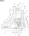
FIG. 3 is a view similar toFIG. 2 , and illustrates a structure of a comparative example of the present invention. -
FIG. 4 is a view similar toFIG. 2 , and illustrates a second example of an embodiment of the present invention. -
FIG. 1 andFIG. 2 illustrate a first example of an embodiment of the present invention. The toroidal continuously variable transmission 1 of this example is a double cavity type that includes arotating shaft 2, a pair ofoutside disks inside disk 4 that is an output disk, a plurality of power rollers (not illustrated), and apressing device 5. - The rotating
shaft 2 has a lubricatingoil flow path 6 penetrating the center portion in the axial direction, and adischarge port 7 that communicates with the outer-circumferential surface of the rotatingshaft 2 and the lubricatingoil flow path 6. In other words, the lubricating oil supplied from an oil source into the lubricatingoil flow path 6 is discharged from thedischarge port 7, and passes through anoil supply passage 19 and a branch hole, which will be described later, to a contact portion between the rolling surface of theroller 12, afirst cam surface 13 and asecond cam surface 15. Note that thedischarge port 7 may be provided at only one location in the circumferential direction of the rotatingshaft 2, or can be provided at a plurality of locations in the circumferential direction. Moreover, in the illustrated example, the opening portion of the lubricatingoil flow path 6 is covered by alid 8. - The pair of
outside disks ball splines 9 on both sides in the axial direction of the rotatingshaft 2 in a state in which the side surfaces in the axial direction that are toroidal curved surfaces with an arc shaped cross section face each other. Therefore, the pair ofoutside disks shaft 2. - The
inside disk 4 is provided at an intermediate portion in the axial direction of the rotatingshaft 2 in a state in which both side surfaces in the axial direction that are toroidal curved surface having an arc shaped cross section are opposed to the side surfaces in the axial direction of the pair ofoutside disks shaft 2. Theinside disk 4 has agear 10 on the outer-circumferential surface. - The circumferential surface of each of the power rollers is held between the side surfaces in the axial direction of the pair of
outside disks inside disk 4 in a state in which a peripheral surface of each of the power roller that is a spherical convex surface is in rolling contact with the side surfaces in the axial direction of the pair ofoutside disks inside disk 4. Note that, each of the power rollers is rotatably supported by a support member that is supported so as to be able to pivot around a pivot shaft that is located at a skewed position with respect to the rotatingshaft 2. - The
pressing device 5 is for pressing a firstoutside disk 3a, which is one of the pair ofoutside disks outside disk 3b, which is the other of the pair. In this example, thepressing device 5 is a loading cam type and includes a firstoutside disk 3a, acam plate 11, a plurality ofrollers 12 that are rolling bodies, and aretainer 29. - The first
outside disk 3a has a toroidal curved surface having an arc-shaped cross section on one side surface in the axial direction (the left side surface inFIG. 1 andFIG. 2 ), and has afirst cam surface 13, which is an uneven surface in the circumferential direction, on the other side surface in the axial direction (right side inFIG. 1 andFIG. 2 ). The firstoutside disk 3a is supported around the rotatingshaft 2 via aball spline 9 so as to be able to displace in the axial direction relative to the rotatingshaft 2, and so as to be able to rotate in synchronization with the rotatingshaft 2. - The
cam plate 11 has a substantially L-shaped cross section, includes acylindrical portion 14, and an outward facingflange portion 16 that is bent outward in the radial direction from the other end portion in the axial direction of thecylindrical portion 14 and has asecond cam surface 15 on one side surface in the axial direction that faces thefirst cam surface 13. - The
cylindrical portion 14 includes acylinder portion 17, aprojection 18, and anoil supply passage 19. Theprojection 18 is provided around the entire circumference so as to protrude inward in the radial direction from the inner-circumferential surface at one end portion in the axial direction of thecylinder portion 17. The other side surface in the axial direction of theprojection 18 is astep surface 38 facing in the other direction in the axial direction. In other words, the inner circumferential surface of an intermediate portion in the axial direction of thecylinder portion 17 and the inner-circumferential surface of theprojection 18 are connected by thestep surface 38. In addition, theprojection 18 has an inward facingflange portion 20 at one end portion in the axial direction, and projects further inward in the radial direction than a portion adjacent to the other side in the axial direction. Note that it is not always necessary to provide such aprojection 18 around the entire circumference. In other words, the projection may be configured to have a discontinuous portion, or may be configured to include protrusions provided at a plurality of positions in the circumferential direction. - The
oil supply passage 19 is provided in a radial manner at at least one position (preferably a plurality of positions) in the circumferential direction of an intermediate portion in the axial direction of thecylindrical portion 14 so as to penetrate thecylindrical portion 14 in the radial direction. Each of theoil supply passages 19 has an oil-passage hole 21 that communicates between the outer-circumferential surface and the inner-circumferential surface of thecylinder portion 17, and an oil-passage groove 22 provided on thestep surface 38 so as to be continuous with the oil-passage hole 21 in the radial direction, and to be recessed in one direction in the axial direction. In the present example, the oil-passage hole 21 and the oil-passage groove 22 of eachoil supply passage 19 are present on the same cylindrical surface. In other words, the oil-passage hole 21 is formed as a circular hole, and the oil-passage groove 22 is formed having an arc-shaped cross section. - Note that the oil supply passage is not limited to the above-described configuration, and various configurations may be adopted. More specifically, for example, the oil-passage hole and the oil-passage groove of the oil supply passage may be present on the same conical surface having an inside diameter that increases toward the outside in the radial direction. Alternatively, for example, the oil-passage hole of the oil supply passage may be a rectangular hole, and the oil-passage groove may have a rectangular cross section. Moreover, in this example, the
oil supply passage 19 is provided in the radial direction; however, theoil supply passage 19 may be provided in a direction in which theoil supply passage 19 is inclined in a direction toward one or the other in the axial direction toward the outside in the radial direction. - The
cam plate 11 is supported at an end portion of therotating shaft 2 via a support bearing 23 so as to be rotatable with respect to therotating shaft 2. In this example, the support bearing 23 is of an angular type, and a plurality ofballs 27 are arranged between aninner raceway 24 formed on the outer-circumferential surface of the end portion of therotating shaft 2 and anouter raceway 26 formed on the inner-circumferential surface of theouter ring 25 so as to be able to roll freely. Theouter race 25 is fitted inside the other end portion in the axial direction of thecylindrical portion 14 of thecam plate 11 so as to be able to transmit power and so that relative displacement in the axial direction is possible. More specifically, for example, the outer-circumferential surface of theouter ring 25 and the inner-circumferential surface of the other end portion in the axial direction of thecylindrical portion 14 engage by a spline engagement. - Moreover, a
disc spring 28 and aspacer 39 are sandwiched between one side surface in the axial direction of theouter ring 25 and the other side surface in the axial direction of theprojection 18. Thecam plate 11, theroller 12, and the firstoutside disk 3a are pressed toward the one side in the axial direction by thedisc spring 28, and at the same time, therotating shaft 2 and the secondoutside disk 3b are pulled toward the other side in the axial direction. With such a configuration, even when therotating shaft 2 is stopped, the surface pressure of a traction portion, which is a rolling contact portion between the circumferential surface of the power roller and one side surface in the axial direction of the pair ofoutside disks inside disk 4 may be maintained at the minimum required pressure. Therefore, the traction portion may start power transmission immediately after the start of operation of the toroidal continuously variable transmission 1 without the occurrence of excessive slippage. - Each
roller 12 has a short columnar shape with a dimension in the axial direction that is shorter than the diameter dimension. Eachroller 12 is such that the rolling surface that is the outer-circumferential surface is brought into rolling contact with thefirst cam surface 13 and thesecond cam surface 15, and is held between thefirst cam surface 13 and thesecond cam surface 15. In this example, therollers 12 are such that every set number of rollers (every three rollers in the illustrated example) are combined in a series, and in this state, are rotatably arranged inside pockets 30 that are arranged at a plurality of locations in the circumferential direction of theretainer 29. Each of therollers 12 that are combined in series may rotate independently, so it is possible to absorb a speed difference between the inner diameter sides and the outer diameter sides of thefirst cam surface 13 and thesecond cam surface 15. - The
retainer 29 has a ring shape as a whole and includes a pair ofrim portions column portions 32 that span between the pair ofrim portions rim portions column portions 32 adjacent in the circumferential direction is apocket 30 for rotatably holding therollers 12. - Of the pair of
rim portions rim portion 31a on the outer diameter side has a protrudingportion 33a that protrudes over the entire circumference further toward the one side in the axial direction than thecolumn portion 32. On the other hand, of the pair ofrim portions rim portion 31b on the inner diameter side has a protrudingportion 33b that protrudes over the entire circumference further toward the other side in the axial direction than thecolumn portion 32, and a projectingportion 40 protruding over the entire circumference further toward the one side in the axial direction than thecolumn portion 32. In the present example, the protrudingportion 33a on the outer diameter side engages with thefirst cam surface 13, and theprotrusion 33b on the inner diameter side engages with thesecond cam surface 15, making it possible to position theretainer 29 in the axial direction. On the other hand, therim portion 31b on the inner diameter side is externally fitted to thecylindrical portion 14 of thecam plate 11 with a clearance fit, and the inner-circumferential surface of therim portion 31b on the inner diameter side and the outer-circumferential surface of thecylindrical portion 14 are brought into close proximity to each other, and by opposing each other, it is possible to position theretainer 29 in the radial direction. - The
rim portion 31b on the inner diameter side has an oilretaining recess portion 34 on the outer diameter side and a plurality ofsupply holes retaining recess portion 34 on the outer diameter side is provided around the entire circumference of the inner-circumferential surface of a portion of therim portion 31b on the inner diameter side that spans from an intermediate portion in the axial direction existing on the inner diameter side of thecolumn portion 32 to the projectingportion 40 so as to face the opening on the outer diameter side of the oil-passage hole 21 that is open on the outer-circumferential surface of thecylinder portion 17. Note that the oilretaining recess portion 34 on the outer diameter side has a width dimension sufficient so as to always be capable of facing the opening on the outer diameter side of the oil-passage hole 21 in the radial direction regardless of the riding up position of theroller 12 on thefirst cam surface 13 and thesecond cam surface 15. - The
supply holes rim portion 31b on the inner diameter side so that the phase in the circumferential direction coincides with that of thepockets 30. Of each pair ofsupply holes supply hole 35a is formed in a direction toward the one side in the axial direction while going outward in the radial direction, and the opening on the inner diameter side opens to the bottom surface of the oilretaining recess portion 34 on the outer diameter side, and the opening on the outer diameter side opens to the outer-circumferential surface of the projectingportion 40. On the other hand, each of theother supply holes 35b is formed in a direction toward the other side in the axial direction while going toward the outside in the radial direction, and the opening on the inner diameter side opens to the bottom surface of the oilretaining recess portion 34 on the outer diameter side, and the opening on the outer diameter side opens to the outer-circumferential surface of the protrudingportion 33b on the inner diameter side. - During operation of the toroidal continuously variable transmission 1 having the configuration described above, the
cam plate 11 of thepressing device 5 is rotationally driven by a drive source such as an engine, a motor, or the like via adrive shaft 36. When thecam plate 11 is rotationally driven, each of therollers 12 rides up on convex portions of thefirst cam surface 13 and thesecond cam surface 15 so as to become strongly held between thefirst cam surface 13 and thesecond cam surface 15. In addition, the rotation of thecam plate 11 is transmitted to the firstoutside disk 3a via an engagement portion between the rolling surface of eachroller 12 and thefirst cam surface 13 and thesecond cam surface 15. As a result, each of the pair ofoutside disks outside disks inside disk 4 via the power rollers, and the rotation of theinside disk 4 is obtained from thegear 10. - Note that in a case of changing the gear ratio between the pair of
outside disks inside disk 4, the support members supporting the power rollers are displaced in the axial direction of the pivot shaft. This changes the direction of the force in the tangential direction acting on the traction portion. When the direction of the force in the tangential direction acting on the traction portion changes, the support member swings about the pivot shaft, and the positions of contact between the circumferential surface of the power roller, the one side surface in the axial direction of each of the pair ofoutside disks inside disk 4 changes. In this example, in a case where the circumferential surface of each of the power rollers is brought into rolling contact with the outside portion in the radial direction of each of the pair ofoutside disks inside disk 4, the gear ratio of the toroidal continuously variable transmission 1 is on the speed increasing side. On the other hand, in a case where the circumferential surface of each power roller is brought into rolling contact with the inside portion in the radial direction of each of the pair ofoutside disks inside disk 4, the gear ratio of the toroidal continuously variable transmission is changed to the decreasing speed side. - Moreover, lubricating oil that is supplied into the lubricating
oil flow path 6 of therotating shaft 2 is discharged from thedischarge port 7 by centrifugal force caused by the rotation of therotating shaft 2. The lubricating oil discharged from thedischarge port 7 is held in the oilretaining recess portion 37 on the inner diameter side defined by the inner-circumferential surface of the other side in the axial direction of theprojection 18, the other side surface in the axial direction of the inward facingflange portion 20, and one side surface in the axial direction of thedisc spring 28. The lubricating oil in the oilretaining recess portion 37 on the inner diameter side is taken into theoil supply passage 19 from the oil-passage groove 22, is discharged from the opening on the outer diameter side of the oil-passage hole 21 toward the oilretaining recess portion 34 on the outer diameter side of theretainer 29, and is held in the oilretaining recess portion 34 on the outer diameter side. Then, the lubricating oil in the oilretaining recess portion 34 on the outer diameter side is discharged toward the contact portions between the rolling surface of theroller 12, and thefirst cam surface 13 and thesecond cam surface 15 via thesupply holes roller 12, thefirst cam surface 13 and thesecond cam surface 15 is prevented. - In the toroidal continuously variable transmission 1 of the present example, each of the
oil supply passages 19 in thecam plate 11 includes an oil-passage hole 21 that communicates between the outer-circumferential surface and the inner-circumferential surface of thecylinder portion 17, and an oil-passage groove 22 provided so as to be continuous in the radial direction with the oil-passage hole 21, and so as to be recessed in the one direction in the axial direction from thestep surface 38, and providing theoil supply passage 19 prevents thecam plate 11 from having a thin portion having a small thickness. On the other hand, in the comparative example illustrated inFIG. 3 , theoil supply passage 19a is a through hole having an inner end portion in the radial direction that opens to the inner-circumferential surface of theprojection 18 and an outer end portion in the radial direction that opens to the outer-circumferential surface of thecylinder portion 17. Therefore, a portion of theprojection 18 of thecam plate 11 existing further on the other side in the axial direction than theoil supply passage 19a is athin portion 41 having a small thickness. In the present example, the thin portion having a small thickness does not exist in thecam plate 11, so the strength of thecam plate 11 may be increased as compared with the structure of the comparative example illustrated inFIG. 3 . Moreover, even in a case where thecam plate 11 is subjected to a heat treatment such as quenching or the like, it is possible to prevent the occurrence of cracking or the like in thecam plate 11. - Note that in this example, a case has been described in which the pair of
outside disks inside disk 4 is an output disk; however, in implementing the present invention, the inside disk may be an input disk and a pair of outside disks may be output disks. Moreover, in a toroidal continuously variable transmission in which the pressing device of the present invention is incorporated, a structure of a half toroidal type or a full toroidal type may be adopted. Furthermore, a toroidal continuously variable transmission in which the pressing device of the present invention is incorporated is not limited to the double cavity type, but may be a single cavity type. -
FIG. 4 illustrates a second example of an embodiment of the present invention. In this example, the entire opening on the inside in the radial direction of theoil supply passage 19b is opened to a portion of thecylinder portion 17 of thecylindrical portion 14 that is located further on the other side in the axial direction (the right side inFIG. 4 ) than thestep surface 38. In other words, theoil supply passage 19b is provided so as to penetrate in the radial direction a portion of thecylinder portion 17 located further on the other side in the axial direction than thestep surface 38. In the case of this example as well, thecam plate 11 may be made so that there is no thin portion with a small thickness, and the strength of thecam plate 11 may be increased compared with the structure of the comparative example illustrated inFIG. 3 . The configuration, operation and effect of the other parts are the same as those of the first example. -
- 1
- Toroidal continuously variable transmission
- 2
- Rotating shaft
- 3a, 3b
- Outside disk
- 4
- Inside disk
- 5
- Pressing device
- 6
- Lubricating oil flow path
- 7
- Discharge port
- 8
- Lid
- 9
- Ball spline
- 10
- Gear
- 11
- Cam plate
- 12
- Roller
- 13
- First cam surface
- 14
- Cylindrical portion
- 15
- Second cam surface
- 16
- Outward facing flange portion
- 17
- Cylinder portion
- 18
- Projection
- 19, 19a, 19b
- Oil supply passage
- 20
- Inward facing flange portion
- 21
- Oil-passage hole
- 22
- Oil-passage groove
- 23
- Support bearing
- 24
- Inner raceway
- 25
- Outer ring
- 26
- Outer raceway
- 27
- Ball
- 28
- Disc spring
- 29
- Retainer
- 30
- 31a, 31b
- Rim portion
- 32
- Column portion
- 33a, 33b
- Protruding portion
- 34
- Outer diameter side oil retaining recess portion
- 35a, 35b
- Supply hole
- 36
- Drive shaft
- 37
- Inner diameter side oil retaining recess portion
- 38
- Step surface
- 39
- Spacer
- 40
- Projecting portion
- 41
- Thin portion
Claims (2)
- A pressing device for a toroidal continuously variable transmission, comprising:a disk having a toroidal curved surface having an arc-shaped cross section on one side surface in an axial direction, and having a first cam surface configured by an uneven surface in a circumferential direction on an other side surface in the axial direction;a cam plate including a cylindrical portion, and an outward facing flange portion bent outward in a radial direction from an other end portion in the axial direction of the cylindrical portion, and having a second cam surface configured by an uneven surface in the circumferential direction on one side surface in the axial direction facing the first cam surface; anda plurality of rolling bodies held between the first cam surface and the second cam surface;the cylindrical portion having a cylinder portion, and a projection provided so as to project inward in the radial direction from the inner-circumferential surface on one end portion in the axial direction of the cylinder portion, and having a step surface facing in an other direction in the axial direction, and an oil supply passage penetrating the cylindrical portion in the radial direction; andat least a part of an opening on an inside in the radial direction of the oil supply passage opening to a portion of the inner-circumferential surface of the cylinder portion positioned further on an other side in the axial direction than the step surface.
- The pressing device for a toroidal continuously variable transmission according to claim 1, wherein
the oil supply passage has an oil-passage hole communicating between an outer-circumferential surface and the inner-circumferential surface of the cylinder portion, and an oil-passage groove provided so as to be continuous with the oil-passage hole in the radial direction and so as to be recessed from the step surface in one direction in the axial direction.
Applications Claiming Priority (2)
| Application Number | Priority Date | Filing Date | Title |
|---|---|---|---|
| JP2017220900A JP6908501B2 (en) | 2017-11-16 | 2017-11-16 | Pressing device for toroidal continuously variable transmission |
| PCT/JP2018/041349 WO2019098105A1 (en) | 2017-11-16 | 2018-11-07 | Pressing device for toroidal continuously variable transmission |
Publications (3)
| Publication Number | Publication Date |
|---|---|
| EP3712465A1 true EP3712465A1 (en) | 2020-09-23 |
| EP3712465A4 EP3712465A4 (en) | 2021-06-02 |
| EP3712465B1 EP3712465B1 (en) | 2023-01-18 |
Family
ID=66539651
Family Applications (1)
| Application Number | Title | Priority Date | Filing Date |
|---|---|---|---|
| EP18877491.3A Active EP3712465B1 (en) | 2017-11-16 | 2018-11-07 | Pressing device for toroidal continuously variable transmission |
Country Status (4)
| Country | Link |
|---|---|
| US (1) | US11384818B2 (en) |
| EP (1) | EP3712465B1 (en) |
| JP (1) | JP6908501B2 (en) |
| WO (1) | WO2019098105A1 (en) |
Families Citing this family (2)
| Publication number | Priority date | Publication date | Assignee | Title |
|---|---|---|---|---|
| WO2018174086A1 (en) * | 2017-03-21 | 2018-09-27 | 日本精工株式会社 | Pressing device for toroidal continuously variable transmission |
| WO2020179210A1 (en) | 2019-03-07 | 2020-09-10 | アドバンストマテリアルテクノロジーズ株式会社 | Film structure, piezoelectric film and superconductor film |
Family Cites Families (11)
| Publication number | Priority date | Publication date | Assignee | Title |
|---|---|---|---|---|
| JPH0137249Y2 (en) | 1985-10-24 | 1989-11-10 | ||
| JPH0672656B2 (en) * | 1989-03-31 | 1994-09-14 | 日産自動車株式会社 | Loading cam device for toroidal continuously variable transmission |
| JP2697261B2 (en) * | 1990-07-10 | 1998-01-14 | 日産自動車株式会社 | Friction wheel type continuously variable transmission |
| JPH06147283A (en) | 1992-11-04 | 1994-05-27 | Mazda Motor Corp | Toroidal type continuously variable transmission |
| JP3456267B2 (en) * | 1994-08-26 | 2003-10-14 | 日本精工株式会社 | Toroidal type continuously variable transmission |
| US6471617B1 (en) * | 1997-07-26 | 2002-10-29 | Zf Friedrichshafen Ag | Infinitely variable toroidal drive |
| US6592491B1 (en) | 1999-04-07 | 2003-07-15 | Nsk Ltd. | Toroidal type continuously variable transmission |
| DE19931087C2 (en) | 1999-07-06 | 2002-07-04 | Nsk Ltd | Cam disc for a continuously variable toroidal gear and method for producing the same |
| JP4254051B2 (en) * | 2000-11-15 | 2009-04-15 | 日本精工株式会社 | Toroidal continuously variable transmission |
| JP3783626B2 (en) | 2002-01-10 | 2006-06-07 | 日本精工株式会社 | Toroidal continuously variable transmission |
| US8469856B2 (en) * | 2008-08-26 | 2013-06-25 | Fallbrook Intellectual Property Company Llc | Continuously variable transmission |
-
2017
- 2017-11-16 JP JP2017220900A patent/JP6908501B2/en active Active
-
2018
- 2018-11-07 EP EP18877491.3A patent/EP3712465B1/en active Active
- 2018-11-07 WO PCT/JP2018/041349 patent/WO2019098105A1/en not_active Ceased
- 2018-11-07 US US16/763,674 patent/US11384818B2/en active Active
Also Published As
| Publication number | Publication date |
|---|---|
| US20200271200A1 (en) | 2020-08-27 |
| JP6908501B2 (en) | 2021-07-28 |
| US11384818B2 (en) | 2022-07-12 |
| EP3712465B1 (en) | 2023-01-18 |
| EP3712465A4 (en) | 2021-06-02 |
| JP2019090505A (en) | 2019-06-13 |
| WO2019098105A1 (en) | 2019-05-23 |
Similar Documents
| Publication | Publication Date | Title |
|---|---|---|
| US9005066B2 (en) | Motor assembly with speed reducer | |
| US11333225B2 (en) | Pressing device for toroidal continuously variable transmission | |
| EP3712465B1 (en) | Pressing device for toroidal continuously variable transmission | |
| JP6094319B2 (en) | Friction roller reducer | |
| US10167932B2 (en) | Loading cam device and friction roller-type speed reducer | |
| US20170108103A1 (en) | Integrated active limited slip differential | |
| US2123008A (en) | Power transmission mechanism | |
| JP6117991B2 (en) | Toroidal continuously variable transmission | |
| US20190277375A1 (en) | Toroidal continuously variable transmission | |
| JP2021089058A (en) | Thrust receiving structure of rotor | |
| JP5849645B2 (en) | Friction roller reducer | |
| JP6090502B2 (en) | One-way clutch and power generator | |
| JPH07174146A (en) | Thrust rolling bearing | |
| US20030130087A1 (en) | Toroidal-type continuously variable transmission | |
| JP2005155856A (en) | Planetary gear set | |
| JP3717347B2 (en) | Toroidal continuously variable transmission | |
| JP2006002882A (en) | Toroidal continuously variable transmission | |
| JP3705719B2 (en) | Toroidal continuously variable transmission | |
| JP2015075185A (en) | Single cavity type toroidal type continuously variable transmission | |
| JP2017141914A (en) | Friction roller reducer | |
| JP5982326B2 (en) | Toroidal continuously variable transmission | |
| JP2015227681A (en) | Friction roller transmission | |
| JP2007270988A (en) | Rolling bearing device | |
| JPS5854299B2 (en) | Friction roller transmission device | |
| JP2013024291A (en) | Speed reduction gear |
Legal Events
| Date | Code | Title | Description |
|---|---|---|---|
| STAA | Information on the status of an ep patent application or granted ep patent |
Free format text: STATUS: THE INTERNATIONAL PUBLICATION HAS BEEN MADE |
|
| PUAI | Public reference made under article 153(3) epc to a published international application that has entered the european phase |
Free format text: ORIGINAL CODE: 0009012 |
|
| STAA | Information on the status of an ep patent application or granted ep patent |
Free format text: STATUS: REQUEST FOR EXAMINATION WAS MADE |
|
| 17P | Request for examination filed |
Effective date: 20200514 |
|
| AK | Designated contracting states |
Kind code of ref document: A1 Designated state(s): AL AT BE BG CH CY CZ DE DK EE ES FI FR GB GR HR HU IE IS IT LI LT LU LV MC MK MT NL NO PL PT RO RS SE SI SK SM TR |
|
| AX | Request for extension of the european patent |
Extension state: BA ME |
|
| DAV | Request for validation of the european patent (deleted) | ||
| DAX | Request for extension of the european patent (deleted) | ||
| A4 | Supplementary search report drawn up and despatched |
Effective date: 20210503 |
|
| RIC1 | Information provided on ipc code assigned before grant |
Ipc: F16H 15/38 20060101AFI20210426BHEP Ipc: F16H 57/04 20100101ALI20210426BHEP |
|
| STAA | Information on the status of an ep patent application or granted ep patent |
Free format text: STATUS: EXAMINATION IS IN PROGRESS |
|
| 17Q | First examination report despatched |
Effective date: 20220127 |
|
| GRAP | Despatch of communication of intention to grant a patent |
Free format text: ORIGINAL CODE: EPIDOSNIGR1 |
|
| STAA | Information on the status of an ep patent application or granted ep patent |
Free format text: STATUS: GRANT OF PATENT IS INTENDED |
|
| INTG | Intention to grant announced |
Effective date: 20220901 |
|
| GRAS | Grant fee paid |
Free format text: ORIGINAL CODE: EPIDOSNIGR3 |
|
| GRAA | (expected) grant |
Free format text: ORIGINAL CODE: 0009210 |
|
| STAA | Information on the status of an ep patent application or granted ep patent |
Free format text: STATUS: THE PATENT HAS BEEN GRANTED |
|
| AK | Designated contracting states |
Kind code of ref document: B1 Designated state(s): AL AT BE BG CH CY CZ DE DK EE ES FI FR GB GR HR HU IE IS IT LI LT LU LV MC MK MT NL NO PL PT RO RS SE SI SK SM TR |
|
| REG | Reference to a national code |
Ref country code: GB Ref legal event code: FG4D |
|
| REG | Reference to a national code |
Ref country code: DE Ref legal event code: R096 Ref document number: 602018045611 Country of ref document: DE |
|
| REG | Reference to a national code |
Ref country code: CH Ref legal event code: EP |
|
| REG | Reference to a national code |
Ref country code: AT Ref legal event code: REF Ref document number: 1544878 Country of ref document: AT Kind code of ref document: T Effective date: 20230215 Ref country code: IE Ref legal event code: FG4D |
|
| REG | Reference to a national code |
Ref country code: LT Ref legal event code: MG9D |
|
| REG | Reference to a national code |
Ref country code: NL Ref legal event code: MP Effective date: 20230118 |
|
| REG | Reference to a national code |
Ref country code: AT Ref legal event code: MK05 Ref document number: 1544878 Country of ref document: AT Kind code of ref document: T Effective date: 20230118 |
|
| PG25 | Lapsed in a contracting state [announced via postgrant information from national office to epo] |
Ref country code: NL Free format text: LAPSE BECAUSE OF FAILURE TO SUBMIT A TRANSLATION OF THE DESCRIPTION OR TO PAY THE FEE WITHIN THE PRESCRIBED TIME-LIMIT Effective date: 20230118 |
|
| PG25 | Lapsed in a contracting state [announced via postgrant information from national office to epo] |
Ref country code: RS Free format text: LAPSE BECAUSE OF FAILURE TO SUBMIT A TRANSLATION OF THE DESCRIPTION OR TO PAY THE FEE WITHIN THE PRESCRIBED TIME-LIMIT Effective date: 20230118 Ref country code: PT Free format text: LAPSE BECAUSE OF FAILURE TO SUBMIT A TRANSLATION OF THE DESCRIPTION OR TO PAY THE FEE WITHIN THE PRESCRIBED TIME-LIMIT Effective date: 20230518 Ref country code: NO Free format text: LAPSE BECAUSE OF FAILURE TO SUBMIT A TRANSLATION OF THE DESCRIPTION OR TO PAY THE FEE WITHIN THE PRESCRIBED TIME-LIMIT Effective date: 20230418 Ref country code: LV Free format text: LAPSE BECAUSE OF FAILURE TO SUBMIT A TRANSLATION OF THE DESCRIPTION OR TO PAY THE FEE WITHIN THE PRESCRIBED TIME-LIMIT Effective date: 20230118 Ref country code: LT Free format text: LAPSE BECAUSE OF FAILURE TO SUBMIT A TRANSLATION OF THE DESCRIPTION OR TO PAY THE FEE WITHIN THE PRESCRIBED TIME-LIMIT Effective date: 20230118 Ref country code: HR Free format text: LAPSE BECAUSE OF FAILURE TO SUBMIT A TRANSLATION OF THE DESCRIPTION OR TO PAY THE FEE WITHIN THE PRESCRIBED TIME-LIMIT Effective date: 20230118 Ref country code: ES Free format text: LAPSE BECAUSE OF FAILURE TO SUBMIT A TRANSLATION OF THE DESCRIPTION OR TO PAY THE FEE WITHIN THE PRESCRIBED TIME-LIMIT Effective date: 20230118 Ref country code: AT Free format text: LAPSE BECAUSE OF FAILURE TO SUBMIT A TRANSLATION OF THE DESCRIPTION OR TO PAY THE FEE WITHIN THE PRESCRIBED TIME-LIMIT Effective date: 20230118 |
|
| PG25 | Lapsed in a contracting state [announced via postgrant information from national office to epo] |
Ref country code: SE Free format text: LAPSE BECAUSE OF FAILURE TO SUBMIT A TRANSLATION OF THE DESCRIPTION OR TO PAY THE FEE WITHIN THE PRESCRIBED TIME-LIMIT Effective date: 20230118 Ref country code: PL Free format text: LAPSE BECAUSE OF FAILURE TO SUBMIT A TRANSLATION OF THE DESCRIPTION OR TO PAY THE FEE WITHIN THE PRESCRIBED TIME-LIMIT Effective date: 20230118 Ref country code: IS Free format text: LAPSE BECAUSE OF FAILURE TO SUBMIT A TRANSLATION OF THE DESCRIPTION OR TO PAY THE FEE WITHIN THE PRESCRIBED TIME-LIMIT Effective date: 20230518 Ref country code: GR Free format text: LAPSE BECAUSE OF FAILURE TO SUBMIT A TRANSLATION OF THE DESCRIPTION OR TO PAY THE FEE WITHIN THE PRESCRIBED TIME-LIMIT Effective date: 20230419 Ref country code: FI Free format text: LAPSE BECAUSE OF FAILURE TO SUBMIT A TRANSLATION OF THE DESCRIPTION OR TO PAY THE FEE WITHIN THE PRESCRIBED TIME-LIMIT Effective date: 20230118 |
|
| REG | Reference to a national code |
Ref country code: DE Ref legal event code: R097 Ref document number: 602018045611 Country of ref document: DE |
|
| PG25 | Lapsed in a contracting state [announced via postgrant information from national office to epo] |
Ref country code: SM Free format text: LAPSE BECAUSE OF FAILURE TO SUBMIT A TRANSLATION OF THE DESCRIPTION OR TO PAY THE FEE WITHIN THE PRESCRIBED TIME-LIMIT Effective date: 20230118 Ref country code: RO Free format text: LAPSE BECAUSE OF FAILURE TO SUBMIT A TRANSLATION OF THE DESCRIPTION OR TO PAY THE FEE WITHIN THE PRESCRIBED TIME-LIMIT Effective date: 20230118 Ref country code: EE Free format text: LAPSE BECAUSE OF FAILURE TO SUBMIT A TRANSLATION OF THE DESCRIPTION OR TO PAY THE FEE WITHIN THE PRESCRIBED TIME-LIMIT Effective date: 20230118 Ref country code: DK Free format text: LAPSE BECAUSE OF FAILURE TO SUBMIT A TRANSLATION OF THE DESCRIPTION OR TO PAY THE FEE WITHIN THE PRESCRIBED TIME-LIMIT Effective date: 20230118 Ref country code: CZ Free format text: LAPSE BECAUSE OF FAILURE TO SUBMIT A TRANSLATION OF THE DESCRIPTION OR TO PAY THE FEE WITHIN THE PRESCRIBED TIME-LIMIT Effective date: 20230118 |
|
| PLBE | No opposition filed within time limit |
Free format text: ORIGINAL CODE: 0009261 |
|
| STAA | Information on the status of an ep patent application or granted ep patent |
Free format text: STATUS: NO OPPOSITION FILED WITHIN TIME LIMIT |
|
| PG25 | Lapsed in a contracting state [announced via postgrant information from national office to epo] |
Ref country code: SK Free format text: LAPSE BECAUSE OF FAILURE TO SUBMIT A TRANSLATION OF THE DESCRIPTION OR TO PAY THE FEE WITHIN THE PRESCRIBED TIME-LIMIT Effective date: 20230118 |
|
| 26N | No opposition filed |
Effective date: 20231019 |
|
| PG25 | Lapsed in a contracting state [announced via postgrant information from national office to epo] |
Ref country code: SI Free format text: LAPSE BECAUSE OF FAILURE TO SUBMIT A TRANSLATION OF THE DESCRIPTION OR TO PAY THE FEE WITHIN THE PRESCRIBED TIME-LIMIT Effective date: 20230118 |
|
| PG25 | Lapsed in a contracting state [announced via postgrant information from national office to epo] |
Ref country code: IT Free format text: LAPSE BECAUSE OF FAILURE TO SUBMIT A TRANSLATION OF THE DESCRIPTION OR TO PAY THE FEE WITHIN THE PRESCRIBED TIME-LIMIT Effective date: 20230118 |
|
| REG | Reference to a national code |
Ref country code: CH Ref legal event code: PL |
|
| PG25 | Lapsed in a contracting state [announced via postgrant information from national office to epo] |
Ref country code: MC Free format text: LAPSE BECAUSE OF FAILURE TO SUBMIT A TRANSLATION OF THE DESCRIPTION OR TO PAY THE FEE WITHIN THE PRESCRIBED TIME-LIMIT Effective date: 20230118 |
|
| PG25 | Lapsed in a contracting state [announced via postgrant information from national office to epo] |
Ref country code: LU Free format text: LAPSE BECAUSE OF NON-PAYMENT OF DUE FEES Effective date: 20231107 |
|
| PG25 | Lapsed in a contracting state [announced via postgrant information from national office to epo] |
Ref country code: CH Free format text: LAPSE BECAUSE OF NON-PAYMENT OF DUE FEES Effective date: 20231130 |
|
| PG25 | Lapsed in a contracting state [announced via postgrant information from national office to epo] |
Ref country code: MC Free format text: LAPSE BECAUSE OF FAILURE TO SUBMIT A TRANSLATION OF THE DESCRIPTION OR TO PAY THE FEE WITHIN THE PRESCRIBED TIME-LIMIT Effective date: 20230118 Ref country code: LU Free format text: LAPSE BECAUSE OF NON-PAYMENT OF DUE FEES Effective date: 20231107 Ref country code: CH Free format text: LAPSE BECAUSE OF NON-PAYMENT OF DUE FEES Effective date: 20231130 |
|
| REG | Reference to a national code |
Ref country code: BE Ref legal event code: MM Effective date: 20231130 |
|
| REG | Reference to a national code |
Ref country code: IE Ref legal event code: MM4A |
|
| PG25 | Lapsed in a contracting state [announced via postgrant information from national office to epo] |
Ref country code: IE Free format text: LAPSE BECAUSE OF NON-PAYMENT OF DUE FEES Effective date: 20231107 |
|
| PG25 | Lapsed in a contracting state [announced via postgrant information from national office to epo] |
Ref country code: BE Free format text: LAPSE BECAUSE OF NON-PAYMENT OF DUE FEES Effective date: 20231130 |
|
| PG25 | Lapsed in a contracting state [announced via postgrant information from national office to epo] |
Ref country code: IE Free format text: LAPSE BECAUSE OF NON-PAYMENT OF DUE FEES Effective date: 20231107 Ref country code: BE Free format text: LAPSE BECAUSE OF NON-PAYMENT OF DUE FEES Effective date: 20231130 |
|
| PG25 | Lapsed in a contracting state [announced via postgrant information from national office to epo] |
Ref country code: BG Free format text: LAPSE BECAUSE OF FAILURE TO SUBMIT A TRANSLATION OF THE DESCRIPTION OR TO PAY THE FEE WITHIN THE PRESCRIBED TIME-LIMIT Effective date: 20230118 |
|
| PG25 | Lapsed in a contracting state [announced via postgrant information from national office to epo] |
Ref country code: BG Free format text: LAPSE BECAUSE OF FAILURE TO SUBMIT A TRANSLATION OF THE DESCRIPTION OR TO PAY THE FEE WITHIN THE PRESCRIBED TIME-LIMIT Effective date: 20230118 |
|
| PG25 | Lapsed in a contracting state [announced via postgrant information from national office to epo] |
Ref country code: CY Free format text: LAPSE BECAUSE OF FAILURE TO SUBMIT A TRANSLATION OF THE DESCRIPTION OR TO PAY THE FEE WITHIN THE PRESCRIBED TIME-LIMIT; INVALID AB INITIO Effective date: 20181107 |
|
| PG25 | Lapsed in a contracting state [announced via postgrant information from national office to epo] |
Ref country code: HU Free format text: LAPSE BECAUSE OF FAILURE TO SUBMIT A TRANSLATION OF THE DESCRIPTION OR TO PAY THE FEE WITHIN THE PRESCRIBED TIME-LIMIT; INVALID AB INITIO Effective date: 20181107 |
|
| PGFP | Annual fee paid to national office [announced via postgrant information from national office to epo] |
Ref country code: FR Payment date: 20250930 Year of fee payment: 8 |
|
| PG25 | Lapsed in a contracting state [announced via postgrant information from national office to epo] |
Ref country code: TR Free format text: LAPSE BECAUSE OF FAILURE TO SUBMIT A TRANSLATION OF THE DESCRIPTION OR TO PAY THE FEE WITHIN THE PRESCRIBED TIME-LIMIT Effective date: 20230118 |
|
| PGFP | Annual fee paid to national office [announced via postgrant information from national office to epo] |
Ref country code: DE Payment date: 20250930 Year of fee payment: 8 |
|
| PGFP | Annual fee paid to national office [announced via postgrant information from national office to epo] |
Ref country code: GB Payment date: 20251001 Year of fee payment: 8 |