EP3712440A1 - Turbocharger compressor housing - Google Patents
Turbocharger compressor housing Download PDFInfo
- Publication number
- EP3712440A1 EP3712440A1 EP20159325.8A EP20159325A EP3712440A1 EP 3712440 A1 EP3712440 A1 EP 3712440A1 EP 20159325 A EP20159325 A EP 20159325A EP 3712440 A1 EP3712440 A1 EP 3712440A1
- Authority
- EP
- European Patent Office
- Prior art keywords
- crankcase ventilation
- compressor housing
- compressor
- inlet
- turbocharger compressor
- Prior art date
- Legal status (The legal status is an assumption and is not a legal conclusion. Google has not performed a legal analysis and makes no representation as to the accuracy of the status listed.)
- Granted
Links
Images

Classifications
-
- F—MECHANICAL ENGINEERING; LIGHTING; HEATING; WEAPONS; BLASTING
- F04—POSITIVE - DISPLACEMENT MACHINES FOR LIQUIDS; PUMPS FOR LIQUIDS OR ELASTIC FLUIDS
- F04D—NON-POSITIVE-DISPLACEMENT PUMPS
- F04D29/00—Details, component parts, or accessories
- F04D29/40—Casings; Connections of working fluid
- F04D29/42—Casings; Connections of working fluid for radial or helico-centrifugal pumps
- F04D29/4206—Casings; Connections of working fluid for radial or helico-centrifugal pumps especially adapted for elastic fluid pumps
- F04D29/4213—Casings; Connections of working fluid for radial or helico-centrifugal pumps especially adapted for elastic fluid pumps suction ports
-
- F—MECHANICAL ENGINEERING; LIGHTING; HEATING; WEAPONS; BLASTING
- F01—MACHINES OR ENGINES IN GENERAL; ENGINE PLANTS IN GENERAL; STEAM ENGINES
- F01M—LUBRICATING OF MACHINES OR ENGINES IN GENERAL; LUBRICATING INTERNAL COMBUSTION ENGINES; CRANKCASE VENTILATING
- F01M13/00—Crankcase ventilating or breathing
- F01M13/02—Crankcase ventilating or breathing by means of additional source of positive or negative pressure
-
- F—MECHANICAL ENGINEERING; LIGHTING; HEATING; WEAPONS; BLASTING
- F04—POSITIVE - DISPLACEMENT MACHINES FOR LIQUIDS; PUMPS FOR LIQUIDS OR ELASTIC FLUIDS
- F04D—NON-POSITIVE-DISPLACEMENT PUMPS
- F04D29/00—Details, component parts, or accessories
- F04D29/40—Casings; Connections of working fluid
- F04D29/403—Casings; Connections of working fluid especially adapted for elastic fluid pumps
-
- F—MECHANICAL ENGINEERING; LIGHTING; HEATING; WEAPONS; BLASTING
- F01—MACHINES OR ENGINES IN GENERAL; ENGINE PLANTS IN GENERAL; STEAM ENGINES
- F01D—NON-POSITIVE DISPLACEMENT MACHINES OR ENGINES, e.g. STEAM TURBINES
- F01D25/00—Component parts, details, or accessories, not provided for in, or of interest apart from, other groups
- F01D25/24—Casings; Casing parts, e.g. diaphragms, casing fastenings
-
- F—MECHANICAL ENGINEERING; LIGHTING; HEATING; WEAPONS; BLASTING
- F01—MACHINES OR ENGINES IN GENERAL; ENGINE PLANTS IN GENERAL; STEAM ENGINES
- F01M—LUBRICATING OF MACHINES OR ENGINES IN GENERAL; LUBRICATING INTERNAL COMBUSTION ENGINES; CRANKCASE VENTILATING
- F01M13/00—Crankcase ventilating or breathing
-
- F—MECHANICAL ENGINEERING; LIGHTING; HEATING; WEAPONS; BLASTING
- F02—COMBUSTION ENGINES; HOT-GAS OR COMBUSTION-PRODUCT ENGINE PLANTS
- F02C—GAS-TURBINE PLANTS; AIR INTAKES FOR JET-PROPULSION PLANTS; CONTROLLING FUEL SUPPLY IN AIR-BREATHING JET-PROPULSION PLANTS
- F02C6/00—Plural gas-turbine plants; Combinations of gas-turbine plants with other apparatus; Adaptations of gas-turbine plants for special use
- F02C6/04—Gas-turbine plants providing heated or pressurised working fluid for other apparatus, e.g. without mechanical power output
- F02C6/10—Gas-turbine plants providing heated or pressurised working fluid for other apparatus, e.g. without mechanical power output supplying working fluid to a user, e.g. a chemical process, which returns working fluid to a turbine of the plant
- F02C6/12—Turbochargers, i.e. plants for augmenting mechanical power output of internal-combustion piston engines by increase of charge pressure
-
- F—MECHANICAL ENGINEERING; LIGHTING; HEATING; WEAPONS; BLASTING
- F02—COMBUSTION ENGINES; HOT-GAS OR COMBUSTION-PRODUCT ENGINE PLANTS
- F02M—SUPPLYING COMBUSTION ENGINES IN GENERAL WITH COMBUSTIBLE MIXTURES OR CONSTITUENTS THEREOF
- F02M25/00—Engine-pertinent apparatus for adding non-fuel substances or small quantities of secondary fuel to combustion-air, main fuel or fuel-air mixture
- F02M25/06—Engine-pertinent apparatus for adding non-fuel substances or small quantities of secondary fuel to combustion-air, main fuel or fuel-air mixture adding lubricant vapours
-
- F—MECHANICAL ENGINEERING; LIGHTING; HEATING; WEAPONS; BLASTING
- F02—COMBUSTION ENGINES; HOT-GAS OR COMBUSTION-PRODUCT ENGINE PLANTS
- F02M—SUPPLYING COMBUSTION ENGINES IN GENERAL WITH COMBUSTIBLE MIXTURES OR CONSTITUENTS THEREOF
- F02M35/00—Combustion-air cleaners, air intakes, intake silencers, or induction systems specially adapted for, or arranged on, internal-combustion engines
- F02M35/10—Air intakes; Induction systems
- F02M35/10209—Fluid connections to the air intake system; their arrangement of pipes, valves or the like
- F02M35/10222—Exhaust gas recirculation [EGR]; Positive crankcase ventilation [PCV]; Additional air admission, lubricant or fuel vapour admission
-
- F—MECHANICAL ENGINEERING; LIGHTING; HEATING; WEAPONS; BLASTING
- F02—COMBUSTION ENGINES; HOT-GAS OR COMBUSTION-PRODUCT ENGINE PLANTS
- F02M—SUPPLYING COMBUSTION ENGINES IN GENERAL WITH COMBUSTIBLE MIXTURES OR CONSTITUENTS THEREOF
- F02M35/00—Combustion-air cleaners, air intakes, intake silencers, or induction systems specially adapted for, or arranged on, internal-combustion engines
- F02M35/10—Air intakes; Induction systems
- F02M35/10242—Devices or means connected to or integrated into air intakes; Air intakes combined with other engine or vehicle parts
- F02M35/10268—Heating, cooling or thermal insulating means
-
- F—MECHANICAL ENGINEERING; LIGHTING; HEATING; WEAPONS; BLASTING
- F04—POSITIVE - DISPLACEMENT MACHINES FOR LIQUIDS; PUMPS FOR LIQUIDS OR ELASTIC FLUIDS
- F04D—NON-POSITIVE-DISPLACEMENT PUMPS
- F04D27/00—Control, e.g. regulation, of pumps, pumping installations or pumping systems specially adapted for elastic fluids
- F04D27/02—Surge control
- F04D27/0207—Surge control by bleeding, bypassing or recycling fluids
- F04D27/0238—Details or means for fluid reinjection
-
- F—MECHANICAL ENGINEERING; LIGHTING; HEATING; WEAPONS; BLASTING
- F04—POSITIVE - DISPLACEMENT MACHINES FOR LIQUIDS; PUMPS FOR LIQUIDS OR ELASTIC FLUIDS
- F04D—NON-POSITIVE-DISPLACEMENT PUMPS
- F04D29/00—Details, component parts, or accessories
- F04D29/02—Selection of particular materials
- F04D29/023—Selection of particular materials especially adapted for elastic fluid pumps
-
- F—MECHANICAL ENGINEERING; LIGHTING; HEATING; WEAPONS; BLASTING
- F04—POSITIVE - DISPLACEMENT MACHINES FOR LIQUIDS; PUMPS FOR LIQUIDS OR ELASTIC FLUIDS
- F04D—NON-POSITIVE-DISPLACEMENT PUMPS
- F04D29/00—Details, component parts, or accessories
- F04D29/58—Cooling; Heating; Diminishing heat transfer
- F04D29/582—Cooling; Heating; Diminishing heat transfer specially adapted for elastic fluid pumps
-
- F—MECHANICAL ENGINEERING; LIGHTING; HEATING; WEAPONS; BLASTING
- F01—MACHINES OR ENGINES IN GENERAL; ENGINE PLANTS IN GENERAL; STEAM ENGINES
- F01M—LUBRICATING OF MACHINES OR ENGINES IN GENERAL; LUBRICATING INTERNAL COMBUSTION ENGINES; CRANKCASE VENTILATING
- F01M13/00—Crankcase ventilating or breathing
- F01M13/0011—Breather valves
- F01M2013/0027—Breather valves with a de-icing or defrosting system
-
- F—MECHANICAL ENGINEERING; LIGHTING; HEATING; WEAPONS; BLASTING
- F01—MACHINES OR ENGINES IN GENERAL; ENGINE PLANTS IN GENERAL; STEAM ENGINES
- F01M—LUBRICATING OF MACHINES OR ENGINES IN GENERAL; LUBRICATING INTERNAL COMBUSTION ENGINES; CRANKCASE VENTILATING
- F01M13/00—Crankcase ventilating or breathing
- F01M13/02—Crankcase ventilating or breathing by means of additional source of positive or negative pressure
- F01M13/021—Crankcase ventilating or breathing by means of additional source of positive or negative pressure of negative pressure
- F01M2013/027—Crankcase ventilating or breathing by means of additional source of positive or negative pressure of negative pressure with a turbo charger or compressor
-
- F—MECHANICAL ENGINEERING; LIGHTING; HEATING; WEAPONS; BLASTING
- F05—INDEXING SCHEMES RELATING TO ENGINES OR PUMPS IN VARIOUS SUBCLASSES OF CLASSES F01-F04
- F05B—INDEXING SCHEME RELATING TO WIND, SPRING, WEIGHT, INERTIA OR LIKE MOTORS, TO MACHINES OR ENGINES FOR LIQUIDS COVERED BY SUBCLASSES F03B, F03D AND F03G
- F05B2220/00—Application
- F05B2220/40—Application in turbochargers
-
- F—MECHANICAL ENGINEERING; LIGHTING; HEATING; WEAPONS; BLASTING
- F05—INDEXING SCHEMES RELATING TO ENGINES OR PUMPS IN VARIOUS SUBCLASSES OF CLASSES F01-F04
- F05D—INDEXING SCHEME FOR ASPECTS RELATING TO NON-POSITIVE-DISPLACEMENT MACHINES OR ENGINES, GAS-TURBINES OR JET-PROPULSION PLANTS
- F05D2220/00—Application
- F05D2220/40—Application in turbochargers
-
- F—MECHANICAL ENGINEERING; LIGHTING; HEATING; WEAPONS; BLASTING
- F05—INDEXING SCHEMES RELATING TO ENGINES OR PUMPS IN VARIOUS SUBCLASSES OF CLASSES F01-F04
- F05D—INDEXING SCHEME FOR ASPECTS RELATING TO NON-POSITIVE-DISPLACEMENT MACHINES OR ENGINES, GAS-TURBINES OR JET-PROPULSION PLANTS
- F05D2230/00—Manufacture
- F05D2230/50—Building or constructing in particular ways
- F05D2230/53—Building or constructing in particular ways by integrally manufacturing a component, e.g. by milling from a billet or one piece construction
Definitions
- the present disclosure relates to turbocharger compressor housing and is particularly, although not exclusively, concerned with a turbocharger compressor housing configured to reduce freezing of crankcase ventilation gases.
- Engines e.g. for motor vehicles, often comprise a crankcase ventilation system configured to extract gases, e.g. blow-by gases, from inside the crankcase.
- gases e.g. blow-by gases
- the gases that are extracted from the crankcase may be reintroduced into the intake system to be drawn back into the engine cylinders.
- crankcase ventilation gases In cold ambient temperatures, water within the crankcase ventilation gases can begin to freeze at or close to the point at which they are reintroduced into the intake system. Freezing of the crankcase ventilation gases can block the crankcase ventilation system, leading to a build-up of blow-by gases within the crankcase, which is undesirable.
- a previously proposed engine assembly 2 comprises an engine 4 including a crankcase 6, and an intake system 10.
- the intake system comprises an intake duct 12, a turbocharger compressor 14 and an intake resonator 16 for damping vibrations of the inlet gases within the intake duct 12 at a desired frequency, e.g. at which it is desirable to reduce noise within the intake system.
- the engine assembly 2 further comprises a crankcase ventilation system 20 comprising a crankcase ventilation valve 22 coupled to the crankcase 6, and a crankcase ventilation duct 24 for carrying extracted crankcase ventilation gases from the crankcase ventilation valve 22 to the intake duct 12.
- the pressure within the intake duct 12 may be less than the pressure within the crankcase 6, and hence, blow-by gases within the crankcase 6 may be drawn through the crankcase ventilation valve 22 and the crankcase ventilation duct 24 into the intake duct 12.
- the intake duct 12 comprises a spigot 13 formed on the intake duct.
- the crankcase ventilation duct 24 is fluidically coupled to the intake duct 12 at the spigot 13 and the crankcase ventilation gases are introduced into the intake duct 12 via the spigot 13.
- crankcase ventilation system may further comprise a heater 26 configured to heat the crankcase ventilation duct 24 to raise the temperature of the crankcase ventilation gases and reduce the risk of water within the crankcase ventilation gases freezing.
- a turbocharger compressor housing for a motor vehicle, the housing comprising:
- the compressor inlet duct portion may be integrally formed with the compressor housing portion.
- the compressor housing portion, compressor inlet duct portion and the crankcase ventilation pipe may be a one-piece component.
- the turbocharger housing may be a one-piece metal component.
- the pipe may comprise an inlet opening, an outlet opening and a duct portion extending between the inlet opening and the outlet opening.
- the duct portion e.g. a wall of the duct portion, may be in contact, e.g. in direct contact, with, connected, e.g. directly connected, to or may be integrally formed with the compressor housing portion, e.g. a wall of the compressor housing portion, e.g. at a position between the inlet opening and the outlet opening of the pipe.
- a surface forming the duct portion e.g. the wall of the duct portion, may be in contact, e.g. in direct contact, with or may be joined directly with a surface forming a wall of the compressor housing portion, e.g. at a position on the duct portion between the inlet opening and the outlet opening of the pipe.
- the compressor housing portion may at least partially define an outlet volume, e.g. an outlet flow passage, of the turbocharger compressor, such as an outlet diffuser, volute or scroll.
- a portion of the turbocharger compressor housing may form a wall between the duct portion and the outlet volume.
- the duct portion may be formed by a first side of the wall and an outlet volume or outlet flow passage of the compressor housing portion may be formed by a second side of the wall, e.g. opposite the first side.
- the turbocharger compressor housing may further comprise a crankcase ventilation inlet chamber extending about the compressor intake duct.
- the crankcase ventilation inlet chamber may be in fluidic communication with the inlet of the turbocharger compressor.
- the pipe may be in fluidic communication with the crankcase ventilation inlet chamber, e.g. via the intake duct and/or the compressor housing portion.
- a passage may be formed between the crankcase ventilation inlet chamber and the compressor inlet duct portion, e.g. in an inner wall of the chamber.
- the passage may be formed at an opposite end of the crankcase ventilation inlet chamber to an opening of the pipe into the crankcase ventilation inlet chamber.
- At least a portion of a wall of the crankcase ventilation inlet chamber may be formed by the compressor inlet duct portion and/or the compressor housing portion, e.g. such that crankcase ventilation gases within the crankcase ventilation inlet chamber are in contact with the wall of the compressor intake duct and/or the compressor housing portion.
- an inner wall, e.g. an inner radial wall, of the crankcase ventilation inlet chamber may be formed by a wall of the compressor inlet duct portion.
- An axial end wall and/or an outer, e.g. radially outer, wall of the crankcase ventilation inlet chamber may be at least partially formed by the compressor housing portion.
- a passage is formed between the crankcase ventilation inlet chamber and the compressor intake duct or the compressor housing portion.
- An opening of the passage into the crankcase ventilation inlet chamber may be spaced apart from an opening of the pipe into the crankcase ventilation inlet chamber along a wall of the of the crankcase ventilation inlet chamber formed by the compressor intake duct and/or the compressor housing portion.
- the turbocharger compressor housing may further comprise a wall portion extending at least partially about the controller intake duct.
- An outer, e.g. radially outer, wall of the crankcase ventilation inlet chamber may be at least partially formed by the wall portion.
- the wall portion may be integrally formed with the compressor housing portion.
- the crankcase ventilation inlet chamber may be configured to damp pressure variations in the inlet air arriving at the compressor intake duct.
- the volume of the crankcase ventilation inlet chamber may be tuned to act as an inlet resonator.
- a turbocharger compressor housing comprising:
- a turbocharger compressor housing for a motor vehicle, the housing comprising:
- An intake assembly may comprise the above mentioned turbocharger compressor housing and an intake duct in fluidic communication with the compressor intake duct.
- a wall of the crankcase ventilation inlet chamber may be at least partially formed by the intake duct.
- an axial end wall of the crankcase ventilation inlet chamber may be at least partially formed by the intake duct.
- the intake duct may comprise a duct portion and a connector coupled to or integrally formed with the duct portion.
- the wall of the crankcase ventilation inlet chamber may be at least partially formed by the connector of the intake duct.
- At least a portion of an outer wall of the crankcase ventilation inlet chamber may be formed by the intake duct, e.g. a radially outer wall.
- a motor vehicle may comprise the above-mentioned turbocharger compressor housing or the above-mentioned intake assembly.
- an engine assembly 100 for a motor vehicle comprises an engine 110, a crankcase ventilation system 120 and an intake system 130.
- the engine 110 is similar to the engine 4 and comprises a crankcase 112.
- the crankcase ventilation system 120 is similar to the crankcase ventilation system 20 and comprises a crankcase ventilation valve 122, in fluidic communication with the interior of the crankcase 112, and a ventilation duct 124 for carrying extracted crankcase ventilation gases from the valve 122 to be reintroduced into the intake system 130, as described below.
- the intake system 130 comprises turbocharger compressor assembly 200 and an intake duct 132 for carrying intake gases from an air inlet 134 to an inlet 202 of a turbocharger compressor, e.g. a compressor rotor 210 of the turbocharger compressor assembly 200.
- the intake system 130 may further comprise an intake resonator 136 that is similar to the intake resonator 16 described above.
- the turbocharger compressor assembly 200 comprises the turbocharger compressor, e.g. the compressor rotor 210, and a turbocharger compressor housing 220.
- the turbocharger compressor housing 220 defines the turbocharger compressor inlet 202 and is configured to house the compressor rotor 210.
- turbocharger compressor assembly is depicted as an axial flow machine.
- turbocharger compressor may be a radial or mixed flow machine, e.g. an axial-to-radial flow machine, as depicted in Figure 3a .
- the intake system 130 differs from the intake system 10 depicted in Figure 1 in that the intake resonator 136 does not comprise a spigot for introducing the crankcase ventilation gases into the intake system 130. Instead, a crankcase ventilation pipe, e.g. a crankcase ventilation spigot 222, is formed on the turbocharger compressor assembly 200 for the crankcase ventilation gases to be introduced into the intake system. As shown in Figure 2 , the crankcase ventilation spigot 222 is formed on the turbocharger compressor housing 220.
- a crankcase ventilation pipe e.g. a crankcase ventilation spigot 222
- the crankcase ventilation spigot 222 may be formed integrally with the turbocharger compressor housing 220.
- the turbocharger compressor housing comprises a compressor housing portion 224, configured to house at least a portion of the turbocharger compressor, e.g. the rotor 210 of the turbocharger compressor, and a compressor inlet duct portion 226 for carrying intake gases from the intake duct 132 to the inlet 202 of the turbocharger compressor.
- the crankcase ventilation spigot 222 may be formed integrally with the compressor housing portion 224 and/or the compressor inlet duct portion 226. As depicted, the compressor housing portion 224, the compressor inlet duct portion 226 and the crankcase ventilation spigot 222 may be formed integrally with one another such that the turbocharger compressor housing 220 is a one-piece component. For example, the turbocharger compressor housing 220 may be a one-piece cast component.
- the crankcase ventilation spigot 222 may be formed from the same material as the compressor housing portion 224 and/or the compressor inlet duct portion 226.
- the crankcase ventilation spigot 222 may be manufactured from a metal material. Accordingly, heat may be transferred from the compressor housing portion 224 to the crankcase ventilation spigot 222 through heat conduction more effectively than if the crankcase ventilation spigot 222 was manufactured from a different material.
- the compressor housing portion 224 may at least partially define an outlet flow passage of the turbocharger compressor.
- the compressor housing portion 224 may at least partially define an outlet volume 224a, e.g. a diffuser, volute or scroll of the turbocharger compressor. Gases within the outlet volume may have been heated by virtue of the action of the turbocharger compressor.
- the compressor housing portion 224 may be heated by the gases within the outlet volume 224a.
- the crankcase ventilation spigot 222 comprises an inlet opening 222a, for receiving the crankcase ventilation gases from the crankcase ventilation duct 124, an outlet opening 222b, though which the crankcase ventilation gases enter the compressor inlet duct portion 226 or compressor housing portion 224, and a duct portion 222c extending between the inlet and outlet openings 222a, 222b.
- the crankcase ventilation spigot 222 may be arranged such that a wall of the duct portion 222c is in contact with or is integrally formed with the compressor housing portion 224.
- the wall of the duct portion 222c may be in contact with or integrally formed with a part of the compressor housing portion 224 forming a wall of the compressor outlet volume 224a.
- the duct portion 222c may be in contact, e.g. in direct contact, with or connected, e.g. directly connected, to the compressor housing portion 224, e.g. a wall of the compressor housing portion, at a position on the duct portion 222c between the inlet opening and the inlet opening 222a and the outlet opening 222b.
- the duct portion 222c may be in contact, e.g. in direct contact, with or connected, e.g. directly connected, to the compressor housing portion, e.g. a wall of the compressor housing portion, over a length of the duct portion 222c extending from or proximate to the outlet opening 222b towards the inlet opening 222a
- crankcase ventilation spigot 222 may be arranged such that the outlet opening 222b is adjacent, e.g. immediately adjacent, to the inlet 202 of the turbocharger compressor.
- the turbocharger compressor assembly 200 may comprise a crankcase ventilation inlet chamber 230.
- the crankcase ventilation spigot 222 is in fluidic communication with the crankcase ventilation inlet chamber 230 and the crankcase ventilation gases are introduced into the crankcase ventilation inlet chamber 230 before flowing from the crankcase ventilation inlet chamber 230 into the compressor inlet duct portion 226 or compressor housing portion 224, e.g. via a passage 240 formed between the crankcase ventilation inlet chamber 230 and the compressor inlet duct portion 226 or compressor housing portion 224.
- crankcase ventilation inlet chamber 230 is arranged about the turbocharger compressor inlet 202.
- the crankcase ventilation inlet chamber 230 may be arranged about the compressor inlet duct portion 226.
- the crankcase ventilation inlet chamber 30 may comprise a toroidal volume defined about an axis that is substantially aligned with a central axis of the turbocharger compressor inlet duct portion 226, e.g. the direction of the flow of inlet gases into the turbocharger compressor.
- At least a portion of a wall forming the crankcase ventilation inlet chamber 230 may be formed by, or integrally formed with, the compressor inlet duct portion 226 and/or the compressor housing portion 224.
- an inner, e.g. radially inner, wall 232 of the crankcase ventilation inlet chamber 230 may be formed by the compressor inlet duct portion 226.
- a first end wall 234, e.g. at a first axial end of the crankcase ventilation inlet chamber 230, may be formed by the compressor housing portion 224.
- the compressor housing portion 224 may be heated by the gases within the outlet volume 224a of the compressor.
- the crankcase ventilation gases within the crankcase ventilation inlet chamber 230, which are in contact with the first end wall 234, may therefore be heated.
- the compressor inlet duct portion 226 is in thermal communication with the compressor housing portion 224 and is heated by the gases within the compressor outlet volume 224a through thermal conduction, e.g. via the material of the compressor housing portion 224. Accordingly, the crankcase ventilation gases within the crankcase ventilation inlet chamber 230, which are in contact with the inner wall 232, may be heated.
- the outlet opening 222b of the crankcase ventilation spigot 222 may be positioned at a first end, e.g. axial end, of the crankcase ventilation inlet chamber 230, e.g. adjacent to the first end wall 234.
- An opening 242 of the passage 240 into the crankcase ventilation inlet chamber 230 may be spaced apart from outlet opening 222b along a length of a wall of the crankcase ventilation inlet chamber 230 formed by the compressor inlet duct portion 226 and/or the compressor housing portion 224.
- the opening 242 may be formed adjacent to a second end wall 236 of the inlet chamber 230, e.g. at a second (axial) end of the crankcase ventilation inlet chamber 230.
- the crankcase ventilation gases may therefore flow over the length of wall before flowing through the passage 240 into the compressor inlet duct portion 226 or the compressor housing portion 224.
- the turbocharger assembly may comprise a chamber forming part 300.
- the chamber forming part 300 may be coupled to the compressor housing 220.
- the chamber forming part 300 may comprise a hollow substantially cylindrical portion 310 positioned about the intake duct portion 226 of the compressor housing 220 when the chamber forming part 300 is coupled to the compressor housing 220.
- An outer, e.g. radially outer, wall 238 of the inlet chamber 230 may be formed by the chamber forming part 300, e.g. by the hollow cylindrical portion 310.
- crankcase ventilation spigot 222 may be coupled to or formed integrally with the chamber forming part 300.
- the outlet opening 222b of the crankcase ventilation spigot may be formed in the cylindrical portion 310 of the chamber forming part, e.g. in the outer wall 238 of the crankcase ventilation inlet chamber 230.
- the chamber forming part 300 is configured to form the second end wall 236 of the crankcase ventilation inlet chamber 230.
- the second end wall 236 may be formed by the intake duct 132, as described below.
- the turbocharger compressor housing 220 e.g. the compressor housing portion 224, may comprise a wall portion 225 extending about the compressor inlet duct portion 226 and spaced apart, e.g. radially apart, from the compressor inlet duct portion 226. At least part of the crankcase ventilation inlet chamber 230 is formed between the wall portion 225 and the compressor inlet duct portion 226. The wall portion 225 of the compressor housing therefore forms at least part of the outer wall 238 of the inlet chamber 230.
- crankcase ventilation spigot 222 may be coupled to or integrally formed with the wall portion 225.
- the outlet opening 222b of the spigot 222 may be formed through the wall portion 225 into the crankcase ventilation inlet chamber 230.
- the spigot 222 may thereby be formed integrally with the compressor housing portion 224, and optionally the compressor inlet duct portion 226.
- the intake duct 132 comprises a chamber forming portion 133.
- the chamber forming portion 133 comprises a hollow, substantially cylindrical portion that extends about the compressor inlet duct portion 226 of the turbocharger compressor housing 220 when the intake duct 132 is coupled to the compressor inlet duct portion 226.
- the chamber forming portion 133 of the intake duct 132 may form part of the outer wall 238 of the crankcase ventilation inlet chamber 230.
- the chamber forming portion 133 and the wall portion 225 of the compressor housing 220 may together form the outer wall 238 of the inlet chamber 230.
- the chamber forming portion 133 of the intake duct 132 may at least partially form the second end wall 236 of the inlet chamber 230.
- the wall portion 225 may form, e.g. entirely form, the outer wall 238 and the chamber forming portion 133 of the intake duct 132 may form the second end wall 236 of the inlet chamber.
- the wall portion 225 may form, e.g. entirely form, the outer wall 238 and the second end wall 236 of the inlet chamber 230.
- the chamber forming portion 133 may be formed integrally with the intake duct 132.
- the intake duct 132 may comprise a duct portion 132a and a connection portion 132b for connecting the duct portion to the compressor inlet duct portion 226.
- the connection portion 132b may be coupled to or formed integrally with the duct portion 132a.
- the chamber forming portion 133 may be formed by the connection portion 132b.
- the spigot 222 is spaced apart from the compressor housing portion 224, e.g. the part of the compressor housing portion forming the outlet volume 224a of the turbocharger compressor assembly 200, in other arrangements, a wall of the duct portion 222c of the spigot 222 may be in contact with or may be integrally formed with the compressor housing portion 224. In either arrangement, the spigot 222 may be formed from the same material as the compressor housing portion 224 and compressor inlet duct portion 226, e.g. from a metal material.
- crankcase ventilation inlet chamber 230 may be tuned to act as an intake resonator for damping vibrations of inlet gases within the intake duct 132 at the desired frequency.
- the size of the crankcase ventilation inlet chamber 230 and/or the size of the passage 240 may be selected in order to damp vibrations of the inlet gases at the desired frequency.
- the intake resonator 136 shown in Figure 2 may therefore be omitted in arrangements of the engine assembly 100 comprising the compressor assembly 200 shown in Figures 4a and 4b or 5a and 5b .
Landscapes
- Engineering & Computer Science (AREA)
- Mechanical Engineering (AREA)
- General Engineering & Computer Science (AREA)
- Chemical & Material Sciences (AREA)
- Combustion & Propulsion (AREA)
- Chemical Kinetics & Catalysis (AREA)
- General Chemical & Material Sciences (AREA)
- Physics & Mathematics (AREA)
- Thermal Sciences (AREA)
- Life Sciences & Earth Sciences (AREA)
- Sustainable Development (AREA)
- Supercharger (AREA)
Abstract
Description
- The present disclosure relates to turbocharger compressor housing and is particularly, although not exclusively, concerned with a turbocharger compressor housing configured to reduce freezing of crankcase ventilation gases.
- Engines, e.g. for motor vehicles, often comprise a crankcase ventilation system configured to extract gases, e.g. blow-by gases, from inside the crankcase. The gases that are extracted from the crankcase may be reintroduced into the intake system to be drawn back into the engine cylinders.
- In cold ambient temperatures, water within the crankcase ventilation gases can begin to freeze at or close to the point at which they are reintroduced into the intake system. Freezing of the crankcase ventilation gases can block the crankcase ventilation system, leading to a build-up of blow-by gases within the crankcase, which is undesirable.
- With reference to
Figure 1 , a previously proposedengine assembly 2 comprises anengine 4 including a crankcase 6, and anintake system 10. The intake system comprises anintake duct 12, aturbocharger compressor 14 and anintake resonator 16 for damping vibrations of the inlet gases within theintake duct 12 at a desired frequency, e.g. at which it is desirable to reduce noise within the intake system. - The
engine assembly 2 further comprises acrankcase ventilation system 20 comprising acrankcase ventilation valve 22 coupled to the crankcase 6, and acrankcase ventilation duct 24 for carrying extracted crankcase ventilation gases from thecrankcase ventilation valve 22 to theintake duct 12. The pressure within theintake duct 12 may be less than the pressure within the crankcase 6, and hence, blow-by gases within the crankcase 6 may be drawn through thecrankcase ventilation valve 22 and thecrankcase ventilation duct 24 into theintake duct 12. - As shown in
Figure 1 , theintake duct 12 comprises aspigot 13 formed on the intake duct. Thecrankcase ventilation duct 24 is fluidically coupled to theintake duct 12 at thespigot 13 and the crankcase ventilation gases are introduced into theintake duct 12 via thespigot 13. - In order to prevent the
crankcase ventilation duct 24 from become blocked by ice forming in thecrankcase ventilation duct 24, the crankcase ventilation system may further comprise aheater 26 configured to heat thecrankcase ventilation duct 24 to raise the temperature of the crankcase ventilation gases and reduce the risk of water within the crankcase ventilation gases freezing. - According to an aspect of the present disclosure, there is provided a turbocharger compressor housing for a motor vehicle, the housing comprising:
- a compressor housing portion for housing at least a portion of the turbocharger compressor, e.g. a rotor of the turbocharger compressor;
- a compressor inlet duct portion for carrying a flow of inlet gases, e.g. from an intake duct, to an inlet of the turbocharger compressor; and
- a crankcase ventilation pipe, e.g. a spigot for coupling a crankcase ventilation duct to the turbocharger compressor housing, in fluidic communication with the inlet of the turbocharger compressor, e.g. via the compressor inlet duct portion, intake duct and/or the compressor housing portion, the pipe for the introduction of crankcase ventilation gases into the turbocharger compressor, e.g. into the inlet of the compressor, wherein the pipe is integrally formed with the compressor housing portion.
- The compressor inlet duct portion may be integrally formed with the compressor housing portion. In other words, the compressor housing portion, compressor inlet duct portion and the crankcase ventilation pipe may be a one-piece component. The turbocharger housing may be a one-piece metal component.
- The pipe may comprise an inlet opening, an outlet opening and a duct portion extending between the inlet opening and the outlet opening. The duct portion, e.g. a wall of the duct portion, may be in contact, e.g. in direct contact, with, connected, e.g. directly connected, to or may be integrally formed with the compressor housing portion, e.g. a wall of the compressor housing portion, e.g. at a position between the inlet opening and the outlet opening of the pipe.
- For example, a surface forming the duct portion, e.g. the wall of the duct portion, may be in contact, e.g. in direct contact, with or may be joined directly with a surface forming a wall of the compressor housing portion, e.g. at a position on the duct portion between the inlet opening and the outlet opening of the pipe.
- The compressor housing portion may at least partially define an outlet volume, e.g. an outlet flow passage, of the turbocharger compressor, such as an outlet diffuser, volute or scroll. In other words, a portion of the turbocharger compressor housing may form a wall between the duct portion and the outlet volume. The duct portion may be formed by a first side of the wall and an outlet volume or outlet flow passage of the compressor housing portion may be formed by a second side of the wall, e.g. opposite the first side.
- The turbocharger compressor housing may further comprise a crankcase ventilation inlet chamber extending about the compressor intake duct. The crankcase ventilation inlet chamber may be in fluidic communication with the inlet of the turbocharger compressor. The pipe may be in fluidic communication with the crankcase ventilation inlet chamber, e.g. via the intake duct and/or the compressor housing portion. For example, a passage may be formed between the crankcase ventilation inlet chamber and the compressor inlet duct portion, e.g. in an inner wall of the chamber. The passage may be formed at an opposite end of the crankcase ventilation inlet chamber to an opening of the pipe into the crankcase ventilation inlet chamber.
- At least a portion of a wall of the crankcase ventilation inlet chamber may be formed by the compressor inlet duct portion and/or the compressor housing portion, e.g. such that crankcase ventilation gases within the crankcase ventilation inlet chamber are in contact with the wall of the compressor intake duct and/or the compressor housing portion. For example an inner wall, e.g. an inner radial wall, of the crankcase ventilation inlet chamber may be formed by a wall of the compressor inlet duct portion. An axial end wall and/or an outer, e.g. radially outer, wall of the crankcase ventilation inlet chamber may be at least partially formed by the compressor housing portion.
- A passage is formed between the crankcase ventilation inlet chamber and the compressor intake duct or the compressor housing portion. An opening of the passage into the crankcase ventilation inlet chamber may be spaced apart from an opening of the pipe into the crankcase ventilation inlet chamber along a wall of the of the crankcase ventilation inlet chamber formed by the compressor intake duct and/or the compressor housing portion.
- The turbocharger compressor housing may further comprise a wall portion extending at least partially about the controller intake duct. An outer, e.g. radially outer, wall of the crankcase ventilation inlet chamber may be at least partially formed by the wall portion. The wall portion may be integrally formed with the compressor housing portion.
- The crankcase ventilation inlet chamber may be configured to damp pressure variations in the inlet air arriving at the compressor intake duct. For example, the volume of the crankcase ventilation inlet chamber may be tuned to act as an inlet resonator.
- According to another aspect of the present disclosure, there is provided a turbocharger compressor housing, the housing comprising:
- an intake duct portion for carrying a flow of inlet gases to an inlet of the turbocharger compressor;
- a chamber disposed about a portion of the housing, wherein the chamber is configured to damp pressure variations within the inlet gases; and
- a pipe coupled to the chamber for inducing gases separated from a crank case ventilation system into the inlet gases.
- According to another aspect of the present disclosure, there is provided a turbocharger compressor housing for a motor vehicle, the housing comprising:
- a compressor housing portion for housing at least a portion of the turbocharger compressor;
- a compressor inlet duct portion for carrying a flow of inlet gases to an inlet of the turbocharger compressor; and
- a crankcase ventilation pipe in fluidic communication with the inlet of the turbocharger compressor, the pipe for the introduction of crankcase ventilation gases into the turbocharger compressor.
- An intake assembly may comprise the above mentioned turbocharger compressor housing and an intake duct in fluidic communication with the compressor intake duct.
- A wall of the crankcase ventilation inlet chamber may be at least partially formed by the intake duct. For example, an axial end wall of the crankcase ventilation inlet chamber may be at least partially formed by the intake duct. The intake duct may comprise a duct portion and a connector coupled to or integrally formed with the duct portion. The wall of the crankcase ventilation inlet chamber may be at least partially formed by the connector of the intake duct. At least a portion of an outer wall of the crankcase ventilation inlet chamber may be formed by the intake duct, e.g. a radially outer wall.
- A motor vehicle may comprise the above-mentioned turbocharger compressor housing or the above-mentioned intake assembly.
- To avoid unnecessary duplication of effort and repetition of text in the specification, certain features are described in relation to only one or several aspects or embodiments of the invention. However, it is to be understood that, where it is technically possible, features described in relation to any aspect or embodiment of the invention may also be used with any other aspect or embodiment of the invention. In particular, the features described in relation to the first aspect of the disclosure, described above, may be combined with the features of the second and third aspects of the disclosure.
- For a better understanding of the present invention, and to show more clearly how it may be carried into effect, reference will now be made, by way of example, to the accompanying drawings, in which:
-
Figure 1 is schematic view of a previously proposed engine assembly; -
Figure 2 is a schematic view of an engine assembly according to arrangements of the present disclosure; -
Figure 3a and 3b are perspective views of a turbocharger compressor according to arrangements of the present disclosure; -
Figure 4a is a perspective view of a turbocharger compressor assembly according to another arrangements of the present disclosure; -
Figure 4b is a schematic, cross-sectional view of the turbocharger compressor assembly shown inFigure 4a ; -
Figure 5a is a perspective view of a turbocharger compressor assembly according to another arrangements of the present disclosure; and -
Figure 5b is a schematic, cross-sectional view of a turbocharger compressor assembly shown inFigure 5a . - With reference to
Figure 2 anengine assembly 100 for a motor vehicle, according to arrangements of the present disclosure comprises anengine 110, acrankcase ventilation system 120 and anintake system 130. - The
engine 110 is similar to theengine 4 and comprises acrankcase 112. Thecrankcase ventilation system 120 is similar to thecrankcase ventilation system 20 and comprises acrankcase ventilation valve 122, in fluidic communication with the interior of thecrankcase 112, and aventilation duct 124 for carrying extracted crankcase ventilation gases from thevalve 122 to be reintroduced into theintake system 130, as described below. - The
intake system 130 comprisesturbocharger compressor assembly 200 and anintake duct 132 for carrying intake gases from anair inlet 134 to aninlet 202 of a turbocharger compressor, e.g. acompressor rotor 210 of theturbocharger compressor assembly 200. Theintake system 130 may further comprise anintake resonator 136 that is similar to theintake resonator 16 described above. - The
turbocharger compressor assembly 200 comprises the turbocharger compressor, e.g. thecompressor rotor 210, and aturbocharger compressor housing 220. Theturbocharger compressor housing 220 defines theturbocharger compressor inlet 202 and is configured to house thecompressor rotor 210. - In the arrangement shown in
Figure 2 , the turbocharger compressor assembly is depicted as an axial flow machine. However, in other arrangements the turbocharger compressor may be a radial or mixed flow machine, e.g. an axial-to-radial flow machine, as depicted inFigure 3a . - The
intake system 130 differs from theintake system 10 depicted inFigure 1 in that theintake resonator 136 does not comprise a spigot for introducing the crankcase ventilation gases into theintake system 130. Instead, a crankcase ventilation pipe, e.g. acrankcase ventilation spigot 222, is formed on theturbocharger compressor assembly 200 for the crankcase ventilation gases to be introduced into the intake system. As shown inFigure 2 , thecrankcase ventilation spigot 222 is formed on theturbocharger compressor housing 220. - With reference to
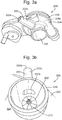
Figures 3a and 3b , thecrankcase ventilation spigot 222 may be formed integrally with theturbocharger compressor housing 220. The turbocharger compressor housing comprises acompressor housing portion 224, configured to house at least a portion of the turbocharger compressor, e.g. therotor 210 of the turbocharger compressor, and a compressorinlet duct portion 226 for carrying intake gases from theintake duct 132 to theinlet 202 of the turbocharger compressor. - The
crankcase ventilation spigot 222 may be formed integrally with thecompressor housing portion 224 and/or the compressorinlet duct portion 226. As depicted, thecompressor housing portion 224, the compressorinlet duct portion 226 and thecrankcase ventilation spigot 222 may be formed integrally with one another such that theturbocharger compressor housing 220 is a one-piece component. For example, theturbocharger compressor housing 220 may be a one-piece cast component. - The
crankcase ventilation spigot 222 may be formed from the same material as thecompressor housing portion 224 and/or the compressorinlet duct portion 226. In particular, thecrankcase ventilation spigot 222 may be manufactured from a metal material. Accordingly, heat may be transferred from thecompressor housing portion 224 to thecrankcase ventilation spigot 222 through heat conduction more effectively than if thecrankcase ventilation spigot 222 was manufactured from a different material. - The
compressor housing portion 224 may at least partially define an outlet flow passage of the turbocharger compressor. For example, thecompressor housing portion 224 may at least partially define anoutlet volume 224a, e.g. a diffuser, volute or scroll of the turbocharger compressor. Gases within the outlet volume may have been heated by virtue of the action of the turbocharger compressor. Thecompressor housing portion 224 may be heated by the gases within theoutlet volume 224a. - Referring for
Figures 3a and 3b , thecrankcase ventilation spigot 222 comprises aninlet opening 222a, for receiving the crankcase ventilation gases from thecrankcase ventilation duct 124, anoutlet opening 222b, though which the crankcase ventilation gases enter the compressorinlet duct portion 226 orcompressor housing portion 224, and aduct portion 222c extending between the inlet andoutlet openings - As shown in
Figure 3a , thecrankcase ventilation spigot 222 may be arranged such that a wall of theduct portion 222c is in contact with or is integrally formed with thecompressor housing portion 224. In particular, the wall of theduct portion 222c may be in contact with or integrally formed with a part of thecompressor housing portion 224 forming a wall of thecompressor outlet volume 224a. For example, theduct portion 222c may be in contact, e.g. in direct contact, with or connected, e.g. directly connected, to thecompressor housing portion 224, e.g. a wall of the compressor housing portion, at a position on theduct portion 222c between the inlet opening and theinlet opening 222a and theoutlet opening 222b. In one or more arrangements, theduct portion 222c may be in contact, e.g. in direct contact, with or connected, e.g. directly connected, to the compressor housing portion, e.g. a wall of the compressor housing portion, over a length of theduct portion 222c extending from or proximate to the outlet opening 222b towards theinlet opening 222a - With reference to
Figure 3b , thecrankcase ventilation spigot 222 may be arranged such that theoutlet opening 222b is adjacent, e.g. immediately adjacent, to theinlet 202 of the turbocharger compressor. - With reference to
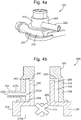
Figures 4a and 4b , in another arrangement of the present disclosure theturbocharger compressor assembly 200 may comprise a crankcaseventilation inlet chamber 230. Thecrankcase ventilation spigot 222 is in fluidic communication with the crankcaseventilation inlet chamber 230 and the crankcase ventilation gases are introduced into the crankcaseventilation inlet chamber 230 before flowing from the crankcaseventilation inlet chamber 230 into the compressorinlet duct portion 226 orcompressor housing portion 224, e.g. via apassage 240 formed between the crankcaseventilation inlet chamber 230 and the compressorinlet duct portion 226 orcompressor housing portion 224. - As shown, the crankcase
ventilation inlet chamber 230 is arranged about theturbocharger compressor inlet 202. The crankcaseventilation inlet chamber 230 may be arranged about the compressorinlet duct portion 226. For example, the crankcase ventilation inlet chamber 30 may comprise a toroidal volume defined about an axis that is substantially aligned with a central axis of the turbocharger compressorinlet duct portion 226, e.g. the direction of the flow of inlet gases into the turbocharger compressor. - At least a portion of a wall forming the crankcase
ventilation inlet chamber 230 may be formed by, or integrally formed with, the compressorinlet duct portion 226 and/or thecompressor housing portion 224. For example, as shown inFigure 4b , an inner, e.g. radially inner,wall 232 of the crankcaseventilation inlet chamber 230 may be formed by the compressorinlet duct portion 226. Additionally or alternatively, afirst end wall 234, e.g. at a first axial end of the crankcaseventilation inlet chamber 230, may be formed by thecompressor housing portion 224. - As described above, the
compressor housing portion 224 may be heated by the gases within theoutlet volume 224a of the compressor. The crankcase ventilation gases within the crankcaseventilation inlet chamber 230, which are in contact with thefirst end wall 234, may therefore be heated. - Additionally, the compressor
inlet duct portion 226 is in thermal communication with thecompressor housing portion 224 and is heated by the gases within thecompressor outlet volume 224a through thermal conduction, e.g. via the material of thecompressor housing portion 224. Accordingly, the crankcase ventilation gases within the crankcaseventilation inlet chamber 230, which are in contact with theinner wall 232, may be heated. - As shown in
Figure 4b , the outlet opening 222b of thecrankcase ventilation spigot 222 may be positioned at a first end, e.g. axial end, of the crankcaseventilation inlet chamber 230, e.g. adjacent to thefirst end wall 234. Anopening 242 of thepassage 240 into the crankcaseventilation inlet chamber 230 may be spaced apart from outlet opening 222b along a length of a wall of the crankcaseventilation inlet chamber 230 formed by the compressorinlet duct portion 226 and/or thecompressor housing portion 224. For example, theopening 242 may be formed adjacent to asecond end wall 236 of theinlet chamber 230, e.g. at a second (axial) end of the crankcaseventilation inlet chamber 230. The crankcase ventilation gases may therefore flow over the length of wall before flowing through thepassage 240 into the compressorinlet duct portion 226 or thecompressor housing portion 224. - As shown in
Figures 4a and 4b , the turbocharger assembly may comprise achamber forming part 300. Thechamber forming part 300 may be coupled to thecompressor housing 220. Thechamber forming part 300 may comprise a hollow substantiallycylindrical portion 310 positioned about theintake duct portion 226 of thecompressor housing 220 when thechamber forming part 300 is coupled to thecompressor housing 220. An outer, e.g. radially outer,wall 238 of theinlet chamber 230 may be formed by thechamber forming part 300, e.g. by the hollowcylindrical portion 310. - The
crankcase ventilation spigot 222 may be coupled to or formed integrally with thechamber forming part 300. Theoutlet opening 222b of the crankcase ventilation spigot may be formed in thecylindrical portion 310 of the chamber forming part, e.g. in theouter wall 238 of the crankcaseventilation inlet chamber 230. - In the arrangement shown in
Figures 4a and 4b , thechamber forming part 300 is configured to form thesecond end wall 236 of the crankcaseventilation inlet chamber 230. However in other arrangements, thesecond end wall 236 may be formed by theintake duct 132, as described below. - With reference to
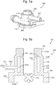
Figures 5a and 5b , in other arrangements of the disclosure, theturbocharger compressor housing 220, e.g. thecompressor housing portion 224, may comprise awall portion 225 extending about the compressorinlet duct portion 226 and spaced apart, e.g. radially apart, from the compressorinlet duct portion 226. At least part of the crankcaseventilation inlet chamber 230 is formed between thewall portion 225 and the compressorinlet duct portion 226. Thewall portion 225 of the compressor housing therefore forms at least part of theouter wall 238 of theinlet chamber 230. - As depicted, when the
compressor housing 220 comprises thewall portion 225, thecrankcase ventilation spigot 222 may be coupled to or integrally formed with thewall portion 225. Theoutlet opening 222b of thespigot 222 may be formed through thewall portion 225 into the crankcaseventilation inlet chamber 230. Thespigot 222 may thereby be formed integrally with thecompressor housing portion 224, and optionally the compressorinlet duct portion 226. - In the arrangement shown in
Figure 5b , theintake duct 132 comprises achamber forming portion 133. Thechamber forming portion 133 comprises a hollow, substantially cylindrical portion that extends about the compressorinlet duct portion 226 of theturbocharger compressor housing 220 when theintake duct 132 is coupled to the compressorinlet duct portion 226. - As depicted in
Figure 5b , thechamber forming portion 133 of theintake duct 132 may form part of theouter wall 238 of the crankcaseventilation inlet chamber 230. Thechamber forming portion 133 and thewall portion 225 of thecompressor housing 220 may together form theouter wall 238 of theinlet chamber 230. Additionally, thechamber forming portion 133 of theintake duct 132 may at least partially form thesecond end wall 236 of theinlet chamber 230. - In other arrangements, the
wall portion 225 may form, e.g. entirely form, theouter wall 238 and thechamber forming portion 133 of theintake duct 132 may form thesecond end wall 236 of the inlet chamber. Alternatively, thewall portion 225 may form, e.g. entirely form, theouter wall 238 and thesecond end wall 236 of theinlet chamber 230. - The
chamber forming portion 133 may be formed integrally with theintake duct 132. In some arrangements, theintake duct 132 may comprise aduct portion 132a and aconnection portion 132b for connecting the duct portion to the compressorinlet duct portion 226. Theconnection portion 132b may be coupled to or formed integrally with theduct portion 132a. Thechamber forming portion 133 may be formed by theconnection portion 132b. - Although in the arrangements shown in
Figures 4b and5b , thespigot 222 is spaced apart from thecompressor housing portion 224, e.g. the part of the compressor housing portion forming theoutlet volume 224a of theturbocharger compressor assembly 200, in other arrangements, a wall of theduct portion 222c of thespigot 222 may be in contact with or may be integrally formed with thecompressor housing portion 224. In either arrangement, thespigot 222 may be formed from the same material as thecompressor housing portion 224 and compressorinlet duct portion 226, e.g. from a metal material. - In either of the arrangements shown in
Figures 4a and 4b , andFigures 5a and 5b , the crankcaseventilation inlet chamber 230 may be tuned to act as an intake resonator for damping vibrations of inlet gases within theintake duct 132 at the desired frequency. In particular, the size of the crankcaseventilation inlet chamber 230 and/or the size of thepassage 240 may be selected in order to damp vibrations of the inlet gases at the desired frequency. Theintake resonator 136 shown inFigure 2 may therefore be omitted in arrangements of theengine assembly 100 comprising thecompressor assembly 200 shown inFigures 4a and 4b or5a and 5b . - The following additional, numbered statements of invention are also included within the specification and form part of the present disclosure:
- Statement 1. A turbocharger compressor housing for a motor vehicle, the housing comprising:
- a compressor housing portion for housing at least a portion of the turbocharger compressor;
- a compressor inlet duct portion for carrying a flow of inlet gases to an inlet of the turbocharger compressor; and
- a crankcase ventilation pipe in fluidic communication with the inlet of the turbocharger compressor, the pipe for the introduction of crankcase ventilation gases into the turbocharger compressor, wherein the pipe is integrally formed with the compressor housing portion.
-
Statement 2. The turbocharger compressor housing of statement 1, wherein the turbocharger compressor housing is a one-piece metal component. - Statement 3. The turbocharger compressor housing of
statement 1 or 2, wherein the crankcase ventilation pipe comprises an inlet opening, an outlet opening and a duct portion extending between the inlet opening and the outlet opening, wherein the duct portion is in contact with, or is integrally formed with the compressor housing portion. -
Statement 4. The turbocharger compressor housing of any of the preceding statements, wherein the compressor housing portion at least partially defines an outlet flow passage of the turbocharger compressor. - Statement 5. The turbocharger compressor housing of any of the preceding statements, wherein the turbocharger compressor housing further comprises:
a crankcase ventilation inlet chamber extending about the compressor intake duct, wherein the crankcase ventilation inlet chamber is in fluidic communication with the inlet of the turbocharger compressor, and wherein the pipe is in fluidic communication with the crankcase ventilation inlet chamber. - Statement 6. The turbocharger compressor housing according to statement 5, wherein at least a portion of a wall of the crankcase ventilation inlet chamber is formed by the compressor intake duct and/or the compressor housing portion.
- Statement 7. The turbocharger compressor housing of statement 6, wherein a passage is formed between the crankcase ventilation inlet chamber and the compressor intake duct or the compressor housing portion, wherein an opening of the passage into the crankcase ventilation inlet chamber is spaced apart from an opening of the pipe into the crankcase ventilation inlet chamber along a wall of the of the crankcase ventilation inlet chamber formed by the compressor intake duct and/or the compressor housing portion.
- Statement 8. The turbocharger compressor housing according to any of statements 5 to 7, wherein the turbocharger compressor housing further comprises a wall portion extending at least partially about the compressor inlet duct portion, wherein an outer wall of the crankcase ventilation inlet chamber is at least partially formed by the wall portion.
- Statement 9. The turbocharger compressor housing according to statement 8, wherein the wall portion is integrally formed with the compressor housing portion.
-
Statement 10. The turbocharger compressor housing according to any of statements 5 to 9, wherein the crankcase ventilation inlet chamber is configured to damp pressure variation in the inlet air arriving at the compressor inlet duct portion. - Statement 11. An intake assembly comprising, the turbocharger compressor housing according to any of the preceding statements and an intake duct in fluidic communication with the compressor inlet duct portion.
-
Statement 12. The intake assembly of statement 11 when depending on any of statements 5 to 10, wherein a wall of the crankcase ventilation inlet chamber is at least partially formed by the intake duct. -
Statement 13. The intake assembly ofstatement 12, wherein an axial end wall of the crankcase ventilation inlet chamber is at least partially formed by the intake duct. -
Statement 14. The intake assembly ofstatement - Statement 15. A motor vehicle comprising the turbocharger compressor housing of any of statements 1 to 10 or the intake assembly of any of statements 11 to 14.
- It will be appreciated by those skilled in the art that although the invention has been described by way of example, with reference to one or more exemplary examples, it is not limited to the disclosed examples and that alternative examples could be constructed without departing from the scope of the invention as defined by the appended claims.
Claims (15)
- A turbocharger compressor housing for a motor vehicle, the housing comprising:a compressor housing portion for housing at least a portion of the turbocharger compressor;a compressor inlet duct portion for carrying a flow of inlet gases to an inlet of the turbocharger compressor; anda crankcase ventilation pipe in fluidic communication with the inlet of the turbocharger compressor, the pipe for the introduction of crankcase ventilation gases into the turbocharger compressor, wherein the pipe is integrally formed with the compressor housing portion.
- The turbocharger compressor housing of claim 1, wherein the turbocharger compressor housing is a one-piece metal component.
- The turbocharger compressor housing of claim 1 or 2, wherein the crankcase ventilation pipe comprises an inlet opening, an outlet opening and a duct portion extending between the inlet opening and the outlet opening, wherein the duct portion is in contact with, or is integrally formed with the compressor housing portion.
- The turbocharger compressor housing of any of the preceding claims, wherein the compressor housing portion at least partially defines an outlet flow passage of the turbocharger compressor.
- The turbocharger compressor housing of any of the preceding claims, wherein the turbocharger compressor housing further comprises:
a crankcase ventilation inlet chamber extending about the compressor intake duct, wherein the crankcase ventilation inlet chamber is in fluidic communication with the inlet of the turbocharger compressor, and wherein the pipe is in fluidic communication with the crankcase ventilation inlet chamber. - The turbocharger compressor housing according to claim 5, wherein at least a portion of a wall of the crankcase ventilation inlet chamber is formed by the compressor intake duct and/or the compressor housing portion.
- The turbocharger compressor housing of claim 6, wherein a passage is formed between the crankcase ventilation inlet chamber and the compressor intake duct or the compressor housing portion, wherein an opening of the passage into the crankcase ventilation inlet chamber is spaced apart from an opening of the pipe into the crankcase ventilation inlet chamber along a wall of the of the crankcase ventilation inlet chamber formed by the compressor intake duct and/or the compressor housing portion.
- The turbocharger compressor housing according to any of claims 5 to 7, wherein the turbocharger compressor housing further comprises a wall portion extending at least partially about the compressor inlet duct portion, wherein an outer wall of the crankcase ventilation inlet chamber is at least partially formed by the wall portion.
- The turbocharger compressor housing according to claim 8, wherein the wall portion is integrally formed with the compressor housing portion.
- The turbocharger compressor housing according to any of claims 5 to 9, wherein the crankcase ventilation inlet chamber is configured to damp pressure variation in the inlet air arriving at the compressor inlet duct portion.
- An intake assembly comprising, the turbocharger compressor housing according to any of the preceding claims and an intake duct in fluidic communication with the compressor inlet duct portion.
- The intake assembly of claim 11 when depending on any of claims 5 to 10, wherein a wall of the crankcase ventilation inlet chamber is at least partially formed by the intake duct.
- The intake assembly of claim 12, wherein an axial end wall of the crankcase ventilation inlet chamber is at least partially formed by the intake duct.
- The intake assembly of claim 12 or 13, wherein at least a portion of an outer wall of the crankcase ventilation inlet chamber is formed by the intake duct.
- A motor vehicle comprising the turbocharger compressor housing of any of claims 1 to 10 or the intake assembly of any of claims 11 to 14.
Applications Claiming Priority (1)
| Application Number | Priority Date | Filing Date | Title |
|---|---|---|---|
| GB1903892.6A GB2582360B (en) | 2019-03-21 | 2019-03-21 | Turbocharger compressor housings |
Publications (2)
| Publication Number | Publication Date |
|---|---|
| EP3712440A1 true EP3712440A1 (en) | 2020-09-23 |
| EP3712440B1 EP3712440B1 (en) | 2024-06-19 |
Family
ID=66381454
Family Applications (1)
| Application Number | Title | Priority Date | Filing Date |
|---|---|---|---|
| EP20159325.8A Active EP3712440B1 (en) | 2019-03-21 | 2020-02-25 | Turbocharger compressor housing |
Country Status (4)
| Country | Link |
|---|---|
| US (1) | US20200300123A1 (en) |
| EP (1) | EP3712440B1 (en) |
| CN (1) | CN111720361A (en) |
| GB (1) | GB2582360B (en) |
Cited By (1)
| Publication number | Priority date | Publication date | Assignee | Title |
|---|---|---|---|---|
| CN115773166A (en) * | 2022-11-29 | 2023-03-10 | 重庆长安汽车股份有限公司 | Structure and method for preventing crankcase ventilation pipeline from being frozen |
Families Citing this family (2)
| Publication number | Priority date | Publication date | Assignee | Title |
|---|---|---|---|---|
| EP3708821A1 (en) * | 2019-03-15 | 2020-09-16 | Borgwarner Inc. | Compressor for charging a combustion engine |
| CN114033588B (en) * | 2021-11-02 | 2023-02-28 | 潍坊科技学院 | Compressor integrated heat exchange device of supercharger for respirator closed cycle engine |
Citations (3)
| Publication number | Priority date | Publication date | Assignee | Title |
|---|---|---|---|---|
| DE4213047A1 (en) * | 1992-04-21 | 1993-10-28 | Kuehnle Kopp Kausch Ag | Radial compressor for vehicle exhaust gas turbocharger - uses feed pipe to deliver flow medium to influence conditions in circulation chamber |
| EP2570629A1 (en) * | 2010-12-28 | 2013-03-20 | Mitsubishi Heavy Industries, Ltd. | Housing structure for exhaust turbocharger |
| US20170342880A1 (en) * | 2016-05-31 | 2017-11-30 | Electro-Motive Diesel, Inc. | Crankcase ventilation system for an internal combustion engine |
Family Cites Families (8)
| Publication number | Priority date | Publication date | Assignee | Title |
|---|---|---|---|---|
| US7204241B2 (en) * | 2004-08-30 | 2007-04-17 | Honeywell International, Inc. | Compressor stage separation system |
| US7698894B2 (en) * | 2006-05-22 | 2010-04-20 | International Engine Intellectual Property Company, Llc | Engine intake air compressor and method |
| GB0724701D0 (en) * | 2007-12-18 | 2008-01-30 | Cummins Turbo Tech Ltd | Compressor |
| JP5319461B2 (en) * | 2009-08-28 | 2013-10-16 | ダイハツ工業株式会社 | Blow-by gas processing device in an internal combustion engine with an exhaust turbocharger |
| NL1040722B1 (en) * | 2014-03-12 | 2015-11-19 | Mitsubishi Turbocharger And Engine Europe B V | Compressor housing. |
| JP6308875B2 (en) * | 2014-06-02 | 2018-04-11 | 日野自動車株式会社 | Oil separator structure |
| JP6336878B2 (en) * | 2014-10-07 | 2018-06-06 | 日野自動車株式会社 | Oil separator structure |
| JP6378726B2 (en) * | 2016-09-26 | 2018-08-22 | 株式会社Subaru | Evaporative fuel introduction device |
-
2019
- 2019-03-21 GB GB1903892.6A patent/GB2582360B/en not_active Expired - Fee Related
-
2020
- 2020-02-20 CN CN202010104087.2A patent/CN111720361A/en active Pending
- 2020-02-25 EP EP20159325.8A patent/EP3712440B1/en active Active
- 2020-03-18 US US16/823,204 patent/US20200300123A1/en not_active Abandoned
Patent Citations (3)
| Publication number | Priority date | Publication date | Assignee | Title |
|---|---|---|---|---|
| DE4213047A1 (en) * | 1992-04-21 | 1993-10-28 | Kuehnle Kopp Kausch Ag | Radial compressor for vehicle exhaust gas turbocharger - uses feed pipe to deliver flow medium to influence conditions in circulation chamber |
| EP2570629A1 (en) * | 2010-12-28 | 2013-03-20 | Mitsubishi Heavy Industries, Ltd. | Housing structure for exhaust turbocharger |
| US20170342880A1 (en) * | 2016-05-31 | 2017-11-30 | Electro-Motive Diesel, Inc. | Crankcase ventilation system for an internal combustion engine |
Cited By (2)
| Publication number | Priority date | Publication date | Assignee | Title |
|---|---|---|---|---|
| CN115773166A (en) * | 2022-11-29 | 2023-03-10 | 重庆长安汽车股份有限公司 | Structure and method for preventing crankcase ventilation pipeline from being frozen |
| CN115773166B (en) * | 2022-11-29 | 2024-04-12 | 重庆长安汽车股份有限公司 | Structure and method for preventing crankcase ventilation pipeline from icing |
Also Published As
| Publication number | Publication date |
|---|---|
| GB201903892D0 (en) | 2019-05-08 |
| EP3712440B1 (en) | 2024-06-19 |
| GB2582360A (en) | 2020-09-23 |
| CN111720361A (en) | 2020-09-29 |
| US20200300123A1 (en) | 2020-09-24 |
| GB2582360B (en) | 2021-03-24 |
Similar Documents
| Publication | Publication Date | Title |
|---|---|---|
| RU2478801C2 (en) | Sealing of hub cavity of outlet casing in gas turbine engine | |
| US4922882A (en) | Crankcase ventilation system | |
| EP3712440A1 (en) | Turbocharger compressor housing | |
| EP1785613B1 (en) | Exhaust turbo-supercharger | |
| US8177024B2 (en) | Accoustic attenuation device for an intake line of a combustion engine and intake line incorporating same | |
| JP6220803B2 (en) | Turbocharger | |
| CN102071987B (en) | Crankcase vent nozzle for internal combustion engine | |
| RU2007127559A (en) | TURBO MACHINE CONTAINING A CENTRIFUGAL COMPRESSOR VALVE LOWER COOLING SYSTEM | |
| US20150107935A1 (en) | Intake system having a silencer device | |
| US20080141680A1 (en) | System for ventilating a combustion chamber wall | |
| CN108625908A (en) | Turbocharger | |
| EP3361084B1 (en) | Acoustic damper with resonator members arranged in-parallel | |
| KR20180099524A (en) | Turbocharger | |
| CN111305980B (en) | Exhaust gas recirculation compressor inlet thermal isolation system | |
| CN115126556B (en) | Turbine structure and air cycle machine applying same | |
| US20180291764A1 (en) | Turbocharger | |
| CN113906209A (en) | Cylinder head with integrated turbocharger | |
| US20190010903A1 (en) | Acoustic attenuation device for an intake line | |
| CN110573749B (en) | Compressor housing and turbocharger provided with same | |
| EP3530953A1 (en) | Compressor section of a turbocharger with a cooled compressor housing | |
| CN110578713B (en) | Volute structure and centrifugal compressor | |
| CN107567536B (en) | Closing sleeve for turbine bearing and turbine equipped with said sleeve | |
| JP2002070676A (en) | Control unit accommodation structure | |
| KR20180099509A (en) | Turbocharger | |
| KR20180109136A (en) | Structure of Engine Mount |
Legal Events
| Date | Code | Title | Description |
|---|---|---|---|
| PUAI | Public reference made under article 153(3) epc to a published international application that has entered the european phase |
Free format text: ORIGINAL CODE: 0009012 |
|
| STAA | Information on the status of an ep patent application or granted ep patent |
Free format text: STATUS: THE APPLICATION HAS BEEN PUBLISHED |
|
| AK | Designated contracting states |
Kind code of ref document: A1 Designated state(s): AL AT BE BG CH CY CZ DE DK EE ES FI FR GB GR HR HU IE IS IT LI LT LU LV MC MK MT NL NO PL PT RO RS SE SI SK SM TR |
|
| AX | Request for extension of the european patent |
Extension state: BA ME |
|
| STAA | Information on the status of an ep patent application or granted ep patent |
Free format text: STATUS: REQUEST FOR EXAMINATION WAS MADE |
|
| 17P | Request for examination filed |
Effective date: 20210222 |
|
| RBV | Designated contracting states (corrected) |
Designated state(s): AL AT BE BG CH CY CZ DE DK EE ES FI FR GB GR HR HU IE IS IT LI LT LU LV MC MK MT NL NO PL PT RO RS SE SI SK SM TR |
|
| STAA | Information on the status of an ep patent application or granted ep patent |
Free format text: STATUS: EXAMINATION IS IN PROGRESS |
|
| 17Q | First examination report despatched |
Effective date: 20220707 |
|
| P01 | Opt-out of the competence of the unified patent court (upc) registered |
Effective date: 20230620 |
|
| GRAP | Despatch of communication of intention to grant a patent |
Free format text: ORIGINAL CODE: EPIDOSNIGR1 |
|
| STAA | Information on the status of an ep patent application or granted ep patent |
Free format text: STATUS: GRANT OF PATENT IS INTENDED |
|
| INTG | Intention to grant announced |
Effective date: 20240131 |
|
| GRAS | Grant fee paid |
Free format text: ORIGINAL CODE: EPIDOSNIGR3 |
|
| GRAA | (expected) grant |
Free format text: ORIGINAL CODE: 0009210 |
|
| STAA | Information on the status of an ep patent application or granted ep patent |
Free format text: STATUS: THE PATENT HAS BEEN GRANTED |
|
| REG | Reference to a national code |
Ref country code: DE Ref legal event code: R084 Ref document number: 602020032522 Country of ref document: DE |
|
| AK | Designated contracting states |
Kind code of ref document: B1 Designated state(s): AL AT BE BG CH CY CZ DE DK EE ES FI FR GB GR HR HU IE IS IT LI LT LU LV MC MK MT NL NO PL PT RO RS SE SI SK SM TR |
|
| REG | Reference to a national code |
Ref country code: GB Ref legal event code: FG4D |
|
| REG | Reference to a national code |
Ref country code: CH Ref legal event code: EP |
|
| REG | Reference to a national code |
Ref country code: DE Ref legal event code: R096 Ref document number: 602020032522 Country of ref document: DE |
|
| PG25 | Lapsed in a contracting state [announced via postgrant information from national office to epo] |
Ref country code: BG Free format text: LAPSE BECAUSE OF FAILURE TO SUBMIT A TRANSLATION OF THE DESCRIPTION OR TO PAY THE FEE WITHIN THE PRESCRIBED TIME-LIMIT Effective date: 20240619 |
|
| PG25 | Lapsed in a contracting state [announced via postgrant information from national office to epo] |
Ref country code: FI Free format text: LAPSE BECAUSE OF FAILURE TO SUBMIT A TRANSLATION OF THE DESCRIPTION OR TO PAY THE FEE WITHIN THE PRESCRIBED TIME-LIMIT Effective date: 20240619 Ref country code: HR Free format text: LAPSE BECAUSE OF FAILURE TO SUBMIT A TRANSLATION OF THE DESCRIPTION OR TO PAY THE FEE WITHIN THE PRESCRIBED TIME-LIMIT Effective date: 20240619 |
|
| REG | Reference to a national code |
Ref country code: LT Ref legal event code: MG9D |
|
| PG25 | Lapsed in a contracting state [announced via postgrant information from national office to epo] |
Ref country code: GR Free format text: LAPSE BECAUSE OF FAILURE TO SUBMIT A TRANSLATION OF THE DESCRIPTION OR TO PAY THE FEE WITHIN THE PRESCRIBED TIME-LIMIT Effective date: 20240920 |
|
| REG | Reference to a national code |
Ref country code: NL Ref legal event code: MP Effective date: 20240619 |
|
| PG25 | Lapsed in a contracting state [announced via postgrant information from national office to epo] |
Ref country code: LV Free format text: LAPSE BECAUSE OF FAILURE TO SUBMIT A TRANSLATION OF THE DESCRIPTION OR TO PAY THE FEE WITHIN THE PRESCRIBED TIME-LIMIT Effective date: 20240619 |
|
| PG25 | Lapsed in a contracting state [announced via postgrant information from national office to epo] |
Ref country code: NO Free format text: LAPSE BECAUSE OF FAILURE TO SUBMIT A TRANSLATION OF THE DESCRIPTION OR TO PAY THE FEE WITHIN THE PRESCRIBED TIME-LIMIT Effective date: 20240919 Ref country code: LV Free format text: LAPSE BECAUSE OF FAILURE TO SUBMIT A TRANSLATION OF THE DESCRIPTION OR TO PAY THE FEE WITHIN THE PRESCRIBED TIME-LIMIT Effective date: 20240619 Ref country code: HR Free format text: LAPSE BECAUSE OF FAILURE TO SUBMIT A TRANSLATION OF THE DESCRIPTION OR TO PAY THE FEE WITHIN THE PRESCRIBED TIME-LIMIT Effective date: 20240619 Ref country code: GR Free format text: LAPSE BECAUSE OF FAILURE TO SUBMIT A TRANSLATION OF THE DESCRIPTION OR TO PAY THE FEE WITHIN THE PRESCRIBED TIME-LIMIT Effective date: 20240920 Ref country code: FI Free format text: LAPSE BECAUSE OF FAILURE TO SUBMIT A TRANSLATION OF THE DESCRIPTION OR TO PAY THE FEE WITHIN THE PRESCRIBED TIME-LIMIT Effective date: 20240619 Ref country code: BG Free format text: LAPSE BECAUSE OF FAILURE TO SUBMIT A TRANSLATION OF THE DESCRIPTION OR TO PAY THE FEE WITHIN THE PRESCRIBED TIME-LIMIT Effective date: 20240619 Ref country code: RS Free format text: LAPSE BECAUSE OF FAILURE TO SUBMIT A TRANSLATION OF THE DESCRIPTION OR TO PAY THE FEE WITHIN THE PRESCRIBED TIME-LIMIT Effective date: 20240919 |
|
| PG25 | Lapsed in a contracting state [announced via postgrant information from national office to epo] |
Ref country code: NL Free format text: LAPSE BECAUSE OF FAILURE TO SUBMIT A TRANSLATION OF THE DESCRIPTION OR TO PAY THE FEE WITHIN THE PRESCRIBED TIME-LIMIT Effective date: 20240619 |
|
| REG | Reference to a national code |
Ref country code: AT Ref legal event code: MK05 Ref document number: 1696076 Country of ref document: AT Kind code of ref document: T Effective date: 20240619 |
|
| PG25 | Lapsed in a contracting state [announced via postgrant information from national office to epo] |
Ref country code: NL Free format text: LAPSE BECAUSE OF FAILURE TO SUBMIT A TRANSLATION OF THE DESCRIPTION OR TO PAY THE FEE WITHIN THE PRESCRIBED TIME-LIMIT Effective date: 20240619 |
|
| PG25 | Lapsed in a contracting state [announced via postgrant information from national office to epo] |
Ref country code: PT Free format text: LAPSE BECAUSE OF FAILURE TO SUBMIT A TRANSLATION OF THE DESCRIPTION OR TO PAY THE FEE WITHIN THE PRESCRIBED TIME-LIMIT Effective date: 20241021 |
|
| PG25 | Lapsed in a contracting state [announced via postgrant information from national office to epo] |
Ref country code: PT Free format text: LAPSE BECAUSE OF FAILURE TO SUBMIT A TRANSLATION OF THE DESCRIPTION OR TO PAY THE FEE WITHIN THE PRESCRIBED TIME-LIMIT Effective date: 20241021 |
|
| PG25 | Lapsed in a contracting state [announced via postgrant information from national office to epo] |
Ref country code: PL Free format text: LAPSE BECAUSE OF FAILURE TO SUBMIT A TRANSLATION OF THE DESCRIPTION OR TO PAY THE FEE WITHIN THE PRESCRIBED TIME-LIMIT Effective date: 20240619 |
|
| PG25 | Lapsed in a contracting state [announced via postgrant information from national office to epo] |
Ref country code: EE Free format text: LAPSE BECAUSE OF FAILURE TO SUBMIT A TRANSLATION OF THE DESCRIPTION OR TO PAY THE FEE WITHIN THE PRESCRIBED TIME-LIMIT Effective date: 20240619 |
|
| PG25 | Lapsed in a contracting state [announced via postgrant information from national office to epo] |
Ref country code: IS Free format text: LAPSE BECAUSE OF FAILURE TO SUBMIT A TRANSLATION OF THE DESCRIPTION OR TO PAY THE FEE WITHIN THE PRESCRIBED TIME-LIMIT Effective date: 20241019 Ref country code: AT Free format text: LAPSE BECAUSE OF FAILURE TO SUBMIT A TRANSLATION OF THE DESCRIPTION OR TO PAY THE FEE WITHIN THE PRESCRIBED TIME-LIMIT Effective date: 20240619 |
|
| PG25 | Lapsed in a contracting state [announced via postgrant information from national office to epo] |
Ref country code: CZ Free format text: LAPSE BECAUSE OF FAILURE TO SUBMIT A TRANSLATION OF THE DESCRIPTION OR TO PAY THE FEE WITHIN THE PRESCRIBED TIME-LIMIT Effective date: 20240619 |
|
| PG25 | Lapsed in a contracting state [announced via postgrant information from national office to epo] |
Ref country code: RO Free format text: LAPSE BECAUSE OF FAILURE TO SUBMIT A TRANSLATION OF THE DESCRIPTION OR TO PAY THE FEE WITHIN THE PRESCRIBED TIME-LIMIT Effective date: 20240619 Ref country code: SK Free format text: LAPSE BECAUSE OF FAILURE TO SUBMIT A TRANSLATION OF THE DESCRIPTION OR TO PAY THE FEE WITHIN THE PRESCRIBED TIME-LIMIT Effective date: 20240619 |
|
| PG25 | Lapsed in a contracting state [announced via postgrant information from national office to epo] |
Ref country code: SM Free format text: LAPSE BECAUSE OF FAILURE TO SUBMIT A TRANSLATION OF THE DESCRIPTION OR TO PAY THE FEE WITHIN THE PRESCRIBED TIME-LIMIT Effective date: 20240619 Ref country code: ES Free format text: LAPSE BECAUSE OF FAILURE TO SUBMIT A TRANSLATION OF THE DESCRIPTION OR TO PAY THE FEE WITHIN THE PRESCRIBED TIME-LIMIT Effective date: 20240619 |
|
| PG25 | Lapsed in a contracting state [announced via postgrant information from national office to epo] |
Ref country code: SM Free format text: LAPSE BECAUSE OF FAILURE TO SUBMIT A TRANSLATION OF THE DESCRIPTION OR TO PAY THE FEE WITHIN THE PRESCRIBED TIME-LIMIT Effective date: 20240619 Ref country code: SK Free format text: LAPSE BECAUSE OF FAILURE TO SUBMIT A TRANSLATION OF THE DESCRIPTION OR TO PAY THE FEE WITHIN THE PRESCRIBED TIME-LIMIT Effective date: 20240619 Ref country code: RO Free format text: LAPSE BECAUSE OF FAILURE TO SUBMIT A TRANSLATION OF THE DESCRIPTION OR TO PAY THE FEE WITHIN THE PRESCRIBED TIME-LIMIT Effective date: 20240619 Ref country code: PL Free format text: LAPSE BECAUSE OF FAILURE TO SUBMIT A TRANSLATION OF THE DESCRIPTION OR TO PAY THE FEE WITHIN THE PRESCRIBED TIME-LIMIT Effective date: 20240619 Ref country code: IS Free format text: LAPSE BECAUSE OF FAILURE TO SUBMIT A TRANSLATION OF THE DESCRIPTION OR TO PAY THE FEE WITHIN THE PRESCRIBED TIME-LIMIT Effective date: 20241019 Ref country code: ES Free format text: LAPSE BECAUSE OF FAILURE TO SUBMIT A TRANSLATION OF THE DESCRIPTION OR TO PAY THE FEE WITHIN THE PRESCRIBED TIME-LIMIT Effective date: 20240619 Ref country code: EE Free format text: LAPSE BECAUSE OF FAILURE TO SUBMIT A TRANSLATION OF THE DESCRIPTION OR TO PAY THE FEE WITHIN THE PRESCRIBED TIME-LIMIT Effective date: 20240619 Ref country code: CZ Free format text: LAPSE BECAUSE OF FAILURE TO SUBMIT A TRANSLATION OF THE DESCRIPTION OR TO PAY THE FEE WITHIN THE PRESCRIBED TIME-LIMIT Effective date: 20240619 Ref country code: AT Free format text: LAPSE BECAUSE OF FAILURE TO SUBMIT A TRANSLATION OF THE DESCRIPTION OR TO PAY THE FEE WITHIN THE PRESCRIBED TIME-LIMIT Effective date: 20240619 |
|
| PG25 | Lapsed in a contracting state [announced via postgrant information from national office to epo] |
Ref country code: IT Free format text: LAPSE BECAUSE OF FAILURE TO SUBMIT A TRANSLATION OF THE DESCRIPTION OR TO PAY THE FEE WITHIN THE PRESCRIBED TIME-LIMIT Effective date: 20240619 |
|
| REG | Reference to a national code |
Ref country code: DE Ref legal event code: R097 Ref document number: 602020032522 Country of ref document: DE |
|
| PG25 | Lapsed in a contracting state [announced via postgrant information from national office to epo] |
Ref country code: DK Free format text: LAPSE BECAUSE OF FAILURE TO SUBMIT A TRANSLATION OF THE DESCRIPTION OR TO PAY THE FEE WITHIN THE PRESCRIBED TIME-LIMIT Effective date: 20240619 |
|
| PLBE | No opposition filed within time limit |
Free format text: ORIGINAL CODE: 0009261 |
|
| STAA | Information on the status of an ep patent application or granted ep patent |
Free format text: STATUS: NO OPPOSITION FILED WITHIN TIME LIMIT |
|
| 26N | No opposition filed |
Effective date: 20250320 |
|
| PG25 | Lapsed in a contracting state [announced via postgrant information from national office to epo] |
Ref country code: SE Free format text: LAPSE BECAUSE OF FAILURE TO SUBMIT A TRANSLATION OF THE DESCRIPTION OR TO PAY THE FEE WITHIN THE PRESCRIBED TIME-LIMIT Effective date: 20240619 |
|
| PG25 | Lapsed in a contracting state [announced via postgrant information from national office to epo] |
Ref country code: MC Free format text: LAPSE BECAUSE OF FAILURE TO SUBMIT A TRANSLATION OF THE DESCRIPTION OR TO PAY THE FEE WITHIN THE PRESCRIBED TIME-LIMIT Effective date: 20240619 |
|
| REG | Reference to a national code |
Ref country code: CH Ref legal event code: PL |
|
| PG25 | Lapsed in a contracting state [announced via postgrant information from national office to epo] |
Ref country code: LU Free format text: LAPSE BECAUSE OF NON-PAYMENT OF DUE FEES Effective date: 20250225 |
|
| PG25 | Lapsed in a contracting state [announced via postgrant information from national office to epo] |
Ref country code: CH Free format text: LAPSE BECAUSE OF NON-PAYMENT OF DUE FEES Effective date: 20250228 |
|
| GBPC | Gb: european patent ceased through non-payment of renewal fee |
Effective date: 20250225 |
|
| REG | Reference to a national code |
Ref country code: BE Ref legal event code: MM Effective date: 20250228 |
|
| PG25 | Lapsed in a contracting state [announced via postgrant information from national office to epo] |
Ref country code: GB Free format text: LAPSE BECAUSE OF NON-PAYMENT OF DUE FEES Effective date: 20250225 |
|
| PG25 | Lapsed in a contracting state [announced via postgrant information from national office to epo] |
Ref country code: FR Free format text: LAPSE BECAUSE OF NON-PAYMENT OF DUE FEES Effective date: 20250228 |
|
| PG25 | Lapsed in a contracting state [announced via postgrant information from national office to epo] |
Ref country code: BE Free format text: LAPSE BECAUSE OF NON-PAYMENT OF DUE FEES Effective date: 20250228 |
|
| PG25 | Lapsed in a contracting state [announced via postgrant information from national office to epo] |
Ref country code: IE Free format text: LAPSE BECAUSE OF NON-PAYMENT OF DUE FEES Effective date: 20250225 |
|
| PGFP | Annual fee paid to national office [announced via postgrant information from national office to epo] |
Ref country code: DE Payment date: 20260115 Year of fee payment: 7 |