EP3712422A1 - Rotor blade for a wind turbine - Google Patents
Rotor blade for a wind turbine Download PDFInfo
- Publication number
- EP3712422A1 EP3712422A1 EP19164164.6A EP19164164A EP3712422A1 EP 3712422 A1 EP3712422 A1 EP 3712422A1 EP 19164164 A EP19164164 A EP 19164164A EP 3712422 A1 EP3712422 A1 EP 3712422A1
- Authority
- EP
- European Patent Office
- Prior art keywords
- rotor blade
- drain
- closing means
- drain hole
- blade according
- Prior art date
- Legal status (The legal status is an assumption and is not a legal conclusion. Google has not performed a legal analysis and makes no representation as to the accuracy of the status listed.)
- Granted
Links
Images

Classifications
-
- F—MECHANICAL ENGINEERING; LIGHTING; HEATING; WEAPONS; BLASTING
- F03—MACHINES OR ENGINES FOR LIQUIDS; WIND, SPRING, OR WEIGHT MOTORS; PRODUCING MECHANICAL POWER OR A REACTIVE PROPULSIVE THRUST, NOT OTHERWISE PROVIDED FOR
- F03D—WIND MOTORS
- F03D1/00—Wind motors with rotation axis substantially parallel to the air flow entering the rotor
- F03D1/06—Rotors
- F03D1/065—Rotors characterised by their construction elements
- F03D1/0675—Rotors characterised by their construction elements of the blades
-
- F—MECHANICAL ENGINEERING; LIGHTING; HEATING; WEAPONS; BLASTING
- F03—MACHINES OR ENGINES FOR LIQUIDS; WIND, SPRING, OR WEIGHT MOTORS; PRODUCING MECHANICAL POWER OR A REACTIVE PROPULSIVE THRUST, NOT OTHERWISE PROVIDED FOR
- F03D—WIND MOTORS
- F03D80/00—Details, components or accessories not provided for in groups F03D1/00 - F03D17/00
-
- F—MECHANICAL ENGINEERING; LIGHTING; HEATING; WEAPONS; BLASTING
- F05—INDEXING SCHEMES RELATING TO ENGINES OR PUMPS IN VARIOUS SUBCLASSES OF CLASSES F01-F04
- F05B—INDEXING SCHEME RELATING TO WIND, SPRING, WEIGHT, INERTIA OR LIKE MOTORS, TO MACHINES OR ENGINES FOR LIQUIDS COVERED BY SUBCLASSES F03B, F03D AND F03G
- F05B2260/00—Function
- F05B2260/60—Fluid transfer
- F05B2260/602—Drainage
Definitions
- the invention relates to a rotor blade for a wind turbine, comprising an at least partially hollow blade body extending from a root to a tip, which blade body is provided with at least one drain hole connecting the hollow inner with the outer surrounding, which drain hole is positioned in an area close to the tip.
- a wind turbine usually comprises several rotor blades attached to a hub. When wind acts on the rotor blades the hub starts to rotate and drives a generator connected to the hub for producing electrical energy.
- a rotor blade usually comprises an at least partially hollow blade body, which extends from a root, which is fixed to the hub, to a tip. Over its length the blade body changes its cross section from a usually circular cross section at the root to an air foil cross section.
- EP 1 607 623 A2 To drain the water it is known, see for example EP 1 607 623 A2 , to provide at least one drain hole in the area of the tip, which connects the hollow inner of the rotor blade body with the outer surrounding. Through this drain hole the water can be drained from the inner to the outer surrounding.
- a drain hole see EP 1 607 623 A2 , has a very small diameter of less than 1 cm, preferably 5 mm.
- the drain hole in the rotor blade disclosed in EP 1 607 623 A2 has the only purpose to drain water.
- a net or the like is provided in the inner of the blade body at a position spaced apart from the drain hole, which net is water permeable but holds back any dirt or material which may clog the drain hole.
- a hand hole is provided which is closed by means of a lid, through which hand hole for maintenance purpose the worker can reach with his hand into the inner of the hollow blade body for cleaning the net.
- a rotor blade as depicted above is characterised in that the drain hole is closed with a removable plug-like closing means having at least one drain bore.
- the invention proposes to provide a drain hole into which a removable plug-like closing means is inserted.
- This closing means has at least one drain bore, which is permanently open and which connects the inner of the blade body to the outer surrounding allowing to drain any accumulated water. So this plug-like closing means permanently allows for draining water, while on the other hand it is possible to provide a way larger drain hole in the blade body, which drain hole preferably has a diameter of at least 10 mm, preferably of at least 20 mm and especially of at least 25 mm.
- the plug-like closing means is removable, it is at any time possible to remove it from the drain hole and open the drain hole, which provides a relatively large access hole to the inner of the blade body.
- Any such item may for example be a piece of a vacuum bag arranged in the inner of the blade body or the like.
- the drain hole is simply closed again by inserting the plug-like closing means again, closing the large drain hole but still providing a possibility for draining water through the at least one drain bore in the closing means.
- the drain hole has preferably a diameter of at least 10 mm, preferably of at least 22 mm and especially of at least 25 mm, depending on the size of items which shall be connected to the drain hole or shall be inserted into the drain hole.
- a diameter of for example 40 or 50 mm or even up to 100 mm is also possible.
- the plug-like closing means comprises only one drain bore, usually provided in the center of the circular closing means which is inserted in the circular drain hole, it is certainly possible to provide multiple drain bores, which perforate the closing means.
- the plug-like closing means itself preferably comprises a cylindrical body having a head, preferably a lens-shaped head, with the at least one drain bore extending through the body and the head.
- the cylindrical body is inserted into the drain hole and preferably clamps at the inner of the drain hole or extends through the drain hole and clamps at the inner shoulder.
- At least one central bore extends through the body and through the head, which rests on the outside of the blade body, preferably in a recess, so that it is smoothly integrated into the outer surface of the blade body.
- This head may have a flat surface or design, it preferably may also have lens-shaped design or outer surface.
- these multiple bores are provided in the head, while the cylindrical body comprises only one central bore communicating with all multiple drain bores.
- the closing means when mounted, preferably engages with its head, preferably its lens-shaped head into a recess formed in the outer surface of the blade body, so that it is smoothly integrated in the outer body surface.
- fixation and/or sealing material may be arranged at the bottom of the head, which fixation and/or sealing means may be an elastic or sticky tape which abuts the adjacent surface of the blade body respectively the recess.
- the cylindrical body of the plug-shaped closing means may comprise one or more axially extending slits, which make the cylindrical body more elastic for allowing it to firmly fit into the drain hole.
- the drain bore is at least partially filled with a noise reducing and water permeable means, which means is preferably a foam piece.
- This noise reducing means reduces noise which may be caused by the open hole when the blade rotates, but does not hamper the draining of the water, as it is water permeable. As the water is driven out due to the centrifugal forces when the rotor blades rotate, the water is pressed through this means.
- the closing means For firmly fixing the plug-like closing means at the blade body respectively in the drain hole the closing means preferably has at least one engagement means engaging with the blade body for fixing the closing means in the drain hole.
- This engagement means may comprise at least one snap-in means clamping towards the inner of the drain bore or snapping at the inner shoulder of the drain bore. So for fixing the closing means it is simply firmly pressed in the drain hole, with the engagement means, for example one or several clamping rips or lips or the like extending radially from the circular body, firmly clamp at the inner circumference of the drain bore.
- the engagement means or snap-in means may also comprise one or more snap noses provided in the end of the cylindrical body, which nose or noses engage behind the inner shoulder of the drain bore.
- the clamping means is preferably made of a polymer, it has a certain elasticity allowing a firm clamp or snap fixation on the one hand, but also the simple removal of the plug-like means on the other hand.
- the invention furthermore relates to a wind turbine, comprising a rotor with one or more rotor blades as depicted above.
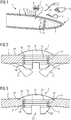
- Fig. 1 shows a partial principle sketch of an inventive rotor blade 1, comprising a hollow blade body 2 with a hollow inner 3, which runs from a (not shown) root at the left end of the rotor blade 1 to a tip 4.
- the tip 4 is also hollow but for example filled with a stiffening material 5.
- At least one drain hole 6 is provided having a circular cross section.
- This drain hole 6 allows access into the inner 3 of the blade body 2. It can be closed by inserting a plug-like closing means 7 which is after insertion also removable, as depicted by means of a double arrow P1.
- the plug-like closing means 7 comprises at least one drain bore 8, which is shown by the dashed lines in fig. 1 .
- the drain hole 6 can be closed, but can also be opened for maintenance purpose or the like, as shown in fig. 1 .
- this maintenance purpose see arrow P2
- a vacuum cleaner 13 respectively its hose 14 to the blade body 2 and to suck any dirt 11 or pieces 12 out of the inner 3 through the drain hole 6.
- the endoscopic camera 9, the hand 10 and the vacuum cleaner 13 are only shown in principle but not in the real size.
- the drain hole 6 itself may have a relatively large diameter, the diameter is at least 10 mm, preferably at least 20 mm and most preferably at least 25 mm. It may also have a remarkably larger diameter of for example 50 mm, 80 mm, or 100 mm. As the drain hole 6 is closed by the plug-like closing means 7 it is closed during operation of the wind turbine avoiding any noise or avoiding any dirt or water entering through the hole, while water can be drained through the drain bore 7. As said, for maintenance purposes the plug-like closing means 7 may easily be removed.
- Fig. 2 shows a first embodiment with a more detailed plug-like closing means 7.
- This closing means 7 comprises a cylindrical body 15 having an engagement means 16 like a clamping or snap-in outer structure with several clamping or snapping ribs being provided at the outer circumference of the cylindrical body 13.
- the engagement means 16 like the snap-in or clamping means respectively ribs firmly clamp against the inner circumference 17 of the drain hole 6 for firmly fixing the plug-like closing means 7 in the drain hole 6.
- the plug-like closing means 7 further comprises a head 18, in this embodiment a lens-shaped head, which abuts against the outer surface 19 of the blade body 2. So it is obvious that this plug-like closing means 7 can easily be pushed and fixed in the drain hole 6, but may also easily be removed again, as it is, like in all embodiments, preferably made of polymer respectively plastic.
- Fig. 3 shows another embodiment of a plug-like closing means 7, which again comprises a cylindrical body 15 with respective engagement means 16 like circular ribs, which clamp against the inner circumference 17 of the drain hole 6.
- the engagement means 16 comprise a snapping shoulder 20, which engages behind the shoulder 21 surrounding the drain bore 6.
- a lens-shaped head is provided, which engages into a recess 22 provided in the outer surface 19 of the blade body 2, so that the lens-shaped head 16 very smoothly is fitted into the surface 19.
- the circular body 15 is provided with at least two axial slits 23 providing a certain elasticity of the circular body 15 for an easy insertion into the drain bore 6.
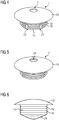
- Fig. 4 shows a perspective view of a first embodiment of a plug-like closing means 7 comprising the cylindrical body 15 with the engagement means 16 in form of several circular ribs and the slits 23. Also shown is the lens-shaped head 18 and the drain bore 8, which extends through the head 18.
- the circular body 15, as shown, is hollow respectively comprises a large central bore, which communicates with the respective bore or opening in the head 18 defining the drain bore 8.
- the plug-like closing means 7 also comprises a respective circular body 15 with the respective engagement means 16 in form of ribs and a lens-shaped head 18.
- the hollow circular body 15 is filled with a noise reducing, but water permeable means 24, preferably an open foam piece. This means 24 is inserted into the large central bore of the circular body 15 and extends until the inner bottom side of the head 18.
- FIG. 8 Another embodiment of a plug-like closing means 7 is shown in fig. 8 .
- the lens-shaped head 18 comprises several drain bores 8, which communicate with the central bore of the cylindrical body 15.
- a very large drain bore 8 is provided in the lens-shaped head 18. Again a noise reducing, but water permeable means 24 in form of a foam piece is inserted into the closing means 7, which fills the central bore in the circular body 15 and the respective bore in the head 18.
- Fig. 9 shows an embodiment of a plug-like closing means 7 in a cross sectional view.
- a fixation and/or sealing means 25 like a tape or the like is provided, which abuts at the outer surface of the blade body 2, for example of the surface of the recess 22 or the like.
- the drain hole 8 extending through the whole closing element 7 is shown.
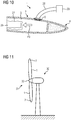
- Fig. 10 shows a situation, when the rotor blade 1 respectively the blade body 2 is produced.
- a mandrel 26 used for forming the hollow blade body 2 and which comprises a vacuum bag 27 is pulled out of the hollow blade body 2, as shown by the arrow P3.
- an air hose 28 attached to an air pump 29 to the drain hole 6 for pumping air in the inner 3 of the blade body 2 to avoid any negative pressure and to support the pulling action.
- FIG. 11 shows a wind turbine 30 comprising a rotor 31 with a hub 32, to which in this embodiment several rotor blades 1 according to the invention are attached.
- Each rotor blade comprises at least one plug-like closing means 7 inserted into a respective drain hole 6.
Landscapes
- Engineering & Computer Science (AREA)
- Life Sciences & Earth Sciences (AREA)
- Sustainable Development (AREA)
- Sustainable Energy (AREA)
- Chemical & Material Sciences (AREA)
- Combustion & Propulsion (AREA)
- Mechanical Engineering (AREA)
- General Engineering & Computer Science (AREA)
- Structures Of Non-Positive Displacement Pumps (AREA)
Abstract
Description
- The invention relates to a rotor blade for a wind turbine, comprising an at least partially hollow blade body extending from a root to a tip, which blade body is provided with at least one drain hole connecting the hollow inner with the outer surrounding, which drain hole is positioned in an area close to the tip.
- A wind turbine usually comprises several rotor blades attached to a hub. When wind acts on the rotor blades the hub starts to rotate and drives a generator connected to the hub for producing electrical energy.
- A rotor blade usually comprises an at least partially hollow blade body, which extends from a root, which is fixed to the hub, to a tip. Over its length the blade body changes its cross section from a usually circular cross section at the root to an air foil cross section.
- As the blade body is hollow water can accumulate in the blade body due to condensation or a direct ingress, which water needs to be drained. If the water is not drained it may freeze and damage the rotor blade.
- To drain the water it is known, see for example
EP 1 607 623 A2 , to provide at least one drain hole in the area of the tip, which connects the hollow inner of the rotor blade body with the outer surrounding. Through this drain hole the water can be drained from the inner to the outer surrounding. Such a drain hole, seeEP 1 607 623 A2 , has a very small diameter of less than 1 cm, preferably 5 mm. - The drain hole in the rotor blade disclosed in
EP 1 607 623 A2 has the only purpose to drain water. For avoiding that dirt or loose pieces in the hollow blade body clog the drain hole a net or the like is provided in the inner of the blade body at a position spaced apart from the drain hole, which net is water permeable but holds back any dirt or material which may clog the drain hole. For allowing a removal of any collected material by hand a hand hole is provided which is closed by means of a lid, through which hand hole for maintenance purpose the worker can reach with his hand into the inner of the hollow blade body for cleaning the net. - It is an object of the invention to provide an improved rotor blade.
- For solving the problem a rotor blade as depicted above is characterised in that the drain hole is closed with a removable plug-like closing means having at least one drain bore.
- While in the prior art the drain holes are bores with a very small diameter, which are permanently open to the surrounding, the invention proposes to provide a drain hole into which a removable plug-like closing means is inserted. This closing means has at least one drain bore, which is permanently open and which connects the inner of the blade body to the outer surrounding allowing to drain any accumulated water. So this plug-like closing means permanently allows for draining water, while on the other hand it is possible to provide a way larger drain hole in the blade body, which drain hole preferably has a diameter of at least 10 mm, preferably of at least 20 mm and especially of at least 25 mm. As the plug-like closing means is removable, it is at any time possible to remove it from the drain hole and open the drain hole, which provides a relatively large access hole to the inner of the blade body. This makes the drain hole a multifunctional hole, which does not only act as a drain hole, but also allows to for example perform a camera inspection by inserting a small camera like an endoscope through the drain hole in the inner of the blade body, or to remove any dirt or pieces which have accumulated in the tip area for example by means of a vacuum cleaner comprising a hose which can be inserted through the drain hole in the inner of the blade body or even to remove any items by hand. Any such item may for example be a piece of a vacuum bag arranged in the inner of the blade body or the like. Furthermore it is also possible to press air through this drain hole into the inner of the blade body during the manufacturing process, when a mandrel is pulled out of the blade body usually creating a negative pressure in the tip area which makes the pulling of the mandrel cumbersome. By pressing air in the blade body from the tip end the mandrel can be pulled easily.
- After finishing the maintenance the drain hole is simply closed again by inserting the plug-like closing means again, closing the large drain hole but still providing a possibility for draining water through the at least one drain bore in the closing means.
- As mentioned, the drain hole has preferably a diameter of at least 10 mm, preferably of at least 22 mm and especially of at least 25 mm, depending on the size of items which shall be connected to the drain hole or shall be inserted into the drain hole. A diameter of for example 40 or 50 mm or even up to 100 mm is also possible.
- While it is possible that the plug-like closing means comprises only one drain bore, usually provided in the center of the circular closing means which is inserted in the circular drain hole, it is certainly possible to provide multiple drain bores, which perforate the closing means.
- The plug-like closing means itself preferably comprises a cylindrical body having a head, preferably a lens-shaped head, with the at least one drain bore extending through the body and the head. The cylindrical body is inserted into the drain hole and preferably clamps at the inner of the drain hole or extends through the drain hole and clamps at the inner shoulder. At least one central bore extends through the body and through the head, which rests on the outside of the blade body, preferably in a recess, so that it is smoothly integrated into the outer surface of the blade body. This head may have a flat surface or design, it preferably may also have lens-shaped design or outer surface.
- If multiple drain bores are provided, these multiple bores are provided in the head, while the cylindrical body comprises only one central bore communicating with all multiple drain bores.
- As already mentioned, the closing means, when mounted, preferably engages with its head, preferably its lens-shaped head into a recess formed in the outer surface of the blade body, so that it is smoothly integrated in the outer body surface.
- A fixation and/or sealing material may be arranged at the bottom of the head, which fixation and/or sealing means may be an elastic or sticky tape which abuts the adjacent surface of the blade body respectively the recess.
- The cylindrical body of the plug-shaped closing means may comprise one or more axially extending slits, which make the cylindrical body more elastic for allowing it to firmly fit into the drain hole.
- Preferably the drain bore is at least partially filled with a noise reducing and water permeable means, which means is preferably a foam piece. This noise reducing means reduces noise which may be caused by the open hole when the blade rotates, but does not hamper the draining of the water, as it is water permeable. As the water is driven out due to the centrifugal forces when the rotor blades rotate, the water is pressed through this means.
- For firmly fixing the plug-like closing means at the blade body respectively in the drain hole the closing means preferably has at least one engagement means engaging with the blade body for fixing the closing means in the drain hole.
- This engagement means may comprise at least one snap-in means clamping towards the inner of the drain bore or snapping at the inner shoulder of the drain bore. So for fixing the closing means it is simply firmly pressed in the drain hole, with the engagement means, for example one or several clamping rips or lips or the like extending radially from the circular body, firmly clamp at the inner circumference of the drain bore. The engagement means or snap-in means may also comprise one or more snap noses provided in the end of the cylindrical body, which nose or noses engage behind the inner shoulder of the drain bore.
- As the clamping means is preferably made of a polymer, it has a certain elasticity allowing a firm clamp or snap fixation on the one hand, but also the simple removal of the plug-like means on the other hand.
- Aside the rotor blade itself the invention furthermore relates to a wind turbine, comprising a rotor with one or more rotor blades as depicted above.
- Further advantages of the invention become apparent from the following detailed description and the respective drawings. The drawings show:
- Fig. 1
- shows a principle partial drawing of an inventive rotor blade,
- Fig. 2
- an enlarged view of an inserted plug-like closing means in a first embodiment,
- Fig. 3
- an enlarged view of an inserted plug-like closing means in a second embodiment,
- Fig. 4
- a perspective view of a plug-like closing means of a first embodiment,
- Fig. 5
- a perspective view of a plug-like closing means of a second embodiment,
- Fig. 6
- a side view of the plug-like closing means of
fig. 5 , - Fig. 7
- a perspective view of a plug-like closing means of a third embodiment,
- Fig. 8
- a perspective view of a plug-like closing means of a fourth embodiment,
- Fig. 9
- a cross sectional view of a plug-like closing means of a fifth embodiment,
- Fig. 10
- a principle drawing of the inventive rotor blade during manufacturing when the mandrel is pulled out, and
- Fig. 11
- a principle drawing of a wind turbine.
-
Fig. 1 shows a partial principle sketch of an inventive rotor blade 1, comprising ahollow blade body 2 with ahollow inner 3, which runs from a (not shown) root at the left end of the rotor blade 1 to atip 4. Thetip 4 is also hollow but for example filled with a stiffeningmaterial 5. - In the
blade body 2 at least onedrain hole 6 is provided having a circular cross section. Thisdrain hole 6 allows access into the inner 3 of theblade body 2. It can be closed by inserting a plug-like closing means 7 which is after insertion also removable, as depicted by means of a double arrow P1. The plug-like closing means 7 comprises at least onedrain bore 8, which is shown by the dashed lines infig. 1 . - So the
drain hole 6 can be closed, but can also be opened for maintenance purpose or the like, as shown infig. 1 . During this maintenance purpose (see arrow P2) it is for example possible to insert an endoscopic camera 9 for a camera inspection of the inner 3 of theblade body 2, or to grab with ahand 10 into the inner 3 for removingdirt 11 orloose pieces 12 maybe from a vacuum bag or the like. Finally it is possible to attach avacuum cleaner 13 respectively itshose 14 to theblade body 2 and to suck anydirt 11 orpieces 12 out of the inner 3 through thedrain hole 6. The endoscopic camera 9, thehand 10 and thevacuum cleaner 13 are only shown in principle but not in the real size. - The
drain hole 6 itself may have a relatively large diameter, the diameter is at least 10 mm, preferably at least 20 mm and most preferably at least 25 mm. It may also have a remarkably larger diameter of for example 50 mm, 80 mm, or 100 mm. As thedrain hole 6 is closed by the plug-like closing means 7 it is closed during operation of the wind turbine avoiding any noise or avoiding any dirt or water entering through the hole, while water can be drained through thedrain bore 7. As said, for maintenance purposes the plug-like closing means 7 may easily be removed. -
Fig. 2 shows a first embodiment with a more detailed plug-like closing means 7. This closing means 7 comprises acylindrical body 15 having an engagement means 16 like a clamping or snap-in outer structure with several clamping or snapping ribs being provided at the outer circumference of thecylindrical body 13. The engagement means 16 like the snap-in or clamping means respectively ribs firmly clamp against theinner circumference 17 of thedrain hole 6 for firmly fixing the plug-like closing means 7 in thedrain hole 6. - The plug-like closing means 7 further comprises a
head 18, in this embodiment a lens-shaped head, which abuts against theouter surface 19 of theblade body 2. So it is obvious that this plug-like closing means 7 can easily be pushed and fixed in thedrain hole 6, but may also easily be removed again, as it is, like in all embodiments, preferably made of polymer respectively plastic. - As
fig. 2 shows,loose pieces 12 have accumulated in the area of thedrain hole 6, which, when the plug-like closing means 7 is removed, can easily be taken out of the inner 3 of theblade body 2. -
Fig. 3 shows another embodiment of a plug-like closing means 7, which again comprises acylindrical body 15 with respective engagement means 16 like circular ribs, which clamp against theinner circumference 17 of thedrain hole 6. In this embodiment at the inner end of the plug-like closing means the engagement means 16 comprise a snappingshoulder 20, which engages behind theshoulder 21 surrounding thedrain bore 6. At the other end of the plug-like closing means 7 a lens-shaped head is provided, which engages into arecess 22 provided in theouter surface 19 of theblade body 2, so that the lens-shapedhead 16 very smoothly is fitted into thesurface 19. - As also shown in this embodiment, the
circular body 15 is provided with at least twoaxial slits 23 providing a certain elasticity of thecircular body 15 for an easy insertion into thedrain bore 6. -
Fig. 4 shows a perspective view of a first embodiment of a plug-like closing means 7 comprising thecylindrical body 15 with the engagement means 16 in form of several circular ribs and theslits 23. Also shown is the lens-shapedhead 18 and the drain bore 8, which extends through thehead 18. Thecircular body 15, as shown, is hollow respectively comprises a large central bore, which communicates with the respective bore or opening in thehead 18 defining thedrain bore 8. - In the embodiment of
figures 5 and 6 the plug-like closing means 7 also comprises a respectivecircular body 15 with the respective engagement means 16 in form of ribs and a lens-shapedhead 18. Here the hollowcircular body 15 is filled with a noise reducing, but water permeable means 24, preferably an open foam piece. This means 24 is inserted into the large central bore of thecircular body 15 and extends until the inner bottom side of thehead 18. - Another embodiment of a plug-like closing means 7 is shown in
fig. 8 . Here the lens-shapedhead 18 comprises several drain bores 8, which communicate with the central bore of thecylindrical body 15. - Finally in the embodiment of
fig. 8 a verylarge drain bore 8 is provided in the lens-shapedhead 18. Again a noise reducing, but water permeable means 24 in form of a foam piece is inserted into the closing means 7, which fills the central bore in thecircular body 15 and the respective bore in thehead 18. -
Fig. 9 shows an embodiment of a plug-like closing means 7 in a cross sectional view. At the bottom side of the lens-shaped head 18 a fixation and/or sealing means 25 like a tape or the like is provided, which abuts at the outer surface of theblade body 2, for example of the surface of therecess 22 or the like. In this embodiment also thedrain hole 8 extending through thewhole closing element 7 is shown. -
Fig. 10 shows a situation, when the rotor blade 1 respectively theblade body 2 is produced. Amandrel 26 used for forming thehollow blade body 2 and which comprises avacuum bag 27 is pulled out of thehollow blade body 2, as shown by the arrow P3. As this pulling leads to a negative pressure at the tip side it is possible to attach anair hose 28 attached to anair pump 29 to thedrain hole 6 for pumping air in the inner 3 of theblade body 2 to avoid any negative pressure and to support the pulling action. - Finally
fig. 11 shows awind turbine 30 comprising arotor 31 with ahub 32, to which in this embodiment several rotor blades 1 according to the invention are attached. Each rotor blade comprises at least one plug-like closing means 7 inserted into arespective drain hole 6. - Although the present invention has been described in detail with reference to the preferred embodiment, the present invention is not limited by the disclosed examples from which the skilled person is able to derive other variations without departing from the scope of the invention.
Claims (14)
- Rotor blade for a wind turbine (30), comprising an at least partially hollow blade body (2) extending from a root to a tip (4), which blade body (2) is provided with at least one drain hole (6) connecting the hollow inner (3) with the outer surrounding, which drain hole (6) is positioned in an area close to the tip (4), characterised in that the drain hole (6) is closed with a removable plug-like closing means (7) having at least one drain bore (8).
- Rotor blade according to claim 1, characterising in that the drain hole (6) has a diameter of at least 10 mm, preferably of at least 20 mm and especially of at least 25 mm.
- Rotor blade according to claim 1 or 2, characterised in that the plug-like closing means (7) is provided with multiple drain bores (8).
- Rotor blade according to one of the preceding claims, characterised in that the plug-like closing means (7) comprises a cylindrical body (15) and a, preferably lens-shaped, head (18) with the at least one drain bore (8) extending through the body (15) and the head (18).
- Rotor blade according to claim 3 and 4, characterised in that the multiple drain bores (8) are provided in the head (18), while the cylindrical body (15) comprises only one central bore communicating with the multiple drain bores (8).
- Rotor blade according to claims 4 or 5, characterised in that the closing means (7), when mounted, engages with its head (18) into a recess (22) formed in the outer surface (19) of the blade body (2).
- Rotor blade according to one of the claims 4 to 6, characterised in that a fixation and/or sealing material (25) is arranged at the bottom of the head (18).
- Rotor blade according to one of the claims 4 to 7, characterised in that the cylindrical body (15) comprises one or more axially extending slits (23).
- Rotor blade according to one of the preceding claims, characterised in that the at least one drain bore (8) is at least partially filled with a noise reducing and water permeable means (24).
- Rotor blade according to claim 9, characterised in that the means (24) is a foam piece.
- Rotor blade according to one of the preceding claims, characterised in that the plug-like closing means (7) has at least one engagement means (16) engaging with the blade body (2) for fixing the closing means (7) in the drain hole (6).
- Rotor blade according to claim 11, characterised in that the engagement means (16) comprises at least one snap-in means or clamping clamping towards the inner of the drain bore (6) or clamping at the inner shoulder of the drain bore (6).
- Rotor blade according to one of the preceding claims, characterised in that the closing means (7) is made of a polymer.
- Wind turbine, comprising a rotor (31) with one or more rotor blades (1) according to one of the preceding claims.
Priority Applications (2)
| Application Number | Priority Date | Filing Date | Title |
|---|---|---|---|
| EP19164164.6A EP3712422B1 (en) | 2019-03-20 | 2019-03-20 | Rotor blade for a wind turbine |
| DK19164164.6T DK3712422T3 (en) | 2019-03-20 | 2019-03-20 | ROTOR BLADE FOR A WINDMILL |
Applications Claiming Priority (1)
| Application Number | Priority Date | Filing Date | Title |
|---|---|---|---|
| EP19164164.6A EP3712422B1 (en) | 2019-03-20 | 2019-03-20 | Rotor blade for a wind turbine |
Publications (2)
| Publication Number | Publication Date |
|---|---|
| EP3712422A1 true EP3712422A1 (en) | 2020-09-23 |
| EP3712422B1 EP3712422B1 (en) | 2023-10-11 |
Family
ID=65894896
Family Applications (1)
| Application Number | Title | Priority Date | Filing Date |
|---|---|---|---|
| EP19164164.6A Active EP3712422B1 (en) | 2019-03-20 | 2019-03-20 | Rotor blade for a wind turbine |
Country Status (2)
| Country | Link |
|---|---|
| EP (1) | EP3712422B1 (en) |
| DK (1) | DK3712422T3 (en) |
Cited By (2)
| Publication number | Priority date | Publication date | Assignee | Title |
|---|---|---|---|---|
| US20220090583A1 (en) * | 2019-01-08 | 2022-03-24 | Siemens Gamesa Renewable Energy Service Gmbh | Wind turbine and method for operating a wind turbine |
| US11549483B2 (en) * | 2020-03-02 | 2023-01-10 | Nordex Energy Se & Co. Kg | Rotor blade for a wind turbine and rotor blade tip |
Families Citing this family (1)
| Publication number | Priority date | Publication date | Assignee | Title |
|---|---|---|---|---|
| EP4628727A1 (en) * | 2024-04-02 | 2025-10-08 | LM Wind Power A/S | Wind turbine blades, methods and inspection devices |
Citations (6)
| Publication number | Priority date | Publication date | Assignee | Title |
|---|---|---|---|---|
| EP1342009A1 (en) * | 2000-12-13 | 2003-09-10 | Lm Glasfiber A/S | Wind turbine rotor blade with combined lightning receptor and drain passage and lightning receptor with drain passage |
| JP2005105916A (en) * | 2003-09-30 | 2005-04-21 | Daiwa House Ind Co Ltd | Drainage mechanism for windmill blade |
| EP1607623A2 (en) | 2004-06-15 | 2005-12-21 | NORDEX ENERGY GmbH | Rotor blade for wind turbine |
| DE102008048617A1 (en) * | 2008-09-23 | 2010-04-01 | Repower Systems Ag | Rotor blade for wind power plant, has drain opening at region of rotor-blade tip, where drain opening is hole in wall of blade, comprises opening width of larger or same as specific range and is arranged at suction side of blade |
| EP2722522A1 (en) * | 2012-10-22 | 2014-04-23 | Siemens Aktiengesellschaft | Lightning receptor arrangement for a wind turbine rotor blade |
| US20150064003A1 (en) * | 2013-08-27 | 2015-03-05 | General Electric Company | Airflow modifying element for suppressing airflow noise |
Family Cites Families (1)
| Publication number | Priority date | Publication date | Assignee | Title |
|---|---|---|---|---|
| US7942640B2 (en) * | 2009-03-19 | 2011-05-17 | General Electric Company | Method and apparatus for use in protecting wind turbine blades from lightning damage |
-
2019
- 2019-03-20 EP EP19164164.6A patent/EP3712422B1/en active Active
- 2019-03-20 DK DK19164164.6T patent/DK3712422T3/en active
Patent Citations (6)
| Publication number | Priority date | Publication date | Assignee | Title |
|---|---|---|---|---|
| EP1342009A1 (en) * | 2000-12-13 | 2003-09-10 | Lm Glasfiber A/S | Wind turbine rotor blade with combined lightning receptor and drain passage and lightning receptor with drain passage |
| JP2005105916A (en) * | 2003-09-30 | 2005-04-21 | Daiwa House Ind Co Ltd | Drainage mechanism for windmill blade |
| EP1607623A2 (en) | 2004-06-15 | 2005-12-21 | NORDEX ENERGY GmbH | Rotor blade for wind turbine |
| DE102008048617A1 (en) * | 2008-09-23 | 2010-04-01 | Repower Systems Ag | Rotor blade for wind power plant, has drain opening at region of rotor-blade tip, where drain opening is hole in wall of blade, comprises opening width of larger or same as specific range and is arranged at suction side of blade |
| EP2722522A1 (en) * | 2012-10-22 | 2014-04-23 | Siemens Aktiengesellschaft | Lightning receptor arrangement for a wind turbine rotor blade |
| US20150064003A1 (en) * | 2013-08-27 | 2015-03-05 | General Electric Company | Airflow modifying element for suppressing airflow noise |
Cited By (3)
| Publication number | Priority date | Publication date | Assignee | Title |
|---|---|---|---|---|
| US20220090583A1 (en) * | 2019-01-08 | 2022-03-24 | Siemens Gamesa Renewable Energy Service Gmbh | Wind turbine and method for operating a wind turbine |
| US11519391B2 (en) * | 2019-01-08 | 2022-12-06 | Siemens Gamesa Renewable Energy Service Gmbh | Wind turbine and method for operating a wind turbine |
| US11549483B2 (en) * | 2020-03-02 | 2023-01-10 | Nordex Energy Se & Co. Kg | Rotor blade for a wind turbine and rotor blade tip |
Also Published As
| Publication number | Publication date |
|---|---|
| DK3712422T3 (en) | 2023-11-27 |
| EP3712422B1 (en) | 2023-10-11 |
Similar Documents
| Publication | Publication Date | Title |
|---|---|---|
| EP3712422B1 (en) | Rotor blade for a wind turbine | |
| US9557132B2 (en) | Fryer drain cleaner | |
| US9549854B1 (en) | Safety cleaning tip | |
| JP2020534119A5 (en) | ||
| EP3158901B1 (en) | Coffee machine assembly | |
| JP6304990B2 (en) | Drainage pump | |
| CA2886039C (en) | A device for taking a glove on and off, and a glove | |
| EP2698084A1 (en) | Device for obtaining juice directly from the fruit | |
| USD924871S1 (en) | Electronic device | |
| FR2760633A1 (en) | STICK-HAND CURETTING INSTRUMENT | |
| CN101091055A (en) | A wind turbine blade with a collection device inside | |
| CN204702965U (en) | For the draining pump of the especially drainage equipment of the household electrical appliance of washing machine | |
| US7476231B2 (en) | Obstetrical vacuum extractor | |
| EP3609370B1 (en) | A glove and a method of manufacturing a glove | |
| KR20130004683A (en) | A device for collecting a plastic cover of umbrella | |
| CN207003574U (en) | The scupper hose of wash basin | |
| KR100689112B1 (en) | Garlic Peel Discharge Device | |
| KR101845962B1 (en) | collection apparatus for separating vinyl bag of umbrella | |
| KR200436765Y1 (en) | Scalp removal cap | |
| US20230165410A1 (en) | Hair Collection Device | |
| JP2000234858A (en) | Dewatering device for wet umbrella | |
| KR200458283Y1 (en) | Sap Extractor for Sap Collection | |
| CN223780587U (en) | Draining pump | |
| JPH0447579Y2 (en) | ||
| JP4125327B2 (en) | Air conditioner cleaning device and air conditioner |
Legal Events
| Date | Code | Title | Description |
|---|---|---|---|
| PUAI | Public reference made under article 153(3) epc to a published international application that has entered the european phase |
Free format text: ORIGINAL CODE: 0009012 |
|
| STAA | Information on the status of an ep patent application or granted ep patent |
Free format text: STATUS: THE APPLICATION HAS BEEN PUBLISHED |
|
| AK | Designated contracting states |
Kind code of ref document: A1 Designated state(s): AL AT BE BG CH CY CZ DE DK EE ES FI FR GB GR HR HU IE IS IT LI LT LU LV MC MK MT NL NO PL PT RO RS SE SI SK SM TR |
|
| AX | Request for extension of the european patent |
Extension state: BA ME |
|
| STAA | Information on the status of an ep patent application or granted ep patent |
Free format text: STATUS: REQUEST FOR EXAMINATION WAS MADE |
|
| 17P | Request for examination filed |
Effective date: 20210319 |
|
| RBV | Designated contracting states (corrected) |
Designated state(s): AL AT BE BG CH CY CZ DE DK EE ES FI FR GB GR HR HU IE IS IT LI LT LU LV MC MK MT NL NO PL PT RO RS SE SI SK SM TR |
|
| STAA | Information on the status of an ep patent application or granted ep patent |
Free format text: STATUS: EXAMINATION IS IN PROGRESS |
|
| 17Q | First examination report despatched |
Effective date: 20220421 |
|
| GRAP | Despatch of communication of intention to grant a patent |
Free format text: ORIGINAL CODE: EPIDOSNIGR1 |
|
| STAA | Information on the status of an ep patent application or granted ep patent |
Free format text: STATUS: GRANT OF PATENT IS INTENDED |
|
| INTG | Intention to grant announced |
Effective date: 20230512 |
|
| GRAS | Grant fee paid |
Free format text: ORIGINAL CODE: EPIDOSNIGR3 |
|
| GRAA | (expected) grant |
Free format text: ORIGINAL CODE: 0009210 |
|
| STAA | Information on the status of an ep patent application or granted ep patent |
Free format text: STATUS: THE PATENT HAS BEEN GRANTED |
|
| AK | Designated contracting states |
Kind code of ref document: B1 Designated state(s): AL AT BE BG CH CY CZ DE DK EE ES FI FR GB GR HR HU IE IS IT LI LT LU LV MC MK MT NL NO PL PT RO RS SE SI SK SM TR |
|
| REG | Reference to a national code |
Ref country code: GB Ref legal event code: FG4D |
|
| REG | Reference to a national code |
Ref country code: CH Ref legal event code: EP |
|
| REG | Reference to a national code |
Ref country code: DE Ref legal event code: R096 Ref document number: 602019038990 Country of ref document: DE |
|
| REG | Reference to a national code |
Ref country code: IE Ref legal event code: FG4D |
|
| REG | Reference to a national code |
Ref country code: DK Ref legal event code: T3 Effective date: 20231123 |
|
| REG | Reference to a national code |
Ref country code: LT Ref legal event code: MG9D |
|
| REG | Reference to a national code |
Ref country code: NL Ref legal event code: MP Effective date: 20231011 |
|
| REG | Reference to a national code |
Ref country code: AT Ref legal event code: MK05 Ref document number: 1620443 Country of ref document: AT Kind code of ref document: T Effective date: 20231011 |
|
| PG25 | Lapsed in a contracting state [announced via postgrant information from national office to epo] |
Ref country code: NL Free format text: LAPSE BECAUSE OF FAILURE TO SUBMIT A TRANSLATION OF THE DESCRIPTION OR TO PAY THE FEE WITHIN THE PRESCRIBED TIME-LIMIT Effective date: 20231011 |
|
| PG25 | Lapsed in a contracting state [announced via postgrant information from national office to epo] |
Ref country code: GR Free format text: LAPSE BECAUSE OF FAILURE TO SUBMIT A TRANSLATION OF THE DESCRIPTION OR TO PAY THE FEE WITHIN THE PRESCRIBED TIME-LIMIT Effective date: 20240112 |
|
| PG25 | Lapsed in a contracting state [announced via postgrant information from national office to epo] |
Ref country code: IS Free format text: LAPSE BECAUSE OF FAILURE TO SUBMIT A TRANSLATION OF THE DESCRIPTION OR TO PAY THE FEE WITHIN THE PRESCRIBED TIME-LIMIT Effective date: 20240211 |
|
| PG25 | Lapsed in a contracting state [announced via postgrant information from national office to epo] |
Ref country code: LT Free format text: LAPSE BECAUSE OF FAILURE TO SUBMIT A TRANSLATION OF THE DESCRIPTION OR TO PAY THE FEE WITHIN THE PRESCRIBED TIME-LIMIT Effective date: 20231011 |
|
| PG25 | Lapsed in a contracting state [announced via postgrant information from national office to epo] |
Ref country code: AT Free format text: LAPSE BECAUSE OF FAILURE TO SUBMIT A TRANSLATION OF THE DESCRIPTION OR TO PAY THE FEE WITHIN THE PRESCRIBED TIME-LIMIT Effective date: 20231011 |
|
| PG25 | Lapsed in a contracting state [announced via postgrant information from national office to epo] |
Ref country code: ES Free format text: LAPSE BECAUSE OF FAILURE TO SUBMIT A TRANSLATION OF THE DESCRIPTION OR TO PAY THE FEE WITHIN THE PRESCRIBED TIME-LIMIT Effective date: 20231011 |
|
| PG25 | Lapsed in a contracting state [announced via postgrant information from national office to epo] |
Ref country code: LT Free format text: LAPSE BECAUSE OF FAILURE TO SUBMIT A TRANSLATION OF THE DESCRIPTION OR TO PAY THE FEE WITHIN THE PRESCRIBED TIME-LIMIT Effective date: 20231011 Ref country code: IS Free format text: LAPSE BECAUSE OF FAILURE TO SUBMIT A TRANSLATION OF THE DESCRIPTION OR TO PAY THE FEE WITHIN THE PRESCRIBED TIME-LIMIT Effective date: 20240211 Ref country code: GR Free format text: LAPSE BECAUSE OF FAILURE TO SUBMIT A TRANSLATION OF THE DESCRIPTION OR TO PAY THE FEE WITHIN THE PRESCRIBED TIME-LIMIT Effective date: 20240112 Ref country code: ES Free format text: LAPSE BECAUSE OF FAILURE TO SUBMIT A TRANSLATION OF THE DESCRIPTION OR TO PAY THE FEE WITHIN THE PRESCRIBED TIME-LIMIT Effective date: 20231011 Ref country code: BG Free format text: LAPSE BECAUSE OF FAILURE TO SUBMIT A TRANSLATION OF THE DESCRIPTION OR TO PAY THE FEE WITHIN THE PRESCRIBED TIME-LIMIT Effective date: 20240111 Ref country code: AT Free format text: LAPSE BECAUSE OF FAILURE TO SUBMIT A TRANSLATION OF THE DESCRIPTION OR TO PAY THE FEE WITHIN THE PRESCRIBED TIME-LIMIT Effective date: 20231011 Ref country code: PT Free format text: LAPSE BECAUSE OF FAILURE TO SUBMIT A TRANSLATION OF THE DESCRIPTION OR TO PAY THE FEE WITHIN THE PRESCRIBED TIME-LIMIT Effective date: 20240212 |
|
| PG25 | Lapsed in a contracting state [announced via postgrant information from national office to epo] |
Ref country code: SE Free format text: LAPSE BECAUSE OF FAILURE TO SUBMIT A TRANSLATION OF THE DESCRIPTION OR TO PAY THE FEE WITHIN THE PRESCRIBED TIME-LIMIT Effective date: 20231011 Ref country code: RS Free format text: LAPSE BECAUSE OF FAILURE TO SUBMIT A TRANSLATION OF THE DESCRIPTION OR TO PAY THE FEE WITHIN THE PRESCRIBED TIME-LIMIT Effective date: 20231011 Ref country code: PL Free format text: LAPSE BECAUSE OF FAILURE TO SUBMIT A TRANSLATION OF THE DESCRIPTION OR TO PAY THE FEE WITHIN THE PRESCRIBED TIME-LIMIT Effective date: 20231011 Ref country code: NO Free format text: LAPSE BECAUSE OF FAILURE TO SUBMIT A TRANSLATION OF THE DESCRIPTION OR TO PAY THE FEE WITHIN THE PRESCRIBED TIME-LIMIT Effective date: 20240111 Ref country code: LV Free format text: LAPSE BECAUSE OF FAILURE TO SUBMIT A TRANSLATION OF THE DESCRIPTION OR TO PAY THE FEE WITHIN THE PRESCRIBED TIME-LIMIT Effective date: 20231011 Ref country code: HR Free format text: LAPSE BECAUSE OF FAILURE TO SUBMIT A TRANSLATION OF THE DESCRIPTION OR TO PAY THE FEE WITHIN THE PRESCRIBED TIME-LIMIT Effective date: 20231011 |
|
| REG | Reference to a national code |
Ref country code: DE Ref legal event code: R097 Ref document number: 602019038990 Country of ref document: DE |
|
| PG25 | Lapsed in a contracting state [announced via postgrant information from national office to epo] |
Ref country code: CZ Free format text: LAPSE BECAUSE OF FAILURE TO SUBMIT A TRANSLATION OF THE DESCRIPTION OR TO PAY THE FEE WITHIN THE PRESCRIBED TIME-LIMIT Effective date: 20231011 |
|
| PG25 | Lapsed in a contracting state [announced via postgrant information from national office to epo] |
Ref country code: SK Free format text: LAPSE BECAUSE OF FAILURE TO SUBMIT A TRANSLATION OF THE DESCRIPTION OR TO PAY THE FEE WITHIN THE PRESCRIBED TIME-LIMIT Effective date: 20231011 |
|
| PG25 | Lapsed in a contracting state [announced via postgrant information from national office to epo] |
Ref country code: SM Free format text: LAPSE BECAUSE OF FAILURE TO SUBMIT A TRANSLATION OF THE DESCRIPTION OR TO PAY THE FEE WITHIN THE PRESCRIBED TIME-LIMIT Effective date: 20231011 Ref country code: SK Free format text: LAPSE BECAUSE OF FAILURE TO SUBMIT A TRANSLATION OF THE DESCRIPTION OR TO PAY THE FEE WITHIN THE PRESCRIBED TIME-LIMIT Effective date: 20231011 Ref country code: RO Free format text: LAPSE BECAUSE OF FAILURE TO SUBMIT A TRANSLATION OF THE DESCRIPTION OR TO PAY THE FEE WITHIN THE PRESCRIBED TIME-LIMIT Effective date: 20231011 Ref country code: IT Free format text: LAPSE BECAUSE OF FAILURE TO SUBMIT A TRANSLATION OF THE DESCRIPTION OR TO PAY THE FEE WITHIN THE PRESCRIBED TIME-LIMIT Effective date: 20231011 Ref country code: EE Free format text: LAPSE BECAUSE OF FAILURE TO SUBMIT A TRANSLATION OF THE DESCRIPTION OR TO PAY THE FEE WITHIN THE PRESCRIBED TIME-LIMIT Effective date: 20231011 Ref country code: CZ Free format text: LAPSE BECAUSE OF FAILURE TO SUBMIT A TRANSLATION OF THE DESCRIPTION OR TO PAY THE FEE WITHIN THE PRESCRIBED TIME-LIMIT Effective date: 20231011 |
|
| PLBE | No opposition filed within time limit |
Free format text: ORIGINAL CODE: 0009261 |
|
| STAA | Information on the status of an ep patent application or granted ep patent |
Free format text: STATUS: NO OPPOSITION FILED WITHIN TIME LIMIT |
|
| 26N | No opposition filed |
Effective date: 20240712 |
|
| PG25 | Lapsed in a contracting state [announced via postgrant information from national office to epo] |
Ref country code: SI Free format text: LAPSE BECAUSE OF FAILURE TO SUBMIT A TRANSLATION OF THE DESCRIPTION OR TO PAY THE FEE WITHIN THE PRESCRIBED TIME-LIMIT Effective date: 20231011 |
|
| PG25 | Lapsed in a contracting state [announced via postgrant information from national office to epo] |
Ref country code: SI Free format text: LAPSE BECAUSE OF FAILURE TO SUBMIT A TRANSLATION OF THE DESCRIPTION OR TO PAY THE FEE WITHIN THE PRESCRIBED TIME-LIMIT Effective date: 20231011 |
|
| REG | Reference to a national code |
Ref country code: CH Ref legal event code: PL |
|
| PG25 | Lapsed in a contracting state [announced via postgrant information from national office to epo] |
Ref country code: LU Free format text: LAPSE BECAUSE OF NON-PAYMENT OF DUE FEES Effective date: 20240320 |
|
| PG25 | Lapsed in a contracting state [announced via postgrant information from national office to epo] |
Ref country code: MC Free format text: LAPSE BECAUSE OF FAILURE TO SUBMIT A TRANSLATION OF THE DESCRIPTION OR TO PAY THE FEE WITHIN THE PRESCRIBED TIME-LIMIT Effective date: 20231011 |
|
| PG25 | Lapsed in a contracting state [announced via postgrant information from national office to epo] |
Ref country code: MC Free format text: LAPSE BECAUSE OF FAILURE TO SUBMIT A TRANSLATION OF THE DESCRIPTION OR TO PAY THE FEE WITHIN THE PRESCRIBED TIME-LIMIT Effective date: 20231011 Ref country code: LU Free format text: LAPSE BECAUSE OF NON-PAYMENT OF DUE FEES Effective date: 20240320 |
|
| REG | Reference to a national code |
Ref country code: BE Ref legal event code: MM Effective date: 20240331 |
|
| PG25 | Lapsed in a contracting state [announced via postgrant information from national office to epo] |
Ref country code: BE Free format text: LAPSE BECAUSE OF NON-PAYMENT OF DUE FEES Effective date: 20240331 |
|
| PG25 | Lapsed in a contracting state [announced via postgrant information from national office to epo] |
Ref country code: IE Free format text: LAPSE BECAUSE OF NON-PAYMENT OF DUE FEES Effective date: 20240320 |
|
| PG25 | Lapsed in a contracting state [announced via postgrant information from national office to epo] |
Ref country code: IE Free format text: LAPSE BECAUSE OF NON-PAYMENT OF DUE FEES Effective date: 20240320 Ref country code: BE Free format text: LAPSE BECAUSE OF NON-PAYMENT OF DUE FEES Effective date: 20240331 Ref country code: CH Free format text: LAPSE BECAUSE OF NON-PAYMENT OF DUE FEES Effective date: 20240331 |
|
| PG25 | Lapsed in a contracting state [announced via postgrant information from national office to epo] |
Ref country code: CY Free format text: LAPSE BECAUSE OF FAILURE TO SUBMIT A TRANSLATION OF THE DESCRIPTION OR TO PAY THE FEE WITHIN THE PRESCRIBED TIME-LIMIT; INVALID AB INITIO Effective date: 20190320 |
|
| PG25 | Lapsed in a contracting state [announced via postgrant information from national office to epo] |
Ref country code: HU Free format text: LAPSE BECAUSE OF FAILURE TO SUBMIT A TRANSLATION OF THE DESCRIPTION OR TO PAY THE FEE WITHIN THE PRESCRIBED TIME-LIMIT; INVALID AB INITIO Effective date: 20190320 |
|
| PG25 | Lapsed in a contracting state [announced via postgrant information from national office to epo] |
Ref country code: FI Free format text: LAPSE BECAUSE OF FAILURE TO SUBMIT A TRANSLATION OF THE DESCRIPTION OR TO PAY THE FEE WITHIN THE PRESCRIBED TIME-LIMIT Effective date: 20231011 |
|
| PG25 | Lapsed in a contracting state [announced via postgrant information from national office to epo] |
Ref country code: TR Free format text: LAPSE BECAUSE OF FAILURE TO SUBMIT A TRANSLATION OF THE DESCRIPTION OR TO PAY THE FEE WITHIN THE PRESCRIBED TIME-LIMIT Effective date: 20231011 |
|
| PGFP | Annual fee paid to national office [announced via postgrant information from national office to epo] |
Ref country code: GB Payment date: 20260323 Year of fee payment: 8 |
|
| PGFP | Annual fee paid to national office [announced via postgrant information from national office to epo] |
Ref country code: DK Payment date: 20260323 Year of fee payment: 8 Ref country code: DE Payment date: 20250731 Year of fee payment: 8 |
|
| PGFP | Annual fee paid to national office [announced via postgrant information from national office to epo] |
Ref country code: FR Payment date: 20260323 Year of fee payment: 8 |