EP3712419B1 - Multi-valve device and valve arrangement - Google Patents
Multi-valve device and valve arrangement Download PDFInfo
- Publication number
- EP3712419B1 EP3712419B1 EP19290017.3A EP19290017A EP3712419B1 EP 3712419 B1 EP3712419 B1 EP 3712419B1 EP 19290017 A EP19290017 A EP 19290017A EP 3712419 B1 EP3712419 B1 EP 3712419B1
- Authority
- EP
- European Patent Office
- Prior art keywords
- valve
- air filter
- filter system
- air
- flexible
- Prior art date
- Legal status (The legal status is an assumption and is not a legal conclusion. Google has not performed a legal analysis and makes no representation as to the accuracy of the status listed.)
- Active
Links
Images

Classifications
-
- F—MECHANICAL ENGINEERING; LIGHTING; HEATING; WEAPONS; BLASTING
- F02—COMBUSTION ENGINES; HOT-GAS OR COMBUSTION-PRODUCT ENGINE PLANTS
- F02M—SUPPLYING COMBUSTION ENGINES IN GENERAL WITH COMBUSTIBLE MIXTURES OR CONSTITUENTS THEREOF
- F02M35/00—Combustion-air cleaners, air intakes, intake silencers, or induction systems specially adapted for, or arranged on, internal-combustion engines
- F02M35/02—Air cleaners
- F02M35/08—Air cleaners with means for removing dust, particles or liquids from cleaners; with means for indicating clogging; with by-pass means; Regeneration of cleaners
- F02M35/086—Dust removal by flushing, blasting, pulsating or aspirating flow, washing or the like; Mechanical dust removal, e.g. by using scrapers
-
- F—MECHANICAL ENGINEERING; LIGHTING; HEATING; WEAPONS; BLASTING
- F16—ENGINEERING ELEMENTS AND UNITS; GENERAL MEASURES FOR PRODUCING AND MAINTAINING EFFECTIVE FUNCTIONING OF MACHINES OR INSTALLATIONS; THERMAL INSULATION IN GENERAL
- F16K—VALVES; TAPS; COCKS; ACTUATING-FLOATS; DEVICES FOR VENTING OR AERATING
- F16K7/00—Diaphragm valves or cut-off apparatus, e.g. with a member deformed, but not moved bodily, to close the passage ; Pinch valves
- F16K7/02—Diaphragm valves or cut-off apparatus, e.g. with a member deformed, but not moved bodily, to close the passage ; Pinch valves with tubular diaphragm
- F16K7/04—Diaphragm valves or cut-off apparatus, e.g. with a member deformed, but not moved bodily, to close the passage ; Pinch valves with tubular diaphragm constrictable by external radial force
- F16K7/07—Diaphragm valves or cut-off apparatus, e.g. with a member deformed, but not moved bodily, to close the passage ; Pinch valves with tubular diaphragm constrictable by external radial force by means of fluid pressure
-
- B—PERFORMING OPERATIONS; TRANSPORTING
- B01—PHYSICAL OR CHEMICAL PROCESSES OR APPARATUS IN GENERAL
- B01D—SEPARATION
- B01D2279/00—Filters adapted for separating dispersed particles from gases or vapours specially modified for specific uses
- B01D2279/60—Filters adapted for separating dispersed particles from gases or vapours specially modified for specific uses for the intake of internal combustion engines or turbines
-
- B—PERFORMING OPERATIONS; TRANSPORTING
- B01—PHYSICAL OR CHEMICAL PROCESSES OR APPARATUS IN GENERAL
- B01D—SEPARATION
- B01D45/00—Separating dispersed particles from gases or vapours by gravity, inertia, or centrifugal forces
- B01D45/18—Cleaning-out devices
-
- B—PERFORMING OPERATIONS; TRANSPORTING
- B01—PHYSICAL OR CHEMICAL PROCESSES OR APPARATUS IN GENERAL
- B01D—SEPARATION
- B01D46/00—Filters or filtering processes specially modified for separating dispersed particles from gases or vapours
- B01D46/42—Auxiliary equipment or operation thereof
- B01D46/4272—Special valve constructions adapted to filters or filter elements
-
- B—PERFORMING OPERATIONS; TRANSPORTING
- B01—PHYSICAL OR CHEMICAL PROCESSES OR APPARATUS IN GENERAL
- B01D—SEPARATION
- B01D46/00—Filters or filtering processes specially modified for separating dispersed particles from gases or vapours
- B01D46/42—Auxiliary equipment or operation thereof
- B01D46/48—Removing dust other than cleaning filters, e.g. by using collecting trays
Definitions
- the invention relates to an air filter system comprising a multi-valve device for scavenging particulate dust, and a valve arrangement comprising a multi-valve device as well as a method for scavenging particulate dust from an air filter system.
- US 2010/0229972 A1 discloses an inertially activated ejection valve providing an inertially activated effluent ejector, and particularly an inertially activated dust ejector for an air induction system of an internal combustion engine in a vibratory system generating vibration.
- the vibration can be that of the engine itself, or a driven component such as an eccentric rotary driven weight.
- the dust ejection valve can be provided at various places in the air induction system of the internal combustion engine and is provided between the pre-cleaner and the air filter.
- US 2010/0229972 A1 further discloses a method for ejecting dust from an air induction system of an internal combustion engine in a vibratory system generating vibration.
- the method includes providing a dust ejection valve including an inertial mass, and inertially activating and driving the inertial mass by vibration to discharge dust from the air induction system.
- the method further includes providing the inertial mass as a plunger, and inertially driving the plunger by the vibration to vibrate and oscillate to an amplitude along an axial oscillation axis.
- the plunger inertial mass includes translating and oscillating the plunger inertial mass along an axial travel stroke in a channel extending along the oscillation axis, providing the plunger inertial mass with at least one valve face, providing the channel with at least one valve seat, and engaging the valve face and the valve seat at one end of the travel stroke.
- a flexible valve comprising an upper valve body, a lower valve body and a membrane sleeve, wherein the membrane sleeve is provided with a material conveying channel.
- the two ends of the membrane sleeve are connected with the upper valve body and the lower valve body correspondingly and the upper valve body or/and the lower valve body is/and connected in an axially-rotatable manner.
- US 4 820 315 A displays a unique vacuum loader and process to remove, collect, and dispose asbestos, hazardous material, and other particulate matter under continuous negative pressure.
- a top valve will remain open for a time period to fill the reservoir tube by about 50 percent.
- a lower valve will remain shut.
- the powder feeding device comprises a control device which is provided for selectively operating a dense phase powder pump in a powder conveying operating mode or a flushing operating mode.
- a powder inlet valve and the powder outlet valve of the dense phase powder pump are configured in each case as a pneumatically actuable compression valve which can be closed when an actuating pressure is applied.
- US 2006/0168958 A1 proposes a supercharged internal combustion engine system wherein the supercharger assembly includes an ejector pump driven by high-pressure air for pumping intake air into engine combustion chamber. During periods of natural engine aspiration the ejector pump can be by-passed to reduce flow impedance.
- EP 2 960 483 A1 proposes a dust discharge valve with an outlet opening and the dust separated during operation at least partially collected in a dust collection area in front of the outlet opening.
- the dust discharge valve has a closing element which is arranged on the outlet opening so that it can be opened in the outlet direction, and which keeps the outlet opening closed by a closing force during engine operation.
- the dust discharge valve can also be opened and/or released in a controlled and/or automated manner by means of an opening and/or blowing device.
- It is an object of the invention to provide an air filter system comprising a multi-valve device with a simple and robust operating performance for scavenging particulate dust, and comprising also a valve arrangement using said multi-valve device.
- a further object of the invention is to provide a method for scavenging particulate dust, from an air filter system with such a valve arrangement.
- an air filter system comprising a multi-valve device for scavenging particulate dust from the air filter system, comprising at least a first valve and a second valve arranged in series along a fluid path, to establish a collection volume for the particulate matter, wherein the first valve and the second valve each comprise a housing segment and a flexible membrane arranged inside the housing segment, wherein in each valve the flexible membrane is configured to close or open the fluid path through the valve, wherein the first valve and the second valve are configured to be connectable to a valve control unit for activating the flexible membranes independently from each other.
- a further object of the invention is achieved by the air filter system with a valve arrangement comprising a multi-valve device, the multi-valve device having at least a first and a second valve, wherein a valve control unit is provided for activating flexible membranes of valves of the multi-valve device independently from each other, and comprising a two-way valve for supplying the first valve with air and for supplying the second valve with air either, wherein the two-way valve being particularly a solenoid valve.
- a further object of the invention is achieved by a method for scavenging particulate dust from an air filter system, where a valve arrangement is connected to an outlet for particulate matter of the air filter system, the valve arrangement comprising a multi-valve device, the multi-valve device having at least a first and a second valve, wherein a valve control unit is provided for activating flexible membranes of valves of the multi-valve device independently from each other, and comprising a two-way valve for supplying the first valve with air and for supplying the second valve with air either, wherein the two-way valve being particularly a solenoid valve, the method comprising the air filter system operating in a first working phase with the first valve being open and the second valve being closed by the activated second flexible membrane for collecting particulate matter in a collection volume for the particulate matter, and the air filter system operating in a second working phase with the first valve being closed by the activated second flexible membrane and the second valve being open for scavenging particulate matter from the collection volume for the part
- an air filter system comprising a multi-valve device for scavenging particulate dust from the air filter system, comprising at least a first valve and a second valve arranged in series along a fluid path, to establish a collection volume for the particulate matter.
- the first valve and the second valve each comprise a housing segment and a flexible membrane arranged inside the housing segment. In each valve the flexible membrane is configured to close or open the fluid path through the valve.
- the first valve and the second valve are configured to be connectable to a valve control unit for activating the flexible membranes independently from each other.
- the inventive air filter system comprising a multi-valve device may advantageously be used for flow controlling along the fluid path for dust collecting and scavenging.
- the multi-valve device may comprise three subsystems. Two housing segments as bodies with a flexible membrane forming an inflatable chamber and a central connection component between the two housing segments. The central connection component keeps membranes on both sides in place and allows the fixation of an air admission system.
- the upper housing segment may comprise an inflatable pinch valve held with a clip connector.
- the clip connector may include an interface for air filter plugging.
- the lower housing segment may also comprise an inflatable membrane held by a clip connector.
- the air admission system may supply air pressure for inflating alternatively chambers of both membranes.
- the described air filter system comprising a multi-valve device may advantageously be used for heavy-duty tractors or construction machines.
- the device may be integrated at an air filter system in a vertical position or an angled position to a vertical direction. Connection to the air filter system may advantageously be achieved by a quick connector system.
- the multi-valve device is assembled from existing pinch valves for creating a dust collection volume and is used for dust pre-separation of an air filter.
- the flexible membranes of the pinch valves may be activated with pressure from a turbocharger when being integrated in an internal combustion engine.
- the first valve and/or the second valve are configured as a pinch valve.
- Pinch valves are commercially available in various dimensions, such that the multi-valve device may be assembled according to the dimensions of the air filter system where the multi-valve device is intended to collect and scavenge dust during operation of the air filter system. Such pinch valves are advantageously available also for robust working conditions and ambiences.
- a separation ring may be arranged in the collection volume for the particulate matter between the two membranes, being configured to secure the flexible membranes to an inner wall of the housing segments.
- the housing segments of the first valve and the second valve may be formed integrally.
- connection of the two valves may be facilitated.
- Further manufacturing of the multi-valve device may be achieved in an efficient and reliable manner. Sealing of the two valves to each other is intrinsically achieved.
- the first valve may comprise a first connector arranged opposite to the second valve with respect to the fluid path and/or the second valve may comprise a second connector arranged opposite to the first valve with respect to the fluid path.
- the connectors may serve for easy integration of the multi-valve device to an air filter system as well as to a dust collection system.
- Advantageously quick connectors may be used for easy connection and flexible changing of the multi-valve device in case of maintenance of the system.
- the air filter system with a valve arrangement comprising a multi-valve device.
- the multi-valve device has at least a first and a second valve.
- a valve control unit is provided for activating flexible membranes of valves of the multi-valve device independently from each other.
- the valve arrangement comprises a two-way valve for supplying the first valve with air and for supplying the second valve with air either.
- the two-way valve may particularly be a solenoid valve.
- the valve control unit together with the two-way valve may serve for activating the flexible membranes of the multi-valve device, thus controlling the functions of the scavenging an air filter system from particulate matter such as dust.
- the flexible membranes may be controlled pneumatically by the valve control unit, in particular by air pressure.
- Pneumatic control of the flexible membranes is a very efficient and fast reaction means for opening and closing the valves of the multi-valve device.
- Further air pressure from turbo-chargers may favorably be used, if integrating the valve arrangement in an internal combustion engine, particularly in heavy duty engines of construction machines.
- the valve control unit may be fixed to the interface region, in particular wherein the valve control unit may be fixed to a connection component located at the interface region.
- the valve control may easily be fixed to the multi-valve device for efficient assembling of the valve arrangement and easy maintenance. Further short distances between the valve control and the valves is advantageous for connecting air pipes from the valve control to the valves.
- a method for scavenging particulate dust from an air filter system.
- a valve arrangement is connected to an outlet for particulate matter of the air filter system.
- the valve arrangement comprises a multi-valve device, which has at least a first and a second valve.
- a valve control unit is provided for activating flexible membranes of valves of the multi-valve device independently from each other.
- the valve arrangement comprises a two-way valve for supplying the first valve with air and for supplying the second valve with air either.
- the two-way valve may particularly be a solenoid valve.
- the method comprises operating the air filter system in a first working phase with the first valve being open and the second valve being closed by the activated second flexible membrane for collecting particulate matter in a collection volume for the particulate matter, and operating the air filter system in a second working phase with the first valve being closed by the activated second flexible membrane and the second valve being open for scavenging particulate matter from the collection volume for the particulate matter along a fluid path through a second connector.
- the valve arrangement comprises a two-way valve for supplying the first valve with air and for supplying the second valve with air either.
- the two-way valve may particularly be a solenoid valve.
- the valve control unit together with the two-way valve may serve for activating the flexible membranes of the multi-valve device, thus controlling the functions of the scavenging an air filter system from particulate matter such as dust.
- the multi-valve device is used for flow controlling along the fluid path for dust collecting and scavenging.
- the air filter system comprising the multi-valve device may comprise three subsystems, i.e. two housing segments as bodies with a flexible membrane forming an inflatable chamber and a central connection component between the two housing segments.
- the central connection component keeps membranes on both sides in place and allows the fixation of an air admission system.
- the upper housing segment may comprise an inflatable pinch valve held with a clip connector.
- the clip connector may include an interface for air filter plugging.
- the lower housing segment may also comprise an inflatable membrane held by a clip connector.
- the air admission system may supply air pressure for inflating alternatively chambers of both membranes. When a chamber of a flexible membrane is supplied with air, the corresponding valve pipe is closed. By this way the inventive air filter system comprising a multi-valve device is used to collect dust from an air filter.
- the first valve adjacent to the air filter system may be open, thus representing in its inner space the collection volume for particulate dust, whereas the second valve connected in series is closed by inflating the chamber of the flexible membrane.
- the first valve adjacent to the air filter system may be closed by inflating the chamber of the corresponding membrane, whereas the second valve may be opened by deflating the chamber of the flexible membrane.
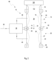
- Figure 1 depicts schematics of a valve arrangement 80 with a multi-valve device 10 according to an embodiment of the inventive air filter system 100 for scavenging particulate dust 46 from the air filter system 100.
- the valve arrangement 80 comprises the multi-valve device 10, consisting of a first and a second valve 12, 22.
- a valve control unit 34 as an air distributor system is provided for activating flexible membranes 16, 26 of the valves 12, 22 of the multi-valve device 10 independently from each other.
- the valve control 34 comprises a two-way valve 44, depicted in the embodiments shown in Figures 3 and 4 , for supplying the first valve 12 with air and for supplying the second valve 22 with air either via air pipes 38, 40 respectively, wherein the two-way valve 44 being particularly a solenoid valve.
- the first valve 12 and the second valve 22 are configured as a pinch valve each.
- the first valve 12 and the second valve 22 of the multi-valve device 10 are arranged in series along a fluid path 32, to establish a collection volume 30 for the particulate matter 46.
- the first valve 12 and the second valve 22 each comprise a housing segment 14, 24 and a flexible membrane 16, 26 arranged inside the housing segment 14, 24, forming a separated inflatable and deflatable chamber 17, 27.
- the flexible membrane 16, 26 is configured to close or open the fluid path 32 through the valve 12, 22.
- the first valve 12 and the second valve 22 are connected to the valve control unit 34 for activating the flexible membranes 16, 26 independently from each other.
- the flexible membranes 16, 26 are controlled pneumatically by the valve control unit 34, in particular by air pressure, being supplied by an air supply system 36.
- the first housing segment 14 and the second housing segment 24 are joined by a connection component 20, thus forming a housing of the multi-valve device 10.
- the valve control unit 34 is fixed to the interface region 52, in particular is the valve control unit 34 fixed to the connection component 20 located at the interface region 52.
- the housing segments 14, 24 of the first valve 12 and the second valve 22 are formed integrally for easy assembly of the multi-valve device 10.
- the first valve 12 comprises a first connector 18 arranged opposite to the second valve 22 with respect to the fluid path 32 and the second valve 22 comprises a second connector 28 arranged opposite to the first valve 12 with respect to the fluid path 32.
- the multi-valve device 10 is connected to a dust outlet 102 of the air filter system 100 with the first connector 18.
- the second connector 28 may serve for connecting the multi-valve device 10 to a dust collecting system.
- the first connector 18 is configured to secure a section 19 of the first flexible membrane 16 and the second connector 28 is configured to secure a section 29 of the second flexible membrane 26.
- the interface region 52 between the first and second housing segments 14, 24 is configured to secure a section 15, 25 of the flexible membranes 16, 26.
- valve arrangement 80 with the air filter system 100 depicted in Figure 1 allows to apply a method for scavenging particulate matter 46, in particular dust, from the air filter system 100.
- first valve 12 is open and the second valve 22 is closed by the activated second flexible membrane 26 for collecting particulate matter 46 in a collection volume 30 for the particulate matter 46.
- second working phase the first valve 12 is closed by the activated second flexible membrane 26 and the second valve 22 is open for scavenging particulate matter 46 from the collection volume 30 for the particulate matter 46 along a fluid path 32 through a second connector 28.
- FIG. 2 depicts schematics of a valve arrangement 80 with a multi-valve device 10 according to a further embodiment of the inventive air filter system.
- the multi-valve device 10 of the embodiment shown in Figure 2 differs from the embodiment shown in Figure 1 by the fact, that the flexible membranes 16, 26 of the first valve 12 and the second valve 22 are formed integrally as a single piece.
- a separation ring 54 is arranged in the collection volume 30 for the particulate matter 46 between the two membranes 16, 26.
- the separation ring 54 is configured to secure the flexible membranes 16, 26 with its membrane sections 15, 25 to an inner wall of the housing segments 14, 24 by pressing the membranes 16, 26 against the inner wall.
- the membranes 16, 26 are fixed and two separated inflatable chambers 17, 27 are formed.
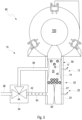
- Figure 3 depicts schematics of an air filter system 100 with a valve arrangement 80 in a first working phase for collecting dust particles 46 according to an embodiment of the invention
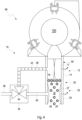
- Figure 4 depicts the air filter system 100 in a second working phase for scavenging the dust particles 46 from the air filter system 100.
- the embodiment shown in Figure 3 resembles the embodiments shown in Figures 1 and 2 , except that there is no connection component 20, because the two valves 12, 22 are directly connected in the interface region 52 without an additional connection component 20. This is due to simplification of the schematics in order to show the main functions of the valve arrangement 80 only.
- the valve control unit 34 comprises a two-way valve 44 for controlling the air flow 42 from the air supply system 36 to the chambers 17, 27 of the flexible membranes 14, 24 of the valves 12, 22 via air pipes 38, 40 respectively 36.
- the first valve 12 adjacent to the air filter system 100 is open, thus representing in its inner space the collection volume 30 for particulate matter 46 as e.g. dust, whereas the second valve 22 connected in series is closed by inflating the chamber 27 of the flexible membrane 24.
- the first valve 12 adjacent to the air filter system 100 is closed by inflating the chamber 17 of the corresponding membrane 14, whereas the second valve 22 is opened by deflating the chamber 27 of the flexible membrane 24.
- the particulate matter 46 from the collection volume 30 of the first valve 12 is transported, e.g. by gravity or by fluid pressure, from the first valve 12 to the second valve 22 and may exit through an outlet of the valve 22.
Landscapes
- Engineering & Computer Science (AREA)
- General Engineering & Computer Science (AREA)
- Mechanical Engineering (AREA)
- Chemical & Material Sciences (AREA)
- Combustion & Propulsion (AREA)
- Physics & Mathematics (AREA)
- Fluid Mechanics (AREA)
- Filtering Of Dispersed Particles In Gases (AREA)
- Multiple-Way Valves (AREA)
Description
- The invention relates to an air filter system comprising a multi-valve device for scavenging particulate dust, and a valve arrangement comprising a multi-valve device as well as a method for scavenging particulate dust from an air filter system.
-
US 2010/0229972 A1 discloses an inertially activated ejection valve providing an inertially activated effluent ejector, and particularly an inertially activated dust ejector for an air induction system of an internal combustion engine in a vibratory system generating vibration. The vibration can be that of the engine itself, or a driven component such as an eccentric rotary driven weight. The dust ejection valve can be provided at various places in the air induction system of the internal combustion engine and is provided between the pre-cleaner and the air filter. -
US 2010/0229972 A1 further discloses a method for ejecting dust from an air induction system of an internal combustion engine in a vibratory system generating vibration. The method includes providing a dust ejection valve including an inertial mass, and inertially activating and driving the inertial mass by vibration to discharge dust from the air induction system. The method further includes providing the inertial mass as a plunger, and inertially driving the plunger by the vibration to vibrate and oscillate to an amplitude along an axial oscillation axis. Further it includes translating and oscillating the plunger inertial mass along an axial travel stroke in a channel extending along the oscillation axis, providing the plunger inertial mass with at least one valve face, providing the channel with at least one valve seat, and engaging the valve face and the valve seat at one end of the travel stroke. - From CN 108 397 568 A a flexible valve is known comprising an upper valve body, a lower valve body and a membrane sleeve, wherein the membrane sleeve is provided with a material conveying channel. The two ends of the membrane sleeve are connected with the upper valve body and the lower valve body correspondingly and the upper valve body or/and the lower valve body is/and connected in an axially-rotatable manner. When the upper valve body or/and the lower valve body axially rotates, the membrane sleeve is driven to rotate and distort, and a sealing point is formed.
-
US 4 820 315 A displays a unique vacuum loader and process to remove, collect, and dispose asbestos, hazardous material, and other particulate matter under continuous negative pressure. During the vacuuming process, a top valve will remain open for a time period to fill the reservoir tube by about 50 percent. During this time period, a lower valve will remain shut. -
DE 10 2013 211550 A1 relates to a powder feeding device, in particular for coating powder. The powder feeding device comprises a control device which is provided for selectively operating a dense phase powder pump in a powder conveying operating mode or a flushing operating mode. A powder inlet valve and the powder outlet valve of the dense phase powder pump are configured in each case as a pneumatically actuable compression valve which can be closed when an actuating pressure is applied. -
US 2006/0168958 A1 proposes a supercharged internal combustion engine system wherein the supercharger assembly includes an ejector pump driven by high-pressure air for pumping intake air into engine combustion chamber. During periods of natural engine aspiration the ejector pump can be by-passed to reduce flow impedance. -
EP 2 960 483 A1 proposes a dust discharge valve with an outlet opening and the dust separated during operation at least partially collected in a dust collection area in front of the outlet opening. The dust discharge valve has a closing element which is arranged on the outlet opening so that it can be opened in the outlet direction, and which keeps the outlet opening closed by a closing force during engine operation. The dust discharge valve can also be opened and/or released in a controlled and/or automated manner by means of an opening and/or blowing device. - It is an object of the invention to provide an air filter system comprising a multi-valve device with a simple and robust operating performance for scavenging particulate dust, and comprising also a valve arrangement using said multi-valve device.
- A further object of the invention is to provide a method for scavenging particulate dust, from an air filter system with such a valve arrangement.
- One object of the invention is achieved by an air filter system comprising a multi-valve device for scavenging particulate dust from the air filter system, comprising at least a first valve and a second valve arranged in series along a fluid path, to establish a collection volume for the particulate matter, wherein the first valve and the second valve each comprise a housing segment and a flexible membrane arranged inside the housing segment, wherein in each valve the flexible membrane is configured to close or open the fluid path through the valve, wherein the first valve and the second valve are configured to be connectable to a valve control unit for activating the flexible membranes independently from each other.
- A further object of the invention is achieved by the air filter system with a valve arrangement comprising a multi-valve device, the multi-valve device having at least a first and a second valve, wherein a valve control unit is provided for activating flexible membranes of valves of the multi-valve device independently from each other, and comprising a two-way valve for supplying the first valve with air and for supplying the second valve with air either, wherein the two-way valve being particularly a solenoid valve.
- A further object of the invention is achieved by a method for scavenging particulate dust from an air filter system, where a valve arrangement is connected to an outlet for particulate matter of the air filter system, the valve arrangement comprising a multi-valve device, the multi-valve device having at least a first and a second valve, wherein a valve control unit is provided for activating flexible membranes of valves of the multi-valve device independently from each other, and comprising a two-way valve for supplying the first valve with air and for supplying the second valve with air either, wherein the two-way valve being particularly a solenoid valve, the method comprising the air filter system operating in a first working phase with the first valve being open and the second valve being closed by the activated second flexible membrane for collecting particulate matter in a collection volume for the particulate matter, and the air filter system operating in a second working phase with the first valve being closed by the activated second flexible membrane and the second valve being open for scavenging particulate matter from the collection volume for the particulate matter along a fluid path through a second connector.
- The dependent claims, the description and the drawings describe advantageous embodiments of the invention.
- According to a first aspect of the invention, an air filter system comprising a multi-valve device is proposed for scavenging particulate dust from the air filter system, comprising at least a first valve and a second valve arranged in series along a fluid path, to establish a collection volume for the particulate matter. The first valve and the second valve each comprise a housing segment and a flexible membrane arranged inside the housing segment. In each valve the flexible membrane is configured to close or open the fluid path through the valve. The first valve and the second valve are configured to be connectable to a valve control unit for activating the flexible membranes independently from each other.
- The inventive air filter system comprising a multi-valve device may advantageously be used for flow controlling along the fluid path for dust collecting and scavenging. According to a favorable embodiment the multi-valve device may comprise three subsystems. Two housing segments as bodies with a flexible membrane forming an inflatable chamber and a central connection component between the two housing segments. The central connection component keeps membranes on both sides in place and allows the fixation of an air admission system. The upper housing segment may comprise an inflatable pinch valve held with a clip connector. The clip connector may include an interface for air filter plugging. The lower housing segment may also comprise an inflatable membrane held by a clip connector. The air admission system may supply air pressure for inflating alternatively chambers of both membranes. When a chamber of a flexible membrane is supplied with air, the corresponding valve pipe is closed. By this way the inventive air filter system comprising a multi-valve device may be used to collect dust from an air filter. In a first working phase the first valve adjacent to the air filter system may be open, thus representing in its inner space the collection volume for particulate dust, whereas the second valve connected in series is closed by inflating the chamber of the flexible membrane. For scavenging the particulate dust from the system, in a second working phase the first valve adjacent to the air filter system may be closed by inflating the chamber of the corresponding membrane, whereas the second valve may be opened by deflating the chamber of the flexible membrane. Thus the particulate matter from the collection volume of the first valve is transported, e.g. by gravity or by fluid pressure, from the first valve to the second valve and may exit through an outlet of the valve.
- Alternatively the flexible membranes may be activated mechanically for closing and opening the corresponding valves.
- The flexible membranes may be manufactured from rubber material or other elastomers, which are resistant to dust and/or oil and may work in ambient temperatures from - 20°C to 140°C, which are temperatures usually required in the ambience of internal combustion engines. Typical dimensions may be in the range of a length of about 60 mm with an internal free diameter of about 30 to 40 mm. It is to be understood that the dimensions may vary depending on the actual application of the multi-valve device.
- The described air filter system comprising a multi-valve device may advantageously be used for heavy-duty tractors or construction machines. The device may be integrated at an air filter system in a vertical position or an angled position to a vertical direction. Connection to the air filter system may advantageously be achieved by a quick connector system.
- The multi-valve device is assembled from existing pinch valves for creating a dust collection volume and is used for dust pre-separation of an air filter. The flexible membranes of the pinch valves may be activated with pressure from a turbocharger when being integrated in an internal combustion engine.
- The inventive air filter system comprising a multi-valve device reduces the risk of having leakages when dust discharging from an air filter system, which may advantageously improve dust pre-separation efficiency. More over the proposed air filter system comprising a multi-valve device may be able to work with a two stages turbo-charged engine.
- According to the claimed embodiment of the air filter system comprising a multi-valve device, the first valve and/or the second valve are configured as a pinch valve. Pinch valves are commercially available in various dimensions, such that the multi-valve device may be assembled according to the dimensions of the air filter system where the multi-valve device is intended to collect and scavenge dust during operation of the air filter system. Such pinch valves are advantageously available also for robust working conditions and ambiences.
- According to the claimed embodiment of the air filter system comprising a multi-valve device, the flexible membranes of the first valve and the second valve are formed integrally, in particular wherein each of the flexible membranes may provide a separated inflatable and deflatable chamber between the respective membrane and housing segment. Thus the flexible membrane formed integrally may be manufactured at a lower price. Favorably sealing of the chambers of the flexible membrane to each other and against the ambience may be provided in a reliable way.
- According to an advantageous embodiment of the air filter system comprising a multi-valve device, a separation ring may be arranged in the collection volume for the particulate matter between the two membranes, being configured to secure the flexible membranes to an inner wall of the housing segments. Thus fixation of the flexible membrane in the multi-valve device as well as sealing of the two chambers working independently to each other may be provided in an efficient and reliable way.
- According to an advantageous embodiment of the air filter system comprising a multi-valve device, the housing segments of the first valve and the second valve may be formed integrally. In such an embodiment connection of the two valves may be facilitated. Further manufacturing of the multi-valve device may be achieved in an efficient and reliable manner. Sealing of the two valves to each other is intrinsically achieved.
- According to an advantageous embodiment of the air filter system comprising a multi-valve device, the first housing segment and the second housing segment may be joined by a connection component. Favorably the connection segment serves for connecting and sealing the two valves to each other. Thus assembling the multi-valve device may be achieved in a very efficient and flexible way. Further changing one of the valves in case of maintenance may also be facilitated in a favorable manner.
- According to an advantageous embodiment of the air filter system comprising a multi-valve device, the first valve may comprise a first connector arranged opposite to the second valve with respect to the fluid path and/or the second valve may comprise a second connector arranged opposite to the first valve with respect to the fluid path. The connectors may serve for easy integration of the multi-valve device to an air filter system as well as to a dust collection system. Advantageously quick connectors may be used for easy connection and flexible changing of the multi-valve device in case of maintenance of the system.
- According to an advantageous embodiment of the air filter system comprising a multi-valve device, the first connector may be configured to secure a section of the first flexible membrane and/or the second connector may be configured to secure a section of the second flexible membrane, and/or wherein an interface region between the first and second housing segments may be configured to secure a section of at least one of the flexible membranes. In such an embodiment the flexible membranes may easily be assembled to the housing segments of the valves. Further sealing of the flexible membranes against the housing segments and the ambience may be facilitated. Thus a robust design of the multi-valve device may be achieved.
- According to a further aspect of the invention, the air filter system with a valve arrangement is proposed comprising a multi-valve device. The multi-valve device has at least a first and a second valve. A valve control unit is provided for activating flexible membranes of valves of the multi-valve device independently from each other. The valve arrangement comprises a two-way valve for supplying the first valve with air and for supplying the second valve with air either. The two-way valve may particularly be a solenoid valve. The valve control unit together with the two-way valve may serve for activating the flexible membranes of the multi-valve device, thus controlling the functions of the scavenging an air filter system from particulate matter such as dust. By this way all advantages of the proposed multi-valve device described above may be achieved in a favorable manner.
- According to an advantageous embodiment, the flexible membranes may be controlled pneumatically by the valve control unit, in particular by air pressure. Pneumatic control of the flexible membranes is a very efficient and fast reaction means for opening and closing the valves of the multi-valve device. Further air pressure from turbo-chargers may favorably be used, if integrating the valve arrangement in an internal combustion engine, particularly in heavy duty engines of construction machines.
- According to an advantageous embodiment of the valve arrangement, the valve control unit may be fixed to the interface region, in particular wherein the valve control unit may be fixed to a connection component located at the interface region. Thus the valve control may easily be fixed to the multi-valve device for efficient assembling of the valve arrangement and easy maintenance. Further short distances between the valve control and the valves is advantageous for connecting air pipes from the valve control to the valves.
- According to a further aspect of the invention, a method is proposed for scavenging particulate dust from an air filter system. A valve arrangement is connected to an outlet for particulate matter of the air filter system. The valve arrangement comprises a multi-valve device, which has at least a first and a second valve. A valve control unit is provided for activating flexible membranes of valves of the multi-valve device independently from each other. The valve arrangement comprises a two-way valve for supplying the first valve with air and for supplying the second valve with air either. The two-way valve may particularly be a solenoid valve. The method comprises operating the air filter system in a first working phase with the first valve being open and the second valve being closed by the activated second flexible membrane for collecting particulate matter in a collection volume for the particulate matter, and operating the air filter system in a second working phase with the first valve being closed by the activated second flexible membrane and the second valve being open for scavenging particulate matter from the collection volume for the particulate matter along a fluid path through a second connector.
- The valve arrangement comprises a two-way valve for supplying the first valve with air and for supplying the second valve with air either. The two-way valve may particularly be a solenoid valve. The valve control unit together with the two-way valve may serve for activating the flexible membranes of the multi-valve device, thus controlling the functions of the scavenging an air filter system from particulate matter such as dust.
- The multi-valve device is used for flow controlling along the fluid path for dust collecting and scavenging. According to a favorable embodiment the air filter system comprising the multi-valve device may comprise three subsystems, i.e. two housing segments as bodies with a flexible membrane forming an inflatable chamber and a central connection component between the two housing segments. The central connection component keeps membranes on both sides in place and allows the fixation of an air admission system. The upper housing segment may comprise an inflatable pinch valve held with a clip connector. The clip connector may include an interface for air filter plugging. The lower housing segment may also comprise an inflatable membrane held by a clip connector. The air admission system may supply air pressure for inflating alternatively chambers of both membranes. When a chamber of a flexible membrane is supplied with air, the corresponding valve pipe is closed. By this way the inventive air filter system comprising a multi-valve device is used to collect dust from an air filter.
- In a first working phase the first valve adjacent to the air filter system may be open, thus representing in its inner space the collection volume for particulate dust, whereas the second valve connected in series is closed by inflating the chamber of the flexible membrane. For scavenging the particulate matter from the system, in a second working phase the first valve adjacent to the air filter system may be closed by inflating the chamber of the corresponding membrane, whereas the second valve may be opened by deflating the chamber of the flexible membrane. Thus the particulate matter from the collection volume of the first valve is transported, e.g. by gravity or by fluid pressure, from the first valve to the second valve and may exit through an outlet of the valve.
- The present invention together with the above-mentioned and other objects and advantages may best be understood from the following detailed description of the embodiments, but not restricted to the embodiments, wherein is shown in:
- Figure 1
- schematics of a valve arrangement with a multi-valve device according to an embodiment of the inventive air filter system;
- Figure 2
- schematics of a valve arrangement with a multi-valve device according to a further embodiment of the inventive air filter system;
- Figure 3
- schematics of an air filter system with a valve arrangement in a first working phase for collecting dust particles according to an embodiment of the invention; and
- Figure 4
- schematics of an air filter system with a valve arrangement in a second working phase for scavenging dust particles from the air filter system according to an embodiment of the invention.
- In the drawings, like elements are referred to with equal reference numerals. The drawings are merely schematic representations, not intended to portray specific parameters of the invention. Moreover, the drawings are intended to depict only typical embodiments of the invention and therefore should not be considered as limiting the scope of the invention.
-
Figure 1 depicts schematics of avalve arrangement 80 with amulti-valve device 10 according to an embodiment of the inventiveair filter system 100 for scavengingparticulate dust 46 from theair filter system 100. - The
valve arrangement 80 comprises themulti-valve device 10, consisting of a first and asecond valve valve control unit 34 as an air distributor system is provided for activatingflexible membranes valves multi-valve device 10 independently from each other. Thevalve control 34 comprises a two-way valve 44, depicted in the embodiments shown inFigures 3 and4 , for supplying thefirst valve 12 with air and for supplying thesecond valve 22 with air either viaair pipes way valve 44 being particularly a solenoid valve. - The
first valve 12 and thesecond valve 22 are configured as a pinch valve each. Thefirst valve 12 and thesecond valve 22 of themulti-valve device 10 are arranged in series along afluid path 32, to establish acollection volume 30 for theparticulate matter 46. Thefirst valve 12 and thesecond valve 22 each comprise ahousing segment flexible membrane housing segment deflatable chamber valve flexible membrane fluid path 32 through thevalve first valve 12 and thesecond valve 22 are connected to thevalve control unit 34 for activating theflexible membranes flexible membranes valve control unit 34, in particular by air pressure, being supplied by anair supply system 36. - The
first housing segment 14 and thesecond housing segment 24 are joined by aconnection component 20, thus forming a housing of themulti-valve device 10. Thevalve control unit 34 is fixed to theinterface region 52, in particular is thevalve control unit 34 fixed to theconnection component 20 located at theinterface region 52. - According to the invention, the
housing segments first valve 12 and thesecond valve 22 are formed integrally for easy assembly of themulti-valve device 10. - The
first valve 12 comprises afirst connector 18 arranged opposite to thesecond valve 22 with respect to thefluid path 32 and thesecond valve 22 comprises asecond connector 28 arranged opposite to thefirst valve 12 with respect to thefluid path 32. Themulti-valve device 10 is connected to adust outlet 102 of theair filter system 100 with thefirst connector 18. Thesecond connector 28 may serve for connecting themulti-valve device 10 to a dust collecting system. - The
first connector 18 is configured to secure asection 19 of the firstflexible membrane 16 and thesecond connector 28 is configured to secure asection 29 of the secondflexible membrane 26. Theinterface region 52 between the first andsecond housing segments section flexible membranes - Using the
valve arrangement 80 with theair filter system 100 depicted inFigure 1 allows to apply a method for scavengingparticulate matter 46, in particular dust, from theair filter system 100. In a first working phase thefirst valve 12 is open and thesecond valve 22 is closed by the activated secondflexible membrane 26 for collectingparticulate matter 46 in acollection volume 30 for theparticulate matter 46. In a second working phase thefirst valve 12 is closed by the activated secondflexible membrane 26 and thesecond valve 22 is open for scavengingparticulate matter 46 from thecollection volume 30 for theparticulate matter 46 along afluid path 32 through asecond connector 28. -
Figure 2 depicts schematics of avalve arrangement 80 with amulti-valve device 10 according to a further embodiment of the inventive air filter system. Themulti-valve device 10 of the embodiment shown inFigure 2 differs from the embodiment shown inFigure 1 by the fact, that theflexible membranes first valve 12 and thesecond valve 22 are formed integrally as a single piece. There still exist twomembrane sections second valve flexible membrane sections deflatable chamber respective membrane housing segment separation ring 54 is arranged in thecollection volume 30 for theparticulate matter 46 between the twomembranes separation ring 54 is configured to secure theflexible membranes membrane sections housing segments membranes membranes inflatable chambers -
Figure 3 depicts schematics of anair filter system 100 with avalve arrangement 80 in a first working phase for collectingdust particles 46 according to an embodiment of the invention, whereasFigure 4 depicts theair filter system 100 in a second working phase for scavenging thedust particles 46 from theair filter system 100. - The embodiment shown in
Figure 3 resembles the embodiments shown inFigures 1 and2 , except that there is noconnection component 20, because the twovalves interface region 52 without anadditional connection component 20. This is due to simplification of the schematics in order to show the main functions of thevalve arrangement 80 only. Thevalve control unit 34 comprises a two-way valve 44 for controlling theair flow 42 from theair supply system 36 to thechambers flexible membranes valves air pipes - In the first working phase the
first valve 12 adjacent to theair filter system 100 is open, thus representing in its inner space thecollection volume 30 forparticulate matter 46 as e.g. dust, whereas thesecond valve 22 connected in series is closed by inflating thechamber 27 of theflexible membrane 24. For scavenging theparticulate matter 46 from theair filter system 100, in the second working phase thefirst valve 12 adjacent to theair filter system 100 is closed by inflating thechamber 17 of the correspondingmembrane 14, whereas thesecond valve 22 is opened by deflating thechamber 27 of theflexible membrane 24. Thus theparticulate matter 46 from thecollection volume 30 of thefirst valve 12 is transported, e.g. by gravity or by fluid pressure, from thefirst valve 12 to thesecond valve 22 and may exit through an outlet of thevalve 22.
Claims (10)
- An air filter system (100) comprising a multi-valve device (10) for scavenging particulate dust (46) from said air filter system (100) comprising at least a first valve (12) and a second valve (22) arranged in series along a fluid path (32), to establish a collection volume (30) for the particulate matter (46), wherein the first valve (12) and the second valve (22) each comprise a housing segment (14, 24) and a flexible membrane (16, 26) arranged inside the housing segment (14, 24), wherein in each valve (12, 22) the flexible membrane (16, 26) is configured to close or open the fluid path (32) through the valve (12, 22), wherein the first valve (12) and the second valve (22) are configured to be connectable to a valve control unit (34) for activating the flexible membranes (16, 26) independently from each other, wherein the first valve (12) and the second valve (22) being configured as a pinch valve, wherein the flexible membranes (16, 26) of the first valve (12) and the second valve (22) are formed integrally, in particular wherein each of the flexible membranes (16, 26) provide a separated inflatable and deflatable chamber (17, 27) between the respective membrane (16, 26) and housing segment (14, 24).
- The air filter system (100) according to claim 1, wherein a separation ring (54) is arranged in the collection volume (30) for the particulate matter (46) between the two membranes (16, 26), being configured to secure the flexible membranes (16, 26) to an inner wall of the housing segments (14, 24).
- The air filter system (100) according to any one of the preceding claims, wherein the housing segments (14, 24) of the first valve (12) and the second valve (22) are formed integrally.
- The air filter system (100) according to one of the claims 1 or 2, wherein the first housing segment (14) and the second housing segment (24) are joined by a connection component (20).
- The air filter system (100) according to any one of the preceding claims, wherein the first valve (12) comprises a first connector (18) arranged opposite to the second valve (22) with respect to the fluid path (32) and/or the second valve (22) comprises a second connector (28) arranged opposite to the first valve (12) with respect to the fluid path (32).
- The air filter system (100) according to claim 5, wherein the first connector (18) is configured to secure a section (19) of the first flexible membrane (16) and/or the second connector (28) is configured to secure a section (29) of the second flexible membrane (26), and/or wherein an interface region (52) between the first and second housing segments (14, 24) is configured to secure a section (15, 25) of at least one of the flexible membranes (16, 26).
- The air filter system (100) according to any one of the preceding claims, with a valve arrangement (80) comprising the multi valve device (10), the multi-valve device (10) having at least a first and a second valve (12, 22), wherein a valve control unit (34) is provided for activating flexible membranes (16, 26) of valves (12, 22) of the multi-valve device (10) independently from each other, and comprising a two-way valve (44) for supplying the first valve (12) with air and for supplying the second valve (22) with air either, wherein the two-way valve (44) being particularly a solenoid valve.
- The air filter system (100) according to claim 7, wherein the flexible membranes (16, 26) are controlled pneumatically by the valve control unit (34), in particular by air pressure.
- The air filter system (100) according to claim 7 or 8 comprising the air filter system according to claim 6, wherein the valve control unit (34) is fixed to the interface region (52), in particular wherein the valve control unit (34) is fixed to a connection component (20) located at the interface region (52).
- A method for scavenging particulate dust (46) from an air filter system (100) according to the claims 67 to 9, where the valve arrangement (80) is connected to an outlet (102) for particulate dust (46) of the air filter system (100), the multi-valve device (10) having at least a first and a second valve (12, 22), wherein a valve control unit (34) is provided for activating flexible membranes (16, 26) of valves (12, 22) of the multi-valve device (10) independently from each other, and comprising a two-way valve (44) for supplying the first valve (12) with air and for supplying the second valve (22) with air either, wherein the two-way valve (44) being particularly a solenoid valve,
the method comprising- operating the air filter system (100) in a first working phase with the first valve (12) being open and the second valve (22) being closed by the activated second flexible membrane (26) for collecting particulate matter (46) in a collection volume (30) for the particulate matter (46),- operating the air filter system (100) in a second working phase with the first valve (12) being closed by the activated second flexible membrane (26) and the second valve (22) being open for scavenging particulate matter (46) from the collection volume (30) for the particulate matter (46) along a fluid path (32) through a second connector (28).
Priority Applications (2)
| Application Number | Priority Date | Filing Date | Title |
|---|---|---|---|
| EP19290017.3A EP3712419B1 (en) | 2019-03-19 | 2019-03-19 | Multi-valve device and valve arrangement |
| PCT/EP2020/057134 WO2020187844A1 (en) | 2019-03-19 | 2020-03-16 | Multi-valve device and valve arrangement |
Applications Claiming Priority (1)
| Application Number | Priority Date | Filing Date | Title |
|---|---|---|---|
| EP19290017.3A EP3712419B1 (en) | 2019-03-19 | 2019-03-19 | Multi-valve device and valve arrangement |
Publications (2)
| Publication Number | Publication Date |
|---|---|
| EP3712419A1 EP3712419A1 (en) | 2020-09-23 |
| EP3712419B1 true EP3712419B1 (en) | 2024-12-11 |
Family
ID=66102011
Family Applications (1)
| Application Number | Title | Priority Date | Filing Date |
|---|---|---|---|
| EP19290017.3A Active EP3712419B1 (en) | 2019-03-19 | 2019-03-19 | Multi-valve device and valve arrangement |
Country Status (2)
| Country | Link |
|---|---|
| EP (1) | EP3712419B1 (en) |
| WO (1) | WO2020187844A1 (en) |
Family Cites Families (9)
| Publication number | Priority date | Publication date | Assignee | Title |
|---|---|---|---|---|
| US4820315A (en) * | 1987-11-27 | 1989-04-11 | Demarco Thomas M | Vacuum loader and process for removing asbestos and other particulate material |
| US5186431A (en) * | 1989-09-22 | 1993-02-16 | Yehuda Tamari | Pressure sensitive valves for extracorporeal circuits |
| DE10131021A1 (en) * | 2001-06-27 | 2003-01-09 | Mann & Hummel Filter | Venting valve for crankcase I IC engine has a tubular housing with tubular membrane in a venturi design |
| US20060168958A1 (en) * | 2005-01-02 | 2006-08-03 | Jan Vetrovec | Supercharged internal combustion engine |
| DE102005020442B4 (en) * | 2005-04-29 | 2018-01-25 | Mahle International Gmbh | Venting device for a crankcase of an internal combustion engine |
| US8074672B2 (en) | 2009-03-12 | 2011-12-13 | Cummins Filtration Ip, Inc. | Inertially activated ejection valve |
| DE102013211550A1 (en) * | 2013-06-19 | 2014-12-24 | Gema Switzerland Gmbh | Powder conveying device, in particular for coating powder |
| DE102014009417A1 (en) * | 2014-06-24 | 2015-12-24 | Man Truck & Bus Ag | Apparatus for separating dust in the unfiltered air region of the engine air intake of a vehicle, in particular a commercial vehicle |
| CN108397568A (en) * | 2018-06-05 | 2018-08-14 | 陈重 | A kind of elastomeric valves |
-
2019
- 2019-03-19 EP EP19290017.3A patent/EP3712419B1/en active Active
-
2020
- 2020-03-16 WO PCT/EP2020/057134 patent/WO2020187844A1/en not_active Ceased
Also Published As
| Publication number | Publication date |
|---|---|
| EP3712419A1 (en) | 2020-09-23 |
| WO2020187844A1 (en) | 2020-09-24 |
Similar Documents
| Publication | Publication Date | Title |
|---|---|---|
| EP1214513B1 (en) | Device for the transfer of exhaust gas from the exhaust collector of a supercharged internal combustion engine to the inlet conduit thereof | |
| CA1234022A (en) | Actuator valve | |
| US4530210A (en) | Apparatus for controlling evaporated fuel in an internal combustion engine having a supercharger | |
| EP3186123B1 (en) | Low-cost evacuator for an engine having tuned venturi gaps | |
| JP2009533598A (en) | Improved vacuum pump | |
| CN102822522B (en) | Air Motors with Ceramic Valves | |
| CN108223197B (en) | Evaporated fuel treatment device for internal combustion engine | |
| US9145824B2 (en) | Pneumatic compressor recirculation valve system for minimizing surge under boost during throttle closing | |
| KR20170102868A (en) | Crankcase ventilating evacuator | |
| CA2615341A1 (en) | Combustion powered fastener-driving tool with interconnected chambers | |
| WO2012128957A2 (en) | Actuator shaft boot | |
| CN101313135B (en) | Internal combustion engine having two turbocharging systems | |
| EP1094215A3 (en) | Acceleration device for a two-cycle engine | |
| CA2416042E (en) | Gas compressor and method with an improved inlet and discharge valve arrangement | |
| EP3712419B1 (en) | Multi-valve device and valve arrangement | |
| US6170444B1 (en) | Air and exhaust gas management system for a two-cycle internal combustion engine | |
| US8287249B2 (en) | Two-stage membrane pump with economical inlet port design | |
| CN107228061B (en) | Air compressor of body cooling integration | |
| CN204042153U (en) | Actuator | |
| CN207715327U (en) | A kind of compressor and the mechanized equipment with the compressor | |
| CN101096926A (en) | Height above sea level compensation of turbo-charger exhaust valve | |
| CN107237731B (en) | Single-cylinder single-piston two-stage air compressor | |
| CN117441062A (en) | Piston compressors, especially radial piston compressors | |
| CN208982283U (en) | Small screw integrated machine integrated device | |
| US20070193797A1 (en) | Pressure booster system |
Legal Events
| Date | Code | Title | Description |
|---|---|---|---|
| STAA | Information on the status of an ep patent application or granted ep patent |
Free format text: STATUS: UNKNOWN |
|
| PUAI | Public reference made under article 153(3) epc to a published international application that has entered the european phase |
Free format text: ORIGINAL CODE: 0009012 |
|
| STAA | Information on the status of an ep patent application or granted ep patent |
Free format text: STATUS: THE APPLICATION HAS BEEN PUBLISHED |
|
| AK | Designated contracting states |
Kind code of ref document: A1 Designated state(s): AL AT BE BG CH CY CZ DE DK EE ES FI FR GB GR HR HU IE IS IT LI LT LU LV MC MK MT NL NO PL PT RO RS SE SI SK SM TR |
|
| AX | Request for extension of the european patent |
Extension state: BA ME |
|
| STAA | Information on the status of an ep patent application or granted ep patent |
Free format text: STATUS: REQUEST FOR EXAMINATION WAS MADE |
|
| 17P | Request for examination filed |
Effective date: 20210305 |
|
| RBV | Designated contracting states (corrected) |
Designated state(s): AL AT BE BG CH CY CZ DE DK EE ES FI FR GB GR HR HU IE IS IT LI LT LU LV MC MK MT NL NO PL PT RO RS SE SI SK SM TR |
|
| RAP3 | Party data changed (applicant data changed or rights of an application transferred) |
Owner name: MANN+HUMMEL GMBH |
|
| STAA | Information on the status of an ep patent application or granted ep patent |
Free format text: STATUS: EXAMINATION IS IN PROGRESS |
|
| 17Q | First examination report despatched |
Effective date: 20221025 |
|
| GRAP | Despatch of communication of intention to grant a patent |
Free format text: ORIGINAL CODE: EPIDOSNIGR1 |
|
| STAA | Information on the status of an ep patent application or granted ep patent |
Free format text: STATUS: GRANT OF PATENT IS INTENDED |
|
| INTG | Intention to grant announced |
Effective date: 20240215 |
|
| GRAJ | Information related to disapproval of communication of intention to grant by the applicant or resumption of examination proceedings by the epo deleted |
Free format text: ORIGINAL CODE: EPIDOSDIGR1 |
|
| STAA | Information on the status of an ep patent application or granted ep patent |
Free format text: STATUS: EXAMINATION IS IN PROGRESS |
|
| INTC | Intention to grant announced (deleted) | ||
| GRAP | Despatch of communication of intention to grant a patent |
Free format text: ORIGINAL CODE: EPIDOSNIGR1 |
|
| STAA | Information on the status of an ep patent application or granted ep patent |
Free format text: STATUS: GRANT OF PATENT IS INTENDED |
|
| INTG | Intention to grant announced |
Effective date: 20240731 |
|
| GRAS | Grant fee paid |
Free format text: ORIGINAL CODE: EPIDOSNIGR3 |
|
| GRAA | (expected) grant |
Free format text: ORIGINAL CODE: 0009210 |
|
| STAA | Information on the status of an ep patent application or granted ep patent |
Free format text: STATUS: THE PATENT HAS BEEN GRANTED |
|
| AK | Designated contracting states |
Kind code of ref document: B1 Designated state(s): AL AT BE BG CH CY CZ DE DK EE ES FI FR GB GR HR HU IE IS IT LI LT LU LV MC MK MT NL NO PL PT RO RS SE SI SK SM TR |
|
| REG | Reference to a national code |
Ref country code: GB Ref legal event code: FG4D |
|
| RIN1 | Information on inventor provided before grant (corrected) |
Inventor name: SARRAZIN, MAXIME Inventor name: ZENNER, JULIEN Inventor name: MIGAUD, JEROME |
|
| REG | Reference to a national code |
Ref country code: CH Ref legal event code: EP |
|
| REG | Reference to a national code |
Ref country code: IE Ref legal event code: FG4D |
|
| REG | Reference to a national code |
Ref country code: DE Ref legal event code: R096 Ref document number: 602019063318 Country of ref document: DE |
|
| P01 | Opt-out of the competence of the unified patent court (upc) registered |
Free format text: CASE NUMBER: APP_63469/2024 Effective date: 20241129 |
|
| REG | Reference to a national code |
Ref country code: LT Ref legal event code: MG9D |
|
| PG25 | Lapsed in a contracting state [announced via postgrant information from national office to epo] |
Ref country code: HR Free format text: LAPSE BECAUSE OF FAILURE TO SUBMIT A TRANSLATION OF THE DESCRIPTION OR TO PAY THE FEE WITHIN THE PRESCRIBED TIME-LIMIT Effective date: 20241211 |
|
| PG25 | Lapsed in a contracting state [announced via postgrant information from national office to epo] |
Ref country code: FI Free format text: LAPSE BECAUSE OF FAILURE TO SUBMIT A TRANSLATION OF THE DESCRIPTION OR TO PAY THE FEE WITHIN THE PRESCRIBED TIME-LIMIT Effective date: 20241211 |
|
| PG25 | Lapsed in a contracting state [announced via postgrant information from national office to epo] |
Ref country code: BG Free format text: LAPSE BECAUSE OF FAILURE TO SUBMIT A TRANSLATION OF THE DESCRIPTION OR TO PAY THE FEE WITHIN THE PRESCRIBED TIME-LIMIT Effective date: 20241211 |
|
| REG | Reference to a national code |
Ref country code: NL Ref legal event code: MP Effective date: 20241211 |
|
| PG25 | Lapsed in a contracting state [announced via postgrant information from national office to epo] |
Ref country code: ES Free format text: LAPSE BECAUSE OF FAILURE TO SUBMIT A TRANSLATION OF THE DESCRIPTION OR TO PAY THE FEE WITHIN THE PRESCRIBED TIME-LIMIT Effective date: 20241211 |
|
| PG25 | Lapsed in a contracting state [announced via postgrant information from national office to epo] |
Ref country code: NO Free format text: LAPSE BECAUSE OF FAILURE TO SUBMIT A TRANSLATION OF THE DESCRIPTION OR TO PAY THE FEE WITHIN THE PRESCRIBED TIME-LIMIT Effective date: 20250311 |
|
| PG25 | Lapsed in a contracting state [announced via postgrant information from national office to epo] |
Ref country code: GR Free format text: LAPSE BECAUSE OF FAILURE TO SUBMIT A TRANSLATION OF THE DESCRIPTION OR TO PAY THE FEE WITHIN THE PRESCRIBED TIME-LIMIT Effective date: 20250312 Ref country code: LV Free format text: LAPSE BECAUSE OF FAILURE TO SUBMIT A TRANSLATION OF THE DESCRIPTION OR TO PAY THE FEE WITHIN THE PRESCRIBED TIME-LIMIT Effective date: 20241211 |
|
| PG25 | Lapsed in a contracting state [announced via postgrant information from national office to epo] |
Ref country code: RS Free format text: LAPSE BECAUSE OF FAILURE TO SUBMIT A TRANSLATION OF THE DESCRIPTION OR TO PAY THE FEE WITHIN THE PRESCRIBED TIME-LIMIT Effective date: 20250311 |
|
| PG25 | Lapsed in a contracting state [announced via postgrant information from national office to epo] |
Ref country code: NL Free format text: LAPSE BECAUSE OF FAILURE TO SUBMIT A TRANSLATION OF THE DESCRIPTION OR TO PAY THE FEE WITHIN THE PRESCRIBED TIME-LIMIT Effective date: 20241211 |
|
| REG | Reference to a national code |
Ref country code: AT Ref legal event code: MK05 Ref document number: 1750547 Country of ref document: AT Kind code of ref document: T Effective date: 20241211 |
|
| PG25 | Lapsed in a contracting state [announced via postgrant information from national office to epo] |
Ref country code: SM Free format text: LAPSE BECAUSE OF FAILURE TO SUBMIT A TRANSLATION OF THE DESCRIPTION OR TO PAY THE FEE WITHIN THE PRESCRIBED TIME-LIMIT Effective date: 20241211 |
|
| PG25 | Lapsed in a contracting state [announced via postgrant information from national office to epo] |
Ref country code: PL Free format text: LAPSE BECAUSE OF FAILURE TO SUBMIT A TRANSLATION OF THE DESCRIPTION OR TO PAY THE FEE WITHIN THE PRESCRIBED TIME-LIMIT Effective date: 20241211 |
|
| PG25 | Lapsed in a contracting state [announced via postgrant information from national office to epo] |
Ref country code: IS Free format text: LAPSE BECAUSE OF FAILURE TO SUBMIT A TRANSLATION OF THE DESCRIPTION OR TO PAY THE FEE WITHIN THE PRESCRIBED TIME-LIMIT Effective date: 20250411 |
|
| PG25 | Lapsed in a contracting state [announced via postgrant information from national office to epo] |
Ref country code: PT Free format text: LAPSE BECAUSE OF FAILURE TO SUBMIT A TRANSLATION OF THE DESCRIPTION OR TO PAY THE FEE WITHIN THE PRESCRIBED TIME-LIMIT Effective date: 20250411 |
|
| PG25 | Lapsed in a contracting state [announced via postgrant information from national office to epo] |
Ref country code: EE Free format text: LAPSE BECAUSE OF FAILURE TO SUBMIT A TRANSLATION OF THE DESCRIPTION OR TO PAY THE FEE WITHIN THE PRESCRIBED TIME-LIMIT Effective date: 20241211 |
|
| PG25 | Lapsed in a contracting state [announced via postgrant information from national office to epo] |
Ref country code: AT Free format text: LAPSE BECAUSE OF FAILURE TO SUBMIT A TRANSLATION OF THE DESCRIPTION OR TO PAY THE FEE WITHIN THE PRESCRIBED TIME-LIMIT Effective date: 20241211 Ref country code: RO Free format text: LAPSE BECAUSE OF FAILURE TO SUBMIT A TRANSLATION OF THE DESCRIPTION OR TO PAY THE FEE WITHIN THE PRESCRIBED TIME-LIMIT Effective date: 20241211 |
|
| PG25 | Lapsed in a contracting state [announced via postgrant information from national office to epo] |
Ref country code: SK Free format text: LAPSE BECAUSE OF FAILURE TO SUBMIT A TRANSLATION OF THE DESCRIPTION OR TO PAY THE FEE WITHIN THE PRESCRIBED TIME-LIMIT Effective date: 20241211 |
|
| PG25 | Lapsed in a contracting state [announced via postgrant information from national office to epo] |
Ref country code: CZ Free format text: LAPSE BECAUSE OF FAILURE TO SUBMIT A TRANSLATION OF THE DESCRIPTION OR TO PAY THE FEE WITHIN THE PRESCRIBED TIME-LIMIT Effective date: 20241211 |
|
| PG25 | Lapsed in a contracting state [announced via postgrant information from national office to epo] |
Ref country code: IT Free format text: LAPSE BECAUSE OF FAILURE TO SUBMIT A TRANSLATION OF THE DESCRIPTION OR TO PAY THE FEE WITHIN THE PRESCRIBED TIME-LIMIT Effective date: 20241211 |
|
| PG25 | Lapsed in a contracting state [announced via postgrant information from national office to epo] |
Ref country code: SE Free format text: LAPSE BECAUSE OF FAILURE TO SUBMIT A TRANSLATION OF THE DESCRIPTION OR TO PAY THE FEE WITHIN THE PRESCRIBED TIME-LIMIT Effective date: 20241211 |
|
| REG | Reference to a national code |
Ref country code: DE Ref legal event code: R097 Ref document number: 602019063318 Country of ref document: DE |
|
| PG25 | Lapsed in a contracting state [announced via postgrant information from national office to epo] |
Ref country code: DK Free format text: LAPSE BECAUSE OF FAILURE TO SUBMIT A TRANSLATION OF THE DESCRIPTION OR TO PAY THE FEE WITHIN THE PRESCRIBED TIME-LIMIT Effective date: 20241211 |
|
| PG25 | Lapsed in a contracting state [announced via postgrant information from national office to epo] |
Ref country code: MC Free format text: LAPSE BECAUSE OF FAILURE TO SUBMIT A TRANSLATION OF THE DESCRIPTION OR TO PAY THE FEE WITHIN THE PRESCRIBED TIME-LIMIT Effective date: 20241211 |
|
| PLBE | No opposition filed within time limit |
Free format text: ORIGINAL CODE: 0009261 |
|
| STAA | Information on the status of an ep patent application or granted ep patent |
Free format text: STATUS: NO OPPOSITION FILED WITHIN TIME LIMIT |
|
| REG | Reference to a national code |
Ref country code: CH Ref legal event code: L10 Free format text: ST27 STATUS EVENT CODE: U-0-0-L10-L00 (AS PROVIDED BY THE NATIONAL OFFICE) Effective date: 20251022 |
|
| REG | Reference to a national code |
Ref country code: CH Ref legal event code: H13 Free format text: ST27 STATUS EVENT CODE: U-0-0-H10-H13 (AS PROVIDED BY THE NATIONAL OFFICE) Effective date: 20251024 |
|
| PG25 | Lapsed in a contracting state [announced via postgrant information from national office to epo] |
Ref country code: LU Free format text: LAPSE BECAUSE OF NON-PAYMENT OF DUE FEES Effective date: 20250319 |
|
| 26N | No opposition filed |
Effective date: 20250912 |
|
| GBPC | Gb: european patent ceased through non-payment of renewal fee |
Effective date: 20250319 |
|
| REG | Reference to a national code |
Ref country code: BE Ref legal event code: MM Effective date: 20250331 |
|
| PG25 | Lapsed in a contracting state [announced via postgrant information from national office to epo] |
Ref country code: GB Free format text: LAPSE BECAUSE OF NON-PAYMENT OF DUE FEES Effective date: 20250319 |
|
| PG25 | Lapsed in a contracting state [announced via postgrant information from national office to epo] |
Ref country code: FR Free format text: LAPSE BECAUSE OF NON-PAYMENT OF DUE FEES Effective date: 20250331 |
|
| PG25 | Lapsed in a contracting state [announced via postgrant information from national office to epo] |
Ref country code: BE Free format text: LAPSE BECAUSE OF NON-PAYMENT OF DUE FEES Effective date: 20250331 |
|
| PG25 | Lapsed in a contracting state [announced via postgrant information from national office to epo] |
Ref country code: CH Free format text: LAPSE BECAUSE OF NON-PAYMENT OF DUE FEES Effective date: 20250331 |
|
| PG25 | Lapsed in a contracting state [announced via postgrant information from national office to epo] |
Ref country code: IE Free format text: LAPSE BECAUSE OF NON-PAYMENT OF DUE FEES Effective date: 20250319 |
|
| PGFP | Annual fee paid to national office [announced via postgrant information from national office to epo] |
Ref country code: DE Payment date: 20260319 Year of fee payment: 8 |