EP3712418A1 - Method for operating a pressure control valve, method for operating a fluid supply system and device for operating a fluid supply system - Google Patents
Method for operating a pressure control valve, method for operating a fluid supply system and device for operating a fluid supply system Download PDFInfo
- Publication number
- EP3712418A1 EP3712418A1 EP19164188.5A EP19164188A EP3712418A1 EP 3712418 A1 EP3712418 A1 EP 3712418A1 EP 19164188 A EP19164188 A EP 19164188A EP 3712418 A1 EP3712418 A1 EP 3712418A1
- Authority
- EP
- European Patent Office
- Prior art keywords
- frequency
- valve
- pressure
- opening
- supply system
- Prior art date
- Legal status (The legal status is an assumption and is not a legal conclusion. Google has not performed a legal analysis and makes no representation as to the accuracy of the status listed.)
- Granted
Links
Images
Classifications
-
- F—MECHANICAL ENGINEERING; LIGHTING; HEATING; WEAPONS; BLASTING
- F02—COMBUSTION ENGINES; HOT-GAS OR COMBUSTION-PRODUCT ENGINE PLANTS
- F02D—CONTROLLING COMBUSTION ENGINES
- F02D41/00—Electrical control of supply of combustible mixture or its constituents
- F02D41/20—Output circuits, e.g. for controlling currents in command coils
-
- F—MECHANICAL ENGINEERING; LIGHTING; HEATING; WEAPONS; BLASTING
- F02—COMBUSTION ENGINES; HOT-GAS OR COMBUSTION-PRODUCT ENGINE PLANTS
- F02D—CONTROLLING COMBUSTION ENGINES
- F02D41/00—Electrical control of supply of combustible mixture or its constituents
- F02D41/30—Controlling fuel injection
- F02D41/38—Controlling fuel injection of the high pressure type
- F02D41/3809—Common rail control systems
- F02D41/3836—Controlling the fuel pressure
- F02D41/3863—Controlling the fuel pressure by controlling the flow out of the common rail, e.g. using pressure relief valves
-
- F—MECHANICAL ENGINEERING; LIGHTING; HEATING; WEAPONS; BLASTING
- F02—COMBUSTION ENGINES; HOT-GAS OR COMBUSTION-PRODUCT ENGINE PLANTS
- F02M—SUPPLYING COMBUSTION ENGINES IN GENERAL WITH COMBUSTIBLE MIXTURES OR CONSTITUENTS THEREOF
- F02M63/00—Other fuel-injection apparatus having pertinent characteristics not provided for in groups F02M39/00 - F02M57/00 or F02M67/00; Details, component parts, or accessories of fuel-injection apparatus, not provided for in, or of interest apart from, the apparatus of groups F02M39/00 - F02M61/00 or F02M67/00; Combination of fuel pump with other devices, e.g. lubricating oil pump
- F02M63/02—Fuel-injection apparatus having several injectors fed by a common pumping element, or having several pumping elements feeding a common injector; Fuel-injection apparatus having provisions for cutting-out pumps, pumping elements, or injectors; Fuel-injection apparatus having provisions for variably interconnecting pumping elements and injectors alternatively
- F02M63/0225—Fuel-injection apparatus having a common rail feeding several injectors ; Means for varying pressure in common rails; Pumps feeding common rails
- F02M63/023—Means for varying pressure in common rails
- F02M63/0235—Means for varying pressure in common rails by bleeding fuel pressure
- F02M63/025—Means for varying pressure in common rails by bleeding fuel pressure from the common rail
-
- F—MECHANICAL ENGINEERING; LIGHTING; HEATING; WEAPONS; BLASTING
- F02—COMBUSTION ENGINES; HOT-GAS OR COMBUSTION-PRODUCT ENGINE PLANTS
- F02D—CONTROLLING COMBUSTION ENGINES
- F02D41/00—Electrical control of supply of combustible mixture or its constituents
- F02D41/20—Output circuits, e.g. for controlling currents in command coils
- F02D2041/202—Output circuits, e.g. for controlling currents in command coils characterised by the control of the circuit
- F02D2041/2024—Output circuits, e.g. for controlling currents in command coils characterised by the control of the circuit the control switching a load after time-on and time-off pulses
-
- F—MECHANICAL ENGINEERING; LIGHTING; HEATING; WEAPONS; BLASTING
- F02—COMBUSTION ENGINES; HOT-GAS OR COMBUSTION-PRODUCT ENGINE PLANTS
- F02D—CONTROLLING COMBUSTION ENGINES
- F02D41/00—Electrical control of supply of combustible mixture or its constituents
- F02D41/20—Output circuits, e.g. for controlling currents in command coils
- F02D2041/202—Output circuits, e.g. for controlling currents in command coils characterised by the control of the circuit
- F02D2041/2055—Output circuits, e.g. for controlling currents in command coils characterised by the control of the circuit with means for determining actual opening or closing time
-
- F—MECHANICAL ENGINEERING; LIGHTING; HEATING; WEAPONS; BLASTING
- F02—COMBUSTION ENGINES; HOT-GAS OR COMBUSTION-PRODUCT ENGINE PLANTS
- F02D—CONTROLLING COMBUSTION ENGINES
- F02D41/00—Electrical control of supply of combustible mixture or its constituents
- F02D41/20—Output circuits, e.g. for controlling currents in command coils
- F02D2041/202—Output circuits, e.g. for controlling currents in command coils characterised by the control of the circuit
- F02D2041/2058—Output circuits, e.g. for controlling currents in command coils characterised by the control of the circuit using information of the actual current value
-
- F—MECHANICAL ENGINEERING; LIGHTING; HEATING; WEAPONS; BLASTING
- F02—COMBUSTION ENGINES; HOT-GAS OR COMBUSTION-PRODUCT ENGINE PLANTS
- F02D—CONTROLLING COMBUSTION ENGINES
- F02D41/00—Electrical control of supply of combustible mixture or its constituents
- F02D41/22—Safety or indicating devices for abnormal conditions
- F02D41/222—Safety or indicating devices for abnormal conditions relating to the failure of sensors or parameter detection devices
- F02D2041/223—Diagnosis of fuel pressure sensors
-
- F—MECHANICAL ENGINEERING; LIGHTING; HEATING; WEAPONS; BLASTING
- F02—COMBUSTION ENGINES; HOT-GAS OR COMBUSTION-PRODUCT ENGINE PLANTS
- F02M—SUPPLYING COMBUSTION ENGINES IN GENERAL WITH COMBUSTIBLE MIXTURES OR CONSTITUENTS THEREOF
- F02M63/00—Other fuel-injection apparatus having pertinent characteristics not provided for in groups F02M39/00 - F02M57/00 or F02M67/00; Details, component parts, or accessories of fuel-injection apparatus, not provided for in, or of interest apart from, the apparatus of groups F02M39/00 - F02M61/00 or F02M67/00; Combination of fuel pump with other devices, e.g. lubricating oil pump
- F02M63/0012—Valves
- F02M63/0031—Valves characterized by the type of valves, e.g. special valve member details, valve seat details, valve housing details
- F02M63/005—Pressure relief valves
- F02M63/0052—Pressure relief valves with means for adjusting the opening pressure, e.g. electrically controlled
Definitions
- the disclosure relates to a method for operating a pressure control valve of a fluid supply system for a vehicle.
- the disclosure further relates to a method for operating a fluid supply system for a vehicle, in particular for a fluid supply system with a pressure control valve.
- the disclosure further relates to a corresponding device for operating a fluid supply system for a vehicle.
- Fluid supply systems for diesel engines or gasoline engines may work with high pressure.
- So-called common rail direct fuel injection systems comprise a high pressure pump for feeding a common fuel rail.
- pressure in the rail is determined with the aid of a pressure sensor.
- the pump feeds fuel to the common rail dependent on a desired pressure and the signal of the pressure sensor.
- Exemplary embodiments herein provide a method for operating a pressure control valve of a fluid supply system for a vehicle.
- the method comprises: operating a pressure control valve of a fluid supply system for a vehicle, comprising:
- the method allows to use the pressure control valve as an indicator of the given opening pressure of the valve being exceeded.
- the given opening pressure equals a maximum system pressure of the fluid supply system.
- the opening pressure of the valve may be slightly higher than the maximum system pressure. If the valve opens, the system pressure is higher than the opening pressure of the valve. Due to the detection of the frequency change in the control signal, the opening of the valve is easy and reliable to detect.
- the change in the frequency of the control system results from a movement of an armature of the pressure control valve from a closed state to the open state. For example, the change in the frequency is due to the pole distance variation during opening and closing of the valve and the voltage induced due to the movement of the armature.
- the frequency change indicates the opening of the pressure control valve which also means that the rail pressure is above the opening pressure of the pressure control valve.
- This information can be used to indicate that the supply system has an overpressure. A corresponding failure reaction is possible to prevent a system burst. Thus, an overpressure can be avoided even if there is a malfunction of the rail pressure sensor. If the rail pressure sensor delivers a faulty signal, e.g. a stack signal, the overpressure in the system may not be determined depending on the signal of the rail pressure sensor. By detecting the frequency change of the control signal of the pressure control valve damage to the system due to overpressure can still be avoided.
- the second period follows directly after the first period.
- a relative change in the signal is detectable. Therefore other influencing factors like temperature can be disregarded.
- the opening of the valve is detected if the second frequency is greater than the first frequency depending on the movement of the armature and/or the pole piece of the valve relative to a coil of the valve. According to further embodiments, the opening of the valve is detected if the second frequency is smaller than the first frequency depending on the movement of the armature and/or the pole piece of the valve relative to a coil of the valve.
- the movement of the armature and/or the pole piece has an effect on the signal applied to the pressure control valve.
- the pole distance has an effect on the signal applied to the pressure control valve.
- the transition from closed to open has an effect on the current applied on the pressure control valve due to the movement of the armature.
- the transition from closed to open has an effect on the frequency with which the intensity of the current changes.
- the frequency is higher or lower when the pressure control valve opens dependent on the design of pressure control valve itself.
- a frequency increase or a frequency decrease can be detected depending on the design of the pressure control valve.
- the frequency change is detectable when the current of the pressure control valve is controlled via a current close loop control.
- the frequency change is due to the change of current gradient which is in particular based on the combination of two physical event: a current induction due to the movement of the anchor and an inductivity change due to a change in the pole distance (air gap).
- a current change due to the change in current gradient can be detected. For example, a change in an average current is detected, if the pressure control valve opens. For example, a change in an average current is detected, if the pressure control valve closes.
- the method comprises:
- a control signal to hold the valve in a closed state with an opening pressure smaller than the given opening pressure is applied in response to determining the opening of the valve.
- a method for operating a fluid supply system for a vehicle comprises determining an overpressure in the fluid supply system if an opening of the pressure control valve has been detected.
- an overpressure in a common rail of the supply system is determined dependent on the detection of the opening of the valve.
- the overpressure in the common rail is detected independent of the signal of a pressure signal of the common rail.
- a fluid delivery of a pump of the supply system is limited in response to determining the opening of the valve. Thus, it is possible to lower the system pressure.
- a malfunction of the pressure sensor of the supply system is determined depending on the opening of the valve. If the opening of the pressure control valve has been detected and a signal of the pressure sensor indicates a pressure below the maximum system pressure, this indicates a malfunction of the pressure sensor.
- a device for operating a fluid supply system for a vehicle is described, wherein the device is configured to execute a method according to at least one of the embodiments explained above.
- a low cost software solution is possible.
- the described methods allow a low cost strategy to detect system overpressure and prevent an eventual system burst. Furthermore, the detection is based on the relative change of frequency which is not affected by component tolerances and other environmental influences.
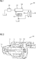
- Figure 1 shows a fluid supply system 100 according to an embodiment.
- the supply system 100 is a common rail fuel injection system for diesel or gasoline engines of a vehicle.
- the supply system 100 comprises a high pressure pump that feeds the fuel to a common rail 102 which acts as a pressure reservoir. Out of the common rail 102 the fuel can be injected to an engine wire injector 103.
- a pressure sensor 104 may be assigned to the common rail 102 to measure the pressure inside the common rail 102.
- the supply system 100 comprises a pressure control valve 110 that is an electrovalve with a variable opening pressure.
- the electrovalve comprises an electromagnet.
- the pressure control valve may be a solenoid valve. Depending on a given opening pressure for the pressure control valve 110 a maximum system pressure for the supply system 100 inside the common rail 102 can be set.
- the pressure sensor 104 is an analog high pressure sensor which is mounted to the common rail 102.
- the rail pressure sensor 104 provides an output signal in the form of a signal voltage to an engine control unit (ECU).
- ECU engine control unit
- the measured signal voltage by the ECU might drift away. That means that the measured value could differ from the actual pressure value inside the common rail 102. Such a signal drift may lead to a system overpressure and possibly to a system burst.
- Figure 2 shows the pressure control valve 110 according to an embodiment.
- the pressure control valve 110 comprises a valve pin 114. To close the pressure control valve 110 the valve pin 114 is pressed against a valve seat 115. The valve pin 114 is coupled to a pole piece 112 and an armature 113. A coil 111 surrounds the armature 113. Thus, by applying a current to coil, the valve pin 114 can be moved. The value of the current define an opening pressure of the pressure control valve 110.
- the pressure control valve 110 is used as an active pressure decrease during engine coasting mode. Most of the time, the pressure control valve 110 is controlled via open loop mode. A current is applied on the pressure control valve 110 so that the opening pressure is above the rail pressure set point or at the maximum system pressure. A safety margin may be added to the given rail pressure set point or the maximum system pressure. This means that the pressure control valve is always in a closed position during normal operation. In the case of a malfunction of the rail pressure sensor 104, e.g. a signal stuck, the pressure control valve 110 will open when the pressure inside the common rail 102 is above the opening pressure of the pressure control valve 110. The opening pressure of the pressure control valve 110 depends on the applied current. However, the expectation that the pressure will stay around the opening pressure will not be fulfilled.
- the pressure control valve 110 does not have the pressure-limiting function like a pressure-limiting valve. Unless a system overpressure is detected and further action is taken, the high pressure system 100 runs the risk of overpressure and eventual system burst. This is because a controlled pressure control valve acts as a throttle and restricts the fluid flow out of the common rail 102. The pressure control valve, which is supplied with current and/or magnetic force, pushes the valve against the valve seat. Therefore, the pressure inside the common rail 102 cannot be limited through the pressure control valve 110.
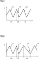
- Figure 3 shows a control signal 120 to control the pressure control valve 110 according to an embodiment.
- the control signal comprises a first frequency 121.
- the system 100 is in a normal operation.
- the pressure control valve 110 opens. This can be detected in a frequency change of the control signal 120. In Figure 3 this is shown by an increased second frequency 122 during a second period 125. During the second period 125 the valve pin 114 moves together with the pole piece 112 and the armature 113 relative to the coil 111. This induces a voltage. The voltage induced due to the movement of armature 113 leads to the change in the frequency between the first frequency 121 and the second frequency 122. By comparing the second frequency 122 with the first frequency 121 the opening of the pressure control valve 110 is detectable.
- the detected frequency change of the control signal 120 is a decreased second frequency 122 during a second period 125.
- the kind of frequency change is dependent on the design and type of the pressure control valve 110.
- the second period 125 follows directly after the first period 124.
- the first frequency 121 and the second frequency 122 that belong to directly adjacent periods of oscillation are compared.
- component tolerance and other environmental influences like temperature can be disregarded.
- the pressure inside the common rail 102 rises over the opening pressure of the pressure control valve 110.
- the frequency of the control signal 110 defines the opening pressure of the pressure control valve.
- the current applied to the pressure control valve 110 specifies the opening pressure of the pressure control valve 110.
- the pressure control valve 110 opens. The transition from the closed state to the open state has an effect on the current applied on the pressure control valve 110 due to the movement of the armature 113 relative to the coil 111. The transition from the closed state to the open position has an effect on the frequency of the control signal 120 applied on the pressure control valve 110.
- the change in the frequency is due to the pole distance variation during opening and closing of the pressure control valve 110 and the voltage induced due to the movement of the armature 113.
- an opening of the pressure control valve is detectable dependent on the frequency of the control signal 120.
- the detection of an opening of the pressure control valve 110 can be used an indicator for a system overpressure in the common rail 102. Further failure reaction is possible to prevent a system burst, for example lowering the current applied to the pressure control valve to decrease the opening pressure.
- a limitation of the pump delivery of the pump 101 is possible or a limp home mode for the vehicle is possible.
- Figure 4 shows the control signal 120 according to a further embodiment.
- a third frequency 123 is detectable.
- the third frequency 123 is different to the second frequency 122 and different to the first frequency 121.
- the third frequency 123 is smaller than the first frequency 121 and smaller than the second frequency 122.
- the applied current is increased after an initial frequency change detection in the second period 125.
- the increased applied current leads to a transition to a closed pressure control valve 110.
- the increased current defines an increased opening pressure and thus the pressure control valve 110 closes.
- the closing must lead to a change of the frequency of the control signal 120. This change from the second frequency 122 or the first frequency 121 to the third frequency 123 confirms that the pressure control valve 110 has indeed opened during the first period 124.
- a more robust detection of a system overpressure is realized.
- the third frequency 123 is greater than the first frequency 121 and greater than the second frequency 122.
- the kind of frequency change is dependent on the design and type of the pressure control valve 110.
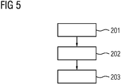
- Figure 5 shows a flowchart of a method according to an embodiment.
- step 201 the pressure control valve 110 is applied with a constant current dependent on a desired opening pressure and/or a desired maximum system pressure.
- step 202 a system overpressure detection is executed.
- the overpressure is detected dependent on a detection of an opening of the pressure control valve 110.
- the opening of the pressure control valve 110 is detected dependent on a frequency change of the control signal 120.
- the valve opening is detected via a frequency change on the applied current.
- step 203 a system burst prevention is started. For example the current applied to the pressure control valve 110 is lowered. Alternatively or in addition a pump delivery is limited, for example via a volume control valve intervention. Alternatively or in addition a limp home mode for the vehicle is initiated to prevent a further increase of the pressure inside the common rail 102.
- the proposed methods realize a low cost strategy to detect a system overpressure.
- the system overpressure is detectable via a software solution via hardware that is usually installed in the supply system 100.
- a system burst can be prevented.
Landscapes
- Engineering & Computer Science (AREA)
- Chemical & Material Sciences (AREA)
- Combustion & Propulsion (AREA)
- Mechanical Engineering (AREA)
- General Engineering & Computer Science (AREA)
- Fuel-Injection Apparatus (AREA)
Abstract
Description
- The disclosure relates to a method for operating a pressure control valve of a fluid supply system for a vehicle. The disclosure further relates to a method for operating a fluid supply system for a vehicle, in particular for a fluid supply system with a pressure control valve. The disclosure further relates to a corresponding device for operating a fluid supply system for a vehicle.
- Fluid supply systems for diesel engines or gasoline engines may work with high pressure. So-called common rail direct fuel injection systems comprise a high pressure pump for feeding a common fuel rail. For example, pressure in the rail is determined with the aid of a pressure sensor. The pump feeds fuel to the common rail dependent on a desired pressure and the signal of the pressure sensor.
- It is desirable to provide methods and devices for operating a pressure control valve of a fluid supply system for a vehicle and the fluid supply system that allow reliable operation.
- Exemplary embodiments herein provide a method for operating a pressure control valve of a fluid supply system for a vehicle.
- In particular, the method comprises: operating a pressure control valve of a fluid supply system for a vehicle, comprising:
- applying a control signal for the valve to hold the valve in a closed state dependent on a given opening pressure for the valve,
- detecting a first frequency of the control signal in a first period of oscillation,
- detecting a second frequency of the control signal in a second period of oscillation, the second period being adjacent to the first period,
- comparing the first frequency with the second frequency,
- determining an opening of the valve, if the second frequency is different from the first frequency.
- The method allows to use the pressure control valve as an indicator of the given opening pressure of the valve being exceeded. For example, the given opening pressure equals a maximum system pressure of the fluid supply system. The opening pressure of the valve may be slightly higher than the maximum system pressure. If the valve opens, the system pressure is higher than the opening pressure of the valve. Due to the detection of the frequency change in the control signal, the opening of the valve is easy and reliable to detect. The change in the frequency of the control system results from a movement of an armature of the pressure control valve from a closed state to the open state. For example, the change in the frequency is due to the pole distance variation during opening and closing of the valve and the voltage induced due to the movement of the armature. The frequency change indicates the opening of the pressure control valve which also means that the rail pressure is above the opening pressure of the pressure control valve. This information can be used to indicate that the supply system has an overpressure. A corresponding failure reaction is possible to prevent a system burst. Thus, an overpressure can be avoided even if there is a malfunction of the rail pressure sensor. If the rail pressure sensor delivers a faulty signal, e.g. a stack signal, the overpressure in the system may not be determined depending on the signal of the rail pressure sensor. By detecting the frequency change of the control signal of the pressure control valve damage to the system due to overpressure can still be avoided.
- According to further embodiments, the second period follows directly after the first period. Thus, a relative change in the signal is detectable. Therefore other influencing factors like temperature can be disregarded.
- According to further embodiments, the opening of the valve is detected if the second frequency is greater than the first frequency depending on the movement of the armature and/or the pole piece of the valve relative to a coil of the valve. According to further embodiments, the opening of the valve is detected if the second frequency is smaller than the first frequency depending on the movement of the armature and/or the pole piece of the valve relative to a coil of the valve.
- The movement of the armature and/or the pole piece has an effect on the signal applied to the pressure control valve. The pole distance has an effect on the signal applied to the pressure control valve. In particular, the transition from closed to open has an effect on the current applied on the pressure control valve due to the movement of the armature. In particular, the transition from closed to open has an effect on the frequency with which the intensity of the current changes. The frequency is higher or lower when the pressure control valve opens dependent on the design of pressure control valve itself. A frequency increase or a frequency decrease can be detected depending on the design of the pressure control valve. In particular, the frequency change is detectable when the current of the pressure control valve is controlled via a current close loop control. The frequency change is due to the change of current gradient which is in particular based on the combination of two physical event: a current induction due to the movement of the anchor and an inductivity change due to a change in the pole distance (air gap). If the current of the pressure control valve is controlled via a PWM (pulse-width modulation) based control, in particular a fixed PWM control, a current change due to the change in current gradient can be detected. For example, a change in an average current is detected, if the pressure control valve opens. For example, a change in an average current is detected, if the pressure control valve closes.
- According to further embodiments, the method comprises:
- applying the control signal to hold the valve in a closed state with an opening pressure greater than the given opening pressure for the valve in a third period of oscillation, the third period being subsequent to the second period,
- detecting a third frequency of the control signal in the third period,
- comparing the third frequency with the first frequency,
- determining a closing of the valve, if the third frequency is smaller than the first frequency.
- Thus, it is possible to have a further transition from the open state to the closed state of the pressure control valve. By increasing the opening pressure, the pressure control closes. If there is a change in the frequency after the opening pressure has been increased, this is a sign that the pressure control valve has moved from the open state to the closed state. That confirms that the pressure control valve has opened in the second period. Thus a more robust detection is possible.
- According to further embodiments, a control signal to hold the valve in a closed state with an opening pressure smaller than the given opening pressure is applied in response to determining the opening of the valve. Thus, it is possible to reduce the pressure in the supply system to avoid an overpressure and a system burst.
- According to a further aspect, a method for operating a fluid supply system for a vehicle comprises determining an overpressure in the fluid supply system if an opening of the pressure control valve has been detected.
- According to further embodiments, an overpressure in a common rail of the supply system is determined dependent on the detection of the opening of the valve. The overpressure in the common rail is detected independent of the signal of a pressure signal of the common rail. According to further embodiments, a fluid delivery of a pump of the supply system is limited in response to determining the opening of the valve. Thus, it is possible to lower the system pressure.
- According to further embodiments, a malfunction of the pressure sensor of the supply system is determined depending on the opening of the valve. If the opening of the pressure control valve has been detected and a signal of the pressure sensor indicates a pressure below the maximum system pressure, this indicates a malfunction of the pressure sensor.
- According to a further aspect, a device for operating a fluid supply system for a vehicle is described, wherein the device is configured to execute a method according to at least one of the embodiments explained above.
- By detecting an overpressure in a fluid supply system in response to an opening of the pressure control valve, a low cost software solution is possible. The described methods allow a low cost strategy to detect system overpressure and prevent an eventual system burst. Furthermore, the detection is based on the relative change of frequency which is not affected by component tolerances and other environmental influences.
- The present invention will be further described with reference to the accompanying drawings, wherein:
-
Figure 1 shows a schematic diagram of a fluid supply system according to an embodiment; -
Figure 2 shows a schematic diagram of a pressure control valve according to an embodiment; -
Figures 3 and 4 each show a schematic signal path according to embodiments; and -
Figure 5 shows a flowchart of a method according to an embodiment. - While the invention is amenable to various modifications and alternative forms, specifics thereof have been shown by way of example in the drawings and will be described in detail.
- In the following detailed description of embodiments, reference is made to the accompanying drawings, which form a part hereof and in which are shown, by way of illustration, specific embodiments in which the invention may be practiced. The illustrated embodiments are not intended to be exhaustive of all embodiments according to the invention.
-
Figure 1 shows afluid supply system 100 according to an embodiment. In particular, thesupply system 100 is a common rail fuel injection system for diesel or gasoline engines of a vehicle. - The
supply system 100 comprises a high pressure pump that feeds the fuel to acommon rail 102 which acts as a pressure reservoir. Out of thecommon rail 102 the fuel can be injected to anengine wire injector 103. - A
pressure sensor 104 may be assigned to thecommon rail 102 to measure the pressure inside thecommon rail 102. - The
supply system 100 comprises apressure control valve 110 that is an electrovalve with a variable opening pressure. The electrovalve comprises an electromagnet. The pressure control valve may be a solenoid valve. Depending on a given opening pressure for the pressure control valve 110 a maximum system pressure for thesupply system 100 inside thecommon rail 102 can be set. - For example, the
pressure sensor 104 is an analog high pressure sensor which is mounted to thecommon rail 102. Therail pressure sensor 104 provides an output signal in the form of a signal voltage to an engine control unit (ECU). The measured signal voltage by the ECU might drift away. That means that the measured value could differ from the actual pressure value inside thecommon rail 102. Such a signal drift may lead to a system overpressure and possibly to a system burst. -
Figure 2 shows thepressure control valve 110 according to an embodiment. - The
pressure control valve 110 comprises avalve pin 114. To close thepressure control valve 110 thevalve pin 114 is pressed against avalve seat 115. Thevalve pin 114 is coupled to apole piece 112 and anarmature 113. Acoil 111 surrounds thearmature 113. Thus, by applying a current to coil, thevalve pin 114 can be moved. The value of the current define an opening pressure of thepressure control valve 110. - The
pressure control valve 110 is used as an active pressure decrease during engine coasting mode. Most of the time, thepressure control valve 110 is controlled via open loop mode. A current is applied on thepressure control valve 110 so that the opening pressure is above the rail pressure set point or at the maximum system pressure. A safety margin may be added to the given rail pressure set point or the maximum system pressure. This means that the pressure control valve is always in a closed position during normal operation. In the case of a malfunction of therail pressure sensor 104, e.g. a signal stuck, thepressure control valve 110 will open when the pressure inside thecommon rail 102 is above the opening pressure of thepressure control valve 110. The opening pressure of thepressure control valve 110 depends on the applied current. However, the expectation that the pressure will stay around the opening pressure will not be fulfilled. The reason for this is that thepressure control valve 110 does not have the pressure-limiting function like a pressure-limiting valve. Unless a system overpressure is detected and further action is taken, thehigh pressure system 100 runs the risk of overpressure and eventual system burst. This is because a controlled pressure control valve acts as a throttle and restricts the fluid flow out of thecommon rail 102. The pressure control valve, which is supplied with current and/or magnetic force, pushes the valve against the valve seat. Therefore, the pressure inside thecommon rail 102 cannot be limited through thepressure control valve 110. -
Figure 3 shows acontrol signal 120 to control thepressure control valve 110 according to an embodiment. During afirst period 124 the control signal comprises afirst frequency 121. During thefirst period 124 thesystem 100 is in a normal operation. - If the pressure inside the
common rail 102 rises up over the given opening pressure of thepressure control valve 110, thepressure control valve 110 opens. This can be detected in a frequency change of thecontrol signal 120. InFigure 3 this is shown by an increasedsecond frequency 122 during asecond period 125. During thesecond period 125 thevalve pin 114 moves together with thepole piece 112 and thearmature 113 relative to thecoil 111. This induces a voltage. The voltage induced due to the movement ofarmature 113 leads to the change in the frequency between thefirst frequency 121 and thesecond frequency 122. By comparing thesecond frequency 122 with thefirst frequency 121 the opening of thepressure control valve 110 is detectable. - According to further embodiments, the detected frequency change of the
control signal 120 is a decreasedsecond frequency 122 during asecond period 125. The kind of frequency change is dependent on the design and type of thepressure control valve 110. - According to embodiments, the
second period 125 follows directly after thefirst period 124. Thefirst frequency 121 and thesecond frequency 122 that belong to directly adjacent periods of oscillation are compared. Thus, component tolerance and other environmental influences like temperature can be disregarded. - In particular, if there is a malfunction of the
rail pressure sensor 104, the pressure inside thecommon rail 102 rises over the opening pressure of thepressure control valve 110. The frequency of thecontrol signal 110 defines the opening pressure of the pressure control valve. In particular, the current applied to thepressure control valve 110 specifies the opening pressure of thepressure control valve 110. In response to the pressure inside thecommon rail 102 being higher than the opening pressure of thepressure control valve 110, thepressure control valve 110 opens. The transition from the closed state to the open state has an effect on the current applied on thepressure control valve 110 due to the movement of thearmature 113 relative to thecoil 111. The transition from the closed state to the open position has an effect on the frequency of thecontrol signal 120 applied on thepressure control valve 110. The change in the frequency is due to the pole distance variation during opening and closing of thepressure control valve 110 and the voltage induced due to the movement of thearmature 113. Thus, an opening of the pressure control valve is detectable dependent on the frequency of thecontrol signal 120. The detection of an opening of thepressure control valve 110 can be used an indicator for a system overpressure in thecommon rail 102. Further failure reaction is possible to prevent a system burst, for example lowering the current applied to the pressure control valve to decrease the opening pressure. Furthermore, a limitation of the pump delivery of thepump 101 is possible or a limp home mode for the vehicle is possible. -
Figure 4 shows thecontrol signal 120 according to a further embodiment. - After detection of the opening of the
pressure control valve 110 during thesecond period 125 the applied current is increased. Thus, in athird period 126 after the second period 125 athird frequency 123 is detectable. Thethird frequency 123 is different to thesecond frequency 122 and different to thefirst frequency 121. In particular, thethird frequency 123 is smaller than thefirst frequency 121 and smaller than thesecond frequency 122. The applied current is increased after an initial frequency change detection in thesecond period 125. The increased applied current leads to a transition to a closedpressure control valve 110. The increased current defines an increased opening pressure and thus thepressure control valve 110 closes. The closing must lead to a change of the frequency of thecontrol signal 120. This change from thesecond frequency 122 or thefirst frequency 121 to thethird frequency 123 confirms that thepressure control valve 110 has indeed opened during thefirst period 124. Thus, a more robust detection of a system overpressure is realized. - According to further embodiments, the
third frequency 123 is greater than thefirst frequency 121 and greater than thesecond frequency 122. The kind of frequency change is dependent on the design and type of thepressure control valve 110. -
Figure 5 shows a flowchart of a method according to an embodiment. - During
step 201 thepressure control valve 110 is applied with a constant current dependent on a desired opening pressure and/or a desired maximum system pressure. - In step 202 a system overpressure detection is executed. The overpressure is detected dependent on a detection of an opening of the
pressure control valve 110. The opening of thepressure control valve 110 is detected dependent on a frequency change of thecontrol signal 120. The valve opening is detected via a frequency change on the applied current. - In step 203 a system burst prevention is started. For example the current applied to the
pressure control valve 110 is lowered. Alternatively or in addition a pump delivery is limited, for example via a volume control valve intervention. Alternatively or in addition a limp home mode for the vehicle is initiated to prevent a further increase of the pressure inside thecommon rail 102. - The proposed methods realize a low cost strategy to detect a system overpressure. The system overpressure is detectable via a software solution via hardware that is usually installed in the
supply system 100. Thus, even with a malfunctioning pressure sensor 104 a system burst can be prevented.
Claims (10)
- Method for operating a pressure control valve (110) of a fluid supply system (100) for a vehicle, comprising:- applying a control signal (120) for the valve (110) to hold the valve (110) in a closed state dependent on a given opening pressure for the valve (110),- detecting a first frequency (121) of the control signal (120) in a first period (124) of oscillation,- detecting a second frequency (122) of the control signal (120) in a second period (125) of oscillation, the second period (125) being adjacent to the first period (124),- comparing the first frequency (121) with the second frequency (122),- determining an opening of the valve (110), if the second frequency (122) is different from the first frequency (121).
- Method according to claim 1, wherein the second period (125) follows directly after the first period (124).
- Method according to claim 1 or claim 2, comprising:- determining the opening, if the second frequency (122) is greater than the first frequency (121) or smaller than the first frequency (121), dependent on a movement of an armature (113) and/or a pole piece (122) of the valve (110) relative to a coil (111) of the valve (110).
- Method according to any one of claims 1 to 3, comprising:- applying the control signal (120) to hold the valve (110) in a closed state with an opening pressure greater than the given opening pressure for the valve (110) in a third period (126) of oscillation, the third period (126) being subsequent to the second period (122),- detecting a third frequency (123) of the control signal (120) in the third period (126),- comparing the third frequency (123) with the first frequency (121),- determining a closing of the valve (110), if the third frequency (123) is smaller than the first frequency (121).
- Method according to any one of claims 1 to 4, comprising:- applying the control signal (120) to hold the valve (110) in a closed state with an opening pressure smaller than the given opening pressure in response to determining the opening of the valve (110).
- Method for operating a fluid supply system (100) for a vehicle, wherein the fluid supply system (100) comprises a pressure control valve (110), comprising:- if an opening of the valve (110) has been detected with a method according to any one of claims 1 to 5, determining an overpressure in the fluid supply system (100).
- Method according to claim 6, comprising:- determining an overpressure in a common rail (102) of the supply system (100) dependent on the detection of the opening of the valve (110).
- Method according to claim 6 or claim 7, comprising:- limiting of a fluid delivery of a pump (101) of the supply system (100) in response to determining the opening of the valve (110).
- Method according to any one of claims 6 to 8, comprising:- determining a malfunction of a pressure sensor (104) of the supply system (100) dependent on the opening of the valve (110) .
- Device for operating a fluid supply system (100) for a vehicle, wherein the device is configured to execute a method according to any one of the claims 1 to 9.
Priority Applications (1)
| Application Number | Priority Date | Filing Date | Title |
|---|---|---|---|
| EP19164188.5A EP3712418B1 (en) | 2019-03-20 | 2019-03-20 | Method for operating a pressure control valve, method for operating a fluid supply system and device for operating a fluid supply system |
Applications Claiming Priority (1)
| Application Number | Priority Date | Filing Date | Title |
|---|---|---|---|
| EP19164188.5A EP3712418B1 (en) | 2019-03-20 | 2019-03-20 | Method for operating a pressure control valve, method for operating a fluid supply system and device for operating a fluid supply system |
Publications (2)
| Publication Number | Publication Date |
|---|---|
| EP3712418A1 true EP3712418A1 (en) | 2020-09-23 |
| EP3712418B1 EP3712418B1 (en) | 2023-07-12 |
Family
ID=65894903
Family Applications (1)
| Application Number | Title | Priority Date | Filing Date |
|---|---|---|---|
| EP19164188.5A Active EP3712418B1 (en) | 2019-03-20 | 2019-03-20 | Method for operating a pressure control valve, method for operating a fluid supply system and device for operating a fluid supply system |
Country Status (1)
| Country | Link |
|---|---|
| EP (1) | EP3712418B1 (en) |
Citations (5)
| Publication number | Priority date | Publication date | Assignee | Title |
|---|---|---|---|---|
| DE102012203283A1 (en) * | 2012-03-02 | 2013-09-05 | Continental Automotive Gmbh | Method for checking plausibility of function of pressure sensor of injection system of engine, involves determining pressure of system, based on maximum output signal of sensor according to detected actuation of throw-off mechanism |
| DE102013202266A1 (en) * | 2013-02-12 | 2014-08-14 | Robert Bosch Gmbh | Method for monitoring common-rail-injection system in self-ignition internal combustion engine of motor car, involves generating temporary error reaction, and cancelling reaction when presence of overpressure situations is not acknowledged |
| US20170107931A1 (en) * | 2014-04-03 | 2017-04-20 | Continental Automotive Gmbh | Method and device for operating a pressure reservoir, in particular for common rail injection systems in automobile engineering |
| EP3385528A1 (en) * | 2017-04-06 | 2018-10-10 | Continental Automotive GmbH | Method for detecting a switching point of a switchable solenoid valve, electronic circuit, pump and motor vehicle |
| EP3385527A1 (en) * | 2017-04-06 | 2018-10-10 | Continental Automotive GmbH | Method for detecting a failed actuation of a switchable solenoid valve, electronic circuit for performing the method, pump and motor vehicle |
-
2019
- 2019-03-20 EP EP19164188.5A patent/EP3712418B1/en active Active
Patent Citations (5)
| Publication number | Priority date | Publication date | Assignee | Title |
|---|---|---|---|---|
| DE102012203283A1 (en) * | 2012-03-02 | 2013-09-05 | Continental Automotive Gmbh | Method for checking plausibility of function of pressure sensor of injection system of engine, involves determining pressure of system, based on maximum output signal of sensor according to detected actuation of throw-off mechanism |
| DE102013202266A1 (en) * | 2013-02-12 | 2014-08-14 | Robert Bosch Gmbh | Method for monitoring common-rail-injection system in self-ignition internal combustion engine of motor car, involves generating temporary error reaction, and cancelling reaction when presence of overpressure situations is not acknowledged |
| US20170107931A1 (en) * | 2014-04-03 | 2017-04-20 | Continental Automotive Gmbh | Method and device for operating a pressure reservoir, in particular for common rail injection systems in automobile engineering |
| EP3385528A1 (en) * | 2017-04-06 | 2018-10-10 | Continental Automotive GmbH | Method for detecting a switching point of a switchable solenoid valve, electronic circuit, pump and motor vehicle |
| EP3385527A1 (en) * | 2017-04-06 | 2018-10-10 | Continental Automotive GmbH | Method for detecting a failed actuation of a switchable solenoid valve, electronic circuit for performing the method, pump and motor vehicle |
Also Published As
| Publication number | Publication date |
|---|---|
| EP3712418B1 (en) | 2023-07-12 |
Similar Documents
| Publication | Publication Date | Title |
|---|---|---|
| US9512801B2 (en) | Fuel injection controller | |
| CN101983284B (en) | Method and apparatus for controlling a fuel metering system | |
| US9970376B2 (en) | Fuel injection controller and fuel injection system | |
| CN106062352B (en) | Method for adjusting a common rail injector | |
| US9447893B2 (en) | Method and device for controlling a valve | |
| JP3871375B2 (en) | Fuel injection device for internal combustion engine | |
| JP3902692B2 (en) | Method and apparatus for monitoring an injection system | |
| JP4093696B2 (en) | Depressurization regulating valve for fuel injection device | |
| US20090217914A1 (en) | Method for driving solenoid-actuated fuel injectors of internal combustion engines | |
| US20150122000A1 (en) | Method for detecting an error in the opening behavior of an injector | |
| EP2116710B1 (en) | Fuel pressure controller and fuel pressure control system | |
| US11795887B1 (en) | Fuel injector variability reduction | |
| US10648419B2 (en) | Fuel injection control device and fuel injection system | |
| US11293370B1 (en) | Method and system for valve position monitoring | |
| JP2019210933A (en) | Method for determining closing point of electromagnetic fuel injector | |
| US7413160B2 (en) | Method for determining a closing time of a closing element and circuit arrangement | |
| US10473050B2 (en) | Pressure accumulator device for a motor vehicle fuel injection system, and method for operating a pressure accumulator device of said type | |
| US9714632B2 (en) | Method and device for controlling a quantity control valve | |
| JP2006077627A (en) | Fuel injection device | |
| EP3712418A1 (en) | Method for operating a pressure control valve, method for operating a fluid supply system and device for operating a fluid supply system | |
| US5947382A (en) | Servo controlled common rail injector | |
| KR20210104317A (en) | Apparatus and method for controlling fuel injection for improving the deviation of opening duration of injector | |
| KR102169756B1 (en) | Method of operating high pressure pump of high pressure injection system of automobile, and control device and automobile | |
| JP6835960B2 (en) | Methods, controls, high pressure injection systems, and automobiles for checking the calibration of pressure sensors in automobile injection systems. | |
| US7216669B2 (en) | Pressure regulating valve for common rail fuel injection systems |
Legal Events
| Date | Code | Title | Description |
|---|---|---|---|
| PUAI | Public reference made under article 153(3) epc to a published international application that has entered the european phase |
Free format text: ORIGINAL CODE: 0009012 |
|
| STAA | Information on the status of an ep patent application or granted ep patent |
Free format text: STATUS: THE APPLICATION HAS BEEN PUBLISHED |
|
| AK | Designated contracting states |
Kind code of ref document: A1 Designated state(s): AL AT BE BG CH CY CZ DE DK EE ES FI FR GB GR HR HU IE IS IT LI LT LU LV MC MK MT NL NO PL PT RO RS SE SI SK SM TR |
|
| AX | Request for extension of the european patent |
Extension state: BA ME |
|
| STAA | Information on the status of an ep patent application or granted ep patent |
Free format text: STATUS: REQUEST FOR EXAMINATION WAS MADE |
|
| 17P | Request for examination filed |
Effective date: 20210317 |
|
| RBV | Designated contracting states (corrected) |
Designated state(s): AL AT BE BG CH CY CZ DE DK EE ES FI FR GB GR HR HU IE IS IT LI LT LU LV MC MK MT NL NO PL PT RO RS SE SI SK SM TR |
|
| RAP3 | Party data changed (applicant data changed or rights of an application transferred) |
Owner name: VITESCO TECHNOLOGIES GMBH |
|
| GRAP | Despatch of communication of intention to grant a patent |
Free format text: ORIGINAL CODE: EPIDOSNIGR1 |
|
| STAA | Information on the status of an ep patent application or granted ep patent |
Free format text: STATUS: GRANT OF PATENT IS INTENDED |
|
| INTG | Intention to grant announced |
Effective date: 20230214 |
|
| GRAS | Grant fee paid |
Free format text: ORIGINAL CODE: EPIDOSNIGR3 |
|
| GRAA | (expected) grant |
Free format text: ORIGINAL CODE: 0009210 |
|
| STAA | Information on the status of an ep patent application or granted ep patent |
Free format text: STATUS: THE PATENT HAS BEEN GRANTED |
|
| AK | Designated contracting states |
Kind code of ref document: B1 Designated state(s): AL AT BE BG CH CY CZ DE DK EE ES FI FR GB GR HR HU IE IS IT LI LT LU LV MC MK MT NL NO PL PT RO RS SE SI SK SM TR |
|
| P01 | Opt-out of the competence of the unified patent court (upc) registered |
Effective date: 20230530 |
|
| REG | Reference to a national code |
Ref country code: CH Ref legal event code: EP |
|
| REG | Reference to a national code |
Ref country code: IE Ref legal event code: FG4D |
|
| REG | Reference to a national code |
Ref country code: DE Ref legal event code: R096 Ref document number: 602019032403 Country of ref document: DE |
|
| REG | Reference to a national code |
Ref country code: LT Ref legal event code: MG9D |
|
| REG | Reference to a national code |
Ref country code: NL Ref legal event code: MP Effective date: 20230712 |
|
| REG | Reference to a national code |
Ref country code: AT Ref legal event code: MK05 Ref document number: 1587408 Country of ref document: AT Kind code of ref document: T Effective date: 20230712 |
|
| PG25 | Lapsed in a contracting state [announced via postgrant information from national office to epo] |
Ref country code: NL Free format text: LAPSE BECAUSE OF FAILURE TO SUBMIT A TRANSLATION OF THE DESCRIPTION OR TO PAY THE FEE WITHIN THE PRESCRIBED TIME-LIMIT Effective date: 20230712 |
|
| PG25 | Lapsed in a contracting state [announced via postgrant information from national office to epo] |
Ref country code: GR Free format text: LAPSE BECAUSE OF FAILURE TO SUBMIT A TRANSLATION OF THE DESCRIPTION OR TO PAY THE FEE WITHIN THE PRESCRIBED TIME-LIMIT Effective date: 20231013 |
|
| PG25 | Lapsed in a contracting state [announced via postgrant information from national office to epo] |
Ref country code: ES Free format text: LAPSE BECAUSE OF FAILURE TO SUBMIT A TRANSLATION OF THE DESCRIPTION OR TO PAY THE FEE WITHIN THE PRESCRIBED TIME-LIMIT Effective date: 20230712 |
|
| PG25 | Lapsed in a contracting state [announced via postgrant information from national office to epo] |
Ref country code: IS Free format text: LAPSE BECAUSE OF FAILURE TO SUBMIT A TRANSLATION OF THE DESCRIPTION OR TO PAY THE FEE WITHIN THE PRESCRIBED TIME-LIMIT Effective date: 20231112 |
|
| PG25 | Lapsed in a contracting state [announced via postgrant information from national office to epo] |
Ref country code: SE Free format text: LAPSE BECAUSE OF FAILURE TO SUBMIT A TRANSLATION OF THE DESCRIPTION OR TO PAY THE FEE WITHIN THE PRESCRIBED TIME-LIMIT Effective date: 20230712 Ref country code: RS Free format text: LAPSE BECAUSE OF FAILURE TO SUBMIT A TRANSLATION OF THE DESCRIPTION OR TO PAY THE FEE WITHIN THE PRESCRIBED TIME-LIMIT Effective date: 20230712 Ref country code: PT Free format text: LAPSE BECAUSE OF FAILURE TO SUBMIT A TRANSLATION OF THE DESCRIPTION OR TO PAY THE FEE WITHIN THE PRESCRIBED TIME-LIMIT Effective date: 20231113 Ref country code: NO Free format text: LAPSE BECAUSE OF FAILURE TO SUBMIT A TRANSLATION OF THE DESCRIPTION OR TO PAY THE FEE WITHIN THE PRESCRIBED TIME-LIMIT Effective date: 20231012 Ref country code: LV Free format text: LAPSE BECAUSE OF FAILURE TO SUBMIT A TRANSLATION OF THE DESCRIPTION OR TO PAY THE FEE WITHIN THE PRESCRIBED TIME-LIMIT Effective date: 20230712 Ref country code: LT Free format text: LAPSE BECAUSE OF FAILURE TO SUBMIT A TRANSLATION OF THE DESCRIPTION OR TO PAY THE FEE WITHIN THE PRESCRIBED TIME-LIMIT Effective date: 20230712 Ref country code: IS Free format text: LAPSE BECAUSE OF FAILURE TO SUBMIT A TRANSLATION OF THE DESCRIPTION OR TO PAY THE FEE WITHIN THE PRESCRIBED TIME-LIMIT Effective date: 20231112 Ref country code: HR Free format text: LAPSE BECAUSE OF FAILURE TO SUBMIT A TRANSLATION OF THE DESCRIPTION OR TO PAY THE FEE WITHIN THE PRESCRIBED TIME-LIMIT Effective date: 20230712 Ref country code: GR Free format text: LAPSE BECAUSE OF FAILURE TO SUBMIT A TRANSLATION OF THE DESCRIPTION OR TO PAY THE FEE WITHIN THE PRESCRIBED TIME-LIMIT Effective date: 20231013 Ref country code: FI Free format text: LAPSE BECAUSE OF FAILURE TO SUBMIT A TRANSLATION OF THE DESCRIPTION OR TO PAY THE FEE WITHIN THE PRESCRIBED TIME-LIMIT Effective date: 20230712 Ref country code: ES Free format text: LAPSE BECAUSE OF FAILURE TO SUBMIT A TRANSLATION OF THE DESCRIPTION OR TO PAY THE FEE WITHIN THE PRESCRIBED TIME-LIMIT Effective date: 20230712 Ref country code: AT Free format text: LAPSE BECAUSE OF FAILURE TO SUBMIT A TRANSLATION OF THE DESCRIPTION OR TO PAY THE FEE WITHIN THE PRESCRIBED TIME-LIMIT Effective date: 20230712 |
|
| PG25 | Lapsed in a contracting state [announced via postgrant information from national office to epo] |
Ref country code: PL Free format text: LAPSE BECAUSE OF FAILURE TO SUBMIT A TRANSLATION OF THE DESCRIPTION OR TO PAY THE FEE WITHIN THE PRESCRIBED TIME-LIMIT Effective date: 20230712 |
|
| REG | Reference to a national code |
Ref country code: DE Ref legal event code: R097 Ref document number: 602019032403 Country of ref document: DE |
|
| PG25 | Lapsed in a contracting state [announced via postgrant information from national office to epo] |
Ref country code: SM Free format text: LAPSE BECAUSE OF FAILURE TO SUBMIT A TRANSLATION OF THE DESCRIPTION OR TO PAY THE FEE WITHIN THE PRESCRIBED TIME-LIMIT Effective date: 20230712 Ref country code: RO Free format text: LAPSE BECAUSE OF FAILURE TO SUBMIT A TRANSLATION OF THE DESCRIPTION OR TO PAY THE FEE WITHIN THE PRESCRIBED TIME-LIMIT Effective date: 20230712 Ref country code: EE Free format text: LAPSE BECAUSE OF FAILURE TO SUBMIT A TRANSLATION OF THE DESCRIPTION OR TO PAY THE FEE WITHIN THE PRESCRIBED TIME-LIMIT Effective date: 20230712 Ref country code: DK Free format text: LAPSE BECAUSE OF FAILURE TO SUBMIT A TRANSLATION OF THE DESCRIPTION OR TO PAY THE FEE WITHIN THE PRESCRIBED TIME-LIMIT Effective date: 20230712 Ref country code: CZ Free format text: LAPSE BECAUSE OF FAILURE TO SUBMIT A TRANSLATION OF THE DESCRIPTION OR TO PAY THE FEE WITHIN THE PRESCRIBED TIME-LIMIT Effective date: 20230712 Ref country code: SK Free format text: LAPSE BECAUSE OF FAILURE TO SUBMIT A TRANSLATION OF THE DESCRIPTION OR TO PAY THE FEE WITHIN THE PRESCRIBED TIME-LIMIT Effective date: 20230712 |
|
| PLBE | No opposition filed within time limit |
Free format text: ORIGINAL CODE: 0009261 |
|
| STAA | Information on the status of an ep patent application or granted ep patent |
Free format text: STATUS: NO OPPOSITION FILED WITHIN TIME LIMIT |
|
| PG25 | Lapsed in a contracting state [announced via postgrant information from national office to epo] |
Ref country code: IT Free format text: LAPSE BECAUSE OF FAILURE TO SUBMIT A TRANSLATION OF THE DESCRIPTION OR TO PAY THE FEE WITHIN THE PRESCRIBED TIME-LIMIT Effective date: 20230712 |
|
| 26N | No opposition filed |
Effective date: 20240415 |
|
| PG25 | Lapsed in a contracting state [announced via postgrant information from national office to epo] |
Ref country code: SI Free format text: LAPSE BECAUSE OF FAILURE TO SUBMIT A TRANSLATION OF THE DESCRIPTION OR TO PAY THE FEE WITHIN THE PRESCRIBED TIME-LIMIT Effective date: 20230712 |
|
| REG | Reference to a national code |
Ref country code: CH Ref legal event code: PL |
|
| PG25 | Lapsed in a contracting state [announced via postgrant information from national office to epo] |
Ref country code: BG Free format text: LAPSE BECAUSE OF FAILURE TO SUBMIT A TRANSLATION OF THE DESCRIPTION OR TO PAY THE FEE WITHIN THE PRESCRIBED TIME-LIMIT Effective date: 20230712 |
|
| PG25 | Lapsed in a contracting state [announced via postgrant information from national office to epo] |
Ref country code: LU Free format text: LAPSE BECAUSE OF NON-PAYMENT OF DUE FEES Effective date: 20240320 |
|
| PG25 | Lapsed in a contracting state [announced via postgrant information from national office to epo] |
Ref country code: MC Free format text: LAPSE BECAUSE OF FAILURE TO SUBMIT A TRANSLATION OF THE DESCRIPTION OR TO PAY THE FEE WITHIN THE PRESCRIBED TIME-LIMIT Effective date: 20230712 |
|
| GBPC | Gb: european patent ceased through non-payment of renewal fee |
Effective date: 20240320 |
|
| PG25 | Lapsed in a contracting state [announced via postgrant information from national office to epo] |
Ref country code: MC Free format text: LAPSE BECAUSE OF FAILURE TO SUBMIT A TRANSLATION OF THE DESCRIPTION OR TO PAY THE FEE WITHIN THE PRESCRIBED TIME-LIMIT Effective date: 20230712 Ref country code: LU Free format text: LAPSE BECAUSE OF NON-PAYMENT OF DUE FEES Effective date: 20240320 Ref country code: BG Free format text: LAPSE BECAUSE OF FAILURE TO SUBMIT A TRANSLATION OF THE DESCRIPTION OR TO PAY THE FEE WITHIN THE PRESCRIBED TIME-LIMIT Effective date: 20230712 |
|
| REG | Reference to a national code |
Ref country code: BE Ref legal event code: MM Effective date: 20240331 |
|
| PG25 | Lapsed in a contracting state [announced via postgrant information from national office to epo] |
Ref country code: BE Free format text: LAPSE BECAUSE OF NON-PAYMENT OF DUE FEES Effective date: 20240331 |
|
| PG25 | Lapsed in a contracting state [announced via postgrant information from national office to epo] |
Ref country code: GB Free format text: LAPSE BECAUSE OF NON-PAYMENT OF DUE FEES Effective date: 20240320 |
|
| PG25 | Lapsed in a contracting state [announced via postgrant information from national office to epo] |
Ref country code: FR Free format text: LAPSE BECAUSE OF NON-PAYMENT OF DUE FEES Effective date: 20240331 |
|
| PG25 | Lapsed in a contracting state [announced via postgrant information from national office to epo] |
Ref country code: IE Free format text: LAPSE BECAUSE OF NON-PAYMENT OF DUE FEES Effective date: 20240320 |
|
| PG25 | Lapsed in a contracting state [announced via postgrant information from national office to epo] |
Ref country code: IE Free format text: LAPSE BECAUSE OF NON-PAYMENT OF DUE FEES Effective date: 20240320 Ref country code: GB Free format text: LAPSE BECAUSE OF NON-PAYMENT OF DUE FEES Effective date: 20240320 Ref country code: FR Free format text: LAPSE BECAUSE OF NON-PAYMENT OF DUE FEES Effective date: 20240331 Ref country code: BE Free format text: LAPSE BECAUSE OF NON-PAYMENT OF DUE FEES Effective date: 20240331 Ref country code: CH Free format text: LAPSE BECAUSE OF NON-PAYMENT OF DUE FEES Effective date: 20240331 |
|
| REG | Reference to a national code |
Ref country code: DE Ref legal event code: R081 Ref document number: 602019032403 Country of ref document: DE Owner name: SCHAEFFLER TECHNOLOGIES AG & CO. KG, DE Free format text: FORMER OWNER: VITESCO TECHNOLOGIES GMBH, 93055 REGENSBURG, DE |
|
| PG25 | Lapsed in a contracting state [announced via postgrant information from national office to epo] |
Ref country code: CY Free format text: LAPSE BECAUSE OF FAILURE TO SUBMIT A TRANSLATION OF THE DESCRIPTION OR TO PAY THE FEE WITHIN THE PRESCRIBED TIME-LIMIT; INVALID AB INITIO Effective date: 20190320 |
|
| PG25 | Lapsed in a contracting state [announced via postgrant information from national office to epo] |
Ref country code: HU Free format text: LAPSE BECAUSE OF FAILURE TO SUBMIT A TRANSLATION OF THE DESCRIPTION OR TO PAY THE FEE WITHIN THE PRESCRIBED TIME-LIMIT; INVALID AB INITIO Effective date: 20190320 |
|
| PG25 | Lapsed in a contracting state [announced via postgrant information from national office to epo] |
Ref country code: TR Free format text: LAPSE BECAUSE OF FAILURE TO SUBMIT A TRANSLATION OF THE DESCRIPTION OR TO PAY THE FEE WITHIN THE PRESCRIBED TIME-LIMIT Effective date: 20230712 |
|
| PGFP | Annual fee paid to national office [announced via postgrant information from national office to epo] |
Ref country code: DE Payment date: 20260331 Year of fee payment: 8 |