EP3712404B1 - Turbine engine configuration including pylon mounted heat exchanger - Google Patents
Turbine engine configuration including pylon mounted heat exchanger Download PDFInfo
- Publication number
- EP3712404B1 EP3712404B1 EP20164843.3A EP20164843A EP3712404B1 EP 3712404 B1 EP3712404 B1 EP 3712404B1 EP 20164843 A EP20164843 A EP 20164843A EP 3712404 B1 EP3712404 B1 EP 3712404B1
- Authority
- EP
- European Patent Office
- Prior art keywords
- engine
- heat exchanger
- air
- engine system
- cooling fluid
- Prior art date
- Legal status (The legal status is an assumption and is not a legal conclusion. Google has not performed a legal analysis and makes no representation as to the accuracy of the status listed.)
- Active
Links
Images


Classifications
-
- F—MECHANICAL ENGINEERING; LIGHTING; HEATING; WEAPONS; BLASTING
- F02—COMBUSTION ENGINES; HOT-GAS OR COMBUSTION-PRODUCT ENGINE PLANTS
- F02K—JET-PROPULSION PLANTS
- F02K3/00—Plants including a gas turbine driving a compressor or a ducted fan
- F02K3/08—Plants including a gas turbine driving a compressor or a ducted fan with supplementary heating of the working fluid; Control thereof
- F02K3/105—Heating the by-pass flow
- F02K3/115—Heating the by-pass flow by means of indirect heat exchange
-
- B—PERFORMING OPERATIONS; TRANSPORTING
- B64—AIRCRAFT; AVIATION; COSMONAUTICS
- B64D—EQUIPMENT FOR FITTING IN OR TO AIRCRAFT; FLIGHT SUITS; PARACHUTES; ARRANGEMENT OR MOUNTING OF POWER PLANTS OR PROPULSION TRANSMISSIONS IN AIRCRAFT
- B64D13/00—Arrangements or adaptations of air-treatment apparatus for aircraft crew or passengers, or freight space
- B64D13/06—Arrangements or adaptations of air-treatment apparatus for aircraft crew or passengers, or freight space the air being conditioned
- B64D13/08—Arrangements or adaptations of air-treatment apparatus for aircraft crew or passengers, or freight space the air being conditioned the air being heated or cooled
-
- B—PERFORMING OPERATIONS; TRANSPORTING
- B64—AIRCRAFT; AVIATION; COSMONAUTICS
- B64D—EQUIPMENT FOR FITTING IN OR TO AIRCRAFT; FLIGHT SUITS; PARACHUTES; ARRANGEMENT OR MOUNTING OF POWER PLANTS OR PROPULSION TRANSMISSIONS IN AIRCRAFT
- B64D33/00—Arrangement in aircraft of power plant parts or auxiliaries not otherwise provided for
- B64D33/08—Arrangement in aircraft of power plant parts or auxiliaries not otherwise provided for of power plant cooling systems
-
- F—MECHANICAL ENGINEERING; LIGHTING; HEATING; WEAPONS; BLASTING
- F02—COMBUSTION ENGINES; HOT-GAS OR COMBUSTION-PRODUCT ENGINE PLANTS
- F02C—GAS-TURBINE PLANTS; AIR INTAKES FOR JET-PROPULSION PLANTS; CONTROLLING FUEL SUPPLY IN AIR-BREATHING JET-PROPULSION PLANTS
- F02C7/00—Features, components parts, details or accessories, not provided for in, or of interest apart form groups F02C1/00 - F02C6/00; Air intakes for jet-propulsion plants
- F02C7/12—Cooling of plants
- F02C7/14—Cooling of plants of fluids in the plant, e.g. lubricant or fuel
-
- F—MECHANICAL ENGINEERING; LIGHTING; HEATING; WEAPONS; BLASTING
- F02—COMBUSTION ENGINES; HOT-GAS OR COMBUSTION-PRODUCT ENGINE PLANTS
- F02C—GAS-TURBINE PLANTS; AIR INTAKES FOR JET-PROPULSION PLANTS; CONTROLLING FUEL SUPPLY IN AIR-BREATHING JET-PROPULSION PLANTS
- F02C7/00—Features, components parts, details or accessories, not provided for in, or of interest apart form groups F02C1/00 - F02C6/00; Air intakes for jet-propulsion plants
- F02C7/12—Cooling of plants
- F02C7/16—Cooling of plants characterised by cooling medium
- F02C7/18—Cooling of plants characterised by cooling medium the medium being gaseous, e.g. air
- F02C7/185—Cooling means for reducing the temperature of the cooling air or gas
-
- F—MECHANICAL ENGINEERING; LIGHTING; HEATING; WEAPONS; BLASTING
- F02—COMBUSTION ENGINES; HOT-GAS OR COMBUSTION-PRODUCT ENGINE PLANTS
- F02C—GAS-TURBINE PLANTS; AIR INTAKES FOR JET-PROPULSION PLANTS; CONTROLLING FUEL SUPPLY IN AIR-BREATHING JET-PROPULSION PLANTS
- F02C7/00—Features, components parts, details or accessories, not provided for in, or of interest apart form groups F02C1/00 - F02C6/00; Air intakes for jet-propulsion plants
- F02C7/12—Cooling of plants
- F02C7/14—Cooling of plants of fluids in the plant, e.g. lubricant or fuel
- F02C7/141—Cooling of plants of fluids in the plant, e.g. lubricant or fuel of working fluid
-
- F—MECHANICAL ENGINEERING; LIGHTING; HEATING; WEAPONS; BLASTING
- F05—INDEXING SCHEMES RELATING TO ENGINES OR PUMPS IN VARIOUS SUBCLASSES OF CLASSES F01-F04
- F05D—INDEXING SCHEME FOR ASPECTS RELATING TO NON-POSITIVE-DISPLACEMENT MACHINES OR ENGINES, GAS-TURBINES OR JET-PROPULSION PLANTS
- F05D2260/00—Function
- F05D2260/20—Heat transfer, e.g. cooling
- F05D2260/213—Heat transfer, e.g. cooling by the provision of a heat exchanger within the cooling circuit
-
- Y—GENERAL TAGGING OF NEW TECHNOLOGICAL DEVELOPMENTS; GENERAL TAGGING OF CROSS-SECTIONAL TECHNOLOGIES SPANNING OVER SEVERAL SECTIONS OF THE IPC; TECHNICAL SUBJECTS COVERED BY FORMER USPC CROSS-REFERENCE ART COLLECTIONS [XRACs] AND DIGESTS
- Y02—TECHNOLOGIES OR APPLICATIONS FOR MITIGATION OR ADAPTATION AGAINST CLIMATE CHANGE
- Y02T—CLIMATE CHANGE MITIGATION TECHNOLOGIES RELATED TO TRANSPORTATION
- Y02T50/00—Aeronautics or air transport
- Y02T50/60—Efficient propulsion technologies, e.g. for aircraft
Definitions
- the present disclosure relates generally to turbine engine heat exchanger configurations, and particularly to a pylon mounted heat exchanger for a gas turbine engine.
- Gas turbine engines such as those utilized in commercial and military aircraft, include a compressor section that compresses air, a combustor section in which the compressed air is mixed with a fuel and ignited, and a turbine section across which the resultant combustion products are expanded.
- the expansion of the combustion products drives the turbine section to rotate.
- the turbine section is connected to the compressor section via a shaft, the rotation of the turbine section further drives the compressor section to rotate.
- a fan is also connected to the shaft and is driven to rotate via rotation of the turbine as well.
- US 2009/188232 A1 discloses a prior art aircraft as set forth in the preamble of claim 1.
- US 2008/028763 A1 discloses a prior art thermal management system with thrust recovery for a gas turbine engine fan nacelle assembly.
- EP 2 085 599 A2 discloses a prior art shared flow thermal management system.
- EP 3 219 620 A1 discloses a prior art engine bleed system with a motorized compressor.
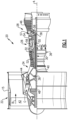
- FIG. 1 schematically illustrates a gas turbine engine 20.
- the gas turbine engine 20 is disclosed herein as a two-spool turbofan that generally incorporates a fan section 22, a compressor section 24, a combustor section 26 and a turbine section 28.
- the fan section 22 drives air along a bypass flow path B in a bypass duct defined within a nacelle 15, and also drives air along a core flow path C for compression and communication into the combustor section 26 then expansion through the turbine section 28.
- FIG. 1 schematically illustrates a gas turbine engine 20.
- the gas turbine engine 20 is disclosed herein as a two-spool turbofan that generally incorporates a fan section 22, a compressor section 24, a combustor section 26 and a turbine section 28.
- the fan section 22 drives air along a bypass flow path B in a bypass duct defined within a nacelle 15, and also drives air along a core flow path C for compression and communication into the combustor section 26 then expansion through the turbine section 28.
- FIG. 1 schematic
- the exemplary engine 20 generally includes a low speed spool 30 and a high speed spool 32 mounted for rotation about an engine central longitudinal axis A relative to an engine static structure 36 via several bearing systems 38. It should be understood that various bearing systems 38 at various locations may alternatively or additionally be provided, and the location of bearing systems 38 may be varied as appropriate to the application.
- the low speed spool 30 generally includes an inner shaft 40 that interconnects, a first (or low) pressure compressor 44 and a first (or low) pressure turbine 46.
- the inner shaft 40 is connected to the fan 42 through a speed change mechanism, which in exemplary gas turbine engine 20 is illustrated as a geared architecture 48 to drive a fan 42 at a lower speed than the low speed spool 30.
- the high speed spool 32 includes an outer shaft 50 that interconnects a second (or high) pressure compressor 52 and a second (or high) pressure turbine 54.
- a combustor 56 is arranged in exemplary gas turbine 20 between the high pressure compressor 52 and the high pressure turbine 54.
- a mid-turbine frame 57 of the engine static structure 36 may be arranged generally between the high pressure turbine 54 and the low pressure turbine 46.
- the mid-turbine frame 57 further supports bearing systems 38 in the turbine section 28.
- the inner shaft 40 and the outer shaft 50 are concentric and rotate via bearing systems 38 about the engine central longitudinal axis A which is colline
- the core airflow is compressed by the low pressure compressor 44 then the high pressure compressor 52, mixed and burned with fuel in the combustor 56, then expanded over the high pressure turbine 54 and low pressure turbine 46.
- the mid-turbine frame 57 includes airfoils 59 which are in the core airflow path C.
- the turbines 46, 54 rotationally drive the respective low speed spool 30 and high speed spool 32 in response to the expansion.
- gear system 48 may be located aft of the low pressure compressor, or aft of the combustor section 26 or even aft of turbine section 28, and fan 42 may be positioned forward or aft of the location of gear system 48.
- the engine 20 in one example is a high-bypass geared aircraft engine.
- the engine 20 bypass ratio is greater than about six, with an example embodiment being greater than about ten
- the geared architecture 48 is an epicyclic gear train, such as a planetary gear system or other gear system, with a gear reduction ratio of greater than about 2.3 and the low pressure turbine 46 has a pressure ratio that is greater than about five.
- the engine 20 bypass ratio is greater than about ten
- the fan diameter is significantly larger than that of the low pressure compressor 44
- the low pressure turbine 46 has a pressure ratio that is greater than about five.
- Low pressure turbine 46 pressure ratio is pressure measured prior to inlet of low pressure turbine 46 as related to the pressure at the outlet of the low pressure turbine 46 prior to an exhaust nozzle.
- the geared architecture 48 may be an epicycle gear train, such as a planetary gear system or other gear system, with a gear reduction ratio of greater than about 2.3:1 and less than about 5:1. It should be understood, however, that the above parameters are only exemplary of one embodiment of a geared architecture engine and that the present invention is applicable to other gas turbine engines including direct drive turbofans.
- the fan section 22 of the engine 20 is designed for a particular flight condition -- typically cruise at about 0.8 Mach and about 35,000 feet (10,668 meters).
- the flight condition of 0.8 Mach and 35,000 ft (10,668 meters), with the engine at its best fuel consumption - also known as "bucket cruise Thrust Specific Fuel Consumption ('TSFC')" - is the industry standard parameter of lbm of fuel being burned divided by lbf of thrust the engine produces at that minimum point.
- "Low fan pressure ratio” is the pressure ratio across the fan blade alone, without a Fan Exit Guide Vane (“FEGV”) system.
- the low fan pressure ratio as disclosed herein according to one non-limiting embodiment is less than about 1.45.
- the "Low corrected fan tip speed” as disclosed herein according to one non-limiting embodiment is less than about 1150 ft / second (350.5 meters/second).
- the ECS is an air system that provides conditioned breathing air to the cabin for aircraft crew and passengers.
- the ECS is comprised of ducts that bleed compressed air off the engine compressor and then direct the air to a series of coolers (e.g. air-to-air coolers and vapor cycle coolers) that condition the air for delivery to an aircraft cabin.
- coolers e.g. air-to-air coolers and vapor cycle coolers
- the fluid lines can include quick-disconnect couplings that allow for attachment and separation of the two systems.
- Figure 2 schematically illustrates an exemplary engine 120 mounted to an aircraft wing 110 via a mount pylon 130.
- air for the ECS is acquired via an electrically driven compressor mounted within the aircraft and bleed air from the turbine engine 120 is not required to drive air to the ECS.
- one or more electric motors 140 drive an electric compressor 142 which provides compressed air to the ECS within the aircraft.
- the electric motors 140 receive generated electricity from a generator 141 within the engine 120.
- the air that is compressed by the electric compressor 142 is sourced from any ambient air source, and is not sourced from within the engine core.
- the utilization of the electric motor 140 creates a new heat load that is not present in conventional aircraft.
- the engine system cooler 150 is positioned in the pylon space 160, which is within the bifurcation and also contains the mount pylon 130.
- the engine system cooler 150 includes a first fluid inlet 152 and a first fluid outlet 154.
- the first fluid inlet 152 connects an internal passage 151 within the cooler 150 to an engine system 121 such that fluid from the engine system 121 can be drawn out of the engine 120 and provided to the internal passage 151.
- the first fluid outlet 154 returns the fluid from the internal passage 151 to the engine 120. In some cases, the fluid is returned to the same engine system 121 that it originated from. In alternative cases, the fluid is returned to a distinct engine system 121 as part of a larger coolant cycle.
- the cooler 150 also includes a second inlet 156 configured to receive an airflow 161 from a fan section 170 of the engine 120.
- the second inlet 156 provides the relatively cold fan air to a second internal passage 153 (or set of second internal passages 153) within the cooler 150.
- a second outlet 158 dumps spent air from the cooler 150 into a bypass flow and allows the spent air to exit the engine 120 structure.
- the cooler 150 is an air-air cooler, and the fluid extracted from the engine 120 is a compressed air from a compressor bleed.
- a cooled cooling air system could utilize this configuration. To provide cooled engine air from a compressor bleed to a turbine on board injection system, a compressor on board injection system, or to any other engine system utilizing cooled cooling air.
- the cooler 150 is an air-oil cooler with the first inlet 152 withdrawing an oil based lubricant/coolant, cooling the oil based lubricant/coolant using the cooler 150, and returning the cooled oil based lubricant/coolant to the engine 120 via the first outlet 154.
- Figure 3 schematically illustrates an alternative example engine 220 mounted to an aircraft wing 210 via a mounting pylon 230.
- Air for the ECS is acquired via an electrically driven compressor mounted within the aircraft and bleed air from the turbine engine 220 is not required to drive air to the ECS.
- one or more electric motors 240 drive an electric compressor 242 which provides compressed air to the ECS within the aircraft.
- the air that is compressed by the electric compressor 242 is sourced from any ambient air source, and is not sourced from within the engine core.
- the utilization of the electric motor 240 creates a new heat load that is not present in conventional aircraft.
- each of the heat exchangers 250, 250', 250" is connected to the same engine system 221.
- each heat exchanger 250, 250', 250" is connected to a distinct engine system 221.
- the heat exchangers 250, 250', 250" each include internal configurations substantially similar to that described above with regards to the heat exchanger 150 and illustrated in Figure 1 , and can be air-air heat exchangers, air-oil heat exchangers, or any combination of the two.
- Positioning an engine system cooler, such as the engine system coolers 150, 250 in the pylon space 160, 260 provides for an improved heat exchanger efficiency, because being positioned in the engine nacelle bifurcation allows the heat exchanger 150, 250 efficiency to benefit from a relatively high source pressure obtained from the ram effect of having the entire inlet 156, 256 duct perimeter be entirely in the fan stream 161.
- engine-mounted heat exchangers that are flush with the engine nacelle include only the outer edge of the inlet duct in the fan stream 161.
- 260 improves the nacelle packaging efficiency by removing bulky components from the engine nacelle.
- Heat exchangers mounted within the engine nacelle are among the physically largest components that fit between the engine and nacelle and inclusion of the heat exchanger within the nacelle may prevent the achievement of the lowest-drag or "ideal' nacelle flowpath. This affect is especially prominent for a high heat-load applications.
- By taking advantage of the pylon packaging instead of under the engine nacelle it may be possible to design more efficient nacelle lines.
Landscapes
- Engineering & Computer Science (AREA)
- Chemical & Material Sciences (AREA)
- Combustion & Propulsion (AREA)
- Mechanical Engineering (AREA)
- General Engineering & Computer Science (AREA)
- Aviation & Aerospace Engineering (AREA)
- Health & Medical Sciences (AREA)
- General Health & Medical Sciences (AREA)
- Pulmonology (AREA)
- Structures Of Non-Positive Displacement Pumps (AREA)
Description
- The present disclosure relates generally to turbine engine heat exchanger configurations, and particularly to a pylon mounted heat exchanger for a gas turbine engine.
- Gas turbine engines, such as those utilized in commercial and military aircraft, include a compressor section that compresses air, a combustor section in which the compressed air is mixed with a fuel and ignited, and a turbine section across which the resultant combustion products are expanded. The expansion of the combustion products drives the turbine section to rotate. As the turbine section is connected to the compressor section via a shaft, the rotation of the turbine section further drives the compressor section to rotate. In some examples, a fan is also connected to the shaft and is driven to rotate via rotation of the turbine as well.
- Within the gas turbine engine, multiple fluids such as air or oil, are actively cooled and provided to other engine components to cool and/or lubricate the other engine components. To achieve the active cooling, the gas turbine engines include heat exchangers within engine core or the engine nacelle.
-
US 2009/188232 A1 discloses a prior art aircraft as set forth in the preamble of claim 1. -
US 2008/028763 A1 discloses a prior art thermal management system with thrust recovery for a gas turbine engine fan nacelle assembly. -
EP 2 085 599 A2 discloses a prior art shared flow thermal management system. -
EP 3 219 620 A1 discloses a prior art engine bleed system with a motorized compressor. - From one aspect, there is provided an aircraft as recited in claim 1.
- There is also provided a method for providing additional heat capacity in a gas turbine engine as recited in claim 7.
- Features of embodiments of the invention are set forth in the dependent claims.
- These and other features of the present invention can be best understood from the following specification and drawings, the following of which is a brief description.
-
-
Figure 1 illustrates a high level schematic view of an exemplary imaging system. -
Figure 2 schematically illustrates an exemplary engine mounted to an aircraft wing via a mounting pylon. -
Figure 3 schematically illustrates an alternative example engine mounted to an aircraft wing via a mounting pylon. -
Figure 1 schematically illustrates agas turbine engine 20. Thegas turbine engine 20 is disclosed herein as a two-spool turbofan that generally incorporates afan section 22, acompressor section 24, a combustor section 26 and aturbine section 28. Thefan section 22 drives air along a bypass flow path B in a bypass duct defined within anacelle 15, and also drives air along a core flow path C for compression and communication into the combustor section 26 then expansion through theturbine section 28. Although depicted as a two-spool turbofan gas turbine engine in the disclosed non-limiting embodiment, it should be understood that the concepts described herein are not limited to use with two-spool turbofans as the teachings may be applied to other types of turbine engines including three-spool architectures. - The
exemplary engine 20 generally includes alow speed spool 30 and ahigh speed spool 32 mounted for rotation about an engine central longitudinal axis A relative to an enginestatic structure 36 viaseveral bearing systems 38. It should be understood thatvarious bearing systems 38 at various locations may alternatively or additionally be provided, and the location ofbearing systems 38 may be varied as appropriate to the application. - The
low speed spool 30 generally includes aninner shaft 40 that interconnects, a first (or low) pressure compressor 44 and a first (or low)pressure turbine 46. Theinner shaft 40 is connected to thefan 42 through a speed change mechanism, which in exemplarygas turbine engine 20 is illustrated as a gearedarchitecture 48 to drive afan 42 at a lower speed than thelow speed spool 30. Thehigh speed spool 32 includes anouter shaft 50 that interconnects a second (or high)pressure compressor 52 and a second (or high)pressure turbine 54. Acombustor 56 is arranged inexemplary gas turbine 20 between thehigh pressure compressor 52 and thehigh pressure turbine 54. Amid-turbine frame 57 of the enginestatic structure 36 may be arranged generally between thehigh pressure turbine 54 and thelow pressure turbine 46. Themid-turbine frame 57 further supports bearingsystems 38 in theturbine section 28. Theinner shaft 40 and theouter shaft 50 are concentric and rotate viabearing systems 38 about the engine central longitudinal axis A which is collinear with their longitudinal axes. - The core airflow is compressed by the low pressure compressor 44 then the
high pressure compressor 52, mixed and burned with fuel in thecombustor 56, then expanded over thehigh pressure turbine 54 andlow pressure turbine 46. Themid-turbine frame 57 includesairfoils 59 which are in the core airflow path C. Theturbines low speed spool 30 andhigh speed spool 32 in response to the expansion. It will be appreciated that each of the positions of thefan section 22,compressor section 24, combustor section 26,turbine section 28, and fandrive gear system 48 may be varied. For example,gear system 48 may be located aft of the low pressure compressor, or aft of the combustor section 26 or even aft ofturbine section 28, andfan 42 may be positioned forward or aft of the location ofgear system 48. - The
engine 20 in one example is a high-bypass geared aircraft engine. In a further example, theengine 20 bypass ratio is greater than about six, with an example embodiment being greater than about ten, the gearedarchitecture 48 is an epicyclic gear train, such as a planetary gear system or other gear system, with a gear reduction ratio of greater than about 2.3 and thelow pressure turbine 46 has a pressure ratio that is greater than about five. In one disclosed embodiment, theengine 20 bypass ratio is greater than about ten, the fan diameter is significantly larger than that of the low pressure compressor 44, and thelow pressure turbine 46 has a pressure ratio that is greater than about five.Low pressure turbine 46 pressure ratio is pressure measured prior to inlet oflow pressure turbine 46 as related to the pressure at the outlet of thelow pressure turbine 46 prior to an exhaust nozzle. The gearedarchitecture 48 may be an epicycle gear train, such as a planetary gear system or other gear system, with a gear reduction ratio of greater than about 2.3:1 and less than about 5:1. It should be understood, however, that the above parameters are only exemplary of one embodiment of a geared architecture engine and that the present invention is applicable to other gas turbine engines including direct drive turbofans. - A significant amount of thrust is provided by the bypass flow B due to the high bypass ratio. The
fan section 22 of theengine 20 is designed for a particular flight condition -- typically cruise at about 0.8 Mach and about 35,000 feet (10,668 meters). The flight condition of 0.8 Mach and 35,000 ft (10,668 meters), with the engine at its best fuel consumption - also known as "bucket cruise Thrust Specific Fuel Consumption ('TSFC')" - is the industry standard parameter of lbm of fuel being burned divided by lbf of thrust the engine produces at that minimum point. "Low fan pressure ratio" is the pressure ratio across the fan blade alone, without a Fan Exit Guide Vane ("FEGV") system. The low fan pressure ratio as disclosed herein according to one non-limiting embodiment is less than about 1.45. "Low corrected fan tip speed" is the actual fan tip speed in ft/sec divided by an industry standard temperature correction of [(Tram °R) / (518.7 °R)]0.5 (where °R = K x 9/5). The "Low corrected fan tip speed" as disclosed herein according to one non-limiting embodiment is less than about 1150 ft / second (350.5 meters/second). - Existing gas turbine engines have moved toward accommodating higher electrical aircraft demands within the aircraft and accessory loads (i.e. electrical loads external to the engine 20) as well as propulsion loads (i.e. electrical loads within the engine 20). Increased power demands require the incorporation of additional generators, motors and other electrical components within the
engine 20. Incorporation of these additional electrical components causes the generation of parasitic heat loads within theengine 20 that must be cooled in order to prevent overheating. In addition, physical space within theengine 20 is at a premium, and inclusion of the electrical components associated with higher electrical aircraft and aircraft engines can stress the space limitations. - One system that has the potential to use more electrical power, and also has a significant impact on aircraft engine performance is an Environmental Cooling System (ECS). The ECS is an air system that provides conditioned breathing air to the cabin for aircraft crew and passengers. In existing aircraft, the ECS is comprised of ducts that bleed compressed air off the engine compressor and then direct the air to a series of coolers (e.g. air-to-air coolers and vapor cycle coolers) that condition the air for delivery to an aircraft cabin.
- Due to the high temperatures of compressor bleed air, existing systems positon one or more of the coolers for the ECS in a space within a mount pylon connecting the
engine 20 to the aircraft body. The mount pylon is located within a bifurcation in the fan stream. Due to the position in the fan stream fan air can be ingested into the embedded cooler within the mount pylon as a cooling source for the bleed air prior to providing the bleed air to the cabin ECS system. In order to facilitate the removal of fluid from the engine core, and the return of the fluid to the engine core, additional integration between the engine and the aircraft is necessary to allow the engine to be removed and repaired. To facilitate this, the fluid lines can include quick-disconnect couplings that allow for attachment and separation of the two systems. - With continued reference to
Figure 1 ,Figure 2 schematically illustrates anexemplary engine 120 mounted to anaircraft wing 110 via amount pylon 130. In the more electric aircraft architecture, air for the ECS is acquired via an electrically driven compressor mounted within the aircraft and bleed air from theturbine engine 120 is not required to drive air to the ECS. In the example architecture, one or moreelectric motors 140 drive anelectric compressor 142 which provides compressed air to the ECS within the aircraft. Theelectric motors 140 receive generated electricity from agenerator 141 within theengine 120. The air that is compressed by theelectric compressor 142 is sourced from any ambient air source, and is not sourced from within the engine core. The utilization of theelectric motor 140 creates a new heat load that is not present in conventional aircraft. - Due to the utilization of the
electric compressor 142, ambient air can be obtained and compressed for utilization in the ECS, and it is not necessary to precool the air, as would be required when pulling air from a compressor bleed. This in turn allows the cooler that is positioned in the pylon space in conventional systems to be replaced with an engine system cooler 150. The engine system cooler 150 is positioned in thepylon space 160, which is within the bifurcation and also contains themount pylon 130. The engine system cooler 150 includes a firstfluid inlet 152 and a firstfluid outlet 154. The firstfluid inlet 152 connects aninternal passage 151 within the cooler 150 to anengine system 121 such that fluid from theengine system 121 can be drawn out of theengine 120 and provided to theinternal passage 151. The firstfluid outlet 154 returns the fluid from theinternal passage 151 to theengine 120. In some cases, the fluid is returned to thesame engine system 121 that it originated from. In alternative cases, the fluid is returned to adistinct engine system 121 as part of a larger coolant cycle. - The cooler 150 also includes a
second inlet 156 configured to receive anairflow 161 from afan section 170 of theengine 120. Thesecond inlet 156 provides the relatively cold fan air to a second internal passage 153 (or set of second internal passages 153) within the cooler 150. Asecond outlet 158 dumps spent air from the cooler 150 into a bypass flow and allows the spent air to exit theengine 120 structure. - In some examples, the cooler 150 is an air-air cooler, and the fluid extracted from the
engine 120 is a compressed air from a compressor bleed. By way of example, a cooled cooling air system could utilize this configuration. To provide cooled engine air from a compressor bleed to a turbine on board injection system, a compressor on board injection system, or to any other engine system utilizing cooled cooling air. - In other examples, the cooler 150 is an air-oil cooler with the
first inlet 152 withdrawing an oil based lubricant/coolant, cooling the oil based lubricant/coolant using the cooler 150, and returning the cooled oil based lubricant/coolant to theengine 120 via thefirst outlet 154. - With continued reference to
Figure 2 , and with like numerals indicating like elements,Figure 3 schematically illustrates analternative example engine 220 mounted to anaircraft wing 210 via a mountingpylon 230. Air for the ECS is acquired via an electrically driven compressor mounted within the aircraft and bleed air from theturbine engine 220 is not required to drive air to the ECS. In the example architecture, one or moreelectric motors 240 drive anelectric compressor 242 which provides compressed air to the ECS within the aircraft. The air that is compressed by theelectric compressor 242 is sourced from any ambient air source, and is not sourced from within the engine core. The utilization of theelectric motor 240 creates a new heat load that is not present in conventional aircraft. - Disposed within the pylon space 260 (within the bifurcation) are three
heat exchangers heat exchangers same engine system 221. In alternative examples, eachheat exchanger distinct engine system 221. Theheat exchangers heat exchanger 150 and illustrated inFigure 1 , and can be air-air heat exchangers, air-oil heat exchangers, or any combination of the two. - Positioning an engine system cooler, such as the
engine system coolers pylon space heat exchanger entire inlet 156, 256 duct perimeter be entirely in thefan stream 161. In contrast, engine-mounted heat exchangers that are flush with the engine nacelle include only the outer edge of the inlet duct in thefan stream 161. By taking advantage of the available ram effect, a higher-efficiency, smaller-sized heat exchanger can be used in thepylon space 160 as compared to heat exchangers that are packaged interior to the engine nacelle. - Further, including the engine system cooler 150, 250 in the
pylon space - Finally, moving the
heat exchangers pylon space heat exchanger pylon space - Although an embodiment of this invention has been disclosed, a worker of ordinary skill in this art would recognize that certain modifications would come within the scope of this invention. For that reason, the following claims should be studied to determine the true scope and content of this invention.
Claims (13)
- An aircraft comprising:at least one gas turbine engine (20; 120; 220) connected to a wing (110; 210) via an engine pylon (130; 230), the gas turbine engine (20; 120; 220) including an engine core having a compressor section (24), a combustor section (26), a turbine section (28), and at least one actively cooled engine system (121; 221);a fan (42; 70) disposed fore of the engine core and rotatably connected to the engine core via a shaft (40), the engine pylon (130; 230) being disposed within a bifurcation that intersects a fan stream (161) of the fan (42; 70) and includes a pylon space (160; 260); andat least one heat exchanger (150; 250; 250'; 250") disposed within the pylon space (160; 260), the heat exchanger (150; 250; 250'; 250") including a first inlet (152) connected to the at least one actively cooled engine system (121; 221) and a first outlet (154) connected to the at least one actively cooled engine system (121; 221),wherein the at least one actively cooled engine system (121; 221) is interior to the engine core,characterised in thatthe aircraft comprises an electric generator (141) connected to said engine core such that rotation of the electric generator (141) is driven by the shaft (40) and an electric compressor (142; 242) is driven by the electric generator (141), wherein the electric compressor (142; 242) is configured to source air from an ambient air source, and wherein a fluid outlet of the electric compressor (142; 242) is fluidly connected to an aircraft cabin environmental cooling system (ECS).
- The aircraft of claim 1, wherein the at least one heat exchanger (150; 250; 250'; 250") includes at most three heat exchangers (250, 250'; 250").
- The aircraft of claim 1 or 2, wherein the at least one heat exchanger (150; 2250; 250'; 250") includes at least one air-oil heat exchanger (150; 250; 250'; 250").
- The aircraft of any preceding claim, wherein the at least one heat exchanger (150; 250; 250'; 250") includes at least one air-air heat exchanger (150; 250; 250'; 250").
- The aircraft of any preceding claim, wherein the at least one heat exchanger (150; 250; 250'; 250") includes a second inlet (156) disposed in the fan stream (161) and configured to ingest fan stream air.
- The aircraft of any preceding claim, wherein the at least one heat exchanger (150; 250; 250'; 250") includes a second outlet (158) configured to exhaust spent fan stream air to the fan stream.
- A method for providing additional heat capacity in a gas turbine engine (20; 120; 220) comprising:removing a cooling fluid from at least one engine system (121; 221) within a gas turbine engine nacelle (15);providing the removed cooling fluid to a heat exchanger (150; 250; 250'; 250") disposed within a pylon space (160; 260) of a bifurcation that intersects a fan stream (161) and also contains a pylon (130; 230) connecting the gas turbine engine nacelle (15) to an aircraft wing (110; 210);cooling the cooling fluid within the heat exchanger (150; 250; 250'; 250");returning the cooling fluid to the at least one engine system (121; 221);providing compressed air to a cabin environmental cooling system (ECS) from an electric compressor (142; 242); andpowering the electric compressor (142; 242) via an electric generator (141), wherein the electric generator (141) is driven by a shaft (40) within the gas turbine engine nacelle (15), wherein the electric compressor (142; 242) sources air from an ambient air source, and wherein a fluid outlet of the electric compressor (142; 242) is fluidly connected to an aircraft cabin environmental cooling system (ECS).
- The method of claim 7, wherein removing the cooling fluid from at least one engine system (221) and returning the cooling fluid to the at least one engine system (221) comprise removing the cooling fluid from a single engine system (221) in the at least one engine system and returning the cooling fluid to the single engine system (221) in the at least one engine system (221).
- The method of claim 7, wherein removing the cooling fluid from at least one engine system (121) and returning the cooling fluid to the at least one engine system (121) comprise removing the cooling fluid from a first engine system (121) in the at least one engine system (121) and returning the cooling fluid to a second engine system (121) in the at least one engine system (121), wherein the first engine system (121) and the second engine system (121) are part of a single coolant cycle.
- The method of any of claims 7 to 9, wherein providing the removed cooling fluid to a heat exchanger (250; 250'; 250") comprises providing the cooling fluid to three heat exchangers (250; 250'; 250").
- The method of claim 9, wherein cooling the cooling fluid within the heat exchanger (150; 250; 250'; 250") comprises ingesting fan stream air (161) along a cooling flowpath (153) within the heat exchanger (150; 250; 250'; 250") and passing the cooling fluid through the heat exchanger (150; 250; 250'; 250") along a circuitous route (151).
- The method of any of claims 7 to 11, wherein the heat exchanger (150; 250; 250'; 250") is an air-air heat exchanger (150; 250; 250'; 250").
- The method of any of claims 7 to 11, wherein the heat exchanger (150; 250; 250'; 250") is an air-oil heat exchanger (150; 250; 250'; 250").
Applications Claiming Priority (2)
| Application Number | Priority Date | Filing Date | Title |
|---|---|---|---|
| US201962822315P | 2019-03-22 | 2019-03-22 | |
| US16/744,508 US20200300164A1 (en) | 2019-03-22 | 2020-01-16 | Turbine engine configuration including pylon mounted heat exchanger |
Publications (2)
| Publication Number | Publication Date |
|---|---|
| EP3712404A1 EP3712404A1 (en) | 2020-09-23 |
| EP3712404B1 true EP3712404B1 (en) | 2024-09-18 |
Family
ID=69953851
Family Applications (1)
| Application Number | Title | Priority Date | Filing Date |
|---|---|---|---|
| EP20164843.3A Active EP3712404B1 (en) | 2019-03-22 | 2020-03-23 | Turbine engine configuration including pylon mounted heat exchanger |
Country Status (2)
| Country | Link |
|---|---|
| US (1) | US20200300164A1 (en) |
| EP (1) | EP3712404B1 (en) |
Families Citing this family (12)
| Publication number | Priority date | Publication date | Assignee | Title |
|---|---|---|---|---|
| FR3077060A1 (en) * | 2018-01-24 | 2019-07-26 | Airbus Operations | AIRCRAFT MAT COMPRISING A COAXIAL THERMAL EXCHANGER |
| US11035251B2 (en) * | 2019-09-26 | 2021-06-15 | General Electric Company | Stator temperature control system for a gas turbine engine |
| FR3128443A1 (en) * | 2021-10-25 | 2023-04-28 | Airbus Operations (S.A.S.) | Aircraft propulsion assembly comprising a plate heat exchanger, of hexagonal longitudinal section, positioned in a bifurcation |
| FR3133367B1 (en) * | 2022-03-11 | 2024-08-23 | Safran Aircraft Engines | AERONAUTICAL PROPELLER |
| GB202218535D0 (en) * | 2022-12-09 | 2023-01-25 | Rolls Royce Plc | A propulsion system comprising a heat exchanger |
| WO2024217634A1 (en) * | 2023-04-21 | 2024-10-24 | MTU Aero Engines AG | Aircraft drive and method for operating an aircraft drive |
| US12618363B2 (en) | 2023-07-18 | 2026-05-05 | Rtx Corporation | Bifurcation air scoop for gas turbine engine |
| FR3156486A1 (en) * | 2023-12-08 | 2025-06-13 | Airbus Operations (S.A.S.) | PROPULSION UNIT OF AN AIRCRAFT COMPRISING A FLUID COOLING CIRCUIT WITH QUICK NACELLE/ENGINE COUPLINGS AND AIRCRAFT EQUIPPED WITH SUCH AN ASSEMBLY |
| US20250236386A1 (en) * | 2024-01-19 | 2025-07-24 | Pratt & Whitney Canada Corp. | Rotorcraft with powerplant exhaust sound attenuation |
| US20250236408A1 (en) * | 2024-01-22 | 2025-07-24 | Rtx Corporation | Framed heat exchanger for aircraft propulsion system |
| US12372029B1 (en) * | 2024-04-24 | 2025-07-29 | General Electric Company | Gas turbine engine having cooling systems |
| US20250354519A1 (en) * | 2024-04-24 | 2025-11-20 | General Electric Company | Gas turbine engine having cooling systems |
Family Cites Families (4)
| Publication number | Priority date | Publication date | Assignee | Title |
|---|---|---|---|---|
| US20080028763A1 (en) * | 2006-08-03 | 2008-02-07 | United Technologies Corporation | Thermal management system with thrust recovery for a gas turbine engine fan nacelle assembly |
| US8826641B2 (en) * | 2008-01-28 | 2014-09-09 | United Technologies Corporation | Thermal management system integrated pylon |
| US9234481B2 (en) * | 2008-01-25 | 2016-01-12 | United Technologies Corporation | Shared flow thermal management system |
| US11473497B2 (en) * | 2016-03-15 | 2022-10-18 | Hamilton Sundstrand Corporation | Engine bleed system with motorized compressor |
-
2020
- 2020-01-16 US US16/744,508 patent/US20200300164A1/en not_active Abandoned
- 2020-03-23 EP EP20164843.3A patent/EP3712404B1/en active Active
Also Published As
| Publication number | Publication date |
|---|---|
| EP3712404A1 (en) | 2020-09-23 |
| US20200300164A1 (en) | 2020-09-24 |
Similar Documents
| Publication | Publication Date | Title |
|---|---|---|
| EP3712404A1 (en) | Turbine engine configuration including pylon mounted heat exchanger | |
| US11815024B2 (en) | Thermal management system | |
| US11286853B2 (en) | Cooling system | |
| EP4368817B1 (en) | Cooling system for power cables in a gas turbine engine | |
| EP2981697B1 (en) | Air oil cooler airflow augmentation system and corresponding method | |
| US9863318B2 (en) | Thermal management system for gas turbine engine | |
| US9945325B2 (en) | Integrated heat exchangers for low fan pressure ratio geared turbofan | |
| CA2936632C (en) | Integral oil tank heat exchanger | |
| US11795837B2 (en) | Embedded electric machine | |
| EP2971664B1 (en) | Geared turbofan engine and cooling method thereof | |
| EP2584168A2 (en) | Integrated thermal system for a gas turbine engine | |
| EP3786428B1 (en) | Oil tank for geared turbofan engine | |
| EP3428427A1 (en) | Gas turbine engine with air-oil cooler oil tank | |
| EP2085599A2 (en) | Shared flow thermal management system | |
| US11674438B1 (en) | Thermal management system | |
| US12270342B1 (en) | Thermal management system for an engine | |
| EP4394168A1 (en) | Nose cone generator | |
| US12560119B1 (en) | Working fluid system for aircraft powerplant |
Legal Events
| Date | Code | Title | Description |
|---|---|---|---|
| PUAI | Public reference made under article 153(3) epc to a published international application that has entered the european phase |
Free format text: ORIGINAL CODE: 0009012 |
|
| STAA | Information on the status of an ep patent application or granted ep patent |
Free format text: STATUS: THE APPLICATION HAS BEEN PUBLISHED |
|
| AK | Designated contracting states |
Kind code of ref document: A1 Designated state(s): AL AT BE BG CH CY CZ DE DK EE ES FI FR GB GR HR HU IE IS IT LI LT LU LV MC MK MT NL NO PL PT RO RS SE SI SK SM TR |
|
| AX | Request for extension of the european patent |
Extension state: BA ME |
|
| RAP1 | Party data changed (applicant data changed or rights of an application transferred) |
Owner name: RAYTHEON TECHNOLOGIES CORPORATION |
|
| STAA | Information on the status of an ep patent application or granted ep patent |
Free format text: STATUS: REQUEST FOR EXAMINATION WAS MADE |
|
| 17P | Request for examination filed |
Effective date: 20210323 |
|
| RBV | Designated contracting states (corrected) |
Designated state(s): AL AT BE BG CH CY CZ DE DK EE ES FI FR GB GR HR HU IE IS IT LI LT LU LV MC MK MT NL NO PL PT RO RS SE SI SK SM TR |
|
| STAA | Information on the status of an ep patent application or granted ep patent |
Free format text: STATUS: EXAMINATION IS IN PROGRESS |
|
| 17Q | First examination report despatched |
Effective date: 20221006 |
|
| RAP3 | Party data changed (applicant data changed or rights of an application transferred) |
Owner name: RTX CORPORATION |
|
| GRAP | Despatch of communication of intention to grant a patent |
Free format text: ORIGINAL CODE: EPIDOSNIGR1 |
|
| STAA | Information on the status of an ep patent application or granted ep patent |
Free format text: STATUS: GRANT OF PATENT IS INTENDED |
|
| INTG | Intention to grant announced |
Effective date: 20240412 |
|
| GRAS | Grant fee paid |
Free format text: ORIGINAL CODE: EPIDOSNIGR3 |
|
| GRAA | (expected) grant |
Free format text: ORIGINAL CODE: 0009210 |
|
| STAA | Information on the status of an ep patent application or granted ep patent |
Free format text: STATUS: THE PATENT HAS BEEN GRANTED |
|
| AK | Designated contracting states |
Kind code of ref document: B1 Designated state(s): AL AT BE BG CH CY CZ DE DK EE ES FI FR GB GR HR HU IE IS IT LI LT LU LV MC MK MT NL NO PL PT RO RS SE SI SK SM TR |
|
| REG | Reference to a national code |
Ref country code: GB Ref legal event code: FG4D |
|
| REG | Reference to a national code |
Ref country code: CH Ref legal event code: EP |
|
| REG | Reference to a national code |
Ref country code: IE Ref legal event code: FG4D |
|
| REG | Reference to a national code |
Ref country code: DE Ref legal event code: R096 Ref document number: 602020037791 Country of ref document: DE |
|
| REG | Reference to a national code |
Ref country code: LT Ref legal event code: MG9D |
|
| PG25 | Lapsed in a contracting state [announced via postgrant information from national office to epo] |
Ref country code: NO Free format text: LAPSE BECAUSE OF FAILURE TO SUBMIT A TRANSLATION OF THE DESCRIPTION OR TO PAY THE FEE WITHIN THE PRESCRIBED TIME-LIMIT Effective date: 20241218 |
|
| PG25 | Lapsed in a contracting state [announced via postgrant information from national office to epo] |
Ref country code: GR Free format text: LAPSE BECAUSE OF FAILURE TO SUBMIT A TRANSLATION OF THE DESCRIPTION OR TO PAY THE FEE WITHIN THE PRESCRIBED TIME-LIMIT Effective date: 20241219 Ref country code: FI Free format text: LAPSE BECAUSE OF FAILURE TO SUBMIT A TRANSLATION OF THE DESCRIPTION OR TO PAY THE FEE WITHIN THE PRESCRIBED TIME-LIMIT Effective date: 20240918 |
|
| PG25 | Lapsed in a contracting state [announced via postgrant information from national office to epo] |
Ref country code: BG Free format text: LAPSE BECAUSE OF FAILURE TO SUBMIT A TRANSLATION OF THE DESCRIPTION OR TO PAY THE FEE WITHIN THE PRESCRIBED TIME-LIMIT Effective date: 20240918 |
|
| PG25 | Lapsed in a contracting state [announced via postgrant information from national office to epo] |
Ref country code: LV Free format text: LAPSE BECAUSE OF FAILURE TO SUBMIT A TRANSLATION OF THE DESCRIPTION OR TO PAY THE FEE WITHIN THE PRESCRIBED TIME-LIMIT Effective date: 20240918 |
|
| PG25 | Lapsed in a contracting state [announced via postgrant information from national office to epo] |
Ref country code: HR Free format text: LAPSE BECAUSE OF FAILURE TO SUBMIT A TRANSLATION OF THE DESCRIPTION OR TO PAY THE FEE WITHIN THE PRESCRIBED TIME-LIMIT Effective date: 20240918 |
|
| REG | Reference to a national code |
Ref country code: NL Ref legal event code: MP Effective date: 20240918 |
|
| PG25 | Lapsed in a contracting state [announced via postgrant information from national office to epo] |
Ref country code: RS Free format text: LAPSE BECAUSE OF FAILURE TO SUBMIT A TRANSLATION OF THE DESCRIPTION OR TO PAY THE FEE WITHIN THE PRESCRIBED TIME-LIMIT Effective date: 20241218 |
|
| PG25 | Lapsed in a contracting state [announced via postgrant information from national office to epo] |
Ref country code: RS Free format text: LAPSE BECAUSE OF FAILURE TO SUBMIT A TRANSLATION OF THE DESCRIPTION OR TO PAY THE FEE WITHIN THE PRESCRIBED TIME-LIMIT Effective date: 20241218 Ref country code: NO Free format text: LAPSE BECAUSE OF FAILURE TO SUBMIT A TRANSLATION OF THE DESCRIPTION OR TO PAY THE FEE WITHIN THE PRESCRIBED TIME-LIMIT Effective date: 20241218 Ref country code: LV Free format text: LAPSE BECAUSE OF FAILURE TO SUBMIT A TRANSLATION OF THE DESCRIPTION OR TO PAY THE FEE WITHIN THE PRESCRIBED TIME-LIMIT Effective date: 20240918 Ref country code: HR Free format text: LAPSE BECAUSE OF FAILURE TO SUBMIT A TRANSLATION OF THE DESCRIPTION OR TO PAY THE FEE WITHIN THE PRESCRIBED TIME-LIMIT Effective date: 20240918 Ref country code: GR Free format text: LAPSE BECAUSE OF FAILURE TO SUBMIT A TRANSLATION OF THE DESCRIPTION OR TO PAY THE FEE WITHIN THE PRESCRIBED TIME-LIMIT Effective date: 20241219 Ref country code: FI Free format text: LAPSE BECAUSE OF FAILURE TO SUBMIT A TRANSLATION OF THE DESCRIPTION OR TO PAY THE FEE WITHIN THE PRESCRIBED TIME-LIMIT Effective date: 20240918 Ref country code: BG Free format text: LAPSE BECAUSE OF FAILURE TO SUBMIT A TRANSLATION OF THE DESCRIPTION OR TO PAY THE FEE WITHIN THE PRESCRIBED TIME-LIMIT Effective date: 20240918 |
|
| REG | Reference to a national code |
Ref country code: AT Ref legal event code: MK05 Ref document number: 1724863 Country of ref document: AT Kind code of ref document: T Effective date: 20240918 |
|
| PG25 | Lapsed in a contracting state [announced via postgrant information from national office to epo] |
Ref country code: NL Free format text: LAPSE BECAUSE OF FAILURE TO SUBMIT A TRANSLATION OF THE DESCRIPTION OR TO PAY THE FEE WITHIN THE PRESCRIBED TIME-LIMIT Effective date: 20240918 |
|
| PG25 | Lapsed in a contracting state [announced via postgrant information from national office to epo] |
Ref country code: PT Free format text: LAPSE BECAUSE OF FAILURE TO SUBMIT A TRANSLATION OF THE DESCRIPTION OR TO PAY THE FEE WITHIN THE PRESCRIBED TIME-LIMIT Effective date: 20250120 Ref country code: IS Free format text: LAPSE BECAUSE OF FAILURE TO SUBMIT A TRANSLATION OF THE DESCRIPTION OR TO PAY THE FEE WITHIN THE PRESCRIBED TIME-LIMIT Effective date: 20250118 |
|
| PG25 | Lapsed in a contracting state [announced via postgrant information from national office to epo] |
Ref country code: SM Free format text: LAPSE BECAUSE OF FAILURE TO SUBMIT A TRANSLATION OF THE DESCRIPTION OR TO PAY THE FEE WITHIN THE PRESCRIBED TIME-LIMIT Effective date: 20240918 Ref country code: RO Free format text: LAPSE BECAUSE OF FAILURE TO SUBMIT A TRANSLATION OF THE DESCRIPTION OR TO PAY THE FEE WITHIN THE PRESCRIBED TIME-LIMIT Effective date: 20240918 |
|
| PG25 | Lapsed in a contracting state [announced via postgrant information from national office to epo] |
Ref country code: ES Free format text: LAPSE BECAUSE OF FAILURE TO SUBMIT A TRANSLATION OF THE DESCRIPTION OR TO PAY THE FEE WITHIN THE PRESCRIBED TIME-LIMIT Effective date: 20240918 |
|
| PG25 | Lapsed in a contracting state [announced via postgrant information from national office to epo] |
Ref country code: AT Free format text: LAPSE BECAUSE OF FAILURE TO SUBMIT A TRANSLATION OF THE DESCRIPTION OR TO PAY THE FEE WITHIN THE PRESCRIBED TIME-LIMIT Effective date: 20240918 Ref country code: EE Free format text: LAPSE BECAUSE OF FAILURE TO SUBMIT A TRANSLATION OF THE DESCRIPTION OR TO PAY THE FEE WITHIN THE PRESCRIBED TIME-LIMIT Effective date: 20240918 |
|
| PG25 | Lapsed in a contracting state [announced via postgrant information from national office to epo] |
Ref country code: CZ Free format text: LAPSE BECAUSE OF FAILURE TO SUBMIT A TRANSLATION OF THE DESCRIPTION OR TO PAY THE FEE WITHIN THE PRESCRIBED TIME-LIMIT Effective date: 20240918 Ref country code: PL Free format text: LAPSE BECAUSE OF FAILURE TO SUBMIT A TRANSLATION OF THE DESCRIPTION OR TO PAY THE FEE WITHIN THE PRESCRIBED TIME-LIMIT Effective date: 20240918 |
|
| PG25 | Lapsed in a contracting state [announced via postgrant information from national office to epo] |
Ref country code: SK Free format text: LAPSE BECAUSE OF FAILURE TO SUBMIT A TRANSLATION OF THE DESCRIPTION OR TO PAY THE FEE WITHIN THE PRESCRIBED TIME-LIMIT Effective date: 20240918 Ref country code: IT Free format text: LAPSE BECAUSE OF FAILURE TO SUBMIT A TRANSLATION OF THE DESCRIPTION OR TO PAY THE FEE WITHIN THE PRESCRIBED TIME-LIMIT Effective date: 20240918 |
|
| REG | Reference to a national code |
Ref country code: DE Ref legal event code: R097 Ref document number: 602020037791 Country of ref document: DE |
|
| PG25 | Lapsed in a contracting state [announced via postgrant information from national office to epo] |
Ref country code: DK Free format text: LAPSE BECAUSE OF FAILURE TO SUBMIT A TRANSLATION OF THE DESCRIPTION OR TO PAY THE FEE WITHIN THE PRESCRIBED TIME-LIMIT Effective date: 20240918 |
|
| PLBE | No opposition filed within time limit |
Free format text: ORIGINAL CODE: 0009261 |
|
| STAA | Information on the status of an ep patent application or granted ep patent |
Free format text: STATUS: NO OPPOSITION FILED WITHIN TIME LIMIT |
|
| 26N | No opposition filed |
Effective date: 20250619 |
|
| PG25 | Lapsed in a contracting state [announced via postgrant information from national office to epo] |
Ref country code: SE Free format text: LAPSE BECAUSE OF FAILURE TO SUBMIT A TRANSLATION OF THE DESCRIPTION OR TO PAY THE FEE WITHIN THE PRESCRIBED TIME-LIMIT Effective date: 20240918 |
|
| PG25 | Lapsed in a contracting state [announced via postgrant information from national office to epo] |
Ref country code: MC Free format text: LAPSE BECAUSE OF FAILURE TO SUBMIT A TRANSLATION OF THE DESCRIPTION OR TO PAY THE FEE WITHIN THE PRESCRIBED TIME-LIMIT Effective date: 20240918 |
|
| REG | Reference to a national code |
Ref country code: CH Ref legal event code: H13 Free format text: ST27 STATUS EVENT CODE: U-0-0-H10-H13 (AS PROVIDED BY THE NATIONAL OFFICE) Effective date: 20251023 |
|
| PG25 | Lapsed in a contracting state [announced via postgrant information from national office to epo] |
Ref country code: LU Free format text: LAPSE BECAUSE OF NON-PAYMENT OF DUE FEES Effective date: 20250323 |
|
| REG | Reference to a national code |
Ref country code: BE Ref legal event code: MM Effective date: 20250331 |
|
| PG25 | Lapsed in a contracting state [announced via postgrant information from national office to epo] |
Ref country code: BE Free format text: LAPSE BECAUSE OF NON-PAYMENT OF DUE FEES Effective date: 20250331 |
|
| PG25 | Lapsed in a contracting state [announced via postgrant information from national office to epo] |
Ref country code: CH Free format text: LAPSE BECAUSE OF NON-PAYMENT OF DUE FEES Effective date: 20250331 |
|
| PG25 | Lapsed in a contracting state [announced via postgrant information from national office to epo] |
Ref country code: IE Free format text: LAPSE BECAUSE OF NON-PAYMENT OF DUE FEES Effective date: 20250323 |
|
| PGFP | Annual fee paid to national office [announced via postgrant information from national office to epo] |
Ref country code: GB Payment date: 20260219 Year of fee payment: 7 |
|
| PGFP | Annual fee paid to national office [announced via postgrant information from national office to epo] |
Ref country code: DE Payment date: 20260219 Year of fee payment: 7 |
|
| PGFP | Annual fee paid to national office [announced via postgrant information from national office to epo] |
Ref country code: FR Payment date: 20260219 Year of fee payment: 7 |