EP3712395B1 - Seal assembly for a gas turbine engine - Google Patents
Seal assembly for a gas turbine engine Download PDFInfo
- Publication number
- EP3712395B1 EP3712395B1 EP20163752.7A EP20163752A EP3712395B1 EP 3712395 B1 EP3712395 B1 EP 3712395B1 EP 20163752 A EP20163752 A EP 20163752A EP 3712395 B1 EP3712395 B1 EP 3712395B1
- Authority
- EP
- European Patent Office
- Prior art keywords
- seal
- bearing
- port
- bearing housing
- seal member
- Prior art date
- Legal status (The legal status is an assumption and is not a legal conclusion. Google has not performed a legal analysis and makes no representation as to the accuracy of the status listed.)
- Active
Links
Images

Classifications
-
- F—MECHANICAL ENGINEERING; LIGHTING; HEATING; WEAPONS; BLASTING
- F01—MACHINES OR ENGINES IN GENERAL; ENGINE PLANTS IN GENERAL; STEAM ENGINES
- F01D—NON-POSITIVE DISPLACEMENT MACHINES OR ENGINES, e.g. STEAM TURBINES
- F01D25/00—Component parts, details, or accessories, not provided for in, or of interest apart from, other groups
- F01D25/16—Arrangement of bearings; Supporting or mounting bearings in casings
-
- F—MECHANICAL ENGINEERING; LIGHTING; HEATING; WEAPONS; BLASTING
- F01—MACHINES OR ENGINES IN GENERAL; ENGINE PLANTS IN GENERAL; STEAM ENGINES
- F01D—NON-POSITIVE DISPLACEMENT MACHINES OR ENGINES, e.g. STEAM TURBINES
- F01D25/00—Component parts, details, or accessories, not provided for in, or of interest apart from, other groups
- F01D25/18—Lubricating arrangements
- F01D25/183—Sealing means
-
- F—MECHANICAL ENGINEERING; LIGHTING; HEATING; WEAPONS; BLASTING
- F01—MACHINES OR ENGINES IN GENERAL; ENGINE PLANTS IN GENERAL; STEAM ENGINES
- F01D—NON-POSITIVE DISPLACEMENT MACHINES OR ENGINES, e.g. STEAM TURBINES
- F01D11/00—Preventing or minimising internal leakage of working-fluid, e.g. between stages
- F01D11/003—Preventing or minimising internal leakage of working-fluid, e.g. between stages by packing rings; Mechanical seals
-
- F—MECHANICAL ENGINEERING; LIGHTING; HEATING; WEAPONS; BLASTING
- F01—MACHINES OR ENGINES IN GENERAL; ENGINE PLANTS IN GENERAL; STEAM ENGINES
- F01D—NON-POSITIVE DISPLACEMENT MACHINES OR ENGINES, e.g. STEAM TURBINES
- F01D25/00—Component parts, details, or accessories, not provided for in, or of interest apart from, other groups
- F01D25/08—Cooling; Heating; Heat-insulation
- F01D25/12—Cooling
- F01D25/125—Cooling of bearings
-
- F—MECHANICAL ENGINEERING; LIGHTING; HEATING; WEAPONS; BLASTING
- F01—MACHINES OR ENGINES IN GENERAL; ENGINE PLANTS IN GENERAL; STEAM ENGINES
- F01D—NON-POSITIVE DISPLACEMENT MACHINES OR ENGINES, e.g. STEAM TURBINES
- F01D25/00—Component parts, details, or accessories, not provided for in, or of interest apart from, other groups
- F01D25/24—Casings; Casing parts, e.g. diaphragms, casing fastenings
-
- F—MECHANICAL ENGINEERING; LIGHTING; HEATING; WEAPONS; BLASTING
- F02—COMBUSTION ENGINES; HOT-GAS OR COMBUSTION-PRODUCT ENGINE PLANTS
- F02C—GAS-TURBINE PLANTS; AIR INTAKES FOR JET-PROPULSION PLANTS; CONTROLLING FUEL SUPPLY IN AIR-BREATHING JET-PROPULSION PLANTS
- F02C7/00—Features, components parts, details or accessories, not provided for in, or of interest apart form groups F02C1/00 - F02C6/00; Air intakes for jet-propulsion plants
- F02C7/20—Mounting or supporting of plant; Accommodating heat expansion or creep
-
- F—MECHANICAL ENGINEERING; LIGHTING; HEATING; WEAPONS; BLASTING
- F02—COMBUSTION ENGINES; HOT-GAS OR COMBUSTION-PRODUCT ENGINE PLANTS
- F02C—GAS-TURBINE PLANTS; AIR INTAKES FOR JET-PROPULSION PLANTS; CONTROLLING FUEL SUPPLY IN AIR-BREATHING JET-PROPULSION PLANTS
- F02C7/00—Features, components parts, details or accessories, not provided for in, or of interest apart form groups F02C1/00 - F02C6/00; Air intakes for jet-propulsion plants
- F02C7/28—Arrangement of seals
-
- F—MECHANICAL ENGINEERING; LIGHTING; HEATING; WEAPONS; BLASTING
- F05—INDEXING SCHEMES RELATING TO ENGINES OR PUMPS IN VARIOUS SUBCLASSES OF CLASSES F01-F04
- F05D—INDEXING SCHEME FOR ASPECTS RELATING TO NON-POSITIVE-DISPLACEMENT MACHINES OR ENGINES, GAS-TURBINES OR JET-PROPULSION PLANTS
- F05D2220/00—Application
- F05D2220/30—Application in turbines
- F05D2220/32—Application in turbines in gas turbines
-
- F—MECHANICAL ENGINEERING; LIGHTING; HEATING; WEAPONS; BLASTING
- F16—ENGINEERING ELEMENTS AND UNITS; GENERAL MEASURES FOR PRODUCING AND MAINTAINING EFFECTIVE FUNCTIONING OF MACHINES OR INSTALLATIONS; THERMAL INSULATION IN GENERAL
- F16J—PISTONS; CYLINDERS; SEALINGS
- F16J15/00—Sealings
- F16J15/16—Sealings between relatively-moving surfaces
- F16J15/164—Sealings between relatively-moving surfaces the sealing action depending on movements; pressure difference, temperature or presence of leaking fluid
-
- F—MECHANICAL ENGINEERING; LIGHTING; HEATING; WEAPONS; BLASTING
- F16—ENGINEERING ELEMENTS AND UNITS; GENERAL MEASURES FOR PRODUCING AND MAINTAINING EFFECTIVE FUNCTIONING OF MACHINES OR INSTALLATIONS; THERMAL INSULATION IN GENERAL
- F16J—PISTONS; CYLINDERS; SEALINGS
- F16J15/00—Sealings
- F16J15/16—Sealings between relatively-moving surfaces
- F16J15/34—Sealings between relatively-moving surfaces with slip-ring pressed against a more or less radial face on one member
- F16J15/3404—Sealings between relatively-moving surfaces with slip-ring pressed against a more or less radial face on one member and characterised by parts or details relating to lubrication, cooling or venting of the seal
-
- F—MECHANICAL ENGINEERING; LIGHTING; HEATING; WEAPONS; BLASTING
- F16—ENGINEERING ELEMENTS AND UNITS; GENERAL MEASURES FOR PRODUCING AND MAINTAINING EFFECTIVE FUNCTIONING OF MACHINES OR INSTALLATIONS; THERMAL INSULATION IN GENERAL
- F16J—PISTONS; CYLINDERS; SEALINGS
- F16J15/00—Sealings
- F16J15/44—Free-space packings
- F16J15/447—Labyrinth packings
- F16J15/4472—Labyrinth packings with axial path
Definitions
- This disclosure relates to sealing for a gas turbine engine, including sealing of bearing compartments.
- Gas turbine engines typically include a fan delivering air into a low pressure compressor section.
- the air is compressed in the low pressure compressor section, and passed into a high pressure compressor section.
- From the high pressure compressor section the air is introduced into a combustor section where it is mixed with fuel and ignited. Products of this combustion pass downstream over a high pressure turbine section, and then a low pressure turbine section to extract energy for driving the fan.
- Bearing compartments typically receive fluid for cooling and lubricating one or more bearings.
- the bearing compartment may include seals that fluidly separate the bearing compartment from adjacent cavities.
- EP 3421737 A1 describes a bearing assembly including a bearing situated in a bearing compartment and a seal assembly that defines the bearing compartment.
- US 2013/241153 A1 describes a windback device for a circumferential seal within a turbine engine.
- EP 2157289 A2 describes a rotating seal for a gas turbine engine.
- seal assembly for a gas turbine engine as recited in claim 1.
- the seal member may include a seal body that has a plurality of helical teeth that are interdigitated with the plurality of helical grooves, and each of the helical teeth may have a radial face defining an outer diameter of the seal body.
- the seal member may include a seal body that has a first vertical face and a second vertical face axially spaced apart from the first vertical face, and each one of the helical grooves may extend in the axial direction along the outer diameter of the seal body from the first vertical face to the second vertical face.
- the projection of the passage axis of the drain passage may be oriented to intersect a vertical face of the seal member and inlets of the helical grooves.
- the seal assembly may include at least one secondary seal extending outwardly from the seal carrier to establish a second sealing relationship with a second seal land defined along the inner diameter of the bearing housing.
- the seal member may establish the first sealing relationship along a fluid passage at a position between the bearing compartment and the at least one secondary seal.
- the seal member and the at least secondary seal may be integrally formed with the seal carrier.
- the drain passage may extend between a first port and a second port.
- the first port may be the drain port and the second port may be defined along the inner diameter of the bearing housing at a position axially between the at least one secondary seal and the seal member to fluidly couple the drain passage and the fluid passage.
- the drain passage may define a passage axis that is sloped towards the seal member.
- the seal member may include a seal body defining a plurality of helical teeth that are interdigitated with the plurality of helical grooves, and each of the helical teeth may have a radial face defining an outer diameter of the seal body.
- the seal assembly may include first and second knife edge seals that extend outwardly from the seal carrier to establish second and third sealing relationships with second and third seal lands defined by the bearing housing.
- the drain passage of the seal assembly or the gas turbine engine may extend between a first port and a second port.
- the first port may be the drain port, and the second port may be defined along an inner diameter of the bearing housing, the inner diameter defining the first seal land.
- First and second knife edge seals may extend outwardly from the seal carrier to establish first and second sealing relationships with second and third seal lands defined along the inner diameter of the bearing housing.
- the seal member may establish the first sealing relationship along a fluid passage at a position between the bearing compartment and the first and second knife edge seals, and the second port may be defined along the fluid passage between the seal member and the first and second knife edge seals.
- the seal member and the first and second knife edge seals may be integrally formed with the seal carrier.
- the bearing compartment may include a bearing that supports a rotatable shaft.
- the seal member may be mounted to the shaft, and the rotating step may include rotating the shaft about the longitudinal axis.
- the method may include communicating lubricant from the fluid passage to the drain passage.
- the drain passage may extend between a first port and a second port.
- the first port may be the drain port and the second port may be defined along an inner diameter of the bearing housing.
- the rotating step may include establishing a second sealing relationship between the bearing housing and at least one knife edge seal.
- the seal member and the at least one knife edge seal may extend outwardly from a seal carrier.
- the seal carrier may be fixedly attached to an outer periphery of the shaft.
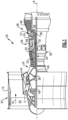
- FIG. 1 schematically illustrates a gas turbine engine 20.
- the gas turbine engine 20 is disclosed herein as a two-spool turbofan that generally incorporates a fan section 22, a compressor section 24, a combustor section 26 and a turbine section 28.
- the fan section 22 drives air along a bypass flow path B in a bypass duct defined within a nacelle 15, and also drives air along a core flow path C for compression and communication into the combustor section 26 then expansion through the turbine section 28.
- FIG. 1 schematically illustrates a gas turbine engine 20.
- the gas turbine engine 20 is disclosed herein as a two-spool turbofan that generally incorporates a fan section 22, a compressor section 24, a combustor section 26 and a turbine section 28.
- the fan section 22 drives air along a bypass flow path B in a bypass duct defined within a nacelle 15, and also drives air along a core flow path C for compression and communication into the combustor section 26 then expansion through the turbine section 28.
- FIG. 1 schematic
- the exemplary engine 20 generally includes a low speed spool 30 and a high speed spool 32 mounted for rotation about an engine central longitudinal axis A relative to an engine static structure 36 via several bearing systems 38. It should be understood that various bearing systems 38 at various locations may alternatively or additionally be provided, and the location of bearing systems 38 may be varied as appropriate to the application.
- the low speed spool 30 generally includes an inner shaft 40 that interconnects, a first (or low) pressure compressor 44 and a first (or low) pressure turbine 46.
- the inner shaft 40 is connected to the fan 42 through a speed change mechanism, which in exemplary gas turbine engine 20 is illustrated as a geared architecture 48 to drive a fan 42 at a lower speed than the low speed spool 30.
- the high speed spool 32 includes an outer shaft 50 that interconnects a second (or high) pressure compressor 52 and a second (or high) pressure turbine 54.
- a combustor 56 is arranged in exemplary gas turbine 20 between the high pressure compressor 52 and the high pressure turbine 54.
- a mid-turbine frame 57 of the engine static structure 36 may be arranged generally between the high pressure turbine 54 and the low pressure turbine 46.
- the mid-turbine frame 57 further supports bearing systems 38 in the turbine section 28.
- the inner shaft 40 and the outer shaft 50 are concentric and rotate via bearing systems 38 about the engine central longitudinal axis A which is colline
- the core airflow is compressed by the low pressure compressor 44 then the high pressure compressor 52, mixed and burned with fuel in the combustor 56, then expanded over the high pressure turbine 54 and low pressure turbine 46.
- the mid-turbine frame 57 includes airfoils 59 which are in the core airflow path C.
- the turbines 46, 54 rotationally drive the respective low speed spool 30 and high speed spool 32 in response to the expansion.
- gear system 48 may be located aft of the low pressure compressor, or aft of the combustor section 26 or even aft of turbine section 28, and fan 42 may be positioned forward or aft of the location of gear system 48.
- the engine 20 in one example is a high-bypass geared aircraft engine.
- the engine 20 bypass ratio is greater than about six (6), with an example embodiment being greater than about ten (10)
- the geared architecture 48 is an epicyclic gear train, such as a planetary gear system or other gear system, with a gear reduction ratio of greater than about 2.3
- the low pressure turbine 46 has a pressure ratio that is greater than about five.
- the engine 20 bypass ratio is greater than about ten (10:1)
- the fan diameter is significantly larger than that of the low pressure compressor 44
- the low pressure turbine 46 has a pressure ratio that is greater than about five 5:1.
- Low pressure turbine 46 pressure ratio is pressure measured prior to inlet of low pressure turbine 46 as related to the pressure at the outlet of the low pressure turbine 46 prior to an exhaust nozzle.
- the geared architecture 48 may be an epicycle gear train, such as a planetary gear system or other gear system, with a gear reduction ratio of greater than about 2.3:1 and less than about 5:1. It should be understood, however, that the above parameters are only exemplary of one embodiment of a geared architecture engine and that the present invention is applicable to other gas turbine engines including direct drive turbofans.
- the fan section 22 of the engine 20 is designed for a particular flight condition -- typically cruise at about 0.8 Mach and about 35,000 feet (10,668 meters).
- the flight condition of 0.8 Mach and 35,000 ft (10,668 meters), with the engine at its best fuel consumption - also known as "bucket cruise Thrust Specific Fuel Consumption ('TSFC')" - is the industry standard parameter of lbm of fuel being burned divided by lbf of thrust the engine produces at that minimum point.
- "Low fan pressure ratio” is the pressure ratio across the fan blade alone, without a Fan Exit Guide Vane (“FEGV”) system.
- the low fan pressure ratio as disclosed herein according to one non-limiting embodiment is less than about 1.45.
- Low corrected fan tip speed is the actual fan tip speed in ft/sec divided by an industry standard temperature correction of [(Tram °R) / (518.7 °R)] 0.5 .
- the "Low corrected fan tip speed” as disclosed herein according to one non-limiting embodiment is less than about 1150 ft / second (350.5 meters/second).
- FIGS 2-3 illustrate a bearing assembly 60 according to an example.
- the bearing assembly 60 can be incorporated into the compressor section 24 or turbine section 28 of the gas turbine engine 20, such as one of the bearing systems 38, for example.
- Other components of the engine 20 and other systems may benefit from the teachings herein, such as a towershaft coupled to one of the shafts 40, 50 for starting the engine or driving an auxiliary power unit, fluid paths established between rotating and static components, and bearing arrangements within industrial turbines.
- the bearing assembly 60 includes a bearing housing 62 that is attached or otherwise secured to a portion of the engine static structure 36.
- the bearing housing 62 extends along a longitudinal axis L to bound or otherwise define at least a portion of a bearing compartment BC. It should be appreciated that the bearing compartment BC can be defined by other portions of the engine static structure 36.
- the longitudinal axis L can be co-axial with or parallel to the engine longitudinal axis A of Figure 1 .
- the bearing assembly 60 includes one or more bearings 64 (one shown for illustrative purposes) situated or received in the bearing compartment BC.
- Each bearing 64 can include one or more components such as a bearing carrier 65 including rotatable and static portions for supporting rotatable components of the bearing 64.
- bearing 64 is a ball bearing.
- Other example bearings include roller bearings and taper bearings.
- the bearing 64 supports a rotatable shaft 66.
- the shaft 66 extends along and defines the longitudinal axis L.
- the shaft 66 can include one or more portions mechanically attached to each other for rotation about the longitudinal axis L.
- the turbine section 28 can drive at least one of the fan sections 22 and compressor sections 24 through the shaft 66, for example.
- the bearing compartment BC is an oil wetted environment that fluidly communicates with a lubricant source LS (shown in dashed lines) to deliver a lubricant LL such as oil to the bearing BC.
- the lubricant source LS can be an oil tank coupled to the engine 20 or aircraft, for example.
- a wall 68 of the bearing housing 62 bounds an airflow compartment or plenum P.
- wall 68 is a separate and distinct component from the bearing housing 62.
- the plenum P is fluidly coupled to a fluid source FS (shown in dashed lines for illustrative purposes).
- the fluid source FS is operable to convey pressurized flow F to the plenum P.
- Example fluid sources FS can include pressurized bleed air from the compressor section 24 or another dedicated cooling supply, for example.
- a relatively small difference in pressure may exist between the bearing compartment BC and plenum P. Buffer airflow at a relatively high pressure may otherwise need to be conveyed to the plenum P to maintain a sealing relationship across the perimeter of the bearing compartment BC.
- the bearing assembly 60 includes at least one seal assembly 70 that bounds or otherwise defines a perimeter of the bearing compartment BC and a perimeter of the plenum P.
- the seal assembly 70 establishes a fluid passage FP interconnecting the bearing compartment BC and plenum P.
- the seal assembly 70 conveys pressurized airflow or fluid F to the perimeter of the bearing compartment BC to oppose migration of lubricant LL from the bearing compartment BC to the plenum P.
- the seal member 78 includes one or more features that can establish a sealing relationship in a relatively low pressure differential environment and can reduce or otherwise eliminate the need for lubricant to establish the sealing relationship.
- the bearing housing 62 includes one or more seal lands 72 defined along an inner diameter 74 of the bearing housing 62.
- the bearing housing 62 includes three axially adjacent seal lands 72 (indicated at 72-1 to 72-3) that face inwardly towards the longitudinal axis L.
- Surfaces defining the seal lands 72 can be generally smooth or planar.
- the seal assembly 70 is arranged to fluidly separate the bearing compartment BC from the plenum P and to contain or otherwise oppose migration of lubricant LL from the bearing compartment BC to the plenum P, thereby reducing a likelihood of degradation of components of the engine 20 in relative high temperature locations such the compressor section 24 or turbine section 28 of Figure 1 .
- the seal assembly 70 including a seal carrier 76 and a seal member 78.
- the seal carrier 76 is fixedly attached to an outer periphery 67 of the shaft 66. In other examples, the seal carrier 76 is mechanically attached or otherwise secured to the bearing housing 62, to another portion of the engine static structure 36.
- the seal member 78 is dimensioned to extend outwardly from the seal carrier 76.
- the seal member 78 is a non-contacting type seal including a seal body 80 and a neck portion 82 that interconnects the seal carrier 76 and seal body 80.
- the seal body 80, neck portion 82, and seal carrier 76 are each swept about the longitudinal axis L to have a generally ring-shaped geometry.
- the seal member 78 is dimensioned to extend outwardly in an axial direction from the neck portion 82 to form a shroud such that a cross section of the seal member 78 and neck portion together have a generally T-shaped geometry.
- the seal body 80, neck portion 82, and seal carrier 76 can be integrally formed. In other examples, the seal body 80, neck portion 82, and/or seal carrier 76 are separate and distinct components that are mechanically attached to each other.
- the seal body 80 includes a plurality of helical teeth 84 interdigitated with a plurality of helical grooves 86. As illustrated by Figures 3 and 5 , the helical teeth 84 and helical grooves 86 are placed in close proximity to the inner diameter 74 of the bearing housing 62 to establish a sealing relationship with the first seal land 72-1. As illustrated by Figure 5 , each of the helical teeth 84 has a generally rectangular cross sectional geometry, with a radially face defining an outer diameter 88 of the seal body 80. The generally rectangular cross sectional can reduce wear of surfaces of the helical teeth 84 and/or first seal land 72-1 that may otherwise occur during contact.
- the helical teeth 84 and helical grooves 86 are dimensioned to convey fluid F from the plenum P to a perimeter of the bearing compartment BC in response to rotation of the seal carrier 76 about the longitudinal axis L.
- the helical teeth 84 produce an axial force component relative to the longitudinal axis L when interacting with fluid F such as airflow and/or lubricant.
- the helical teeth 84 can be arranged to serve as an axial air or fluid pump to augment the pressure differential between the fluid source FS and the bearing compartment BC, with fluid F conveyed through the helical grooves 86.
- the seal body 80 includes a first vertical face 80A and a second vertical face 80B axially spaced apart from the first vertical face 80A.
- the helical teeth 84 and helical grooves 86 extend at least partially between the first and second vertical faces 80A, 80B.
- each one of the helical teeth 84 and helical grooves 86 is dimensioned to extend in an axial direction with respect to the longitudinal axis L along the outer diameter 88 of the seal body 80 from the first vertical face 80A to the second vertical face 80B.
- each of the helical teeth 84 defines a respective tooth axis TA.
- Each of the grooves 86 defines a respective groove axis GA.
- Each tooth axis TA and/or groove axis GA is skewed relative to the longitudinal axis L.
- the helical teeth 84 can be dimensioned with respect to diametral pitch (i.e., number of teeth per inch of pitch diameter), helix angle, and face width.
- Each tooth axis TA defines a respective helix angle ⁇ with respect to the longitudinal axis L.
- the helix angle ⁇ is equal to or greater than 5 degrees. In further examples, the helix angle ⁇ is less than or equal to 45 degrees, such as between 15 and 30 degrees.
- Each groove axis GA is defined such that each one of the helical grooves 86 has a major component that extends in the axial direction relative to the longitudinal axis L.
- each of the helical teeth 84 and helical grooves 86 extends no more than a quarter rotation about the longitudinal axis L.
- the helical teeth 84 and helical grooves 86 can have left or right handed orientations relative to the longitudinal axis L.
- the seal assembly 70 can include at least one secondary seal 90, such as a labyrinth seal arrangement including at least one knife edge seal 92.
- the one secondary seal 90 of Figure 3 includes knife edge seals 92, other seals can be utilized such as another non-contacting type seals and brush seals.
- the seal member 78 is arranged to establish a primary (or first) sealing relationship that is sequential with a secondary (or second) sealing relationship established by the secondary seal 90 adjacent the bearing compartment BC.
- the seal member 78 establishes a sealing relationship along the fluid passage FP at a position between the bearing compartment BC and the secondary seal 90.
- the knife edge seals 92 can serve to provide secondary sealing of the bearing compartment BC during low and/or no speed operations, for example.
- the knife edge seals 92 can also serve as a pressure limiter to oppose communication of flow F by the seal member 78 should communication of flow F exceed a predetermined threshold.
- the secondary seal 90 includes first and second knife edge seals 92-1, 92-2 that are spaced apart axially with respect to the longitudinal axis L. Each of the knife edge seals 92-1, 92-2 extends outwardly from the seal carrier 76 to establish a respective sealing relationship with the second and third seal lands 72-2, 72-3.
- the knife-edge seals 92 and seal member 78 can be integrally formed with the seal carrier 76.
- the secondary seal 90 is disclosed having two knife edge seals 92-1, 92-2, it should be understood that the secondary seal 90 can have fewer or more than two seals to reduce leakage across the fluid passage FP.
- the bearing assembly 60 can include one or more features that recapture lubricant LL that may escape or migrate away from the bearing assembly BC during engine operation.
- the bearing housing 62 defines a drain passage (or drainback hole) 94 in a thickness of the wall 68 of the bearing housing 62.
- the drain passage 94 extends along a passage axis PA between first and second ports 96, 98.
- the drain passage 94 is dimensioned such that the passage axis PA is sloped towards the seal member 78 and/or longitudinal axis L.
- a projection of the passage axis PA can be oriented to intersect a surface of the seal member 78, such as the first vertical face 80A of the seal member 78 and inlets of the helical grooves 86 as illustrated by Figure 3 .
- the first port 96 is a drain port that is defined in the bearing housing 62 along a surface of the bearing compartment BC that is opposed to the inner diameter 74 of the bearing housing 62.
- the second port 98 is defined along the inner diameter 74 of the bearing housing 62 and along the fluid passage FP at a position axially between the seal member 78 and secondary seal 90 to fluidly couple the drain passage 94 and fluid passage FP.
- the second port 98 and helical teeth 84 can be radially aligned with respect to the longitudinal axis L, as illustrated by Figure 3 .
- First and/or second ports 96, 98 can be defined at a bottom dead center (BDC) position of the bearing compartment BC, which is opposed to a top dead center (TDC) position.
- BDC bottom dead center
- TDC top dead center
- the "top dead center” and “bottom dead center” positions are defined with respect to an assembled positon of the bearing assembly 60 in the engine.
- the drain passage 94 allows any lubricant LL that collects in the bottom of the bearing housing 62 to drain back into the bearing compartment BC.
- the drain passage 94 can also limit the localized low pressure zone adjacent the seal assembly 70 such that the drain passage 94 limits or otherwise reduces a likelihood of aerodynamic flutter of the knife edge seals 92 and bearing housing 62 during operation.
- Operation of the seal assembly 70 is as follows.
- the seal member 78 is rotated relative to the bearing housing 62 to establish a first sealing relationship along the fluid passage FP.
- the helical teeth 84 and helical grooves 86 are dimensioned to establish the first sealing relationship in response to rotating the seal member 78.
- the seal carrier 76 and seal member 78 are mounted to the shaft 66 such that rotating the shaft 66 about the longitudinal axis L establishes the first sealing relationship.
- Second and third sealing relationships can be established by the respective knife-edge seals 92-1, 92-2 in response to rotating the seal carrier 76.
- Rotation of the seal assembly 70 generates a pumping action to cause airflow or fluid F from the plenum P to move in an axial direction across the seal member 78 to the bearing compartment BC.
- Rotation of seal assembly 70 including the helical teeth 84 creates a localized positive pressure differential that augments the buffer source pressure of fluid F from the fluid source FS such that the seal assembly 70 can maintain a sealing relationship at relative low and/or negative differential pressures.
- the seal member 78 opposes migration of lubricant LL along the fluid passage FP.
- the axial movement of the fluid F serves to carry any oil particles or lubricant LL back into the bearing compartment BC and creates an air or fluid barrier that minimizes or otherwise reduces a likelihood that lubricant LL escapes or migrates from the bearing compartment BC.
- the seal assembly 70 is operable to communicate the lubricant LL from the fluid passage FP to the drain passage 94, which is then drained or otherwise communicated from the drain passage 94 back to the bearing compartment BC to recapture the lubricant LL.
- the arrangements disclosed herein, including bearing and seal assembly 60, 70, can improve sealing of the bearing compartment BC, including operating seal assembly 70 in low pressure differential environments which can reduce or avoid the need for an augmented air supply during starting and low speed motoring of the engine 20.
- a relatively lower pressure source can be utilized for buffer airflow to the bearing compartment BC, which can improve efficiency of the respective compressor providing the buffer airflow, for example.
- the seal assembly 70 does not require lubricant to establish a sealing relationship due to a lack of a heat generating component, which can reduce demands on a thermal management system associated with the engine 20.
- the bearing and seal assembly 60, 70 disclosed herein can reduce a likelihood of a lubricant such as oil flowing from the bearing compartment BC into adjacent portions of the engine 20, which can reduce emissions and a likelihood of auto-ignition of migrated lubricant.
Landscapes
- Engineering & Computer Science (AREA)
- Mechanical Engineering (AREA)
- General Engineering & Computer Science (AREA)
- Chemical & Material Sciences (AREA)
- Combustion & Propulsion (AREA)
- Sealing Using Fluids, Sealing Without Contact, And Removal Of Oil (AREA)
Description
- This disclosure relates to sealing for a gas turbine engine, including sealing of bearing compartments.
- Gas turbine engines are known, and typically include a fan delivering air into a low pressure compressor section. The air is compressed in the low pressure compressor section, and passed into a high pressure compressor section. From the high pressure compressor section the air is introduced into a combustor section where it is mixed with fuel and ignited. Products of this combustion pass downstream over a high pressure turbine section, and then a low pressure turbine section to extract energy for driving the fan.
- Bearing compartments typically receive fluid for cooling and lubricating one or more bearings. The bearing compartment may include seals that fluidly separate the bearing compartment from adjacent cavities.
-
EP 3421737 A1 describes a bearing assembly including a bearing situated in a bearing compartment and a seal assembly that defines the bearing compartment. -
US 2013/241153 A1 describes a windback device for a circumferential seal within a turbine engine. -
EP 2157289 A2 describes a rotating seal for a gas turbine engine. - According to an aspect of the present invention, there is provided a seal assembly for a gas turbine engine as recited in claim 1.
- The seal member may include a seal body that has a plurality of helical teeth that are interdigitated with the plurality of helical grooves, and each of the helical teeth may have a radial face defining an outer diameter of the seal body.
- The seal member may include a seal body that has a first vertical face and a second vertical face axially spaced apart from the first vertical face, and each one of the helical grooves may extend in the axial direction along the outer diameter of the seal body from the first vertical face to the second vertical face.
- The projection of the passage axis of the drain passage may be oriented to intersect a vertical face of the seal member and inlets of the helical grooves.
- The seal assembly may include at least one secondary seal extending outwardly from the seal carrier to establish a second sealing relationship with a second seal land defined along the inner diameter of the bearing housing.
- The seal member may establish the first sealing relationship along a fluid passage at a position between the bearing compartment and the at least one secondary seal.
- The seal member and the at least secondary seal may be integrally formed with the seal carrier.
- The drain passage may extend between a first port and a second port. The first port may be the drain port and the second port may be defined along the inner diameter of the bearing housing at a position axially between the at least one secondary seal and the seal member to fluidly couple the drain passage and the fluid passage.
- The drain passage may define a passage axis that is sloped towards the seal member.
- The seal member may include a seal body defining a plurality of helical teeth that are interdigitated with the plurality of helical grooves, and each of the helical teeth may have a radial face defining an outer diameter of the seal body.
- The seal assembly may include first and second knife edge seals that extend outwardly from the seal carrier to establish second and third sealing relationships with second and third seal lands defined by the bearing housing.
- The drain passage of the seal assembly or the gas turbine engine may extend between a first port and a second port. The first port may be the drain port, and the second port may be defined along an inner diameter of the bearing housing, the inner diameter defining the first seal land.
- First and second knife edge seals may extend outwardly from the seal carrier to establish first and second sealing relationships with second and third seal lands defined along the inner diameter of the bearing housing. The seal member may establish the first sealing relationship along a fluid passage at a position between the bearing compartment and the first and second knife edge seals, and the second port may be defined along the fluid passage between the seal member and the first and second knife edge seals. The seal member and the first and second knife edge seals may be integrally formed with the seal carrier.
- According to an aspect of the present invention, there is provided a gas turbine engine as recited in claim 10.
- According to an aspect of the present invention, there is provided a method of sealing for a gas turbine engine as recited in claim 13.
- The bearing compartment may include a bearing that supports a rotatable shaft. The seal member may be mounted to the shaft, and the rotating step may include rotating the shaft about the longitudinal axis.
- The method may include communicating lubricant from the fluid passage to the drain passage. The drain passage may extend between a first port and a second port. The first port may be the drain port and the second port may be defined along an inner diameter of the bearing housing.
- The rotating step may include establishing a second sealing relationship between the bearing housing and at least one knife edge seal. The seal member and the at least one knife edge seal may extend outwardly from a seal carrier. The seal carrier may be fixedly attached to an outer periphery of the shaft.
- The details of one or more embodiments are set forth in the accompanying drawings and the description below. Other features, objects, and advantages will be apparent from the description and drawings, and from the claims.
-
-
Figure 1 illustrates a gas turbine engine. -
Figure 2 illustrates a bearing assembly. -
Figure 3 illustrates portions of the bearing assembly ofFigure 2 including a seal assembly. -
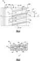
Figure 4 illustrates a plan view of the seal assembly ofFigure 3 . -
Figure 5 illustrates a sectional view of the seal assembly taken along line 4-4 ofFigure 3 . - Like reference numbers and designations in the various drawings indicate like elements.
-
Figure 1 schematically illustrates agas turbine engine 20. Thegas turbine engine 20 is disclosed herein as a two-spool turbofan that generally incorporates afan section 22, acompressor section 24, acombustor section 26 and aturbine section 28. Thefan section 22 drives air along a bypass flow path B in a bypass duct defined within anacelle 15, and also drives air along a core flow path C for compression and communication into thecombustor section 26 then expansion through theturbine section 28. Although depicted as a two-spool turbofan gas turbine engine in the disclosed non-limiting embodiment, it should be understood that the concepts described herein are not limited to use with two-spool turbofans as the teachings may be applied to other types of turbine engines including three-spool architectures. - The
exemplary engine 20 generally includes alow speed spool 30 and ahigh speed spool 32 mounted for rotation about an engine central longitudinal axis A relative to an enginestatic structure 36 viaseveral bearing systems 38. It should be understood thatvarious bearing systems 38 at various locations may alternatively or additionally be provided, and the location ofbearing systems 38 may be varied as appropriate to the application. - The
low speed spool 30 generally includes aninner shaft 40 that interconnects, a first (or low)pressure compressor 44 and a first (or low)pressure turbine 46. Theinner shaft 40 is connected to thefan 42 through a speed change mechanism, which in exemplarygas turbine engine 20 is illustrated as a gearedarchitecture 48 to drive afan 42 at a lower speed than thelow speed spool 30. Thehigh speed spool 32 includes anouter shaft 50 that interconnects a second (or high)pressure compressor 52 and a second (or high)pressure turbine 54. Acombustor 56 is arranged inexemplary gas turbine 20 between thehigh pressure compressor 52 and thehigh pressure turbine 54. Amid-turbine frame 57 of the enginestatic structure 36 may be arranged generally between thehigh pressure turbine 54 and thelow pressure turbine 46. Themid-turbine frame 57 further supports bearingsystems 38 in theturbine section 28. Theinner shaft 40 and theouter shaft 50 are concentric and rotate viabearing systems 38 about the engine central longitudinal axis A which is collinear with their longitudinal axes. - The core airflow is compressed by the
low pressure compressor 44 then thehigh pressure compressor 52, mixed and burned with fuel in thecombustor 56, then expanded over thehigh pressure turbine 54 andlow pressure turbine 46. Themid-turbine frame 57 includesairfoils 59 which are in the core airflow path C. Theturbines low speed spool 30 andhigh speed spool 32 in response to the expansion. It will be appreciated that each of the positions of thefan section 22,compressor section 24,combustor section 26,turbine section 28, and fandrive gear system 48 may be varied. For example,gear system 48 may be located aft of the low pressure compressor, or aft of thecombustor section 26 or even aft ofturbine section 28, andfan 42 may be positioned forward or aft of the location ofgear system 48. - The
engine 20 in one example is a high-bypass geared aircraft engine. In a further example, theengine 20 bypass ratio is greater than about six (6), with an example embodiment being greater than about ten (10), the gearedarchitecture 48 is an epicyclic gear train, such as a planetary gear system or other gear system, with a gear reduction ratio of greater than about 2.3 and thelow pressure turbine 46 has a pressure ratio that is greater than about five. In one disclosed embodiment, theengine 20 bypass ratio is greater than about ten (10:1), the fan diameter is significantly larger than that of thelow pressure compressor 44, and thelow pressure turbine 46 has a pressure ratio that is greater than about five 5:1.Low pressure turbine 46 pressure ratio is pressure measured prior to inlet oflow pressure turbine 46 as related to the pressure at the outlet of thelow pressure turbine 46 prior to an exhaust nozzle. The gearedarchitecture 48 may be an epicycle gear train, such as a planetary gear system or other gear system, with a gear reduction ratio of greater than about 2.3:1 and less than about 5:1. It should be understood, however, that the above parameters are only exemplary of one embodiment of a geared architecture engine and that the present invention is applicable to other gas turbine engines including direct drive turbofans. - A significant amount of thrust is provided by the bypass flow B due to the high bypass ratio. The
fan section 22 of theengine 20 is designed for a particular flight condition -- typically cruise at about 0.8 Mach and about 35,000 feet (10,668 meters). The flight condition of 0.8 Mach and 35,000 ft (10,668 meters), with the engine at its best fuel consumption - also known as "bucket cruise Thrust Specific Fuel Consumption ('TSFC')" - is the industry standard parameter of lbm of fuel being burned divided by lbf of thrust the engine produces at that minimum point. "Low fan pressure ratio" is the pressure ratio across the fan blade alone, without a Fan Exit Guide Vane ("FEGV") system. The low fan pressure ratio as disclosed herein according to one non-limiting embodiment is less than about 1.45. "Low corrected fan tip speed" is the actual fan tip speed in ft/sec divided by an industry standard temperature correction of [(Tram °R) / (518.7 °R)]0.5. The "Low corrected fan tip speed" as disclosed herein according to one non-limiting embodiment is less than about 1150 ft / second (350.5 meters/second). -
Figures 2-3 illustrate a bearingassembly 60 according to an example. The bearingassembly 60 can be incorporated into thecompressor section 24 orturbine section 28 of thegas turbine engine 20, such as one of the bearingsystems 38, for example. Other components of theengine 20 and other systems may benefit from the teachings herein, such as a towershaft coupled to one of theshafts - Referring to
Figure 2 , the bearingassembly 60 includes a bearinghousing 62 that is attached or otherwise secured to a portion of the enginestatic structure 36. The bearinghousing 62 extends along a longitudinal axis L to bound or otherwise define at least a portion of a bearing compartment BC. It should be appreciated that the bearing compartment BC can be defined by other portions of the enginestatic structure 36. The longitudinal axis L can be co-axial with or parallel to the engine longitudinal axis A ofFigure 1 . - The bearing
assembly 60 includes one or more bearings 64 (one shown for illustrative purposes) situated or received in the bearing compartment BC. Each bearing 64 can include one or more components such as a bearing carrier 65 including rotatable and static portions for supporting rotatable components of thebearing 64. In the illustrative example ofFigure 2 , bearing 64 is a ball bearing. Other example bearings include roller bearings and taper bearings. Thebearing 64 supports arotatable shaft 66. Theshaft 66 extends along and defines the longitudinal axis L. Theshaft 66 can include one or more portions mechanically attached to each other for rotation about the longitudinal axis L. Theturbine section 28 can drive at least one of thefan sections 22 andcompressor sections 24 through theshaft 66, for example. - The bearing compartment BC is an oil wetted environment that fluidly communicates with a lubricant source LS (shown in dashed lines) to deliver a lubricant LL such as oil to the bearing BC. The lubricant source LS can be an oil tank coupled to the
engine 20 or aircraft, for example. - A
wall 68 of the bearinghousing 62 bounds an airflow compartment or plenum P. In other examples,wall 68 is a separate and distinct component from the bearinghousing 62. The plenum P is fluidly coupled to a fluid source FS (shown in dashed lines for illustrative purposes). The fluid source FS is operable to convey pressurized flow F to the plenum P. Example fluid sources FS can include pressurized bleed air from thecompressor section 24 or another dedicated cooling supply, for example. - In some scenarios or operating regimes of the
engine 20, a relatively small difference in pressure may exist between the bearing compartment BC and plenum P. Buffer airflow at a relatively high pressure may otherwise need to be conveyed to the plenum P to maintain a sealing relationship across the perimeter of the bearing compartment BC. - The bearing
assembly 60 includes at least oneseal assembly 70 that bounds or otherwise defines a perimeter of the bearing compartment BC and a perimeter of the plenum P. Theseal assembly 70 establishes a fluid passage FP interconnecting the bearing compartment BC and plenum P. Theseal assembly 70 conveys pressurized airflow or fluid F to the perimeter of the bearing compartment BC to oppose migration of lubricant LL from the bearing compartment BC to the plenum P. Theseal member 78 includes one or more features that can establish a sealing relationship in a relatively low pressure differential environment and can reduce or otherwise eliminate the need for lubricant to establish the sealing relationship. - Referring to
Figure 3 , with continuing reference toFigure 2 , the bearinghousing 62 includes one or more seal lands 72 defined along aninner diameter 74 of the bearinghousing 62. In the illustrated example ofFigure 3 , the bearinghousing 62 includes three axially adjacent seal lands 72 (indicated at 72-1 to 72-3) that face inwardly towards the longitudinal axis L. Surfaces defining the seal lands 72 can be generally smooth or planar. - The
seal assembly 70 is arranged to fluidly separate the bearing compartment BC from the plenum P and to contain or otherwise oppose migration of lubricant LL from the bearing compartment BC to the plenum P, thereby reducing a likelihood of degradation of components of theengine 20 in relative high temperature locations such thecompressor section 24 orturbine section 28 ofFigure 1 . - The
seal assembly 70 including aseal carrier 76 and aseal member 78. Theseal carrier 76 is fixedly attached to anouter periphery 67 of theshaft 66. In other examples, theseal carrier 76 is mechanically attached or otherwise secured to the bearinghousing 62, to another portion of the enginestatic structure 36. Theseal member 78 is dimensioned to extend outwardly from theseal carrier 76. Theseal member 78 is a non-contacting type seal including aseal body 80 and aneck portion 82 that interconnects theseal carrier 76 and sealbody 80. Theseal body 80,neck portion 82, andseal carrier 76 are each swept about the longitudinal axis L to have a generally ring-shaped geometry. Theseal member 78 is dimensioned to extend outwardly in an axial direction from theneck portion 82 to form a shroud such that a cross section of theseal member 78 and neck portion together have a generally T-shaped geometry. Theseal body 80,neck portion 82, andseal carrier 76 can be integrally formed. In other examples, theseal body 80,neck portion 82, and/orseal carrier 76 are separate and distinct components that are mechanically attached to each other. - The
seal body 80 includes a plurality ofhelical teeth 84 interdigitated with a plurality ofhelical grooves 86. As illustrated byFigures 3 and5 , thehelical teeth 84 andhelical grooves 86 are placed in close proximity to theinner diameter 74 of the bearinghousing 62 to establish a sealing relationship with the first seal land 72-1. As illustrated byFigure 5 , each of thehelical teeth 84 has a generally rectangular cross sectional geometry, with a radially face defining anouter diameter 88 of theseal body 80. The generally rectangular cross sectional can reduce wear of surfaces of thehelical teeth 84 and/or first seal land 72-1 that may otherwise occur during contact. - The
helical teeth 84 andhelical grooves 86 are dimensioned to convey fluid F from the plenum P to a perimeter of the bearing compartment BC in response to rotation of theseal carrier 76 about the longitudinal axis L. During operation, thehelical teeth 84 produce an axial force component relative to the longitudinal axis L when interacting with fluid F such as airflow and/or lubricant. Thehelical teeth 84 can be arranged to serve as an axial air or fluid pump to augment the pressure differential between the fluid source FS and the bearing compartment BC, with fluid F conveyed through thehelical grooves 86. - Referring to
Figures 3-4 , theseal body 80 includes a firstvertical face 80A and a secondvertical face 80B axially spaced apart from the firstvertical face 80A. Thehelical teeth 84 andhelical grooves 86 extend at least partially between the first and secondvertical faces Figures 3-4 , each one of thehelical teeth 84 andhelical grooves 86 is dimensioned to extend in an axial direction with respect to the longitudinal axis L along theouter diameter 88 of theseal body 80 from the firstvertical face 80A to the secondvertical face 80B. - Referring to
Figure 4 , with continuing reference toFigure 3 , each of thehelical teeth 84 defines a respective tooth axis TA. Each of thegrooves 86 defines a respective groove axis GA. Each tooth axis TA and/or groove axis GA is skewed relative to the longitudinal axis L. Thehelical teeth 84 can be dimensioned with respect to diametral pitch (i.e., number of teeth per inch of pitch diameter), helix angle, and face width. - Each tooth axis TA defines a respective helix angle α with respect to the longitudinal axis L. In some examples, the helix angle α is equal to or greater than 5 degrees. In further examples, the helix angle α is less than or equal to 45 degrees, such as between 15 and 30 degrees. Each groove axis GA is defined such that each one of the
helical grooves 86 has a major component that extends in the axial direction relative to the longitudinal axis L. In examples, each of thehelical teeth 84 andhelical grooves 86 extends no more than a quarter rotation about the longitudinal axis L. Thehelical teeth 84 andhelical grooves 86 can have left or right handed orientations relative to the longitudinal axis L. - Referring back to
Figure 3 , theseal assembly 70 can include at least onesecondary seal 90, such as a labyrinth seal arrangement including at least oneknife edge seal 92. Although the onesecondary seal 90 ofFigure 3 includes knife edge seals 92, other seals can be utilized such as another non-contacting type seals and brush seals. Theseal member 78 is arranged to establish a primary (or first) sealing relationship that is sequential with a secondary (or second) sealing relationship established by thesecondary seal 90 adjacent the bearing compartment BC. Theseal member 78 establishes a sealing relationship along the fluid passage FP at a position between the bearing compartment BC and thesecondary seal 90. The knife edge seals 92 can serve to provide secondary sealing of the bearing compartment BC during low and/or no speed operations, for example. The knife edge seals 92 can also serve as a pressure limiter to oppose communication of flow F by theseal member 78 should communication of flow F exceed a predetermined threshold. - In the illustrated example of
Figure 3 , thesecondary seal 90 includes first and second knife edge seals 92-1, 92-2 that are spaced apart axially with respect to the longitudinal axis L. Each of the knife edge seals 92-1, 92-2 extends outwardly from theseal carrier 76 to establish a respective sealing relationship with the second and third seal lands 72-2, 72-3. The knife-edge seals 92 andseal member 78 can be integrally formed with theseal carrier 76. Although thesecondary seal 90 is disclosed having two knife edge seals 92-1, 92-2, it should be understood that thesecondary seal 90 can have fewer or more than two seals to reduce leakage across the fluid passage FP. - The bearing
assembly 60 can include one or more features that recapture lubricant LL that may escape or migrate away from the bearing assembly BC during engine operation. The bearinghousing 62 defines a drain passage (or drainback hole) 94 in a thickness of thewall 68 of the bearinghousing 62. Thedrain passage 94 extends along a passage axis PA between first andsecond ports drain passage 94 is dimensioned such that the passage axis PA is sloped towards theseal member 78 and/or longitudinal axis L. A projection of the passage axis PA can be oriented to intersect a surface of theseal member 78, such as the firstvertical face 80A of theseal member 78 and inlets of thehelical grooves 86 as illustrated byFigure 3 . - The
first port 96 is a drain port that is defined in the bearinghousing 62 along a surface of the bearing compartment BC that is opposed to theinner diameter 74 of the bearinghousing 62. Thesecond port 98 is defined along theinner diameter 74 of the bearinghousing 62 and along the fluid passage FP at a position axially between theseal member 78 andsecondary seal 90 to fluidly couple thedrain passage 94 and fluid passage FP. Thesecond port 98 andhelical teeth 84 can be radially aligned with respect to the longitudinal axis L, as illustrated byFigure 3 . First and/orsecond ports assembly 60 in the engine. - The
drain passage 94 allows any lubricant LL that collects in the bottom of the bearinghousing 62 to drain back into the bearing compartment BC. Thedrain passage 94 can also limit the localized low pressure zone adjacent theseal assembly 70 such that thedrain passage 94 limits or otherwise reduces a likelihood of aerodynamic flutter of the knife edge seals 92 and bearinghousing 62 during operation. - Operation of the
seal assembly 70 is as follows. Theseal member 78 is rotated relative to the bearinghousing 62 to establish a first sealing relationship along the fluid passage FP. Thehelical teeth 84 andhelical grooves 86 are dimensioned to establish the first sealing relationship in response to rotating theseal member 78. Theseal carrier 76 andseal member 78 are mounted to theshaft 66 such that rotating theshaft 66 about the longitudinal axis L establishes the first sealing relationship. Second and third sealing relationships can be established by the respective knife-edge seals 92-1, 92-2 in response to rotating theseal carrier 76. - Rotation of the
seal assembly 70 generates a pumping action to cause airflow or fluid F from the plenum P to move in an axial direction across theseal member 78 to the bearing compartment BC. Rotation ofseal assembly 70 including thehelical teeth 84 creates a localized positive pressure differential that augments the buffer source pressure of fluid F from the fluid source FS such that theseal assembly 70 can maintain a sealing relationship at relative low and/or negative differential pressures. Theseal member 78 opposes migration of lubricant LL along the fluid passage FP. The axial movement of the fluid F serves to carry any oil particles or lubricant LL back into the bearing compartment BC and creates an air or fluid barrier that minimizes or otherwise reduces a likelihood that lubricant LL escapes or migrates from the bearing compartment BC. Theseal assembly 70 is operable to communicate the lubricant LL from the fluid passage FP to thedrain passage 94, which is then drained or otherwise communicated from thedrain passage 94 back to the bearing compartment BC to recapture the lubricant LL. - The arrangements disclosed herein, including bearing and seal
assembly seal assembly 70 in low pressure differential environments which can reduce or avoid the need for an augmented air supply during starting and low speed motoring of theengine 20. A relatively lower pressure source can be utilized for buffer airflow to the bearing compartment BC, which can improve efficiency of the respective compressor providing the buffer airflow, for example. Theseal assembly 70 does not require lubricant to establish a sealing relationship due to a lack of a heat generating component, which can reduce demands on a thermal management system associated with theengine 20. The bearing and sealassembly engine 20, which can reduce emissions and a likelihood of auto-ignition of migrated lubricant. - It should be understood that relative positional terms such as "forward," "aft," "upper," "lower," "above," "below," and the like are with reference to the normal operational attitude of the vehicle and should not be considered otherwise limiting.
- Although the different examples have the specific components shown in the illustrations, embodiments of this disclosure are not limited to those particular combinations. It is possible to use some of the components or features from one of the examples in combination with features or components from another one of the examples. Although particular step sequences are shown, described, and claimed, it should be understood that steps may be performed in any order, separated or combined unless otherwise indicated and will still benefit from the present disclosure.
- The foregoing description is exemplary rather than defined by the limitations within. Various non-limiting embodiments are disclosed herein, however, one of ordinary skill in the art would recognize that various modifications and variations in light of the above teachings will fall within the scope of the appended claims. It is therefore to be understood that within the scope of the appended claims, the disclosure may be practiced other than as specifically described. For that reason the appended claims should be studied to determine true scope and content.
Claims (15)
- A seal assembly (70) for a gas turbine engine (20) comprising:a rotatable shaft (66) defining a longitudinal axis (L);a bearing housing (62) extending along the longitudinal axis (L) to define a bearing compartment (BC), the bearing housing (62) including a first seal land (72-1) defined along an inner diameter (74) of the bearing housing (62);a seal carrier (76) fixedly attached to an outer periphery (67) of the shaft (66);a seal member (78) extending outwardly from the seal carrier (76), the seal member (78) defining a plurality of helical grooves (86) facing radially outward to establish a first sealing relationship with the first seal land (72-1), each one of the helical grooves (86) has a major component extending in an axial direction relative to the longitudinal axis (L), and wherein each one of the helical grooves (86) defines a respective helix angle (α) relative to the longitudinal axis (L), and the helix angle (α) is between 5 degrees and 45 degrees;characterised in that a wall of the bearing housing (62) bounds a plenum (P), the plenum (P) being fluidly coupled to a fluid source (FS), and the helical grooves (86) are dimensioned to convey fluid from the plenum (P) to the bearing compartment (BC) in response to rotation of the seal carrier (76) about the engine longitudinal axis (L); andwherein the bearing housing (62) defines a drain passage (94) having a drain port (96) defined along the bearing compartment (BC) that allows lubricant (LL) that collects in the bottom of the bearing housing (62) to drain back into the bearing compartment (BC), and the drain passage (94) defines a passage axis (PA) having a projection that intersects the seal member (78).
- The seal assembly (70) as recited in claim 1, wherein the seal member (78) includes a seal body (80) including a plurality of helical teeth (84) that are interdigitated with the plurality of helical grooves (86), and each of the helical teeth (84) has a radial face defining an outer diameter of the seal body (80).
- The seal assembly (70) as recited in claim 2, wherein the seal member (78) includes a seal body (80) having a first vertical face (80A) and a second vertical face (80B) axially spaced apart from the first vertical face (80A), and each one of the helical grooves (86) extends in the axial direction along the outer diameter of the seal body (80) from the first vertical face (80A) to the second vertical face (80B).
- The seal assembly (70) as recited in claim 3, wherein the projection of the passage axis (PA) is oriented to intersect a vertical face of the seal member (78) and inlets of the helical grooves (86).
- The seal assembly (70) as recited in any of claims 1 to 4, further comprising at least one secondary seal (90) extending outwardly from the seal carrier (76) to establish a second sealing relationship with a second seal land defined along the inner diameter (74) of the bearing housing (62).
- The seal assembly (70) as recited in claim 5, wherein the seal member (78) establishes the first sealing relationship along a fluid passage (FP) at a position between the bearing compartment (BC) and the at least one secondary seal (90).
- The seal assembly (70) as recited in claim 6, wherein the seal member (78) and the at least secondary seal (90) are integrally formed with the seal carrier (76).
- The seal assembly (70) as recited in claim 6 or 7, wherein the drain passage (94) extends between a first port (96) and a second port (98), the first port is the drain port (96) the second port (98) is defined along the inner diameter (74) of the bearing housing (62) at a position axially between the at least one secondary seal (90) and the seal member (78) to fluidly couple the drain passage (94) and the fluid passage (FP).
- The seal assembly (70) as recited in claim 8, wherein the drain passage (94) defines a passage axis (PA) that is sloped towards the seal member (78).
- A gas turbine engine (20) comprising:a fan section including a plurality of fan blades;a compressor section;a turbine section driving at least one of the fan section and the compressor section through a rotatable shaft (66) that extends along an engine longitudinal axis (L); anda bearing assembly comprising:a bearing in the bearing compartment (BC) that supports the shaft (66); anda seal assembly (70) according to claim 1.
- The seal assembly (70) as recited in claim 1 or the gas turbine engine (20) as recited in claim 10, wherein:the seal member (78) includes a seal body (80) defining a plurality of helical teeth (84) that are interdigitated with the plurality of helical grooves (86), and each of the helical teeth (84) has a radial face defining an outer diameter of the seal body (80); andoptionally, wherein the seal assembly (70) includes first and second knife edge seals that extend outwardly from the seal carrier (76) to establish second and third sealing relationships with second and third seal lands defined by the bearing housing (62).
- The seal assembly (70) as recited in claim 1 or the gas turbine engine (20) as recited in any of claims 10 or 11, wherein the drain passage (94) extends between a first port (96) and a second port (98), the first port is the drain port, and the second port (98) is defined along an inner diameter (74) of the bearing housing (62), the inner diameter (74) defining the first seal land (72-1), and, optionally, wherein the gas turbine engine (20) further comprises:first and second knife edge seals extending outwardly from the seal carrier (76) to establish first and second sealing relationships with second and third seal lands defined along the inner diameter (74) of the bearing housing (62);wherein the seal member (78) establishes the first sealing relationship along a fluid passage (FP) at a position between the bearing compartment (BC) and the first and second knife edge seals, and the second port (98) is defined along the fluid passage (FP) between the seal member (78) and the first and second knife edge seals; andwherein the seal member (78) and the first and second knife edge seals are integrally formed with the seal carrier (76).
- A method of sealing for a gas turbine engine (20) comprising:rotating a seal member (78) relative to a bearing housing (62) to establish a first sealing relationship along a fluid passage (FP);wherein the bearing housing (62) extends along a longitudinal axis (L) to define a bearing compartment (BC), the fluid passage (FP) interconnecting the bearing compartment (BC) and a plenum (P), the plenum (P) fluidly coupled to a fluid source (FS) that conveys pressurized airflow;wherein the seal member (78) defines a plurality of helical teeth (84) that are interdigitated with a plurality of helical grooves (86) about an outer diameter of the seal member (78) to establish the first sealing relationship in response to the rotating, and each one of the helical grooves (86) has a major component extending in an axial direction relative to the longitudinal axis (L);wherein each one of the helical grooves (86) defines a respective helix angle (α) relative to the longitudinal axis (L), and the helix angle (α) is between 5 degrees and 45 degrees;characterised in that a wall of the bearing housing (62) bounds the plenum (P), and the helical grooves (86) are dimensioned to convey fluid from the plenum (P) to the bearing compartment (BC) in response to rotation of the seal carrier (76) about the engine longitudinal axis (L); andwherein the bearing housing (62) defines a drain passage (94) having a drain port (96) defined along the bearing compartment (BC) that allows lubricant (LL) that collects in the bottom of the bearing housing (62) to drain back into the bearing compartment (BC), and the drain passage (94) defines a passage axis (PA) having a projection that intersects the seal member (78).
- The method as recited in claim 13, wherein the bearing compartment (BC) includes a bearing that supports a rotatable shaft (66), the seal member (78) is mounted to the shaft (66), and the rotating step includes rotating the shaft (66) about the longitudinal axis (L) and, optionally, wherein the method further comprises communicating lubricant from the fluid passage (FP) to the drain passage (94), wherein the drain passage (94) extends between a first port (96) and a second port (98), the first port is the drain port, the second port (98) is defined along an inner diameter (74) of the bearing housing (62).
- The method as recited in claim 14, wherein the rotating step includes establishing a second sealing relationship between the bearing housing (62) and at least one knife edge seal, the seal member (78) and the at least one knife edge seal extending outwardly from a seal carrier (76), the seal carrier (76) fixedly attached to an outer periphery (67) of the shaft (66).
Applications Claiming Priority (1)
| Application Number | Priority Date | Filing Date | Title |
|---|---|---|---|
| US16/356,082 US11248492B2 (en) | 2019-03-18 | 2019-03-18 | Seal assembly for a gas turbine engine |
Publications (2)
| Publication Number | Publication Date |
|---|---|
| EP3712395A1 EP3712395A1 (en) | 2020-09-23 |
| EP3712395B1 true EP3712395B1 (en) | 2024-03-13 |
Family
ID=69845274
Family Applications (1)
| Application Number | Title | Priority Date | Filing Date |
|---|---|---|---|
| EP20163752.7A Active EP3712395B1 (en) | 2019-03-18 | 2020-03-17 | Seal assembly for a gas turbine engine |
Country Status (2)
| Country | Link |
|---|---|
| US (1) | US11248492B2 (en) |
| EP (1) | EP3712395B1 (en) |
Families Citing this family (1)
| Publication number | Priority date | Publication date | Assignee | Title |
|---|---|---|---|---|
| US11913466B2 (en) * | 2019-12-16 | 2024-02-27 | Ebara Corporation | Pump and rotary baffle plate |
Family Cites Families (55)
| Publication number | Priority date | Publication date | Assignee | Title |
|---|---|---|---|---|
| US3053590A (en) * | 1957-06-24 | 1962-09-11 | Shaft seal | |
| US4406459A (en) * | 1982-06-18 | 1983-09-27 | United Technologies Corporation | Oil weepage return for carbon seal plates |
| US4406460A (en) * | 1982-11-01 | 1983-09-27 | United Technologies Corporation | Anti-weepage valve for rotating seals |
| US4709545A (en) | 1983-05-31 | 1987-12-01 | United Technologies Corporation | Bearing compartment protection system |
| US4645415A (en) | 1983-12-23 | 1987-02-24 | United Technologies Corporation | Air cooler for providing buffer air to a bearing compartment |
| US5639095A (en) * | 1988-01-04 | 1997-06-17 | Twentieth Technology | Low-leakage and low-instability labyrinth seal |
| US4928978A (en) * | 1988-04-07 | 1990-05-29 | United Technologies Corporation | Rotating shaft seal |
| US5415478A (en) | 1994-05-17 | 1995-05-16 | Pratt & Whitney Canada, Inc. | Annular bearing compartment |
| US5658127A (en) * | 1996-01-26 | 1997-08-19 | Sundstrand Corporation | Seal element cooling in high speed mechanical face seals |
| US6131914A (en) * | 1996-08-30 | 2000-10-17 | United Technologies Corporation | Gas turbine engine bearing compartment seal |
| DE19916803A1 (en) | 1999-04-14 | 2000-10-19 | Rolls Royce Deutschland | Hydraulic sealing arrangement, in particular on a gas turbine |
| JP2002285802A (en) * | 2001-03-26 | 2002-10-03 | Toshiba Corp | Labyrinth sealing device for rotating machinery |
| US6470666B1 (en) | 2001-04-30 | 2002-10-29 | General Electric Company | Methods and systems for preventing gas turbine engine lube oil leakage |
| DE10148000A1 (en) | 2001-09-28 | 2003-04-10 | Rolls Royce Deutschland | oil separator |
| US6932350B1 (en) * | 2003-09-26 | 2005-08-23 | Ideal Electric Company | Windback labyrinth seal that accommodates a pressure differential for rotating shafts |
| US6996968B2 (en) | 2003-12-17 | 2006-02-14 | United Technologies Corporation | Bifurcated oil scavenge system for a gas turbine engine |
| US7093418B2 (en) | 2004-04-21 | 2006-08-22 | Honeywell International, Inc. | Gas turbine engine including a low pressure sump seal buffer source and thermally isolated sump |
| US7334982B2 (en) | 2005-05-06 | 2008-02-26 | General Electric Company | Apparatus for scavenging lubricating oil |
| US7878756B2 (en) * | 2007-10-31 | 2011-02-01 | United Technologies Corporation | Systems and methods for controlling seal clearance in a turbine engine |
| US7935164B2 (en) * | 2007-11-28 | 2011-05-03 | General Electric Company | Vortex air-oil separator system |
| US8905408B2 (en) * | 2008-05-22 | 2014-12-09 | Stein Seal Company | Windback device for a circumferential seal |
| US8092093B2 (en) | 2008-07-31 | 2012-01-10 | General Electric Company | Dynamic impeller oil seal |
| US9068571B2 (en) * | 2009-04-03 | 2015-06-30 | Ergoseal, Inc. | Seal for oil-free rotary displacement compressor |
| US8371127B2 (en) | 2009-10-01 | 2013-02-12 | Pratt & Whitney Canada Corp. | Cooling air system for mid turbine frame |
| FR2957976B1 (en) | 2010-03-26 | 2013-04-12 | Snecma | SEALING DEVICE FOR AN OIL ENCLOSURE OF A TURBOJET ENGINE |
| GB201109799D0 (en) | 2011-06-13 | 2011-07-27 | Rolls Royce Plc | A bearing chamber apparatus |
| KR101284925B1 (en) | 2011-11-21 | 2013-07-17 | 한국수자원공사 | Oil mist reduction device |
| GB201121232D0 (en) | 2011-12-12 | 2012-01-18 | Rolls Royce Plc | An air riding seal arrangement |
| US8366382B1 (en) | 2012-01-31 | 2013-02-05 | United Technologies Corporation | Mid-turbine frame buffer system |
| US9567908B2 (en) * | 2012-04-27 | 2017-02-14 | General Electric Company | Mitigating vortex pumping effect upstream of oil seal |
| US9353647B2 (en) * | 2012-04-27 | 2016-05-31 | General Electric Company | Wide discourager tooth |
| KR102027191B1 (en) * | 2012-09-18 | 2019-10-01 | 보르그워너 인코퍼레이티드 | Turbocharger shaft seal |
| US20140119887A1 (en) | 2012-11-01 | 2014-05-01 | United Technologies Corporation | Fluid-cooled seal arrangement for a gas turbine engine |
| FR2998922B1 (en) | 2012-12-05 | 2018-06-15 | Safran Aircraft Engines | SEALING OF TURBOMACHINE SPEAKERS REALIZED BY BRUSH JOINT AND LABYRINTH |
| US8919779B2 (en) | 2012-12-06 | 2014-12-30 | Rolls-Royce Plc | Air-riding seal |
| US9903224B2 (en) | 2012-12-29 | 2018-02-27 | United Technologies Corporation | Scupper channelling in gas turbine modules |
| US9683451B2 (en) * | 2013-01-04 | 2017-06-20 | United Technologies Corporation | Seal assembly for arranging between a stator and a rotor |
| US9506366B2 (en) * | 2013-08-06 | 2016-11-29 | General Electric Company | Helical seal system for a turbomachine |
| FR3016406B1 (en) | 2014-01-10 | 2016-02-12 | Snecma | TURBOMACHINE ASSEMBLY COMPRISING TWO BODIES AND MEANS FOR GUIDING A FLOWABLE FLUID FROM ONE BODY TO THE OTHER |
| US10731510B2 (en) * | 2014-05-16 | 2020-08-04 | Raython Technologies Group | Gas turbine engine with fluid damper |
| US9677423B2 (en) | 2014-06-20 | 2017-06-13 | Solar Turbines Incorporated | Compressor aft hub sealing system |
| CN105276192A (en) | 2014-10-16 | 2016-01-27 | 侯玉杰 | Manufacturing method for carbon-graphite floating ring |
| CA2911812A1 (en) | 2014-12-09 | 2016-06-09 | Phillip H. Burnside | Oil flow enhancer bearing assembly |
| US9803639B2 (en) * | 2014-12-19 | 2017-10-31 | Ghh-Rand Schraubenkompressoren Gmbh | Sectional sealing system for rotary screw compressor |
| FR3035154B1 (en) | 2015-04-17 | 2017-05-05 | Snecma | SEALING DEVICE FOR TURBOMACHINE BEARING OIL ENCLOSURE |
| DE102015117773A1 (en) | 2015-10-19 | 2017-04-20 | Rolls-Royce Deutschland Ltd & Co Kg | Jet engine with several chambers and a bearing chamber carrier |
| KR101730261B1 (en) * | 2015-10-23 | 2017-04-25 | 두산중공업 주식회사 | Assembly for turbine's sealing |
| US10648365B2 (en) * | 2015-12-08 | 2020-05-12 | General Electric Company | Gas turbine engine bearing sump and lubricant drain line from cooling passage |
| JP6677515B2 (en) * | 2016-01-14 | 2020-04-08 | 株式会社神戸製鋼所 | Oil-free screw compressor |
| US20180045316A1 (en) * | 2016-08-09 | 2018-02-15 | United Technologies Corporation | Hydrodynamic seal seat cooling features |
| EP3293360B1 (en) | 2016-09-13 | 2025-10-29 | RTX Corporation | Seal system with primary and secondary seal arrangement |
| US10584795B2 (en) * | 2017-03-29 | 2020-03-10 | Florida Turbine Technologies, Inc. | Interlocking axial labyrinth seal |
| US10161264B2 (en) | 2017-04-24 | 2018-12-25 | United Technologies Corporation | Helically actuated variable bearing damper |
| FR3067057B1 (en) | 2017-05-30 | 2020-01-10 | Safran Aircraft Engines | TURBOMACHINE COMPRISING AN OPTIMIZED LEAKAGE FLOW ENCLOSURE |
| US11028717B2 (en) | 2017-06-26 | 2021-06-08 | Raytheon Technologies Corporation | Bearing assembly for gas turbine engines |
-
2019
- 2019-03-18 US US16/356,082 patent/US11248492B2/en active Active
-
2020
- 2020-03-17 EP EP20163752.7A patent/EP3712395B1/en active Active
Also Published As
| Publication number | Publication date |
|---|---|
| US20200300117A1 (en) | 2020-09-24 |
| US11248492B2 (en) | 2022-02-15 |
| EP3712395A1 (en) | 2020-09-23 |
Similar Documents
| Publication | Publication Date | Title |
|---|---|---|
| EP2964928B1 (en) | Non-contacting seals for geared gas turbine engine bearing compartments | |
| EP3081753B1 (en) | Blade tip cooling arrangement | |
| US10458264B2 (en) | Seal arrangement for turbine engine component | |
| EP3623589B1 (en) | Bearing compartment oil auto-ignition mitigation | |
| EP3896264B1 (en) | Gas turbine engine with partial arc gutter | |
| EP3296519B1 (en) | Flowpath component for a gas turbine engine including a chordal seal | |
| US9482158B2 (en) | Turbomachine hybrid lift-off face seal | |
| EP3190266B1 (en) | Gas turbine engine comprising a rotor hub seal | |
| US11156098B2 (en) | Mate face arrangement for gas turbine engine components | |
| US12428970B2 (en) | Radial lift seal | |
| EP3712395B1 (en) | Seal assembly for a gas turbine engine | |
| US10443443B2 (en) | Non-contacting seals for geared gas turbine engine bearing compartments | |
| EP2955332B1 (en) | Geared turbofan engine with gearbox seal | |
| EP3047107B1 (en) | Gas turbine engine component platform seal cooling | |
| EP3643887B1 (en) | Gas turbine engine seal assemblies | |
| EP3372793B1 (en) | Non-contacting seals for geared gas turbine engine bearing compartments | |
| EP3822460B1 (en) | Gas turbine engine and cooling method |
Legal Events
| Date | Code | Title | Description |
|---|---|---|---|
| PUAI | Public reference made under article 153(3) epc to a published international application that has entered the european phase |
Free format text: ORIGINAL CODE: 0009012 |
|
| STAA | Information on the status of an ep patent application or granted ep patent |
Free format text: STATUS: THE APPLICATION HAS BEEN PUBLISHED |
|
| AK | Designated contracting states |
Kind code of ref document: A1 Designated state(s): AL AT BE BG CH CY CZ DE DK EE ES FI FR GB GR HR HU IE IS IT LI LT LU LV MC MK MT NL NO PL PT RO RS SE SI SK SM TR |
|
| AX | Request for extension of the european patent |
Extension state: BA ME |
|
| RAP1 | Party data changed (applicant data changed or rights of an application transferred) |
Owner name: RAYTHEON TECHNOLOGIES CORPORATION |
|
| STAA | Information on the status of an ep patent application or granted ep patent |
Free format text: STATUS: REQUEST FOR EXAMINATION WAS MADE |
|
| 17P | Request for examination filed |
Effective date: 20210323 |
|
| RBV | Designated contracting states (corrected) |
Designated state(s): AL AT BE BG CH CY CZ DE DK EE ES FI FR GB GR HR HU IE IS IT LI LT LU LV MC MK MT NL NO PL PT RO RS SE SI SK SM TR |
|
| STAA | Information on the status of an ep patent application or granted ep patent |
Free format text: STATUS: EXAMINATION IS IN PROGRESS |
|
| 17Q | First examination report despatched |
Effective date: 20211220 |
|
| GRAP | Despatch of communication of intention to grant a patent |
Free format text: ORIGINAL CODE: EPIDOSNIGR1 |
|
| STAA | Information on the status of an ep patent application or granted ep patent |
Free format text: STATUS: GRANT OF PATENT IS INTENDED |
|
| INTG | Intention to grant announced |
Effective date: 20231004 |
|
| RAP3 | Party data changed (applicant data changed or rights of an application transferred) |
Owner name: RTX CORPORATION |
|
| GRAS | Grant fee paid |
Free format text: ORIGINAL CODE: EPIDOSNIGR3 |
|
| GRAA | (expected) grant |
Free format text: ORIGINAL CODE: 0009210 |
|
| STAA | Information on the status of an ep patent application or granted ep patent |
Free format text: STATUS: THE PATENT HAS BEEN GRANTED |
|
| AK | Designated contracting states |
Kind code of ref document: B1 Designated state(s): AL AT BE BG CH CY CZ DE DK EE ES FI FR GB GR HR HU IE IS IT LI LT LU LV MC MK MT NL NO PL PT RO RS SE SI SK SM TR |
|
| REG | Reference to a national code |
Ref country code: GB Ref legal event code: FG4D |
|
| REG | Reference to a national code |
Ref country code: CH Ref legal event code: EP |
|
| REG | Reference to a national code |
Ref country code: DE Ref legal event code: R096 Ref document number: 602020027042 Country of ref document: DE |
|
| REG | Reference to a national code |
Ref country code: IE Ref legal event code: FG4D |
|
| PG25 | Lapsed in a contracting state [announced via postgrant information from national office to epo] |
Ref country code: LT Free format text: LAPSE BECAUSE OF FAILURE TO SUBMIT A TRANSLATION OF THE DESCRIPTION OR TO PAY THE FEE WITHIN THE PRESCRIBED TIME-LIMIT Effective date: 20240313 |
|
| REG | Reference to a national code |
Ref country code: LT Ref legal event code: MG9D |
|
| PG25 | Lapsed in a contracting state [announced via postgrant information from national office to epo] |
Ref country code: GR Free format text: LAPSE BECAUSE OF FAILURE TO SUBMIT A TRANSLATION OF THE DESCRIPTION OR TO PAY THE FEE WITHIN THE PRESCRIBED TIME-LIMIT Effective date: 20240614 |
|
| REG | Reference to a national code |
Ref country code: NL Ref legal event code: MP Effective date: 20240313 |
|
| PG25 | Lapsed in a contracting state [announced via postgrant information from national office to epo] |
Ref country code: HR Free format text: LAPSE BECAUSE OF FAILURE TO SUBMIT A TRANSLATION OF THE DESCRIPTION OR TO PAY THE FEE WITHIN THE PRESCRIBED TIME-LIMIT Effective date: 20240313 Ref country code: RS Free format text: LAPSE BECAUSE OF FAILURE TO SUBMIT A TRANSLATION OF THE DESCRIPTION OR TO PAY THE FEE WITHIN THE PRESCRIBED TIME-LIMIT Effective date: 20240613 |
|
| PG25 | Lapsed in a contracting state [announced via postgrant information from national office to epo] |
Ref country code: ES Free format text: LAPSE BECAUSE OF FAILURE TO SUBMIT A TRANSLATION OF THE DESCRIPTION OR TO PAY THE FEE WITHIN THE PRESCRIBED TIME-LIMIT Effective date: 20240313 |
|
| PG25 | Lapsed in a contracting state [announced via postgrant information from national office to epo] |
Ref country code: RS Free format text: LAPSE BECAUSE OF FAILURE TO SUBMIT A TRANSLATION OF THE DESCRIPTION OR TO PAY THE FEE WITHIN THE PRESCRIBED TIME-LIMIT Effective date: 20240613 Ref country code: NO Free format text: LAPSE BECAUSE OF FAILURE TO SUBMIT A TRANSLATION OF THE DESCRIPTION OR TO PAY THE FEE WITHIN THE PRESCRIBED TIME-LIMIT Effective date: 20240613 Ref country code: LT Free format text: LAPSE BECAUSE OF FAILURE TO SUBMIT A TRANSLATION OF THE DESCRIPTION OR TO PAY THE FEE WITHIN THE PRESCRIBED TIME-LIMIT Effective date: 20240313 Ref country code: HR Free format text: LAPSE BECAUSE OF FAILURE TO SUBMIT A TRANSLATION OF THE DESCRIPTION OR TO PAY THE FEE WITHIN THE PRESCRIBED TIME-LIMIT Effective date: 20240313 Ref country code: GR Free format text: LAPSE BECAUSE OF FAILURE TO SUBMIT A TRANSLATION OF THE DESCRIPTION OR TO PAY THE FEE WITHIN THE PRESCRIBED TIME-LIMIT Effective date: 20240614 Ref country code: FI Free format text: LAPSE BECAUSE OF FAILURE TO SUBMIT A TRANSLATION OF THE DESCRIPTION OR TO PAY THE FEE WITHIN THE PRESCRIBED TIME-LIMIT Effective date: 20240313 Ref country code: ES Free format text: LAPSE BECAUSE OF FAILURE TO SUBMIT A TRANSLATION OF THE DESCRIPTION OR TO PAY THE FEE WITHIN THE PRESCRIBED TIME-LIMIT Effective date: 20240313 Ref country code: BG Free format text: LAPSE BECAUSE OF FAILURE TO SUBMIT A TRANSLATION OF THE DESCRIPTION OR TO PAY THE FEE WITHIN THE PRESCRIBED TIME-LIMIT Effective date: 20240313 |
|
| REG | Reference to a national code |
Ref country code: AT Ref legal event code: MK05 Ref document number: 1665942 Country of ref document: AT Kind code of ref document: T Effective date: 20240313 |
|
| PG25 | Lapsed in a contracting state [announced via postgrant information from national office to epo] |
Ref country code: SE Free format text: LAPSE BECAUSE OF FAILURE TO SUBMIT A TRANSLATION OF THE DESCRIPTION OR TO PAY THE FEE WITHIN THE PRESCRIBED TIME-LIMIT Effective date: 20240313 Ref country code: LV Free format text: LAPSE BECAUSE OF FAILURE TO SUBMIT A TRANSLATION OF THE DESCRIPTION OR TO PAY THE FEE WITHIN THE PRESCRIBED TIME-LIMIT Effective date: 20240313 |
|
| PG25 | Lapsed in a contracting state [announced via postgrant information from national office to epo] |
Ref country code: NL Free format text: LAPSE BECAUSE OF FAILURE TO SUBMIT A TRANSLATION OF THE DESCRIPTION OR TO PAY THE FEE WITHIN THE PRESCRIBED TIME-LIMIT Effective date: 20240313 |
|
| PG25 | Lapsed in a contracting state [announced via postgrant information from national office to epo] |
Ref country code: NL Free format text: LAPSE BECAUSE OF FAILURE TO SUBMIT A TRANSLATION OF THE DESCRIPTION OR TO PAY THE FEE WITHIN THE PRESCRIBED TIME-LIMIT Effective date: 20240313 |
|
| PG25 | Lapsed in a contracting state [announced via postgrant information from national office to epo] |
Ref country code: IS Free format text: LAPSE BECAUSE OF FAILURE TO SUBMIT A TRANSLATION OF THE DESCRIPTION OR TO PAY THE FEE WITHIN THE PRESCRIBED TIME-LIMIT Effective date: 20240713 |
|
| PG25 | Lapsed in a contracting state [announced via postgrant information from national office to epo] |
Ref country code: SM Free format text: LAPSE BECAUSE OF FAILURE TO SUBMIT A TRANSLATION OF THE DESCRIPTION OR TO PAY THE FEE WITHIN THE PRESCRIBED TIME-LIMIT Effective date: 20240313 Ref country code: PT Free format text: LAPSE BECAUSE OF FAILURE TO SUBMIT A TRANSLATION OF THE DESCRIPTION OR TO PAY THE FEE WITHIN THE PRESCRIBED TIME-LIMIT Effective date: 20240715 |
|
| PG25 | Lapsed in a contracting state [announced via postgrant information from national office to epo] |
Ref country code: CZ Free format text: LAPSE BECAUSE OF FAILURE TO SUBMIT A TRANSLATION OF THE DESCRIPTION OR TO PAY THE FEE WITHIN THE PRESCRIBED TIME-LIMIT Effective date: 20240313 Ref country code: EE Free format text: LAPSE BECAUSE OF FAILURE TO SUBMIT A TRANSLATION OF THE DESCRIPTION OR TO PAY THE FEE WITHIN THE PRESCRIBED TIME-LIMIT Effective date: 20240313 |
|
| PG25 | Lapsed in a contracting state [announced via postgrant information from national office to epo] |
Ref country code: AT Free format text: LAPSE BECAUSE OF FAILURE TO SUBMIT A TRANSLATION OF THE DESCRIPTION OR TO PAY THE FEE WITHIN THE PRESCRIBED TIME-LIMIT Effective date: 20240313 |
|
| PG25 | Lapsed in a contracting state [announced via postgrant information from national office to epo] |
Ref country code: PL Free format text: LAPSE BECAUSE OF FAILURE TO SUBMIT A TRANSLATION OF THE DESCRIPTION OR TO PAY THE FEE WITHIN THE PRESCRIBED TIME-LIMIT Effective date: 20240313 |
|
| PG25 | Lapsed in a contracting state [announced via postgrant information from national office to epo] |
Ref country code: SK Free format text: LAPSE BECAUSE OF FAILURE TO SUBMIT A TRANSLATION OF THE DESCRIPTION OR TO PAY THE FEE WITHIN THE PRESCRIBED TIME-LIMIT Effective date: 20240313 |
|
| PG25 | Lapsed in a contracting state [announced via postgrant information from national office to epo] |
Ref country code: SM Free format text: LAPSE BECAUSE OF FAILURE TO SUBMIT A TRANSLATION OF THE DESCRIPTION OR TO PAY THE FEE WITHIN THE PRESCRIBED TIME-LIMIT Effective date: 20240313 Ref country code: SK Free format text: LAPSE BECAUSE OF FAILURE TO SUBMIT A TRANSLATION OF THE DESCRIPTION OR TO PAY THE FEE WITHIN THE PRESCRIBED TIME-LIMIT Effective date: 20240313 Ref country code: RO Free format text: LAPSE BECAUSE OF FAILURE TO SUBMIT A TRANSLATION OF THE DESCRIPTION OR TO PAY THE FEE WITHIN THE PRESCRIBED TIME-LIMIT Effective date: 20240313 Ref country code: PT Free format text: LAPSE BECAUSE OF FAILURE TO SUBMIT A TRANSLATION OF THE DESCRIPTION OR TO PAY THE FEE WITHIN THE PRESCRIBED TIME-LIMIT Effective date: 20240715 Ref country code: PL Free format text: LAPSE BECAUSE OF FAILURE TO SUBMIT A TRANSLATION OF THE DESCRIPTION OR TO PAY THE FEE WITHIN THE PRESCRIBED TIME-LIMIT Effective date: 20240313 Ref country code: IS Free format text: LAPSE BECAUSE OF FAILURE TO SUBMIT A TRANSLATION OF THE DESCRIPTION OR TO PAY THE FEE WITHIN THE PRESCRIBED TIME-LIMIT Effective date: 20240713 Ref country code: EE Free format text: LAPSE BECAUSE OF FAILURE TO SUBMIT A TRANSLATION OF THE DESCRIPTION OR TO PAY THE FEE WITHIN THE PRESCRIBED TIME-LIMIT Effective date: 20240313 Ref country code: CZ Free format text: LAPSE BECAUSE OF FAILURE TO SUBMIT A TRANSLATION OF THE DESCRIPTION OR TO PAY THE FEE WITHIN THE PRESCRIBED TIME-LIMIT Effective date: 20240313 Ref country code: AT Free format text: LAPSE BECAUSE OF FAILURE TO SUBMIT A TRANSLATION OF THE DESCRIPTION OR TO PAY THE FEE WITHIN THE PRESCRIBED TIME-LIMIT Effective date: 20240313 |
|
| REG | Reference to a national code |
Ref country code: CH Ref legal event code: PL |
|
| PG25 | Lapsed in a contracting state [announced via postgrant information from national office to epo] |
Ref country code: LU Free format text: LAPSE BECAUSE OF NON-PAYMENT OF DUE FEES Effective date: 20240317 |
|
| PG25 | Lapsed in a contracting state [announced via postgrant information from national office to epo] |
Ref country code: LU Free format text: LAPSE BECAUSE OF NON-PAYMENT OF DUE FEES Effective date: 20240317 |
|
| PG25 | Lapsed in a contracting state [announced via postgrant information from national office to epo] |
Ref country code: IT Free format text: LAPSE BECAUSE OF FAILURE TO SUBMIT A TRANSLATION OF THE DESCRIPTION OR TO PAY THE FEE WITHIN THE PRESCRIBED TIME-LIMIT Effective date: 20240313 |
|
| REG | Reference to a national code |
Ref country code: DE Ref legal event code: R097 Ref document number: 602020027042 Country of ref document: DE Ref country code: BE Ref legal event code: MM Effective date: 20240331 |
|
| PG25 | Lapsed in a contracting state [announced via postgrant information from national office to epo] |
Ref country code: IT Free format text: LAPSE BECAUSE OF FAILURE TO SUBMIT A TRANSLATION OF THE DESCRIPTION OR TO PAY THE FEE WITHIN THE PRESCRIBED TIME-LIMIT Effective date: 20240313 |
|
| PG25 | Lapsed in a contracting state [announced via postgrant information from national office to epo] |
Ref country code: MC Free format text: LAPSE BECAUSE OF FAILURE TO SUBMIT A TRANSLATION OF THE DESCRIPTION OR TO PAY THE FEE WITHIN THE PRESCRIBED TIME-LIMIT Effective date: 20240313 |
|
| PG25 | Lapsed in a contracting state [announced via postgrant information from national office to epo] |
Ref country code: DK Free format text: LAPSE BECAUSE OF FAILURE TO SUBMIT A TRANSLATION OF THE DESCRIPTION OR TO PAY THE FEE WITHIN THE PRESCRIBED TIME-LIMIT Effective date: 20240313 |
|
| PG25 | Lapsed in a contracting state [announced via postgrant information from national office to epo] |
Ref country code: BE Free format text: LAPSE BECAUSE OF NON-PAYMENT OF DUE FEES Effective date: 20240331 |
|
| PLBE | No opposition filed within time limit |
Free format text: ORIGINAL CODE: 0009261 |
|
| STAA | Information on the status of an ep patent application or granted ep patent |
Free format text: STATUS: NO OPPOSITION FILED WITHIN TIME LIMIT |
|
| PG25 | Lapsed in a contracting state [announced via postgrant information from national office to epo] |
Ref country code: IE Free format text: LAPSE BECAUSE OF NON-PAYMENT OF DUE FEES Effective date: 20240317 |
|
| PG25 | Lapsed in a contracting state [announced via postgrant information from national office to epo] |
Ref country code: MC Free format text: LAPSE BECAUSE OF FAILURE TO SUBMIT A TRANSLATION OF THE DESCRIPTION OR TO PAY THE FEE WITHIN THE PRESCRIBED TIME-LIMIT Effective date: 20240313 Ref country code: IE Free format text: LAPSE BECAUSE OF NON-PAYMENT OF DUE FEES Effective date: 20240317 Ref country code: DK Free format text: LAPSE BECAUSE OF FAILURE TO SUBMIT A TRANSLATION OF THE DESCRIPTION OR TO PAY THE FEE WITHIN THE PRESCRIBED TIME-LIMIT Effective date: 20240313 Ref country code: BE Free format text: LAPSE BECAUSE OF NON-PAYMENT OF DUE FEES Effective date: 20240331 Ref country code: CH Free format text: LAPSE BECAUSE OF NON-PAYMENT OF DUE FEES Effective date: 20240331 |
|
| 26N | No opposition filed |
Effective date: 20241216 |
|
| PG25 | Lapsed in a contracting state [announced via postgrant information from national office to epo] |
Ref country code: SI Free format text: LAPSE BECAUSE OF FAILURE TO SUBMIT A TRANSLATION OF THE DESCRIPTION OR TO PAY THE FEE WITHIN THE PRESCRIBED TIME-LIMIT Effective date: 20240313 |
|
| PG25 | Lapsed in a contracting state [announced via postgrant information from national office to epo] |
Ref country code: CY Free format text: LAPSE BECAUSE OF FAILURE TO SUBMIT A TRANSLATION OF THE DESCRIPTION OR TO PAY THE FEE WITHIN THE PRESCRIBED TIME-LIMIT; INVALID AB INITIO Effective date: 20200317 |
|
| PG25 | Lapsed in a contracting state [announced via postgrant information from national office to epo] |
Ref country code: HU Free format text: LAPSE BECAUSE OF FAILURE TO SUBMIT A TRANSLATION OF THE DESCRIPTION OR TO PAY THE FEE WITHIN THE PRESCRIBED TIME-LIMIT; INVALID AB INITIO Effective date: 20200317 |
|
| PG25 | Lapsed in a contracting state [announced via postgrant information from national office to epo] |
Ref country code: TR Free format text: LAPSE BECAUSE OF FAILURE TO SUBMIT A TRANSLATION OF THE DESCRIPTION OR TO PAY THE FEE WITHIN THE PRESCRIBED TIME-LIMIT Effective date: 20240313 |
|
| PGFP | Annual fee paid to national office [announced via postgrant information from national office to epo] |
Ref country code: GB Payment date: 20260219 Year of fee payment: 7 |
|
| PGFP | Annual fee paid to national office [announced via postgrant information from national office to epo] |
Ref country code: DE Payment date: 20260219 Year of fee payment: 7 |
|
| PGFP | Annual fee paid to national office [announced via postgrant information from national office to epo] |
Ref country code: FR Payment date: 20260219 Year of fee payment: 7 |