EP3712388A1 - Apparatus and method and system for inspecting a component of a gas turbine engine - Google Patents
Apparatus and method and system for inspecting a component of a gas turbine engine Download PDFInfo
- Publication number
- EP3712388A1 EP3712388A1 EP20164042.2A EP20164042A EP3712388A1 EP 3712388 A1 EP3712388 A1 EP 3712388A1 EP 20164042 A EP20164042 A EP 20164042A EP 3712388 A1 EP3712388 A1 EP 3712388A1
- Authority
- EP
- European Patent Office
- Prior art keywords
- pair
- sleeve
- orifices
- wall members
- opposing wall
- Prior art date
- Legal status (The legal status is an assumption and is not a legal conclusion. Google has not performed a legal analysis and makes no representation as to the accuracy of the status listed.)
- Granted
Links
Images

Classifications
-
- F—MECHANICAL ENGINEERING; LIGHTING; HEATING; WEAPONS; BLASTING
- F01—MACHINES OR ENGINES IN GENERAL; ENGINE PLANTS IN GENERAL; STEAM ENGINES
- F01D—NON-POSITIVE DISPLACEMENT MACHINES OR ENGINES, e.g. STEAM TURBINES
- F01D21/00—Shutting-down of machines or engines, e.g. in emergency; Regulating, controlling, or safety means not otherwise provided for
- F01D21/003—Arrangements for testing or measuring
-
- G—PHYSICS
- G01—MEASURING; TESTING
- G01N—INVESTIGATING OR ANALYSING MATERIALS BY DETERMINING THEIR CHEMICAL OR PHYSICAL PROPERTIES
- G01N27/00—Investigating or analysing materials by the use of electric, electrochemical, or magnetic means
- G01N27/72—Investigating or analysing materials by the use of electric, electrochemical, or magnetic means by investigating magnetic variables
-
- F—MECHANICAL ENGINEERING; LIGHTING; HEATING; WEAPONS; BLASTING
- F01—MACHINES OR ENGINES IN GENERAL; ENGINE PLANTS IN GENERAL; STEAM ENGINES
- F01D—NON-POSITIVE DISPLACEMENT MACHINES OR ENGINES, e.g. STEAM TURBINES
- F01D17/00—Regulating or controlling by varying flow
- F01D17/02—Arrangement of sensing elements
-
- G—PHYSICS
- G01—MEASURING; TESTING
- G01M—TESTING STATIC OR DYNAMIC BALANCE OF MACHINES OR STRUCTURES; TESTING OF STRUCTURES OR APPARATUS, NOT OTHERWISE PROVIDED FOR
- G01M15/00—Testing of engines
- G01M15/14—Testing gas-turbine engines or jet-propulsion engines
-
- G—PHYSICS
- G01—MEASURING; TESTING
- G01R—MEASURING ELECTRIC VARIABLES; MEASURING MAGNETIC VARIABLES
- G01R33/00—Arrangements or instruments for measuring magnetic variables
- G01R33/12—Measuring magnetic properties of articles or specimens of solids or fluids
- G01R33/1223—Measuring permeability, i.e. permeameters
-
- F—MECHANICAL ENGINEERING; LIGHTING; HEATING; WEAPONS; BLASTING
- F05—INDEXING SCHEMES RELATING TO ENGINES OR PUMPS IN VARIOUS SUBCLASSES OF CLASSES F01-F04
- F05D—INDEXING SCHEME FOR ASPECTS RELATING TO NON-POSITIVE-DISPLACEMENT MACHINES OR ENGINES, GAS-TURBINES OR JET-PROPULSION PLANTS
- F05D2260/00—Function
- F05D2260/80—Diagnostics
Definitions
- Embodiments of the present disclosure pertain to an apparatus and method for inspecting a component of a gas turbine engine and more specifically to an apparatus and method for inspecting an internal passage of a component a gas turbine engine.
- Engine run turbine hardware may return from the field and be overhauled. Accordingly, it is desirable to provide an apparatus and method for inspecting an internal passage of a component a gas turbine engine.
- a sleeve configured to surround a component of a gas turbine engine, the sleeve comprising: a pair of opposing wall members being secured to each other at at least one of a pair of opposite ends; an internal cavity located between the pair of opposing wall members, wherein the internal cavity extends from one end of the sleeve to an opposite end of the sleeve; and a plurality of orifices extending through the pair of opposing wall members.
- At least one of the plurality of orifices is located on one of the pair of opposing wall members and another one of the plurality of orifices is located on the other one of the pair of opposing wall members, wherein a center of the at least one of the plurality of orifices is axially aligned with a center of the another one of the plurality of orifices.
- the internal cavity has a configuration that surrounds an exterior surface of an airfoil, and wherein the airfoil is part of a turbine blade or vane.
- one of the pair of wall members is convex with respect to the internal cavity and the other one of the pair of wall members is concave with respect to the internal cavity.
- each of the plurality of orifices has a circular configuration.
- the sleeve is formed from a non-magnetic material.
- the sleeve is a sheet of material that is continuous at the at least one of the pairs of opposite ends.
- a system for inspecting one or more passages in a component of a gas turbine engine comprising: a sleeve configured to surround a component of a gas turbine engine, the sleeve comprising: a pair of opposing wall members being secured to each other at at least one of a pair of opposite ends; an internal cavity located between the pair of opposing wall members, wherein the internal cavity extends from one end of the sleeve to an opposite end of the sleeve; a plurality of orifices extending through the pair of opposing wall members; and a probe configured to be received within the plurality of orifices, wherein each of the plurality of orifices are configured to maintain the probe perpendicularly with respect to a surface of the component when the component is received in the sleeve and the probe is received in a first orifice of the plurality of orifices.
- At least one of the plurality of orifices is located on one of the pair of opposing wall members and another one of the plurality of orifices is located on the other one of the pair of opposing wall members, wherein a center of the at least one of the plurality of orifices is axially aligned with a center of the another one of the plurality of orifices.
- the internal cavity has a configuration that surrounds an exterior surface of an airfoil, and wherein the airfoil is part of a turbine blade or vane.
- one of the pair of opposing wall members is convex with respect to the internal cavity and the other one of the pair of opposing wall members is concave with respect to the internal cavity.
- each of the plurality of orifices has a circular configuration.
- the sleeve is formed from a non-magnetic material.
- the sleeve is a sheet of material that is continuous at the at least one of the pair of opposite ends.
- the probe is a magnetometer probe.
- a method for inspecting one or more passages of a component of a gas turbine engine comprising: positioning a sleeve about the component, the sleeve including: a pair of opposing wall members being secured to each other at at least one of a pair of opposite ends; an internal cavity located between the pair of opposing wall members, wherein the internal cavity extends from one end of the sleeve to an opposite end of the sleeve; and a plurality of orifices extending through the pair of opposing wall members; and inserting a probe into one of the plurality of orifices, wherein each of the plurality of orifices are configured to maintain the probe perpendicularly with respect to an outer surface of the component when the component is received in the sleeve and the probe is received in the first orifice.
- At least one of the plurality of orifices is located on one of the pair of opposing wall members and another one of the plurality of orifices is located on the other one of the pair of opposing wall members, wherein a center of the at least one of the plurality of orifices is axially aligned with a center of the another one of the plurality of orifices; and the method includes: inserting the probe into each orifice in one of the pair of opposing wall members to inspect magnetic permeability through the component.
- one of the pair of wall members is convex with respect to the internal cavity and the other one of the pair of wall members is concave with respect to the internal cavity; and the method includes: positioning the sleeve over the airfoil so each of the plurality of orifices in one of the pair of opposing wall members is located proximate a respective one of a plurality of passages in the airfoil.
- the method includes: inspecting magnetic permeability through the airfoil by: inserting the probe into the each of the plurality of orifices in one of the pair of opposing wall members; and then inserting the probe into each of the plurality of orifices in the other of the pair of opposing wall members.
- the method includes comparing measured magnetic permeability with a threshold value to determine a structural integrity of the component.
- FIG. 1 schematically illustrates a gas turbine engine 20.
- the gas turbine engine 20 is disclosed herein as a two-spool turbofan that generally incorporates a fan section 22, a compressor section 24, a combustor section 26 and a turbine section 28.
- Alternative engines might include other systems or features.
- the fan section 22 drives air along a bypass flow path B in a bypass duct, while the compressor section 24 drives air along a core flow path C for compression and communication into the combustor section 26 then expansion through the turbine section 28.
- FIG. 1 schematically illustrates a gas turbine engine 20.
- the gas turbine engine 20 is disclosed herein as a two-spool turbofan that generally incorporates a fan section 22, a compressor section 24, a combustor section 26 and a turbine section 28.
- Alternative engines might include other systems or features.
- the fan section 22 drives air along a bypass flow path B in a bypass duct
- the compressor section 24 drives air along a core flow path C for compression and communication into the combustor section 26
- the exemplary engine 20 generally includes a low speed spool 30 and a high speed spool 32 mounted for rotation about an engine central longitudinal axis A relative to an engine static structure 36 via several bearing systems 38. It should be understood that various bearing systems 38 at various locations may alternatively or additionally be provided, and the location of bearing systems 38 may be varied as appropriate to the application.
- the low speed spool 30 generally includes an inner shaft 40 that interconnects a fan 42, a low pressure compressor 44 and a low pressure turbine 46.
- the inner shaft 40 is connected to the fan 42 through a speed change mechanism, which in exemplary gas turbine engine 20 is illustrated as a geared architecture 48 to drive the fan 42 at a lower speed than the low speed spool 30.
- the high speed spool 32 includes an outer shaft 50 that interconnects a high pressure compressor 52 and high pressure turbine 54.
- a combustor 56 is arranged in exemplary gas turbine 20 between the high pressure compressor 52 and the high pressure turbine 54.
- An engine static structure 36 is arranged generally between the high pressure turbine 54 and the low pressure turbine 46.
- the engine static structure 36 further supports bearing systems 38 in the turbine section 28.
- the inner shaft 40 and the outer shaft 50 are concentric and rotate via bearing systems 38 about the engine central longitudinal axis A which is collinear with their longitudinal axes.
- each of the positions of the fan section 22, compressor section 24, combustor section 26, turbine section 28, and fan drive gear system 48 may be varied.
- gear system 48 may be located aft of combustor section 26 or even aft of turbine section 28, and fan section 22 may be positioned forward or aft of the location of gear system 48.
- the engine 20 in one example is a high-bypass geared aircraft engine.
- the engine 20 bypass ratio is greater than about six (6), with an example embodiment being greater than about ten (10)
- the geared architecture 48 is an epicyclic gear train, such as a planetary gear system or other gear system, with a gear reduction ratio of greater than about 2.3 and the low pressure turbine 46 has a pressure ratio that is greater than about five.
- the engine 20 bypass ratio is greater than about ten (10:1)
- the fan diameter is significantly larger than that of the low pressure compressor 44
- the low pressure turbine 46 has a pressure ratio that is greater than about five (5:1).
- Low pressure turbine 46 pressure ratio is pressure measured prior to inlet of low pressure turbine 46 as related to the pressure at the outlet of the low pressure turbine 46 prior to an exhaust nozzle.
- the geared architecture 48 may be an epicyclic gear train, such as a planetary gear system or other gear system, with a gear reduction ratio of greater than about 2.3:1. It should be understood, however, that the above parameters are only exemplary of one embodiment of a geared architecture engine and that the present disclosure is applicable to other gas turbine engines including direct drive turbofans.
- the fan section 22 of the engine 20 is designed for a particular flight condition--typically cruise at about 0.8Mach (274 m/s) and about 35,000 feet (10,668 meters).
- "Low fan pressure ratio” is the pressure ratio across the fan blade alone, without a Fan Exit Guide Vane (“FEGV”) system.
- the low fan pressure ratio as disclosed herein according to one non-limiting embodiment is less than about 1.45.
- Low corrected fan tip speed is the actual fan tip speed in ft/sec divided by an industry standard temperature correction of [(Tram °R)/(518.7 °R)]0.5.
- the "Low corrected fan tip speed” as disclosed herein according to one non-limiting embodiment is less than about 1150 ft/second (350.5 m/sec).
- a sleeve 100 for inspecting a plurality of internal passages 105 of a component 110 of a gas turbine engine 20 is illustrated.
- the sleeve 100 is configured to surround a component 110 of the gas turbine engine 20.
- the component 110 is an airfoil, such as part of a turbine blade or vane. Configuring the sleeve (100) to surround other components 110 of the gas turbine engine 20 is considered to be within the scope of the present disclosure.
- the sleeve 100 includes a pair of opposing wall members 120.
- the pair of opposing wall members 120 are secured to each at least one 130a of a pair of opposite ends (spaced along axis X in FIG. 2 ) 130.
- the sleeve 100 is a sheet of material that is continuous at the at least one 130a of the pair of opposite ends 130. In other words, the sleeve may be a single piece of material folded upon itself.
- An internal cavity 140 is located between the pair of opposing wall members 120. The internal cavity 140 extends from one end 150 of the sleeve 100 to an opposite end 160 (spaced from the one end 150 along axis Y in FIG. 2 ) of the sleeve 100.
- a plurality of orifices 170 extend through the pair of opposing wall members 120.
- At least one 170a of the plurality of orifices 170 is located on one 120a of the pair of opposing wall members 120. Another one 170b of the plurality of orifices 170 is located on the other one 120b of the pair of opposing wall members 120. A center 180a of the at least one 170a of the plurality of orifices 170 is axially aligned with a center 180b of the another one 170b of the plurality of orifices 170.
- the internal cavity 140 has a configuration that surrounds an exterior surface 110a of an airfoil 110 of a turbine blade or vane.
- the one 120a of the pair of wall members 120 is convex with respect to the internal cavity 140
- the other one 120b of the pair of wall members 120 is concave with respect to the internal cavity 140.
- the sleeve 100 also is configured so that each of the plurality of orifices 170 in the one 120a of the pair of opposing wall members 120 is located proximate a respective one of the plurality of passages 105 in the airfoil 110.
- the one 170a of the plurality of orifices 170 is opposite the another one 170b of the plurality of orifices 170 and axially aligned through one passage 105a of the plurality of passages, when the component 110 is received in the sleeve 100.
- a probe 185 is configured to be received within the plurality of orifices 170.
- Each of the plurality of orifices 170 are configured to maintain the probe 185 perpendicularly with respect to a surface 110a of the component 100 when the component 100 is received in the sleeve 100 and the probe 185 is received in anyone of the plurality of orifices 170.
- the probe 185 has a circular configuration and, accordingly, each of the plurality of orifices has a complementary circular configuration.
- other configurations for the probe and the matching orifice may be contemplated.
- the sleeve 100 is utilized for inspecting the plurality of passages 105 in the airfoil 110.
- the sleeve 100 is positioned about the airfoil 110 and then the probe 185, which may be a probe of a magnetometer 190, is inserted into one of the plurality of orifices 170.
- the probe 185 in one of the plurality of orifices 170, is aligned with another one of the plurality of orifices 170 and at least one passage of the plurality of passages 105.
- magnetometer 190 When magnetometer 190 is activated, magnetic permeability may be obtained through one or both of the wall members 120 surrounding one passage of the plurality of passages 105.
- the magnetic permeability may be compared with a threshold value to determine a structural integrity of the component 110.
- the sleeve 100 may be manufactured from a non-magnetic material to not interfere with the energy emitted from or read by the probe 185.
- the inspection process may include inserting the probe 185 into the each of the plurality of orifices 170 in the one 120a of the pair of opposing wall members 120. During this time, probe measurements may be taken at each of the plurality of orifices 170 in the one 120a of the pair of opposing wall members 120. Then the probe 185 may be inserted into each of the plurality of orifices 170 in the other 120b of the pair of opposing wall members 120. During this time, probe measurements may be taken at each of the plurality of orifices 170 in the other 120b of the pair of opposing wall members 120.
- permeability measurements may be obtained at each of the plurality of passages 105 from both of the pair of opposing wall members 120.
- the inspection process may be consistently repeated as desired to inspect for oxidation and corrosion in the airfoil 11.
Landscapes
- Physics & Mathematics (AREA)
- Engineering & Computer Science (AREA)
- General Physics & Mathematics (AREA)
- Chemical & Material Sciences (AREA)
- General Engineering & Computer Science (AREA)
- Mechanical Engineering (AREA)
- Analytical Chemistry (AREA)
- Life Sciences & Earth Sciences (AREA)
- Health & Medical Sciences (AREA)
- Biochemistry (AREA)
- General Health & Medical Sciences (AREA)
- Immunology (AREA)
- Pathology (AREA)
- Electrochemistry (AREA)
- Combustion & Propulsion (AREA)
- Chemical Kinetics & Catalysis (AREA)
- Condensed Matter Physics & Semiconductors (AREA)
- Turbine Rotor Nozzle Sealing (AREA)
- Investigating Or Analyzing Materials By The Use Of Magnetic Means (AREA)
Abstract
Description
- Embodiments of the present disclosure pertain to an apparatus and method for inspecting a component of a gas turbine engine and more specifically to an apparatus and method for inspecting an internal passage of a component a gas turbine engine.
- Engine run turbine hardware may return from the field and be overhauled. Accordingly, it is desirable to provide an apparatus and method for inspecting an internal passage of a component a gas turbine engine.
- Disclosed is a sleeve configured to surround a component of a gas turbine engine, the sleeve comprising: a pair of opposing wall members being secured to each other at at least one of a pair of opposite ends; an internal cavity located between the pair of opposing wall members, wherein the internal cavity extends from one end of the sleeve to an opposite end of the sleeve; and a plurality of orifices extending through the pair of opposing wall members.
- In addition to one or more of the above disclosed features or as an alternate, at least one of the plurality of orifices is located on one of the pair of opposing wall members and another one of the plurality of orifices is located on the other one of the pair of opposing wall members, wherein a center of the at least one of the plurality of orifices is axially aligned with a center of the another one of the plurality of orifices.
- In addition to one or more of the above disclosed features or as an alternate, the internal cavity has a configuration that surrounds an exterior surface of an airfoil, and wherein the airfoil is part of a turbine blade or vane.
- In addition to one or more of the above disclosed features or as an alternate, one of the pair of wall members is convex with respect to the internal cavity and the other one of the pair of wall members is concave with respect to the internal cavity.
- In addition to one or more of the above disclosed features or as an alternate, each of the plurality of orifices has a circular configuration.
- In addition to one or more of the above disclosed features or as an alternate, the sleeve is formed from a non-magnetic material.
- In addition to one or more of the above disclosed features or as an alternate, the sleeve is a sheet of material that is continuous at the at least one of the pairs of opposite ends.
- Disclosed is a system for inspecting one or more passages in a component of a gas turbine engine, the system comprising: a sleeve configured to surround a component of a gas turbine engine, the sleeve comprising: a pair of opposing wall members being secured to each other at at least one of a pair of opposite ends; an internal cavity located between the pair of opposing wall members, wherein the internal cavity extends from one end of the sleeve to an opposite end of the sleeve; a plurality of orifices extending through the pair of opposing wall members; and a probe configured to be received within the plurality of orifices, wherein each of the plurality of orifices are configured to maintain the probe perpendicularly with respect to a surface of the component when the component is received in the sleeve and the probe is received in a first orifice of the plurality of orifices.
- In addition to one or more of the above disclosed features or as an alternate, at least one of the plurality of orifices is located on one of the pair of opposing wall members and another one of the plurality of orifices is located on the other one of the pair of opposing wall members, wherein a center of the at least one of the plurality of orifices is axially aligned with a center of the another one of the plurality of orifices.
- In addition to one or more of the above disclosed features or as an alternate, the internal cavity has a configuration that surrounds an exterior surface of an airfoil, and wherein the airfoil is part of a turbine blade or vane.
- In addition to one or more of the above disclosed features or as an alternate, one of the pair of opposing wall members is convex with respect to the internal cavity and the other one of the pair of opposing wall members is concave with respect to the internal cavity.
- In addition to one or more of the above disclosed features or as an alternate, each of the plurality of orifices has a circular configuration.
- In addition to one or more of the above disclosed features or as an alternate, the sleeve is formed from a non-magnetic material.
- In addition to one or more of the above disclosed features or as an alternate, the sleeve is a sheet of material that is continuous at the at least one of the pair of opposite ends.
- In addition to one or more of the above disclosed features or as an alternate, the probe is a magnetometer probe.
- Disclosed is a method for inspecting one or more passages of a component of a gas turbine engine, the method comprising: positioning a sleeve about the component, the sleeve including: a pair of opposing wall members being secured to each other at at least one of a pair of opposite ends; an internal cavity located between the pair of opposing wall members, wherein the internal cavity extends from one end of the sleeve to an opposite end of the sleeve; and a plurality of orifices extending through the pair of opposing wall members; and inserting a probe into one of the plurality of orifices, wherein each of the plurality of orifices are configured to maintain the probe perpendicularly with respect to an outer surface of the component when the component is received in the sleeve and the probe is received in the first orifice.
- In addition to one or more of the above disclosed features or as an alternate, at least one of the plurality of orifices is located on one of the pair of opposing wall members and another one of the plurality of orifices is located on the other one of the pair of opposing wall members, wherein a center of the at least one of the plurality of orifices is axially aligned with a center of the another one of the plurality of orifices; and the method includes: inserting the probe into each orifice in one of the pair of opposing wall members to inspect magnetic permeability through the component.
- In addition to one or more of the above disclosed features or as an alternate, one of the pair of wall members is convex with respect to the internal cavity and the other one of the pair of wall members is concave with respect to the internal cavity; and the method includes: positioning the sleeve over the airfoil so each of the plurality of orifices in one of the pair of opposing wall members is located proximate a respective one of a plurality of passages in the airfoil.
- In addition to one or more of the above disclosed features or as an alternate, the method includes: inspecting magnetic permeability through the airfoil by: inserting the probe into the each of the plurality of orifices in one of the pair of opposing wall members; and then inserting the probe into each of the plurality of orifices in the other of the pair of opposing wall members.
- In addition to one or more of the above disclosed features or as an alternate, the method includes comparing measured magnetic permeability with a threshold value to determine a structural integrity of the component.
- The following descriptions should not be considered limiting in any way. With reference to the accompanying drawings, like elements are numbered alike:
-
FIG. 1 is a partial cross-sectional view of a gas turbine engine; -
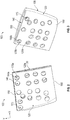
FIGS. 2 and 3 are perspective views of a sleeve in accordance with the present disclosure; and -
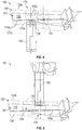
FIGS. 4 and 5 illustrate the sleeve ofFIGS. 2 and 3 disposed on an airfoil. - A detailed description of one or more embodiments of the disclosed apparatus and method are presented herein by way of exemplification and not limitation with reference to the FIGS.
-
FIG. 1 schematically illustrates agas turbine engine 20. Thegas turbine engine 20 is disclosed herein as a two-spool turbofan that generally incorporates afan section 22, acompressor section 24, acombustor section 26 and aturbine section 28. Alternative engines might include other systems or features. Thefan section 22 drives air along a bypass flow path B in a bypass duct, while thecompressor section 24 drives air along a core flow path C for compression and communication into thecombustor section 26 then expansion through theturbine section 28. Although depicted as a two-spool turbofan gas turbine engine in the disclosed non-limiting embodiment, it should be understood that the concepts described herein are not limited to use with two-spool turbofans as the teachings may be applied to other types of turbine engines including three-spool architectures. - The
exemplary engine 20 generally includes alow speed spool 30 and ahigh speed spool 32 mounted for rotation about an engine central longitudinal axis A relative to an enginestatic structure 36 viaseveral bearing systems 38. It should be understood thatvarious bearing systems 38 at various locations may alternatively or additionally be provided, and the location ofbearing systems 38 may be varied as appropriate to the application. - The
low speed spool 30 generally includes aninner shaft 40 that interconnects afan 42, alow pressure compressor 44 and alow pressure turbine 46. Theinner shaft 40 is connected to thefan 42 through a speed change mechanism, which in exemplarygas turbine engine 20 is illustrated as a gearedarchitecture 48 to drive thefan 42 at a lower speed than thelow speed spool 30. Thehigh speed spool 32 includes anouter shaft 50 that interconnects ahigh pressure compressor 52 andhigh pressure turbine 54. Acombustor 56 is arranged inexemplary gas turbine 20 between thehigh pressure compressor 52 and thehigh pressure turbine 54. An enginestatic structure 36 is arranged generally between thehigh pressure turbine 54 and thelow pressure turbine 46. The enginestatic structure 36 further supports bearingsystems 38 in theturbine section 28. Theinner shaft 40 and theouter shaft 50 are concentric and rotate viabearing systems 38 about the engine central longitudinal axis A which is collinear with their longitudinal axes. - The core airflow is compressed by the
low pressure compressor 44 then thehigh pressure compressor 52, mixed and burned with fuel in thecombustor 56, then expanded over thehigh pressure turbine 54 andlow pressure turbine 46. Theturbines low speed spool 30 andhigh speed spool 32 in response to the expansion. It will be appreciated that each of the positions of thefan section 22,compressor section 24,combustor section 26,turbine section 28, and fandrive gear system 48 may be varied. For example,gear system 48 may be located aft ofcombustor section 26 or even aft ofturbine section 28, andfan section 22 may be positioned forward or aft of the location ofgear system 48. - The
engine 20 in one example is a high-bypass geared aircraft engine. In a further example, theengine 20 bypass ratio is greater than about six (6), with an example embodiment being greater than about ten (10), the gearedarchitecture 48 is an epicyclic gear train, such as a planetary gear system or other gear system, with a gear reduction ratio of greater than about 2.3 and thelow pressure turbine 46 has a pressure ratio that is greater than about five. In one disclosed embodiment, theengine 20 bypass ratio is greater than about ten (10:1), the fan diameter is significantly larger than that of thelow pressure compressor 44, and thelow pressure turbine 46 has a pressure ratio that is greater than about five (5:1).Low pressure turbine 46 pressure ratio is pressure measured prior to inlet oflow pressure turbine 46 as related to the pressure at the outlet of thelow pressure turbine 46 prior to an exhaust nozzle. The gearedarchitecture 48 may be an epicyclic gear train, such as a planetary gear system or other gear system, with a gear reduction ratio of greater than about 2.3:1. It should be understood, however, that the above parameters are only exemplary of one embodiment of a geared architecture engine and that the present disclosure is applicable to other gas turbine engines including direct drive turbofans. - A significant amount of thrust is provided by the bypass flow B due to the high bypass ratio. The
fan section 22 of theengine 20 is designed for a particular flight condition--typically cruise at about 0.8Mach (274 m/s) and about 35,000 feet (10,668 meters). The flight condition of 0.8 Mach (274 m/s) and 35,000 ft. (10,668 meters), with the engine at its best fuel consumption--also known as "bucket cruise Thrust Specific Fuel Consumption ('TSFC')"--is the industry standard parameter of lbm of fuel being burned divided by lbf of thrust the engine produces at that minimum point. "Low fan pressure ratio" is the pressure ratio across the fan blade alone, without a Fan Exit Guide Vane ("FEGV") system. The low fan pressure ratio as disclosed herein according to one non-limiting embodiment is less than about 1.45. "Low corrected fan tip speed" is the actual fan tip speed in ft/sec divided by an industry standard temperature correction of [(Tram °R)/(518.7 °R)]0.5. The "Low corrected fan tip speed" as disclosed herein according to one non-limiting embodiment is less than about 1150 ft/second (350.5 m/sec). - Turning to
FIGS. 2 - 5 , asleeve 100 for inspecting a plurality ofinternal passages 105 of acomponent 110 of agas turbine engine 20 is illustrated. Thesleeve 100 is configured to surround acomponent 110 of thegas turbine engine 20. In one embodiment thecomponent 110 is an airfoil, such as part of a turbine blade or vane. Configuring the sleeve (100) to surroundother components 110 of thegas turbine engine 20 is considered to be within the scope of the present disclosure. - The
sleeve 100 includes a pair of opposingwall members 120. The pair of opposingwall members 120 are secured to each at least one 130a of a pair of opposite ends (spaced along axis X inFIG. 2 ) 130. In one embodiment, thesleeve 100 is a sheet of material that is continuous at the at least one 130a of the pair of opposite ends 130. In other words, the sleeve may be a single piece of material folded upon itself. Aninternal cavity 140 is located between the pair of opposingwall members 120. Theinternal cavity 140 extends from oneend 150 of thesleeve 100 to an opposite end 160 (spaced from the oneend 150 along axis Y inFIG. 2 ) of thesleeve 100. A plurality oforifices 170 extend through the pair of opposingwall members 120. - At least one 170a of the plurality of
orifices 170 is located on one 120a of the pair of opposingwall members 120. Another one 170b of the plurality oforifices 170 is located on the other one 120b of the pair of opposingwall members 120. Acenter 180a of the at least one 170a of the plurality oforifices 170 is axially aligned with acenter 180b of the another one 170b of the plurality oforifices 170. - Turning to
FIGS. 4 and 5 and, in one embodiment, theinternal cavity 140 has a configuration that surrounds anexterior surface 110a of anairfoil 110 of a turbine blade or vane. In such embodiment, the one 120a of the pair ofwall members 120 is convex with respect to theinternal cavity 140, and the other one 120b of the pair ofwall members 120 is concave with respect to theinternal cavity 140. Thesleeve 100 also is configured so that each of the plurality oforifices 170 in the one 120a of the pair of opposingwall members 120 is located proximate a respective one of the plurality ofpassages 105 in theairfoil 110. With this configuration, the one 170a of the plurality oforifices 170 is opposite the another one 170b of the plurality oforifices 170 and axially aligned through one passage 105a of the plurality of passages, when thecomponent 110 is received in thesleeve 100. - A
probe 185 is configured to be received within the plurality oforifices 170. Each of the plurality oforifices 170 are configured to maintain theprobe 185 perpendicularly with respect to asurface 110a of thecomponent 100 when thecomponent 100 is received in thesleeve 100 and theprobe 185 is received in anyone of the plurality oforifices 170. As illustrated and in one non-limiting embodiment, theprobe 185 has a circular configuration and, accordingly, each of the plurality of orifices has a complementary circular configuration. Of course, other configurations for the probe and the matching orifice may be contemplated. - The
sleeve 100 is utilized for inspecting the plurality ofpassages 105 in theairfoil 110. For example, thesleeve 100 is positioned about theairfoil 110 and then theprobe 185, which may be a probe of amagnetometer 190, is inserted into one of the plurality oforifices 170. Theprobe 185, in one of the plurality oforifices 170, is aligned with another one of the plurality oforifices 170 and at least one passage of the plurality ofpassages 105. Whenmagnetometer 190 is activated, magnetic permeability may be obtained through one or both of thewall members 120 surrounding one passage of the plurality ofpassages 105. The magnetic permeability may be compared with a threshold value to determine a structural integrity of thecomponent 110. Thesleeve 100 may be manufactured from a non-magnetic material to not interfere with the energy emitted from or read by theprobe 185. - Due to the configuration of the plurality of
orifices 170 in thesleeve 100, the inspection process may include inserting theprobe 185 into the each of the plurality oforifices 170 in the one 120a of the pair of opposingwall members 120. During this time, probe measurements may be taken at each of the plurality oforifices 170 in the one 120a of the pair of opposingwall members 120. Then theprobe 185 may be inserted into each of the plurality oforifices 170 in the other 120b of the pair of opposingwall members 120. During this time, probe measurements may be taken at each of the plurality oforifices 170 in the other 120b of the pair of opposingwall members 120. Thus, permeability measurements may be obtained at each of the plurality ofpassages 105 from both of the pair of opposingwall members 120. With the controlled orientation of theprobe 185 within each of the plurality oforifices 170, the inspection process may be consistently repeated as desired to inspect for oxidation and corrosion in the airfoil 11. - The terminology used herein is for the purpose of describing particular embodiments only and is not intended to be limiting of the present disclosure. As used herein, the singular forms "a", "an" and "the" are intended to include the plural forms as well, unless the context clearly indicates otherwise. It will be further understood that the terms "comprises" and/or "comprising," when used in this specification, specify the presence of stated features, integers, steps, operations, elements, and/or components, but do not preclude the presence or addition of one or more other features, integers, steps, operations, element components, and/or groups thereof.
- While the present disclosure has been described with reference to an exemplary embodiment or embodiments, it will be understood by those skilled in the art that various changes may be made and equivalents may be substituted for elements thereof without departing from the scope of the present disclosure. In addition, many modifications may be made to adapt a particular situation or material to the teachings of the present disclosure without departing from the essential scope thereof. Therefore, it is intended that the present disclosure not be limited to the particular embodiment disclosed as the best mode contemplated for carrying out this present disclosure, but that the present disclosure will include all embodiments falling within the scope of the claims.
Claims (14)
- A sleeve (100) configured to surround a component (110) of a gas turbine engine (20), the sleeve (100) comprising:a pair of opposing wall members (120) being secured to each other at at least one of a pair of opposite ends (130);an internal cavity (140) located between the pair of opposing wall members (120), wherein the internal cavity (140) extends from one end (150) of the sleeve (100) to an opposite end (160) of the sleeve (100); anda plurality of orifices (170) extending through the pair of opposing wall members (120).
- The sleeve (100) of claim 1, wherein at least one (170a) of the plurality of orifices (170) is located on one (120a) of the pair of opposing wall members (120) and another one (170b) of the plurality of orifices (170) is located on the other one (120b) of the pair of opposing wall members (120), wherein a center (180a) of the at least one (170a) of the plurality of orifices (170) is axially aligned with a center (180b) of the another one (170b) of the plurality of orifices (170).
- The sleeve (100) of claim 1 or 2, wherein the internal cavity (140) has a configuration that surrounds an exterior surface (110a) of an airfoil (110), and wherein the airfoil (110) is part of a turbine blade or vane.
- The sleeve (100) of claim 1, 2 or 3, wherein one (120a) of the pair of wall members (120) is convex with respect to the internal cavity (140) and the other one (120b) of the pair of wall members (120) is concave with respect to the internal cavity (140).
- The sleeve (100) of any preceding claim, wherein each of the plurality of orifices (170) has a circular configuration.
- The sleeve (100) of any preceding claim, wherein the sleeve (100) is formed from a non-magnetic material.
- The sleeve (100) of any preceding claim, wherein the sleeve (100) is a sheet of material that is continuous at the at least one of the pairs of opposite ends (130).
- A system for inspecting one or more passages (105) in a component (110) of a gas turbine engine (20), the system comprising:a sleeve (100) as claimed in any of claims 1 to 7; anda probe (185) configured to be received within the plurality of orifices (170) of the sleeve (100), wherein each of the plurality of orifices (170) are configured to maintain the probe (185) perpendicularly with respect to a surface (110a) of the component (110) when the component is received in the sleeve (100) and the probe (185) is received in a first orifice of the plurality of orifices (170).
- The system of claim 8, wherein the probe (185) is a magnetometer probe (190).
- A method for inspecting one or more passages (105) of a component (110) of a gas turbine engine (20), the method comprising:positioning a sleeve (100) about the component (110), the sleeve (100) including: a pair of opposing wall members (130) being secured to each other at at least one of a pair of opposite ends (130); an internal cavity (140) located between the pair of opposing wall members (120), wherein the internal cavity (140) extends from one end (150) of the sleeve (100) to an opposite end (160) of the sleeve (100); and a plurality of orifices (170) extending through the pair of opposing wall members (120); andinserting a probe (185) into one (170a) of the plurality of orifices (170), wherein each of the plurality of orifices (170) are configured to maintain the probe (185) perpendicularly with respect to an outer surface (110a) of the component (100) when the component (110) is received in the sleeve (100) and the probe (185) is received in the first orifice (170a).
- The method of claim 10, wherein at least one (170a) of the plurality of orifices (170) is located on one (120c) of the pair of opposing wall members (120) and another one (170b) of the plurality of orifices (170) is located on the other one of the pair of opposing wall members (120), wherein a center (180a) of the at least one (170c) of the plurality of orifices (170) is axially aligned with a center (180b) of the another one (170b) of the plurality of orifices (170); and
the method includes:
inserting the probe (185) into each orifice (170) in one of the pair of opposing wall members (120) to inspect magnetic permeability through the component (110). - The method of claim 10 or 11, wherein the component (110) is an airfoil, and one (120a) of the pair of wall members (120) is convex with respect to the internal cavity (140) and the other one (120b) of the pair of wall members (120) is concave with respect to the internal cavity (140); and
the method includes:
positioning the sleeve (100) over the airfoil (110) so each of the plurality of orifices (170) in one of the pair of opposing wall members (120) is located proximate a respective one of a plurality of passages (105) in the airfoil (110). - The method of claim 12, comprising:
inspecting magnetic permeability through the airfoil (110) by:inserting the probe (185) into the each of the plurality of orifices (170) in one (120a) of the pair of opposing wall members (120); andthen inserting the probe (185) into each of the plurality of orifices (190) in the other (120b) of the pair of opposing wall members (120). - The method of claim 13, comprising comparing measured magnetic permeability with a threshold value to determine a structural integrity of the component (110).
Applications Claiming Priority (1)
| Application Number | Priority Date | Filing Date | Title |
|---|---|---|---|
| US16/359,550 US10816507B2 (en) | 2019-03-20 | 2019-03-20 | Apparatus and method and system for inspecting a component of a gas turbine engine |
Publications (2)
| Publication Number | Publication Date |
|---|---|
| EP3712388A1 true EP3712388A1 (en) | 2020-09-23 |
| EP3712388B1 EP3712388B1 (en) | 2023-04-26 |
Family
ID=69846012
Family Applications (1)
| Application Number | Title | Priority Date | Filing Date |
|---|---|---|---|
| EP20164042.2A Active EP3712388B1 (en) | 2019-03-20 | 2020-03-18 | Apparatus and method and system for inspecting a component of a gas turbine engine |
Country Status (2)
| Country | Link |
|---|---|
| US (1) | US10816507B2 (en) |
| EP (1) | EP3712388B1 (en) |
Families Citing this family (3)
| Publication number | Priority date | Publication date | Assignee | Title |
|---|---|---|---|---|
| US11428122B1 (en) * | 2021-03-23 | 2022-08-30 | Pratt & Whitney Canada Corp. | Thermal protection for a gas turbine engine probe |
| US11339679B1 (en) * | 2021-03-23 | 2022-05-24 | Pratt & Whitney Canada Corp. | Turbine probe heat shielding |
| US11859503B1 (en) | 2022-06-30 | 2024-01-02 | Pratt & Whitney Canada Corp. | Probe heat shielding |
Citations (5)
| Publication number | Priority date | Publication date | Assignee | Title |
|---|---|---|---|---|
| US6468033B1 (en) * | 2000-10-03 | 2002-10-22 | General Electric Company | Methods and apparatus for maintaining alignment of borescope plungers |
| EP1429078A1 (en) * | 2002-12-02 | 2004-06-16 | General Electric Company | Apparatus for decreasing gas turbine engine combustor emissions |
| DE102012100517A1 (en) * | 2011-01-25 | 2012-07-26 | General Electric Company | Impact sleeve of a transition piece for a gas turbine |
| EP3171086A1 (en) * | 2015-11-18 | 2017-05-24 | General Electric Company | Combustor wall channel cooling system |
| EP3220182A1 (en) * | 2016-03-17 | 2017-09-20 | General Electric Company | Optical imaging system for a gas turbine engine |
Family Cites Families (5)
| Publication number | Priority date | Publication date | Assignee | Title |
|---|---|---|---|---|
| US5043662A (en) | 1990-10-25 | 1991-08-27 | Westinghouse Electric Corp. | Method and apparatus for producing a uniform magnetic field in a test sample |
| US5597762A (en) * | 1994-09-27 | 1997-01-28 | Nonophase Diamond Technologies, Inc. | Field-enhanced diffusion using optical activation |
| EP1990313A1 (en) * | 2007-05-10 | 2008-11-12 | INSERM (Institut National de la Santé et de la Recherche Médicale) | Method to produce light-emitting nano-particles of diamond |
| US8378676B2 (en) | 2009-06-05 | 2013-02-19 | Nuovo Pignone S.P.A. | System and method for detecting corrosion pitting in gas turbines |
| US9746403B2 (en) * | 2014-10-06 | 2017-08-29 | CNPC USA Corp. | Method of testing a polycrystalline diamond compact cutter |
-
2019
- 2019-03-20 US US16/359,550 patent/US10816507B2/en active Active
-
2020
- 2020-03-18 EP EP20164042.2A patent/EP3712388B1/en active Active
Patent Citations (5)
| Publication number | Priority date | Publication date | Assignee | Title |
|---|---|---|---|---|
| US6468033B1 (en) * | 2000-10-03 | 2002-10-22 | General Electric Company | Methods and apparatus for maintaining alignment of borescope plungers |
| EP1429078A1 (en) * | 2002-12-02 | 2004-06-16 | General Electric Company | Apparatus for decreasing gas turbine engine combustor emissions |
| DE102012100517A1 (en) * | 2011-01-25 | 2012-07-26 | General Electric Company | Impact sleeve of a transition piece for a gas turbine |
| EP3171086A1 (en) * | 2015-11-18 | 2017-05-24 | General Electric Company | Combustor wall channel cooling system |
| EP3220182A1 (en) * | 2016-03-17 | 2017-09-20 | General Electric Company | Optical imaging system for a gas turbine engine |
Also Published As
| Publication number | Publication date |
|---|---|
| US20200300810A1 (en) | 2020-09-24 |
| EP3712388B1 (en) | 2023-04-26 |
| US10816507B2 (en) | 2020-10-27 |
Similar Documents
| Publication | Publication Date | Title |
|---|---|---|
| US10196900B2 (en) | Heat transfer pedestals with flow guide features | |
| EP3712388B1 (en) | Apparatus and method and system for inspecting a component of a gas turbine engine | |
| US10563666B2 (en) | Fan blade with cover and method for cover retention | |
| US9376920B2 (en) | Gas turbine engine cooling hole with circular exit geometry | |
| US20200232330A1 (en) | Fan blades with recessed surfaces | |
| EP4317651A1 (en) | Component for a gas turbine engine, corresponding gas turbine engine and method of fabricating | |
| US12553348B2 (en) | Airfoil with arced baffle | |
| EP3431876B1 (en) | Swirler for combustor of gas turbine engine | |
| US10480326B2 (en) | Vane for variable area turbine | |
| EP3536908A1 (en) | Platformassembly for a fan of a gas turbine engine | |
| EP3477054A2 (en) | Airfoil having impingement leading edge | |
| US20190376397A1 (en) | Gas turbine engine stator vane base shape | |
| EP3421720B1 (en) | Turbine shaft and corresponding air transfer system | |
| US11473433B2 (en) | Airfoil with trailing edge rounding | |
| EP3453837B1 (en) | Fan exit stator assembly retention system | |
| EP3712392A1 (en) | Aerodynamic component for a gas turbine engine | |
| EP3667030B1 (en) | Modular variable vane assembly for a compressor section of a gas turbine engine | |
| US9739754B2 (en) | Transducer position guide | |
| US10900364B2 (en) | Gas turbine engine stator vane support | |
| US20160376914A1 (en) | Variable vane actuation system |
Legal Events
| Date | Code | Title | Description |
|---|---|---|---|
| PUAI | Public reference made under article 153(3) epc to a published international application that has entered the european phase |
Free format text: ORIGINAL CODE: 0009012 |
|
| STAA | Information on the status of an ep patent application or granted ep patent |
Free format text: STATUS: THE APPLICATION HAS BEEN PUBLISHED |
|
| AK | Designated contracting states |
Kind code of ref document: A1 Designated state(s): AL AT BE BG CH CY CZ DE DK EE ES FI FR GB GR HR HU IE IS IT LI LT LU LV MC MK MT NL NO PL PT RO RS SE SI SK SM TR |
|
| AX | Request for extension of the european patent |
Extension state: BA ME |
|
| RAP1 | Party data changed (applicant data changed or rights of an application transferred) |
Owner name: RAYTHEON TECHNOLOGIES CORPORATION |
|
| STAA | Information on the status of an ep patent application or granted ep patent |
Free format text: STATUS: REQUEST FOR EXAMINATION WAS MADE |
|
| 17P | Request for examination filed |
Effective date: 20210323 |
|
| RBV | Designated contracting states (corrected) |
Designated state(s): AL AT BE BG CH CY CZ DE DK EE ES FI FR GB GR HR HU IE IS IT LI LT LU LV MC MK MT NL NO PL PT RO RS SE SI SK SM TR |
|
| GRAP | Despatch of communication of intention to grant a patent |
Free format text: ORIGINAL CODE: EPIDOSNIGR1 |
|
| STAA | Information on the status of an ep patent application or granted ep patent |
Free format text: STATUS: GRANT OF PATENT IS INTENDED |
|
| INTG | Intention to grant announced |
Effective date: 20220215 |
|
| GRAJ | Information related to disapproval of communication of intention to grant by the applicant or resumption of examination proceedings by the epo deleted |
Free format text: ORIGINAL CODE: EPIDOSDIGR1 |
|
| STAA | Information on the status of an ep patent application or granted ep patent |
Free format text: STATUS: REQUEST FOR EXAMINATION WAS MADE |
|
| INTC | Intention to grant announced (deleted) | ||
| GRAP | Despatch of communication of intention to grant a patent |
Free format text: ORIGINAL CODE: EPIDOSNIGR1 |
|
| STAA | Information on the status of an ep patent application or granted ep patent |
Free format text: STATUS: GRANT OF PATENT IS INTENDED |
|
| INTG | Intention to grant announced |
Effective date: 20221018 |
|
| GRAS | Grant fee paid |
Free format text: ORIGINAL CODE: EPIDOSNIGR3 |
|
| GRAA | (expected) grant |
Free format text: ORIGINAL CODE: 0009210 |
|
| STAA | Information on the status of an ep patent application or granted ep patent |
Free format text: STATUS: THE PATENT HAS BEEN GRANTED |
|
| AK | Designated contracting states |
Kind code of ref document: B1 Designated state(s): AL AT BE BG CH CY CZ DE DK EE ES FI FR GB GR HR HU IE IS IT LI LT LU LV MC MK MT NL NO PL PT RO RS SE SI SK SM TR |
|
| REG | Reference to a national code |
Ref country code: GB Ref legal event code: FG4D |
|
| REG | Reference to a national code |
Ref country code: CH Ref legal event code: EP |
|
| REG | Reference to a national code |
Ref country code: DE Ref legal event code: R096 Ref document number: 602020010025 Country of ref document: DE |
|
| REG | Reference to a national code |
Ref country code: AT Ref legal event code: REF Ref document number: 1562957 Country of ref document: AT Kind code of ref document: T Effective date: 20230515 |
|
| REG | Reference to a national code |
Ref country code: IE Ref legal event code: FG4D |
|
| P01 | Opt-out of the competence of the unified patent court (upc) registered |
Effective date: 20230603 |
|
| REG | Reference to a national code |
Ref country code: LT Ref legal event code: MG9D |
|
| REG | Reference to a national code |
Ref country code: NL Ref legal event code: MP Effective date: 20230426 |
|
| REG | Reference to a national code |
Ref country code: AT Ref legal event code: MK05 Ref document number: 1562957 Country of ref document: AT Kind code of ref document: T Effective date: 20230426 |
|
| PG25 | Lapsed in a contracting state [announced via postgrant information from national office to epo] |
Ref country code: NL Free format text: LAPSE BECAUSE OF FAILURE TO SUBMIT A TRANSLATION OF THE DESCRIPTION OR TO PAY THE FEE WITHIN THE PRESCRIBED TIME-LIMIT Effective date: 20230426 |
|
| PG25 | Lapsed in a contracting state [announced via postgrant information from national office to epo] |
Ref country code: SE Free format text: LAPSE BECAUSE OF FAILURE TO SUBMIT A TRANSLATION OF THE DESCRIPTION OR TO PAY THE FEE WITHIN THE PRESCRIBED TIME-LIMIT Effective date: 20230426 Ref country code: PT Free format text: LAPSE BECAUSE OF FAILURE TO SUBMIT A TRANSLATION OF THE DESCRIPTION OR TO PAY THE FEE WITHIN THE PRESCRIBED TIME-LIMIT Effective date: 20230828 Ref country code: NO Free format text: LAPSE BECAUSE OF FAILURE TO SUBMIT A TRANSLATION OF THE DESCRIPTION OR TO PAY THE FEE WITHIN THE PRESCRIBED TIME-LIMIT Effective date: 20230726 Ref country code: ES Free format text: LAPSE BECAUSE OF FAILURE TO SUBMIT A TRANSLATION OF THE DESCRIPTION OR TO PAY THE FEE WITHIN THE PRESCRIBED TIME-LIMIT Effective date: 20230426 Ref country code: AT Free format text: LAPSE BECAUSE OF FAILURE TO SUBMIT A TRANSLATION OF THE DESCRIPTION OR TO PAY THE FEE WITHIN THE PRESCRIBED TIME-LIMIT Effective date: 20230426 |
|
| RAP4 | Party data changed (patent owner data changed or rights of a patent transferred) |
Owner name: RTX CORPORATION |
|
| PG25 | Lapsed in a contracting state [announced via postgrant information from national office to epo] |
Ref country code: RS Free format text: LAPSE BECAUSE OF FAILURE TO SUBMIT A TRANSLATION OF THE DESCRIPTION OR TO PAY THE FEE WITHIN THE PRESCRIBED TIME-LIMIT Effective date: 20230426 Ref country code: PL Free format text: LAPSE BECAUSE OF FAILURE TO SUBMIT A TRANSLATION OF THE DESCRIPTION OR TO PAY THE FEE WITHIN THE PRESCRIBED TIME-LIMIT Effective date: 20230426 Ref country code: LV Free format text: LAPSE BECAUSE OF FAILURE TO SUBMIT A TRANSLATION OF THE DESCRIPTION OR TO PAY THE FEE WITHIN THE PRESCRIBED TIME-LIMIT Effective date: 20230426 Ref country code: LT Free format text: LAPSE BECAUSE OF FAILURE TO SUBMIT A TRANSLATION OF THE DESCRIPTION OR TO PAY THE FEE WITHIN THE PRESCRIBED TIME-LIMIT Effective date: 20230426 Ref country code: IS Free format text: LAPSE BECAUSE OF FAILURE TO SUBMIT A TRANSLATION OF THE DESCRIPTION OR TO PAY THE FEE WITHIN THE PRESCRIBED TIME-LIMIT Effective date: 20230826 Ref country code: HR Free format text: LAPSE BECAUSE OF FAILURE TO SUBMIT A TRANSLATION OF THE DESCRIPTION OR TO PAY THE FEE WITHIN THE PRESCRIBED TIME-LIMIT Effective date: 20230426 Ref country code: GR Free format text: LAPSE BECAUSE OF FAILURE TO SUBMIT A TRANSLATION OF THE DESCRIPTION OR TO PAY THE FEE WITHIN THE PRESCRIBED TIME-LIMIT Effective date: 20230727 |
|
| PG25 | Lapsed in a contracting state [announced via postgrant information from national office to epo] |
Ref country code: FI Free format text: LAPSE BECAUSE OF FAILURE TO SUBMIT A TRANSLATION OF THE DESCRIPTION OR TO PAY THE FEE WITHIN THE PRESCRIBED TIME-LIMIT Effective date: 20230426 |
|
| PG25 | Lapsed in a contracting state [announced via postgrant information from national office to epo] |
Ref country code: SK Free format text: LAPSE BECAUSE OF FAILURE TO SUBMIT A TRANSLATION OF THE DESCRIPTION OR TO PAY THE FEE WITHIN THE PRESCRIBED TIME-LIMIT Effective date: 20230426 |
|
| REG | Reference to a national code |
Ref country code: DE Ref legal event code: R097 Ref document number: 602020010025 Country of ref document: DE |
|
| PG25 | Lapsed in a contracting state [announced via postgrant information from national office to epo] |
Ref country code: SM Free format text: LAPSE BECAUSE OF FAILURE TO SUBMIT A TRANSLATION OF THE DESCRIPTION OR TO PAY THE FEE WITHIN THE PRESCRIBED TIME-LIMIT Effective date: 20230426 Ref country code: SK Free format text: LAPSE BECAUSE OF FAILURE TO SUBMIT A TRANSLATION OF THE DESCRIPTION OR TO PAY THE FEE WITHIN THE PRESCRIBED TIME-LIMIT Effective date: 20230426 Ref country code: RO Free format text: LAPSE BECAUSE OF FAILURE TO SUBMIT A TRANSLATION OF THE DESCRIPTION OR TO PAY THE FEE WITHIN THE PRESCRIBED TIME-LIMIT Effective date: 20230426 Ref country code: EE Free format text: LAPSE BECAUSE OF FAILURE TO SUBMIT A TRANSLATION OF THE DESCRIPTION OR TO PAY THE FEE WITHIN THE PRESCRIBED TIME-LIMIT Effective date: 20230426 Ref country code: DK Free format text: LAPSE BECAUSE OF FAILURE TO SUBMIT A TRANSLATION OF THE DESCRIPTION OR TO PAY THE FEE WITHIN THE PRESCRIBED TIME-LIMIT Effective date: 20230426 Ref country code: CZ Free format text: LAPSE BECAUSE OF FAILURE TO SUBMIT A TRANSLATION OF THE DESCRIPTION OR TO PAY THE FEE WITHIN THE PRESCRIBED TIME-LIMIT Effective date: 20230426 |
|
| PLBE | No opposition filed within time limit |
Free format text: ORIGINAL CODE: 0009261 |
|
| STAA | Information on the status of an ep patent application or granted ep patent |
Free format text: STATUS: NO OPPOSITION FILED WITHIN TIME LIMIT |
|
| 26N | No opposition filed |
Effective date: 20240129 |
|
| PG25 | Lapsed in a contracting state [announced via postgrant information from national office to epo] |
Ref country code: SI Free format text: LAPSE BECAUSE OF FAILURE TO SUBMIT A TRANSLATION OF THE DESCRIPTION OR TO PAY THE FEE WITHIN THE PRESCRIBED TIME-LIMIT Effective date: 20230426 |
|
| PG25 | Lapsed in a contracting state [announced via postgrant information from national office to epo] |
Ref country code: SI Free format text: LAPSE BECAUSE OF FAILURE TO SUBMIT A TRANSLATION OF THE DESCRIPTION OR TO PAY THE FEE WITHIN THE PRESCRIBED TIME-LIMIT Effective date: 20230426 Ref country code: IT Free format text: LAPSE BECAUSE OF FAILURE TO SUBMIT A TRANSLATION OF THE DESCRIPTION OR TO PAY THE FEE WITHIN THE PRESCRIBED TIME-LIMIT Effective date: 20230426 |
|
| REG | Reference to a national code |
Ref country code: CH Ref legal event code: PL |
|
| PG25 | Lapsed in a contracting state [announced via postgrant information from national office to epo] |
Ref country code: BG Free format text: LAPSE BECAUSE OF FAILURE TO SUBMIT A TRANSLATION OF THE DESCRIPTION OR TO PAY THE FEE WITHIN THE PRESCRIBED TIME-LIMIT Effective date: 20230426 |
|
| PG25 | Lapsed in a contracting state [announced via postgrant information from national office to epo] |
Ref country code: LU Free format text: LAPSE BECAUSE OF NON-PAYMENT OF DUE FEES Effective date: 20240318 |
|
| PG25 | Lapsed in a contracting state [announced via postgrant information from national office to epo] |
Ref country code: MC Free format text: LAPSE BECAUSE OF FAILURE TO SUBMIT A TRANSLATION OF THE DESCRIPTION OR TO PAY THE FEE WITHIN THE PRESCRIBED TIME-LIMIT Effective date: 20230426 |
|
| PG25 | Lapsed in a contracting state [announced via postgrant information from national office to epo] |
Ref country code: MC Free format text: LAPSE BECAUSE OF FAILURE TO SUBMIT A TRANSLATION OF THE DESCRIPTION OR TO PAY THE FEE WITHIN THE PRESCRIBED TIME-LIMIT Effective date: 20230426 Ref country code: LU Free format text: LAPSE BECAUSE OF NON-PAYMENT OF DUE FEES Effective date: 20240318 Ref country code: BG Free format text: LAPSE BECAUSE OF FAILURE TO SUBMIT A TRANSLATION OF THE DESCRIPTION OR TO PAY THE FEE WITHIN THE PRESCRIBED TIME-LIMIT Effective date: 20230426 |
|
| REG | Reference to a national code |
Ref country code: BE Ref legal event code: MM Effective date: 20240331 |
|
| PG25 | Lapsed in a contracting state [announced via postgrant information from national office to epo] |
Ref country code: BE Free format text: LAPSE BECAUSE OF NON-PAYMENT OF DUE FEES Effective date: 20240331 |
|
| PG25 | Lapsed in a contracting state [announced via postgrant information from national office to epo] |
Ref country code: IE Free format text: LAPSE BECAUSE OF NON-PAYMENT OF DUE FEES Effective date: 20240318 |
|
| PG25 | Lapsed in a contracting state [announced via postgrant information from national office to epo] |
Ref country code: IE Free format text: LAPSE BECAUSE OF NON-PAYMENT OF DUE FEES Effective date: 20240318 Ref country code: BE Free format text: LAPSE BECAUSE OF NON-PAYMENT OF DUE FEES Effective date: 20240331 Ref country code: CH Free format text: LAPSE BECAUSE OF NON-PAYMENT OF DUE FEES Effective date: 20240331 |
|
| PG25 | Lapsed in a contracting state [announced via postgrant information from national office to epo] |
Ref country code: CY Free format text: LAPSE BECAUSE OF FAILURE TO SUBMIT A TRANSLATION OF THE DESCRIPTION OR TO PAY THE FEE WITHIN THE PRESCRIBED TIME-LIMIT; INVALID AB INITIO Effective date: 20200318 |
|
| PG25 | Lapsed in a contracting state [announced via postgrant information from national office to epo] |
Ref country code: HU Free format text: LAPSE BECAUSE OF FAILURE TO SUBMIT A TRANSLATION OF THE DESCRIPTION OR TO PAY THE FEE WITHIN THE PRESCRIBED TIME-LIMIT; INVALID AB INITIO Effective date: 20200318 |
|
| REG | Reference to a national code |
Ref country code: DE Ref legal event code: R081 Ref document number: 602020010025 Country of ref document: DE Owner name: RTX CORPORATION (N.D.GES.D. STAATES DELAWARE),, US Free format text: FORMER OWNER: RAYTHEON TECHNOLOGIES CORPORATION, FARMINGTON, CT, US |
|
| PG25 | Lapsed in a contracting state [announced via postgrant information from national office to epo] |
Ref country code: TR Free format text: LAPSE BECAUSE OF FAILURE TO SUBMIT A TRANSLATION OF THE DESCRIPTION OR TO PAY THE FEE WITHIN THE PRESCRIBED TIME-LIMIT Effective date: 20230426 |
|
| PGFP | Annual fee paid to national office [announced via postgrant information from national office to epo] |
Ref country code: GB Payment date: 20260220 Year of fee payment: 7 |
|
| PGFP | Annual fee paid to national office [announced via postgrant information from national office to epo] |
Ref country code: DE Payment date: 20260219 Year of fee payment: 7 |
|
| PGFP | Annual fee paid to national office [announced via postgrant information from national office to epo] |
Ref country code: FR Payment date: 20260219 Year of fee payment: 7 |