EP3712122A1 - Systems and methods for additively manufactured ceramic composites - Google Patents
Systems and methods for additively manufactured ceramic composites Download PDFInfo
- Publication number
- EP3712122A1 EP3712122A1 EP20162106.7A EP20162106A EP3712122A1 EP 3712122 A1 EP3712122 A1 EP 3712122A1 EP 20162106 A EP20162106 A EP 20162106A EP 3712122 A1 EP3712122 A1 EP 3712122A1
- Authority
- EP
- European Patent Office
- Prior art keywords
- cmc
- plies
- platform
- turbine engine
- engine component
- Prior art date
- Legal status (The legal status is an assumption and is not a legal conclusion. Google has not performed a legal analysis and makes no representation as to the accuracy of the status listed.)
- Pending
Links
Images




Classifications
-
- C—CHEMISTRY; METALLURGY
- C04—CEMENTS; CONCRETE; ARTIFICIAL STONE; CERAMICS; REFRACTORIES
- C04B—LIME, MAGNESIA; SLAG; CEMENTS; COMPOSITIONS THEREOF, e.g. MORTARS, CONCRETE OR LIKE BUILDING MATERIALS; ARTIFICIAL STONE; CERAMICS; REFRACTORIES; TREATMENT OF NATURAL STONE
- C04B35/00—Shaped ceramic products characterised by their composition; Ceramics compositions; Processing powders of inorganic compounds preparatory to the manufacturing of ceramic products
- C04B35/622—Forming processes; Processing powders of inorganic compounds preparatory to the manufacturing of ceramic products
- C04B35/64—Burning or sintering processes
- C04B35/645—Pressure sintering
-
- C—CHEMISTRY; METALLURGY
- C04—CEMENTS; CONCRETE; ARTIFICIAL STONE; CERAMICS; REFRACTORIES
- C04B—LIME, MAGNESIA; SLAG; CEMENTS; COMPOSITIONS THEREOF, e.g. MORTARS, CONCRETE OR LIKE BUILDING MATERIALS; ARTIFICIAL STONE; CERAMICS; REFRACTORIES; TREATMENT OF NATURAL STONE
- C04B35/00—Shaped ceramic products characterised by their composition; Ceramics compositions; Processing powders of inorganic compounds preparatory to the manufacturing of ceramic products
- C04B35/71—Ceramic products containing macroscopic reinforcing agents
- C04B35/78—Ceramic products containing macroscopic reinforcing agents containing non-metallic materials
- C04B35/80—Fibres, filaments, whiskers, platelets, or the like
-
- B—PERFORMING OPERATIONS; TRANSPORTING
- B32—LAYERED PRODUCTS
- B32B—LAYERED PRODUCTS, i.e. PRODUCTS BUILT-UP OF STRATA OF FLAT OR NON-FLAT, e.g. CELLULAR OR HONEYCOMB, FORM
- B32B18/00—Layered products essentially comprising ceramics, e.g. refractory products
-
- C—CHEMISTRY; METALLURGY
- C04—CEMENTS; CONCRETE; ARTIFICIAL STONE; CERAMICS; REFRACTORIES
- C04B—LIME, MAGNESIA; SLAG; CEMENTS; COMPOSITIONS THEREOF, e.g. MORTARS, CONCRETE OR LIKE BUILDING MATERIALS; ARTIFICIAL STONE; CERAMICS; REFRACTORIES; TREATMENT OF NATURAL STONE
- C04B35/00—Shaped ceramic products characterised by their composition; Ceramics compositions; Processing powders of inorganic compounds preparatory to the manufacturing of ceramic products
- C04B35/01—Shaped ceramic products characterised by their composition; Ceramics compositions; Processing powders of inorganic compounds preparatory to the manufacturing of ceramic products based on oxide ceramics
- C04B35/10—Shaped ceramic products characterised by their composition; Ceramics compositions; Processing powders of inorganic compounds preparatory to the manufacturing of ceramic products based on oxide ceramics based on aluminium oxide
- C04B35/111—Fine ceramics
- C04B35/117—Composites
-
- C—CHEMISTRY; METALLURGY
- C04—CEMENTS; CONCRETE; ARTIFICIAL STONE; CERAMICS; REFRACTORIES
- C04B—LIME, MAGNESIA; SLAG; CEMENTS; COMPOSITIONS THEREOF, e.g. MORTARS, CONCRETE OR LIKE BUILDING MATERIALS; ARTIFICIAL STONE; CERAMICS; REFRACTORIES; TREATMENT OF NATURAL STONE
- C04B35/00—Shaped ceramic products characterised by their composition; Ceramics compositions; Processing powders of inorganic compounds preparatory to the manufacturing of ceramic products
- C04B35/01—Shaped ceramic products characterised by their composition; Ceramics compositions; Processing powders of inorganic compounds preparatory to the manufacturing of ceramic products based on oxide ceramics
- C04B35/16—Shaped ceramic products characterised by their composition; Ceramics compositions; Processing powders of inorganic compounds preparatory to the manufacturing of ceramic products based on oxide ceramics based on silicates other than clay
- C04B35/18—Shaped ceramic products characterised by their composition; Ceramics compositions; Processing powders of inorganic compounds preparatory to the manufacturing of ceramic products based on oxide ceramics based on silicates other than clay rich in aluminium oxide
- C04B35/185—Mullite 3Al2O3-2SiO2
-
- C—CHEMISTRY; METALLURGY
- C04—CEMENTS; CONCRETE; ARTIFICIAL STONE; CERAMICS; REFRACTORIES
- C04B—LIME, MAGNESIA; SLAG; CEMENTS; COMPOSITIONS THEREOF, e.g. MORTARS, CONCRETE OR LIKE BUILDING MATERIALS; ARTIFICIAL STONE; CERAMICS; REFRACTORIES; TREATMENT OF NATURAL STONE
- C04B35/00—Shaped ceramic products characterised by their composition; Ceramics compositions; Processing powders of inorganic compounds preparatory to the manufacturing of ceramic products
- C04B35/515—Shaped ceramic products characterised by their composition; Ceramics compositions; Processing powders of inorganic compounds preparatory to the manufacturing of ceramic products based on non-oxide ceramics
- C04B35/56—Shaped ceramic products characterised by their composition; Ceramics compositions; Processing powders of inorganic compounds preparatory to the manufacturing of ceramic products based on non-oxide ceramics based on carbides or oxycarbides
- C04B35/565—Shaped ceramic products characterised by their composition; Ceramics compositions; Processing powders of inorganic compounds preparatory to the manufacturing of ceramic products based on non-oxide ceramics based on carbides or oxycarbides based on silicon carbide
-
- C—CHEMISTRY; METALLURGY
- C04—CEMENTS; CONCRETE; ARTIFICIAL STONE; CERAMICS; REFRACTORIES
- C04B—LIME, MAGNESIA; SLAG; CEMENTS; COMPOSITIONS THEREOF, e.g. MORTARS, CONCRETE OR LIKE BUILDING MATERIALS; ARTIFICIAL STONE; CERAMICS; REFRACTORIES; TREATMENT OF NATURAL STONE
- C04B35/00—Shaped ceramic products characterised by their composition; Ceramics compositions; Processing powders of inorganic compounds preparatory to the manufacturing of ceramic products
- C04B35/515—Shaped ceramic products characterised by their composition; Ceramics compositions; Processing powders of inorganic compounds preparatory to the manufacturing of ceramic products based on non-oxide ceramics
- C04B35/58—Shaped ceramic products characterised by their composition; Ceramics compositions; Processing powders of inorganic compounds preparatory to the manufacturing of ceramic products based on non-oxide ceramics based on borides, nitrides, i.e. nitrides, oxynitrides, carbonitrides or oxycarbonitrides or silicides
- C04B35/5805—Shaped ceramic products characterised by their composition; Ceramics compositions; Processing powders of inorganic compounds preparatory to the manufacturing of ceramic products based on non-oxide ceramics based on borides, nitrides, i.e. nitrides, oxynitrides, carbonitrides or oxycarbonitrides or silicides based on borides
- C04B35/58064—Shaped ceramic products characterised by their composition; Ceramics compositions; Processing powders of inorganic compounds preparatory to the manufacturing of ceramic products based on non-oxide ceramics based on borides, nitrides, i.e. nitrides, oxynitrides, carbonitrides or oxycarbonitrides or silicides based on borides based on refractory borides
- C04B35/58078—Shaped ceramic products characterised by their composition; Ceramics compositions; Processing powders of inorganic compounds preparatory to the manufacturing of ceramic products based on non-oxide ceramics based on borides, nitrides, i.e. nitrides, oxynitrides, carbonitrides or oxycarbonitrides or silicides based on borides based on refractory borides based on zirconium or hafnium borides
-
- C—CHEMISTRY; METALLURGY
- C04—CEMENTS; CONCRETE; ARTIFICIAL STONE; CERAMICS; REFRACTORIES
- C04B—LIME, MAGNESIA; SLAG; CEMENTS; COMPOSITIONS THEREOF, e.g. MORTARS, CONCRETE OR LIKE BUILDING MATERIALS; ARTIFICIAL STONE; CERAMICS; REFRACTORIES; TREATMENT OF NATURAL STONE
- C04B35/00—Shaped ceramic products characterised by their composition; Ceramics compositions; Processing powders of inorganic compounds preparatory to the manufacturing of ceramic products
- C04B35/71—Ceramic products containing macroscopic reinforcing agents
- C04B35/78—Ceramic products containing macroscopic reinforcing agents containing non-metallic materials
- C04B35/80—Fibres, filaments, whiskers, platelets, or the like
- C04B35/83—Carbon fibres in a carbon matrix
-
- C—CHEMISTRY; METALLURGY
- C04—CEMENTS; CONCRETE; ARTIFICIAL STONE; CERAMICS; REFRACTORIES
- C04B—LIME, MAGNESIA; SLAG; CEMENTS; COMPOSITIONS THEREOF, e.g. MORTARS, CONCRETE OR LIKE BUILDING MATERIALS; ARTIFICIAL STONE; CERAMICS; REFRACTORIES; TREATMENT OF NATURAL STONE
- C04B37/00—Joining burned ceramic articles with other burned ceramic articles or other articles by heating
- C04B37/003—Joining burned ceramic articles with other burned ceramic articles or other articles by heating by means of an interlayer consisting of a combination of materials selected from glass, or ceramic material with metals, metal oxides or metal salts
- C04B37/005—Joining burned ceramic articles with other burned ceramic articles or other articles by heating by means of an interlayer consisting of a combination of materials selected from glass, or ceramic material with metals, metal oxides or metal salts consisting of glass or ceramic material
-
- B—PERFORMING OPERATIONS; TRANSPORTING
- B22—CASTING; POWDER METALLURGY
- B22F—WORKING METALLIC POWDER; MANUFACTURE OF ARTICLES FROM METALLIC POWDER; MAKING METALLIC POWDER; APPARATUS OR DEVICES SPECIALLY ADAPTED FOR METALLIC POWDER
- B22F5/00—Manufacture of workpieces or articles from metallic powder characterised by the special shape of the product
- B22F5/009—Manufacture of workpieces or articles from metallic powder characterised by the special shape of the product of turbine components other than turbine blades
-
- B—PERFORMING OPERATIONS; TRANSPORTING
- B22—CASTING; POWDER METALLURGY
- B22F—WORKING METALLIC POWDER; MANUFACTURE OF ARTICLES FROM METALLIC POWDER; MAKING METALLIC POWDER; APPARATUS OR DEVICES SPECIALLY ADAPTED FOR METALLIC POWDER
- B22F7/00—Manufacture of composite layers, workpieces, or articles, comprising metallic powder, by sintering the powder, with or without compacting wherein at least one part is obtained by sintering or compression
- B22F7/008—Manufacture of composite layers, workpieces, or articles, comprising metallic powder, by sintering the powder, with or without compacting wherein at least one part is obtained by sintering or compression characterised by the composition
-
- B—PERFORMING OPERATIONS; TRANSPORTING
- B33—ADDITIVE MANUFACTURING TECHNOLOGY
- B33Y—ADDITIVE MANUFACTURING, i.e. MANUFACTURING OF THREE-DIMENSIONAL [3D] OBJECTS BY ADDITIVE DEPOSITION, ADDITIVE AGGLOMERATION OR ADDITIVE LAYERING, e.g. BY 3D PRINTING, STEREOLITHOGRAPHY OR SELECTIVE LASER SINTERING
- B33Y70/00—Materials specially adapted for additive manufacturing
-
- B—PERFORMING OPERATIONS; TRANSPORTING
- B33—ADDITIVE MANUFACTURING TECHNOLOGY
- B33Y—ADDITIVE MANUFACTURING, i.e. MANUFACTURING OF THREE-DIMENSIONAL [3D] OBJECTS BY ADDITIVE DEPOSITION, ADDITIVE AGGLOMERATION OR ADDITIVE LAYERING, e.g. BY 3D PRINTING, STEREOLITHOGRAPHY OR SELECTIVE LASER SINTERING
- B33Y80/00—Products made by additive manufacturing
-
- C—CHEMISTRY; METALLURGY
- C04—CEMENTS; CONCRETE; ARTIFICIAL STONE; CERAMICS; REFRACTORIES
- C04B—LIME, MAGNESIA; SLAG; CEMENTS; COMPOSITIONS THEREOF, e.g. MORTARS, CONCRETE OR LIKE BUILDING MATERIALS; ARTIFICIAL STONE; CERAMICS; REFRACTORIES; TREATMENT OF NATURAL STONE
- C04B2235/00—Aspects relating to ceramic starting mixtures or sintered ceramic products
- C04B2235/02—Composition of constituents of the starting material or of secondary phases of the final product
- C04B2235/50—Constituents or additives of the starting mixture chosen for their shape or used because of their shape or their physical appearance
- C04B2235/52—Constituents or additives characterised by their shapes
- C04B2235/5208—Fibers
- C04B2235/5216—Inorganic
- C04B2235/524—Non-oxidic, e.g. borides, carbides, silicides or nitrides
- C04B2235/5244—Silicon carbide
-
- C—CHEMISTRY; METALLURGY
- C04—CEMENTS; CONCRETE; ARTIFICIAL STONE; CERAMICS; REFRACTORIES
- C04B—LIME, MAGNESIA; SLAG; CEMENTS; COMPOSITIONS THEREOF, e.g. MORTARS, CONCRETE OR LIKE BUILDING MATERIALS; ARTIFICIAL STONE; CERAMICS; REFRACTORIES; TREATMENT OF NATURAL STONE
- C04B2235/00—Aspects relating to ceramic starting mixtures or sintered ceramic products
- C04B2235/65—Aspects relating to heat treatments of ceramic bodies such as green ceramics or pre-sintered ceramics, e.g. burning, sintering or melting processes
- C04B2235/66—Specific sintering techniques, e.g. centrifugal sintering
- C04B2235/666—Applying a current during sintering, e.g. plasma sintering [SPS], electrical resistance heating or pulse electric current sintering [PECS]
-
- C—CHEMISTRY; METALLURGY
- C04—CEMENTS; CONCRETE; ARTIFICIAL STONE; CERAMICS; REFRACTORIES
- C04B—LIME, MAGNESIA; SLAG; CEMENTS; COMPOSITIONS THEREOF, e.g. MORTARS, CONCRETE OR LIKE BUILDING MATERIALS; ARTIFICIAL STONE; CERAMICS; REFRACTORIES; TREATMENT OF NATURAL STONE
- C04B2235/00—Aspects relating to ceramic starting mixtures or sintered ceramic products
- C04B2235/70—Aspects relating to sintered or melt-casted ceramic products
- C04B2235/74—Physical characteristics
- C04B2235/77—Density
-
- C—CHEMISTRY; METALLURGY
- C04—CEMENTS; CONCRETE; ARTIFICIAL STONE; CERAMICS; REFRACTORIES
- C04B—LIME, MAGNESIA; SLAG; CEMENTS; COMPOSITIONS THEREOF, e.g. MORTARS, CONCRETE OR LIKE BUILDING MATERIALS; ARTIFICIAL STONE; CERAMICS; REFRACTORIES; TREATMENT OF NATURAL STONE
- C04B2235/00—Aspects relating to ceramic starting mixtures or sintered ceramic products
- C04B2235/70—Aspects relating to sintered or melt-casted ceramic products
- C04B2235/94—Products characterised by their shape
-
- C—CHEMISTRY; METALLURGY
- C04—CEMENTS; CONCRETE; ARTIFICIAL STONE; CERAMICS; REFRACTORIES
- C04B—LIME, MAGNESIA; SLAG; CEMENTS; COMPOSITIONS THEREOF, e.g. MORTARS, CONCRETE OR LIKE BUILDING MATERIALS; ARTIFICIAL STONE; CERAMICS; REFRACTORIES; TREATMENT OF NATURAL STONE
- C04B2235/00—Aspects relating to ceramic starting mixtures or sintered ceramic products
- C04B2235/70—Aspects relating to sintered or melt-casted ceramic products
- C04B2235/96—Properties of ceramic products, e.g. mechanical properties such as strength, toughness, wear resistance
-
- C—CHEMISTRY; METALLURGY
- C04—CEMENTS; CONCRETE; ARTIFICIAL STONE; CERAMICS; REFRACTORIES
- C04B—LIME, MAGNESIA; SLAG; CEMENTS; COMPOSITIONS THEREOF, e.g. MORTARS, CONCRETE OR LIKE BUILDING MATERIALS; ARTIFICIAL STONE; CERAMICS; REFRACTORIES; TREATMENT OF NATURAL STONE
- C04B2237/00—Aspects relating to ceramic laminates or to joining of ceramic articles with other articles by heating
- C04B2237/30—Composition of layers of ceramic laminates or of ceramic or metallic articles to be joined by heating, e.g. Si substrates
- C04B2237/32—Ceramic
-
- C—CHEMISTRY; METALLURGY
- C04—CEMENTS; CONCRETE; ARTIFICIAL STONE; CERAMICS; REFRACTORIES
- C04B—LIME, MAGNESIA; SLAG; CEMENTS; COMPOSITIONS THEREOF, e.g. MORTARS, CONCRETE OR LIKE BUILDING MATERIALS; ARTIFICIAL STONE; CERAMICS; REFRACTORIES; TREATMENT OF NATURAL STONE
- C04B2237/00—Aspects relating to ceramic laminates or to joining of ceramic articles with other articles by heating
- C04B2237/30—Composition of layers of ceramic laminates or of ceramic or metallic articles to be joined by heating, e.g. Si substrates
- C04B2237/32—Ceramic
- C04B2237/38—Fiber or whisker reinforced
-
- C—CHEMISTRY; METALLURGY
- C04—CEMENTS; CONCRETE; ARTIFICIAL STONE; CERAMICS; REFRACTORIES
- C04B—LIME, MAGNESIA; SLAG; CEMENTS; COMPOSITIONS THEREOF, e.g. MORTARS, CONCRETE OR LIKE BUILDING MATERIALS; ARTIFICIAL STONE; CERAMICS; REFRACTORIES; TREATMENT OF NATURAL STONE
- C04B35/00—Shaped ceramic products characterised by their composition; Ceramics compositions; Processing powders of inorganic compounds preparatory to the manufacturing of ceramic products
- C04B35/515—Shaped ceramic products characterised by their composition; Ceramics compositions; Processing powders of inorganic compounds preparatory to the manufacturing of ceramic products based on non-oxide ceramics
- C04B35/56—Shaped ceramic products characterised by their composition; Ceramics compositions; Processing powders of inorganic compounds preparatory to the manufacturing of ceramic products based on non-oxide ceramics based on carbides or oxycarbides
- C04B35/565—Shaped ceramic products characterised by their composition; Ceramics compositions; Processing powders of inorganic compounds preparatory to the manufacturing of ceramic products based on non-oxide ceramics based on carbides or oxycarbides based on silicon carbide
- C04B35/571—Shaped ceramic products characterised by their composition; Ceramics compositions; Processing powders of inorganic compounds preparatory to the manufacturing of ceramic products based on non-oxide ceramics based on carbides or oxycarbides based on silicon carbide obtained from Si-containing polymer precursors or organosilicon monomers
-
- C—CHEMISTRY; METALLURGY
- C04—CEMENTS; CONCRETE; ARTIFICIAL STONE; CERAMICS; REFRACTORIES
- C04B—LIME, MAGNESIA; SLAG; CEMENTS; COMPOSITIONS THEREOF, e.g. MORTARS, CONCRETE OR LIKE BUILDING MATERIALS; ARTIFICIAL STONE; CERAMICS; REFRACTORIES; TREATMENT OF NATURAL STONE
- C04B35/00—Shaped ceramic products characterised by their composition; Ceramics compositions; Processing powders of inorganic compounds preparatory to the manufacturing of ceramic products
- C04B35/622—Forming processes; Processing powders of inorganic compounds preparatory to the manufacturing of ceramic products
- C04B35/626—Preparing or treating the powders individually or as batches ; preparing or treating macroscopic reinforcing agents for ceramic products, e.g. fibres; mechanical aspects section B
- C04B35/628—Coating the powders or the macroscopic reinforcing agents
- C04B35/62844—Coating fibres
- C04B35/62857—Coating fibres with non-oxide ceramics
- C04B35/62873—Carbon
Definitions
- the disclosure relates generally to ceramic matrix composite (CMC) structures, and more particularly to CMC structures of turbine components in gas turbine engines such as stator vanes.
- CMC ceramic matrix composite
- Typical Ceramic Matrix Composite (CMC) structures comprise a plurality of either fiber based plies or foam structures layered into a preform which may then be densified and machined to a final form.
- Traditional fabrication of CMC structures tend to rely on processes including Chemical Vapor Infiltration (CVI), Melt Infiltration (MI), and Polymer Infiltration and Pyrolysis (PIP) each independently or in conjunction for densification of the CMC structure.
- CVI Chemical Vapor Infiltration
- MI Melt Infiltration
- PIP Polymer Infiltration and Pyrolysis
- the present techniques are limited in their ability to produce high temperature CMC structures (i.e., materials capable of withstanding 2400 °F or above).
- Traditional bulk densification of CMC preforms tends to induce thermal stresses, mechanical stresses, shrinkage, etc.
- processing time is increased, for example, as a function of diffusion or infiltration distance for gasses and/or liquids applied to the preform in the densification processes.
- the present disclosure provides a turbine engine component comprising, a Ceramic Matrix Composite (CMC) structure including a plurality of nominally dense plies, wherein each of the plurality of the nominally dense plies are bonded by at least one of a Field Assisted Sintering Technique (FAST), a Spark Plasma Sintering (SPS), or a localized heating at a bonding interface.
- CMC Ceramic Matrix Composite
- FAST Field Assisted Sintering Technique
- SPS Spark Plasma Sintering
- the turbine engine component includes an airfoil extending between a first platform and a second platform, wherein the airfoil, the first platform, and the second platform define CMC structure.
- the airfoil includes a first shear tube extending relatively orthogonal to the first platform and the second platform, wherein the first shear tube extends through the first platform and the second platform.
- the plurality of nominally dense plies includes an interply feature.
- the plurality of nominally dense plies includes an interface layer.
- the CMC structure is characterized by a gradation of the CMC composition of the plurality of plies along a gradient from an ultra high temperature CMC composition to a relatively lower temperature CMC composition.
- the gradation of the CMC composition is defined between an aerodynamic surface and a core layer of the vane.
- the interply feature comprises at least one of a cooling channel, a void, a machined feature, an additively manufactured feature, a monofilament strand, or a reinforcement feature.
- the interface layer comprises at least one of a particulate, a chopped fiber, a nanotube, or a slurry.
- the CMC structure comprises greater than 60 percent by volume of fiber.
- the present disclosure provides an article of manufacture comprising a Ceramic Matrix Composite (CMC) structure including a plurality of nominally dense plies, wherein each of the plurality of the nominally dense plies are bonded by at least one of a field Assisted Sintering Technique (FAST), a Spark Plasma Sintering (SPS), or a localized heating at a bonding interface.
- CMC Ceramic Matrix Composite
- FAST field Assisted Sintering Technique
- SPS Spark Plasma Sintering
- the plurality of nominally dense plies is densified to generate an airfoil curvature.
- the plurality of nominally dense plies includes an interply feature.
- the plurality of nominally dense plies includes an interface layer.
- the CMC structure is characterized by a gradation of the CMC composition of the plurality of plies along a gradient from an ultra high temperature CMC composition to a relatively lower temperature CMC composition.
- the CMC structure comprises one of face bonded and edge bonded nominally dense plies.
- the interply feature comprises at least one of a cooling channel, a void, a machined feature, an additively manufactured feature, a monofilament strand, or a reinforcement feature.
- the interface layer comprises at least one of a particulate, a chopped fiber, a nanotube, or a slurry.
- the CMC structure comprises greater than 60 percent by volume of fiber.
- the present disclosure provides a method of manufacturing a CMC structure comprising densifying a feedstock ply to generate a nominally dense ply, assembling a plurality of nominally dense plies to generate a preform structure, and bonding the preform structure via at least one of a FAST or SPS process.
- the CMC structure is characterized by a gradation of the CMC composition of the plurality of nominally dense plies along a gradient from an ultra high temperature CMC composition to a relatively lower temperature CMC composition.
- Gas turbine engine 20 may be a two-spool turbofan that generally incorporates a fan section 22, a compressor section 24, a combustor section 26 and a turbine section 28.
- fan section 22 can drive air along a bypass flow-path B while compressor section 24 can drive air for compression and communication into combustor section 26 then expansion through turbine section 28.
- turbofan gas turbine engine 20 depicted as a turbofan gas turbine engine 20 herein, it should be understood that the concepts described herein are not limited to use with turbofans as the teachings may be applied to other types of turbine engines including turbojet engines, low-bypass turbofans, high bypass turbofans, or any other gas turbine known to those skilled in the art.
- Gas turbine engine 20 may generally comprise a low speed spool 30 and a high speed spool 32 mounted for rotation about an engine central longitudinal axis A-A' relative to an engine static structure 36 via one or more bearing systems 38 (shown as bearing system 38-1 and bearing system 38-2). It should be understood that various bearing systems 38 at various locations may alternatively or additionally be provided, including for example, bearing system 38, bearing system 38-1, and bearing system 38-2.
- Low speed spool 30 may generally comprise an inner shaft 40 that interconnects a fan 42, a low pressure (or first) compressor section 44 (also referred to a low pressure compressor) and a low pressure (or first) turbine section 46.
- Inner shaft 40 may be connected to fan 42 through a geared architecture 48 that can drive fan 42 at a lower speed than low speed spool 30.
- Geared architecture 48 may comprise a gear assembly 60 enclosed within a gear housing 62.
- Gear assembly 60 couples inner shaft 40 to a rotating fan structure.
- High speed spool 32 may comprise an outer shaft 50 that interconnects a high pressure compressor (“HPC") 52 (e.g., a second compressor section) and high pressure (or second) turbine section 54.
- HPC high pressure compressor
- a combustor 56 may be located between HPC 52 and high pressure turbine 54.
- a mid-turbine frame 57 of engine static structure 36 may be located generally between high pressure turbine 54 and low pressure turbine 46.
- Mid-turbine frame 57 may support one or more bearing systems 38 in turbine section 28.
- Inner shaft 40 and outer shaft 50 may be concentric and rotate via bearing systems 38 about the engine central longitudinal axis A-A', which is collinear with their longitudinal axes.
- a "high pressure" compressor or turbine experiences a higher pressure than a corresponding "low pressure” compressor or turbine.
- the core airflow C may be compressed by low pressure compressor 44 then HPC 52, mixed and burned with fuel in combustor 56, then expanded over high pressure turbine 54 and low pressure turbine 46.
- Mid-turbine frame 57 includes airfoils 59 which are in the core airflow path.
- Low pressure turbine 46, and high pressure turbine 54 rotationally drive the respective low speed spool 30 and high speed spool 32 in response to the expansion.
- Gas turbine engine 20 may be, for example, a high-bypass geared aircraft engine. In various embodiments, the bypass ratio of gas turbine engine 20 may be greater than about six (6). In various embodiments, the bypass ratio of gas turbine engine 20 may be greater than ten (10).
- geared architecture 48 may be an epicyclic gear train, such as a star gear system (sun gear in meshing engagement with a plurality of star gears supported by a carrier and in meshing engagement with a ring gear) or other gear system. Geared architecture 48 may have a gear reduction ratio of greater than about 2.3 and low pressure turbine 46 may have a pressure ratio that is greater than about 5. In various embodiments, the bypass ratio of gas turbine engine 20 is greater than about ten (10:1).
- the diameter of fan 42 may be significantly larger than that of the low pressure compressor 44, and the low pressure turbine 46 may have a pressure ratio that is greater than about (5:1). Low pressure turbine 46 pressure ratio may be measured prior to inlet of low pressure turbine 46 as related to the pressure at the outlet of low pressure turbine 46 prior to an exhaust nozzle. It should be understood, however, that the above parameters are exemplary of various embodiments of a suitable geared architecture engine and that the present disclosure contemplates other gas turbine engines including direct drive turbofans.
- the next generation of turbofan engines may be designed for higher efficiency which is associated with higher pressure ratios and higher temperatures in the HPC 52. These higher operating temperatures and pressure ratios may create operating environments that may cause thermal loads that are higher than the thermal loads encountered in conventional turbofan engines, which may shorten the operational life of current components.
- HPC 52 may comprise alternating rows of rotating rotors and stationary stators.
- Stators may have a cantilevered configuration or a shrouded configuration.
- a stator may comprise a stator vane, a casing support and a hub support.
- a stator vane may be supported along an outer diameter by a casing support and along an inner diameter by a hub support.
- a cantilevered stator may comprise a stator vane that is only retained and/or supported at the casing (e.g., along an outer diameter).
- rotors may be configured to compress and spin a fluid flow.
- Stators may be configured to receive and straighten the fluid flow.
- the fluid flow discharged from the trailing edge of stators may be straightened (e.g., the flow may be directed in a substantially parallel path to the centerline of the engine and/or HPC) to increase and/or improve the efficiency of the engine and, more specifically, to achieve maximum and/or near maximum compression and efficiency when the straightened air is compressed and spun by a rotor.
- a CMC structure may be a turbine engine component (e.g, a hot and/or cold section component) such as stator vane 200 manufactured according to the techniques described herein is illustrated with XYZ-axes provided for reference.
- a turbine engine component e.g, a hot and/or cold section component
- stator vane 200 manufactured according to the techniques described herein is illustrated with XYZ-axes provided for reference.
- FIG. 2 depicted in FIG. 2 as a stator vane, the processes and techniques described herein are applicable to any number of CMC structures such as, for example, airfoils, blades, vanes, disks, nozzles, diffusers, combustors, seals, rotors, cases, heatshields, beams, plates, and/or any other suitable article of manufacture.
- Stator vane 200 comprises an airfoil 206 extending between an inner gas path surface 208 of a first platform 204 (i.e. an inner platform) and an outer gas path surface 210 of a second platform 202 (i.e. an outer platform).
- Airfoil 206 has a chord length defined between a leading edge 221 and a trailing edge 220.
- the first platform 204 is defined between the inner gas path surface 208 and inner platform surface 214 and, in like regard, the second platform 202 is defined between the outer gas path surface 210 and the outer platform surface 212.
- one or more cores such as first core 216 and second core 218 may extend radially (along the Z-axis) through the airfoil 206.
- stator vane 200 may experience compressive loading force Fc in the radial direction (along the Z-axis) and may also experience aerodynamic shear loading Fs in the XY-plane.
- stator vane 200 comprises a plurality of stacked, layered, and/or wrapped matrix plies and/or weaves.
- Stator vane 200 may be a Ceramic Matrix Composite (CMC) material such as, for example, one of a silicon-carbide/silicon-carbide matrix, carbon/carbon matrix, carbon/silicon-carbide matrix, alumina matrix, mullite matrix, or a zirconium diboride matrix.
- CMC Ceramic Matrix Composite
- a CMC material may comprise one or more of borides, carbides, oxides, and/or nitrides.
- the borides may be selected among a group comprising: ZrB2, HfB2, VB2, TiB2, TaB2, TaB, NbB2, NbB, VB2, TiB2, CrB2, Mo2B5, W2B5, Fe2B, FeB, Ni2B, NiB, LaB6, CoB, Co2B, or any other refractory boride.
- the carbides may be selected among a group comprising: SiC, HfC, ZrC, C, B4C, SiOC, TiC, WC, Mo2C, TaC, NbC, or any other refractory carbide.
- the oxides may be selected among a group comprising: HfO2, ZrO2, A1203, Si02, class compositions including aluminosilicates, borosilicates, lithium aluminosilicates (LAS), magnesium aluminosilicates, barium magnesium aluminosilicates (BMAS), calcium aluminosilicates and other silica containing high temperature glasses, and/or other mixed metal oxides.
- HfO2, ZrO2, A1203, Si02 class compositions including aluminosilicates, borosilicates, lithium aluminosilicates (LAS), magnesium aluminosilicates, barium magnesium aluminosilicates (BMAS), calcium aluminosilicates and other silica containing high temperature glasses, and/or other mixed metal oxides.
- the nitrides may be selected among a group comprising: AlN, Si3N4, TaN, TiN, TiAIN, W2N, WN, WN2, VN, ZrN, BN, HfN, NbN, or any other refractory nitrides.
- the CMC material may comprise mixed refractory nonoxides such as, for example, SiCN.
- FIG. 3A illustrates stator vane 200 in partial cross section through the ZY plane viewed along the X-axis.
- FIG. 3B illustrates a cross section of airfoil 206 of stator vane 200 through the XY plane viewed along the Z-axis.
- First platform 204 comprises a first plurality of platform plies 308 layered relatively coplanar with the XY plane and stacked (along the Z-axis).
- the second platform 202 comprises a second plurality of platform plies 306 layered relatively coplanar with the XY plane and stacked (along the Z-axis).
- the platform plies 306 and 308 may tend to be relatively resistant to compressive loading Fc but, in response to shear loading Fs applied relatively in plane to the platform plies 306 and 308, may tend to delaminate.
- Airfoil 206 may be built up around one or more shear tubes 300 which may define the circumference of the first core 216 and the second core 218.
- Shear tubes 300 may comprise one or more shear tube layers such as first shear tube layer 302 and second shear tube layer 304 which wrap around the Z-axis and extend along the Z-axis through the airfoil 206, the first platform 204 and the second platform 202.
- the shear tubes 300 are disposed relatively orthogonally (i.e. within 45°) to the first plurality of platform plies 308 and the second plurality of platform plies 306.
- the shear tubes 300 may be relatively orthogonal to the first platform 204 and the second platform 202 and tend to resist aerodynamic shear force Fs tending thereby to inhibit delamination of the first plurality of platform plies 308 and the second plurality of platform plies 306.
- a shear tube 300 may be wrapped, braided, and/or a triaxially braided shear tube.
- Airfoil 206 may further include one or more overbraid layers which wrap around the Z-axis about the shear tubes 300 such as first overbraid layer 316 and second overbraid layer 320.
- the overbraid layers may be a continuous overbraid (e.g., a tube) with first platform ends (316a, 320a) and second platform ends (316b, 320b) feathered out and laid relatively in plane with the first the first plurality of platform plies 308 and the second plurality of platform plies 306 thereby forming a portion of the respective platform.
- airfoil 206 may include a woven overlay 322 (e.g., a Y-weave overlay) about the overbraid layers with ends (322a, 322b) of the woven overlay 322 similarly feathered and laid relatively in plane with the first plurality of platform plies 308 and the second plurality of platform plies 306 and proximate first platform ends (316a, 320a) and second platform ends (316b, 320b).
- a woven overlay 322 e.g., a Y-weave overlay
- An aerodynamic layer 314 wraps over the woven overlay 322, forming the aerodynamic surface of airfoil 206 with ends (314a, 314b) similarly feathered and laid relatively in plane with the first plurality of platform plies 308 and the second plurality of platform plies 306 and respectively contacting the ends (322a, 322b) of the woven overlay 322.
- aerodynamic layer 314 may not fully overwrap the woven overlay 322 and may expose a portion 324 of the woven overlay 322 proximate the trailing edge 220 of airfoil 206.
- an inner gas path layer 312 may be layered over first platform end 314a of aerodynamic layer 314 and define the inner gas path surface 208.
- an outer gas path layer 310 may be layered over the second platform end 314b of aerodynamic layer 314 and define the outer gas path surface 210.
- airfoil 206 may be built up of multiple layers and a shear tube such as shear tube 300 may comprise any layer or any number of layers of an airfoil such as airfoil 206.
- Section 400 includes a plurality of axial fibers 402 which are wrapped relatively between first bias fibers 404 and second bias fibers 406.
- the intersection between the first bias fibers 404 and the axial fibers 402 define a first bias angle ⁇ and, in like regard, the intersection between the second bias fibers 406 and the axial fibers 402 define a second bias angle ⁇ .
- the first bias angle and the second bias angle may be configured to improve the material properties of a layer.
- bias angle ⁇ and bias angle ⁇ may be equal.
- bias angle ⁇ may be between 20° and 70° and bias angle ⁇ may be between 20° and 70°.
- first shear tube layer 302 and the second shear tube layer 304 may comprise triaxially braided layers having the axial fibers 402 oriented radially (parallel the Z-axis).
- shear tube 300 may be a triaxially braided shear tube.
- first overbraid layer 316 and second overbraid layer 320 may comprise triaxially braided layers having the axial fibers 402 oriented axially (parallel the X-axis).
- aerodynamic shear force Fs may be transferred compressively through the layers of airfoil 206, first platform 204 and second platform 202 and, in response, tending to induce a bending and in plane shear force T in fibers (402, 404, 406) of the triaxially braided shear tubes 300 which tends to resist the transmitted aerodynamic shear force Fs.
- a closed section of shear tubes 300 tends to increase its shear loading capacity thereby tending to enhance the overall shear strength of CMC structures such as vane 200.
- a first plurality of nominally dense plies 500 of a CMC structure are illustrated and arranged for assembly.
- Each of the plies (502, 504, 506, 508, 510) may correspond, for example, to respectively adjacent layers of a CMC structure such as aerodynamic layer 314, woven overlay 322, second overbraid layer 320, first overbraid layer 316, and second shear tube layer 304.
- Each of the plies (502, 504, 506, 508, 510) are densified to a nominal density prior to arrangement for assembly.
- the feedstock plies may be densified by any of those densification techniques known to those skilled in the art such as, for example, PIP, CVI, MI, Chemical Vapor Deposition (CVD), Atomic Layer Deposition (ALD), and/or the like.
- ALD may be used to enable a more complete densification of the feedstock plies.
- the ALD process works by first adsorbing a nominal (mono)layer of a precursor on the surface(s) of a feedstock (e.g., a fiber based structure such as a ply, or layer, or a foam structure), purging the excess precursor, and then introducing a second reactant which converts the adsorbed layer to the desired chemistry.
- a feedstock e.g., a fiber based structure such as a ply, or layer, or a foam structure
- a second reactant which converts the adsorbed layer to the desired chemistry.
- Compositions can vary from metals to oxides and other ceramics (e.g. borides, carbides, nitrides and/or the like as described in paragraph [0028]), multilayer structures and even polymers such as, for example, by means of Molecular Layer Deposition (MLD).
- MLD Molecular Layer Deposition
- ALD coating processes such as for A1203 may be used to deposit several tens of microns of material.
- a methodology known as 'spatial ALD' - whereby the feedstock moves through different reaction zones of a reactor (vs.
- the plurality of nominally dense single plies 500 may be produced utilizing higher throughput ALD techniques such as spatial ALD.
- feedstocks may be densified via any suitable rapid processing densification technique in continuous and/or batch operations.
- the ALD process tends to enable substantially uniform build-up of material on exposed surfaces, throughout high aspect ratio substrates (including fibers, microcracks, and gaps) and even among several preform parts in a deposition chamber.
- ALD tends to enable relatively the most uniform filling of a CMC structure (or any fiber, particulate, or other type of preform/substrate/feedstock) and therefore tends to inhibit 'canning off or maximize a reduction in the 'canning off of CMC feedstock based purely on geometric considerations.
- CMC feedstock preforms may possess geometries tending to promote densification at the feedstock surface, tending thereby to accelerate surface deposition and tending thereby to inhibit interior densification of the preform (e.g., by closing gas paths to the preform interior).
- the interior of a preform may be 'canned off from the surface layers tending thereby to seal it from further densification.
- the deposition rate for ALD does not change due to the process being an inherently self-limiting surface reaction.
- a CVD densification process may result in a density gradient from outside-in (i.e. greater purely from diffusional processes) and, due to geometrical constraints, may result in a more rapid reaction and 'canning-off' of a pore structure of the feedstock.
- ALD tends to continue to uniformly and completely fill the pore structure due to being a series of self-limiting surface reactions which do not result in non-uniform nucleation and growth of the deposited material as is seen in CVI processes.
- utilizing a reduced feedstock volume may tend to improve part densification.
- the ALD process tends to enable manufacture of CMC structures with relatively higher fiber or other reinforcement (e.g. particulate) loading (i.e., structures comprising greater than 60% by volume fiber / other reinforcement) than the other densification processes described herein.
- ALD densification of feedstock plies may tend to improve the mechanical properties of CMC structures.
- feedstock plies may be cut to shape or laid up in a mold prior to densification thereby enabling production of nominally dense plies of arbitrary shape or curvature.
- individual feedstock plies may be densified in a mold having the curvature of an airfoil to generate a nominally dense ply having an airfoil curvature.
- each of the nominally dense plies may be layered and bonded at contact interfaces relatively between each of the plies to form a uniform CMC structure 512 comprising the bonded layers of nominally dense plies (502, 504, 506, 508, 510).
- ply 502 may be contacted with ply 504 at a contact interface and bonded via at least one of a Field Assisted Sintering Technique (FAST), Spark Plasma Sintering (SPS), or similar method which facilitates localized heating at the contact interfaces to be bonded (i.e., a bonding interface).
- FAST Field Assisted Sintering Technique
- SPS Spark Plasma Sintering
- Each of the plies (502, 504, 506, 508, 510) may similarly be bonded via the localized heating bonding process to build up the CMC structure 512.
- an interface layer may be applied between any or each of the plies (502, 504, 506, 508, 510) to promote FAST/SPS bonding and enhance interlaminar properties (e.g., mechanical, thermal, electrical, and/or the like) of the CMC structure 512.
- the interface layer may comprise a particulate, a chopped fiber, a nanotube, a slurry, and/or the like.
- Exemplary particulate compositions include those previously described for carbides, oxides, nitrides and borides, and include morphologies ranging from spherical or acicular to elongated, and sizes ranging from nanometer or submicron to tens of microns.
- Exemplary chopped fibers include carbon, silicon carbide, silicon nitride, silicon oxycarbide and oxides.
- Exemplary slurries may be aqueous or organic solvent based suspensions/dispersions of ceramic, metal or carbonaceous particulates.
- Plies 600 and 602 have features, geometries, construction, materials, manufacturing techniques, and/or internal components similar to plies 500.
- Plies 600 may be bonded to form a sandwich CMC structure defined by core plies 604 (shown in light shade) of a first CMC composition (e.g., a SiC/SiC composition) and face plies 606 (shown in dark shade) of a second CMC composition (e.g., an Ultra High Temperature Ceramic (UHTC) or Environmental Barrier Coating (EBC) / Thermal Barrier Coating (TBC) composition).
- UHTC Ultra High Temperature Ceramic
- EBC Environmental Barrier Coating
- TBC Thermal Barrier Coating
- a CMC composition may include a monolithic ceramic composition (i.e., non-fiber reinforced).
- the core plies may have an alternating fiber orientation whereby the axial fibers (e.g., axial fibers 400) of each of the respectively adjacent plies are set at a non-parallel relative angle.
- a center core ply may be set as a zero angle (marked ⁇ 0>) and the axial fibers of each of the respectively adjacent core plies may be orthogonal (marked ⁇ 90>).
- Plies 602 may be bonded to form a gradated CMC structure defined by a gradation between a relatively lower temperature CMC composition and an UHTC CMC composition or EBC/TBC composition.
- the CMC composition of the plurality of plies may vary along a gradient (illustrated as lighter to darker shades of plies 602) defined from the low temperature CMC plies increasing to the high temperature CMC plies (e.g. an ultra high temperature CMC composition).
- a gradated CMC structure such as, for example, a combustor, may be optimized to include high temperature CMC compounds proximate a flame front and relatively lower temperature compounds away from the flame front.
- a turbine vane or blade may be optimized to comprise the UHTC composition proximate an aerodynamic surface (e.g., aerodynamic layer 314) and the relatively low temperature CMC plies proximate a core layer (e.g., shear tubes 300, first overbraid layer 316, etc.) and a CMC composition gradient of high temperature material therebetween.
- a CMC structure may be optimized for UTHC composition tending thereby to reduce production costs and time while tending to increase mechanical and thermal performance of the CMC structure.
- the gradation may be tailored for any number of desirable properties such as, for example coefficient of thermal expansion, mechanical properties such as toughness, hardness, strength, wear performance, density, etc.
- FIG. 7B illustrates an axial view along the interply features of a CMC structure 702 assembled of the plurality of plies 700.
- the fourth plurality of plies 700 has features, geometries, construction, materials, manufacturing techniques, and/or internal components similar to plies 500, 600, and 602.
- Each or any of the nominally dense plies 704 of the plurality of plies 700 may include interply (e.g., surface proximate and/or extending through the full ply thickness) features such as voids, machined features, additively manufactured features, or reinforcement features such as, for example, monofilament strands.
- first interply features 706 may comprise cooling channels machined into the interlaminar face of the nominally dense ply 704.
- the second interply features 708 may comprise parallel monofilament strands laid along the interlaminar face of the nominally dense ply 704.
- CMC structure 800 having face bonded and edge bonded plies in accordance with various embodiments.
- CMC structure 800 comprises a plurality of plies having features, geometries, construction, materials, manufacturing techniques, and/or internal components similar to plies 500, 600, 602, and 700.
- Core ply 802 comprises a first CMC composition and is sandwiched between a first face ply 804 and a second face ply 806 which are face bonded to the core ply 802.
- the first face ply 804 comprises a second CMC composition and the second face ply 806 comprises a third CMC composition.
- the core and face plies (802, 804, 806) extend axially from a base edge 814 to a tip edge 816.
- a cap ply 808 may be edge bonded along the tip edge 816 of each of the core ply 802 the first face ply 804, and the second face ply 806.
- the cap ply 808 may comprise a fourth CMC composition.
- a first longitudinal bolster ply 810 may be applied to the first face ply 804 proximate the base edge 814.
- a second longitudinal bolster ply 812 may be applied over second face ply 806 opposite the first longitudinal bolster ply 810 and proximate the base edge 814.
- the first longitudinal bolster ply 810 and the second longitudinal bolster ply 812 may comprise a fifth CMC composition.
- a functionally graded CMC structure may be constructed of various CMC compositions. Any of the CMC compositions may include a monolithic ceramic composition.
- a CMC structure including an airfoil may have a leading edge face ply of a CMC composition comprising a fine-grained monolithic ceramic for enhancing erosion and impact performance.
- a method 900 of manufacturing a CMC structure may comprise densification of a feedstock ply to generate a nominally dense ply (step 902).
- a nominally dense ply may have a density between 90% and 100% of the theoretical maximum density for a CMC composition selected for densification of the feedstock ply.
- Step 902 may include applying an interply feature to the nominally dense ply.
- Method 900 includes assembling a plurality of nominally dense plies to generate a preform structure (step 904).
- Step 904 may include layering two or more plies in a mold and applying an interface layer between the plies.
- Method 900 includes bonding the preform structure to generate a CMC structure (step 906).
- Step 906 includes bonding the preform structure via a FAST process, SPS process, and/or similar method which facilitates a localized heating at the bonding interface.
- Step 906 may include a second densification process subsequent to FAST/SPS bonding such as, for example, an ALD or CVD densification process.
- method 900 includes at least one of finishing machining the CMC structure or applying a surface coating to the CMC structure to generate a finished CMC part.
- references to “one embodiment”, “an embodiment”, “an example embodiment”, etc. indicate that the embodiment described may include a particular feature, structure, or characteristic, but every embodiment may not necessarily include the particular feature, structure, or characteristic. Moreover, such phrases are not necessarily referring to the same embodiment. Further, when a particular feature, structure, or characteristic is described in connection with an embodiment, it is submitted that it is within the knowledge of one skilled in the art to affect such feature, structure, or characteristic in connection with other embodiments whether or not explicitly described. After reading the description, it will be apparent to one skilled in the relevant art(s) how to implement the disclosure in alternative embodiment
Landscapes
- Chemical & Material Sciences (AREA)
- Engineering & Computer Science (AREA)
- Ceramic Engineering (AREA)
- Manufacturing & Machinery (AREA)
- Materials Engineering (AREA)
- Structural Engineering (AREA)
- Organic Chemistry (AREA)
- Chemical Kinetics & Catalysis (AREA)
- Composite Materials (AREA)
- Inorganic Chemistry (AREA)
- Turbine Rotor Nozzle Sealing (AREA)
Abstract
Description
- The disclosure relates generally to ceramic matrix composite (CMC) structures, and more particularly to CMC structures of turbine components in gas turbine engines such as stator vanes.
- Typical Ceramic Matrix Composite (CMC) structures comprise a plurality of either fiber based plies or foam structures layered into a preform which may then be densified and machined to a final form. Traditional fabrication of CMC structures tend to rely on processes including Chemical Vapor Infiltration (CVI), Melt Infiltration (MI), and Polymer Infiltration and Pyrolysis (PIP) each independently or in conjunction for densification of the CMC structure. However, the present techniques are limited in their ability to produce high temperature CMC structures (i.e., materials capable of withstanding 2400 °F or above). Traditional bulk densification of CMC preforms tends to induce thermal stresses, mechanical stresses, shrinkage, etc. with such issues generally increasing in proportion to the preform thickness (e.g., a number of plies). Furthermore, processing time is increased, for example, as a function of diffusion or infiltration distance for gasses and/or liquids applied to the preform in the densification processes.
- In various embodiments the present disclosure provides a turbine engine component comprising, a Ceramic Matrix Composite (CMC) structure including a plurality of nominally dense plies, wherein each of the plurality of the nominally dense plies are bonded by at least one of a Field Assisted Sintering Technique (FAST), a Spark Plasma Sintering (SPS), or a localized heating at a bonding interface.
- In various embodiments, the turbine engine component includes an airfoil extending between a first platform and a second platform, wherein the airfoil, the first platform, and the second platform define CMC structure. In various embodiments, the airfoil includes a first shear tube extending relatively orthogonal to the first platform and the second platform, wherein the first shear tube extends through the first platform and the second platform. In various embodiments, the plurality of nominally dense plies includes an interply feature. In various embodiments, the plurality of nominally dense plies includes an interface layer. In various embodiments, the CMC structure is characterized by a gradation of the CMC composition of the plurality of plies along a gradient from an ultra high temperature CMC composition to a relatively lower temperature CMC composition. In various embodiments, the gradation of the CMC composition is defined between an aerodynamic surface and a core layer of the vane. In various embodiments, the interply feature comprises at least one of a cooling channel, a void, a machined feature, an additively manufactured feature, a monofilament strand, or a reinforcement feature. In various embodiments, the interface layer comprises at least one of a particulate, a chopped fiber, a nanotube, or a slurry. In various embodiments, the CMC structure comprises greater than 60 percent by volume of fiber.
- In various embodiments, the present disclosure provides an article of manufacture comprising a Ceramic Matrix Composite (CMC) structure including a plurality of nominally dense plies, wherein each of the plurality of the nominally dense plies are bonded by at least one of a field Assisted Sintering Technique (FAST), a Spark Plasma Sintering (SPS), or a localized heating at a bonding interface.
- In various embodiments, at least one of the plurality of nominally dense plies is densified to generate an airfoil curvature. In various embodiments, the plurality of nominally dense plies includes an interply feature. In various embodiments, the plurality of nominally dense plies includes an interface layer. In various embodiments, the CMC structure is characterized by a gradation of the CMC composition of the plurality of plies along a gradient from an ultra high temperature CMC composition to a relatively lower temperature CMC composition. In various embodiments, the CMC structure comprises one of face bonded and edge bonded nominally dense plies. In various embodiments, the interply feature comprises at least one of a cooling channel, a void, a machined feature, an additively manufactured feature, a monofilament strand, or a reinforcement feature. In various embodiments, the interface layer comprises at least one of a particulate, a chopped fiber, a nanotube, or a slurry. In various embodiments, the CMC structure comprises greater than 60 percent by volume of fiber.
- In various embodiments, the present disclosure provides a method of manufacturing a CMC structure comprising densifying a feedstock ply to generate a nominally dense ply, assembling a plurality of nominally dense plies to generate a preform structure, and bonding the preform structure via at least one of a FAST or SPS process. In various embodiments, the CMC structure is characterized by a gradation of the CMC composition of the plurality of nominally dense plies along a gradient from an ultra high temperature CMC composition to a relatively lower temperature CMC composition.
- The forgoing features and elements may be combined in various combinations without exclusivity, unless expressly indicated herein otherwise. These features and elements as well as the operation of the disclosed embodiments will become more apparent in light of the following description and accompanying drawings.
- The subject matter of the present disclosure is particularly pointed out and distinctly claimed in the concluding portion of the specification. A more complete understanding of the present disclosures, however, may best be obtained by referring to the detailed description and claims when considered in connection with the drawing figures, wherein like numerals denote like elements.
-
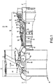
FIG. 1 illustrates an exemplary gas turbine engine, in accordance with various embodiments; -
FIG. 2 illustrates a stator vane having a shear tube, in accordance with various embodiments; -
FIG. 3A illustrates a cross section of a stator vane having a shear tube, in accordance with various embodiments; -
FIG. 3B illustrates a cross section of an airfoil having a shear tube, in accordance with various embodiments -
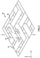
FIG. 4 illustrates a section of triaxially braided layer, in accordance with various embodiments; -
FIG. 5A illustrates a plurality of nominally dense plies of a CMC structure, in accordance with various embodiments; -
FIG. 5B illustrates a CMC structure comprising a plurality of nominally dense plies, in accordance with various embodiments; -
FIG. 6A illustrates a plurality of nominally dense plies of a CMC structure, in accordance with various embodiments; -
FIG. 6B illustrates a plurality of nominally dense plies of a CMC structure, in accordance with various embodiments -
FIG. 7A illustrates a plurality of nominally dense plies of a CMC structure, in accordance with various embodiments -
FIG. 7B illustrates a CMC structure comprising a plurality of nominally dense plies, in accordance with various embodiments -
FIG. 8 illustrates a CMC structure comprising a plurality of nominally dense plies, in accordance with various embodiments; and -
FIG. 9 illustrates a method of manufacturing a CMC structure, in accordance with various embodiments. - The detailed description of exemplary embodiments herein makes reference to the accompanying drawings, which show exemplary embodiments by way of illustration and their best mode. While these exemplary embodiments are described in sufficient detail to enable those skilled in the art to practice the disclosures, it should be understood that other embodiments may be realized and that logical, chemical, and mechanical changes may be made without departing from the spirit and scope of the disclosures. Thus, the detailed description herein is presented for purposes of illustration only and not of limitation. For example, the steps recited in any of the method or process descriptions may be executed in any order and are not necessarily limited to the order presented. Furthermore, any reference to singular includes plural embodiments, and any reference to more than one component or step may include a singular embodiment or step. Also, any reference to attached, fixed, connected or the like may include permanent, removable, temporary, partial, full and/or any other possible attachment option. Additionally, any reference to without contact (or similar phrases) may also include reduced contact or minimal contact.
- In various embodiments and with reference to
FIG. 1 , agas turbine engine 20 is provided.Gas turbine engine 20 may be a two-spool turbofan that generally incorporates afan section 22, acompressor section 24, acombustor section 26 and aturbine section 28. In operation,fan section 22 can drive air along a bypass flow-path B whilecompressor section 24 can drive air for compression and communication intocombustor section 26 then expansion throughturbine section 28. Although depicted as a turbofangas turbine engine 20 herein, it should be understood that the concepts described herein are not limited to use with turbofans as the teachings may be applied to other types of turbine engines including turbojet engines, low-bypass turbofans, high bypass turbofans, or any other gas turbine known to those skilled in the art. -
Gas turbine engine 20 may generally comprise alow speed spool 30 and ahigh speed spool 32 mounted for rotation about an engine central longitudinal axis A-A' relative to an enginestatic structure 36 via one or more bearing systems 38 (shown as bearing system 38-1 and bearing system 38-2). It should be understood that various bearingsystems 38 at various locations may alternatively or additionally be provided, including for example, bearingsystem 38, bearing system 38-1, and bearing system 38-2. -
Low speed spool 30 may generally comprise aninner shaft 40 that interconnects afan 42, a low pressure (or first) compressor section 44 (also referred to a low pressure compressor) and a low pressure (or first)turbine section 46.Inner shaft 40 may be connected to fan 42 through a gearedarchitecture 48 that can drivefan 42 at a lower speed thanlow speed spool 30.Geared architecture 48 may comprise agear assembly 60 enclosed within agear housing 62.Gear assembly 60 couplesinner shaft 40 to a rotating fan structure.High speed spool 32 may comprise anouter shaft 50 that interconnects a high pressure compressor ("HPC") 52 (e.g., a second compressor section) and high pressure (or second)turbine section 54. Acombustor 56 may be located betweenHPC 52 andhigh pressure turbine 54. Amid-turbine frame 57 of enginestatic structure 36 may be located generally betweenhigh pressure turbine 54 andlow pressure turbine 46.Mid-turbine frame 57 may support one ormore bearing systems 38 inturbine section 28.Inner shaft 40 andouter shaft 50 may be concentric and rotate via bearingsystems 38 about the engine central longitudinal axis A-A', which is collinear with their longitudinal axes. As used herein, a "high pressure" compressor or turbine experiences a higher pressure than a corresponding "low pressure" compressor or turbine. - The core airflow C may be compressed by
low pressure compressor 44 thenHPC 52, mixed and burned with fuel incombustor 56, then expanded overhigh pressure turbine 54 andlow pressure turbine 46.Mid-turbine frame 57 includesairfoils 59 which are in the core airflow path.Low pressure turbine 46, andhigh pressure turbine 54 rotationally drive the respectivelow speed spool 30 andhigh speed spool 32 in response to the expansion. -
Gas turbine engine 20 may be, for example, a high-bypass geared aircraft engine. In various embodiments, the bypass ratio ofgas turbine engine 20 may be greater than about six (6). In various embodiments, the bypass ratio ofgas turbine engine 20 may be greater than ten (10). In various embodiments, gearedarchitecture 48 may be an epicyclic gear train, such as a star gear system (sun gear in meshing engagement with a plurality of star gears supported by a carrier and in meshing engagement with a ring gear) or other gear system.Geared architecture 48 may have a gear reduction ratio of greater than about 2.3 andlow pressure turbine 46 may have a pressure ratio that is greater than about 5. In various embodiments, the bypass ratio ofgas turbine engine 20 is greater than about ten (10:1). In various embodiments, the diameter offan 42 may be significantly larger than that of thelow pressure compressor 44, and thelow pressure turbine 46 may have a pressure ratio that is greater than about (5:1).Low pressure turbine 46 pressure ratio may be measured prior to inlet oflow pressure turbine 46 as related to the pressure at the outlet oflow pressure turbine 46 prior to an exhaust nozzle. It should be understood, however, that the above parameters are exemplary of various embodiments of a suitable geared architecture engine and that the present disclosure contemplates other gas turbine engines including direct drive turbofans. - In various embodiments, the next generation of turbofan engines may be designed for higher efficiency which is associated with higher pressure ratios and higher temperatures in the
HPC 52. These higher operating temperatures and pressure ratios may create operating environments that may cause thermal loads that are higher than the thermal loads encountered in conventional turbofan engines, which may shorten the operational life of current components. - In various embodiments,
HPC 52 may comprise alternating rows of rotating rotors and stationary stators. Stators may have a cantilevered configuration or a shrouded configuration. More specifically, a stator may comprise a stator vane, a casing support and a hub support. In this regard, a stator vane may be supported along an outer diameter by a casing support and along an inner diameter by a hub support. In contrast, a cantilevered stator may comprise a stator vane that is only retained and/or supported at the casing (e.g., along an outer diameter). - In various embodiments, rotors may be configured to compress and spin a fluid flow. Stators may be configured to receive and straighten the fluid flow. In operation, the fluid flow discharged from the trailing edge of stators may be straightened (e.g., the flow may be directed in a substantially parallel path to the centerline of the engine and/or HPC) to increase and/or improve the efficiency of the engine and, more specifically, to achieve maximum and/or near maximum compression and efficiency when the straightened air is compressed and spun by a rotor.
- According to various embodiments and with reference to
FIGS. 1 and2 , a CMC structure may be a turbine engine component (e.g, a hot and/or cold section component) such asstator vane 200 manufactured according to the techniques described herein is illustrated with XYZ-axes provided for reference. Although depicted inFIG. 2 as a stator vane, the processes and techniques described herein are applicable to any number of CMC structures such as, for example, airfoils, blades, vanes, disks, nozzles, diffusers, combustors, seals, rotors, cases, heatshields, beams, plates, and/or any other suitable article of manufacture.Stator vane 200 comprises anairfoil 206 extending between an inner gas path surface 208 of a first platform 204 (i.e. an inner platform) and an outer gas path surface 210 of a second platform 202 (i.e. an outer platform).Airfoil 206 has a chord length defined between aleading edge 221 and a trailingedge 220. Thefirst platform 204 is defined between the inner gas path surface 208 andinner platform surface 214 and, in like regard, thesecond platform 202 is defined between the outer gas path surface 210 and theouter platform surface 212. In various embodiments, one or more cores such asfirst core 216 andsecond core 218 may extend radially (along the Z-axis) through theairfoil 206. Thecores outer platform surface 212 ofsecond platform 202 andinner platform surface 214 offirst platform 204. In this regard, theinner platform surface 214 and theouter platform surface 212 may be in fluid communication through thefirst core 216 andsecond core 218. Duringgas turbine engine 20 operation,stator vane 200 may experience compressive loading force Fc in the radial direction (along the Z-axis) and may also experience aerodynamic shear loading Fs in the XY-plane. - In various embodiments and with additional reference to
FIGs. 3A and3B ,stator vane 200 comprises a plurality of stacked, layered, and/or wrapped matrix plies and/or weaves.Stator vane 200 may be a Ceramic Matrix Composite (CMC) material such as, for example, one of a silicon-carbide/silicon-carbide matrix, carbon/carbon matrix, carbon/silicon-carbide matrix, alumina matrix, mullite matrix, or a zirconium diboride matrix. In various embodiments, a CMC material may comprise one or more of borides, carbides, oxides, and/or nitrides. In various embodiments the borides may be selected among a group comprising: ZrB2, HfB2, VB2, TiB2, TaB2, TaB, NbB2, NbB, VB2, TiB2, CrB2, Mo2B5, W2B5, Fe2B, FeB, Ni2B, NiB, LaB6, CoB, Co2B, or any other refractory boride. In various embodiments, the carbides may be selected among a group comprising: SiC, HfC, ZrC, C, B4C, SiOC, TiC, WC, Mo2C, TaC, NbC, or any other refractory carbide. In various embodiments, the oxides may be selected among a group comprising: HfO2, ZrO2, A1203, Si02, class compositions including aluminosilicates, borosilicates, lithium aluminosilicates (LAS), magnesium aluminosilicates, barium magnesium aluminosilicates (BMAS), calcium aluminosilicates and other silica containing high temperature glasses, and/or other mixed metal oxides. In various embodiments, the nitrides may be selected among a group comprising: AlN, Si3N4, TaN, TiN, TiAIN, W2N, WN, WN2, VN, ZrN, BN, HfN, NbN, or any other refractory nitrides. In various embodiments, the CMC material may comprise mixed refractory nonoxides such as, for example, SiCN. -
FIG. 3A illustratesstator vane 200 in partial cross section through the ZY plane viewed along the X-axis.FIG. 3B illustrates a cross section ofairfoil 206 ofstator vane 200 through the XY plane viewed along the Z-axis.First platform 204 comprises a first plurality of platform plies 308 layered relatively coplanar with the XY plane and stacked (along the Z-axis). In a like manner, thesecond platform 202 comprises a second plurality of platform plies 306 layered relatively coplanar with the XY plane and stacked (along the Z-axis). The platform plies 306 and 308 may tend to be relatively resistant to compressive loading Fc but, in response to shear loading Fs applied relatively in plane to the platform plies 306 and 308, may tend to delaminate. -
Airfoil 206 may be built up around one ormore shear tubes 300 which may define the circumference of thefirst core 216 and thesecond core 218.Shear tubes 300 may comprise one or more shear tube layers such as firstshear tube layer 302 and second shear tube layer 304 which wrap around the Z-axis and extend along the Z-axis through theairfoil 206, thefirst platform 204 and thesecond platform 202. Stated another way, theshear tubes 300 are disposed relatively orthogonally (i.e. within 45°) to the first plurality of platform plies 308 and the second plurality of platform plies 306. In this regard, theshear tubes 300 may be relatively orthogonal to thefirst platform 204 and thesecond platform 202 and tend to resist aerodynamic shear force Fs tending thereby to inhibit delamination of the first plurality of platform plies 308 and the second plurality of platform plies 306. In various embodiments, ashear tube 300 may be wrapped, braided, and/or a triaxially braided shear tube. -
Airfoil 206 may further include one or more overbraid layers which wrap around the Z-axis about theshear tubes 300 such asfirst overbraid layer 316 andsecond overbraid layer 320. In various embodiments, the overbraid layers may be a continuous overbraid (e.g., a tube) with first platform ends (316a, 320a) and second platform ends (316b, 320b) feathered out and laid relatively in plane with the first the first plurality of platform plies 308 and the second plurality of platform plies 306 thereby forming a portion of the respective platform. In like regard,airfoil 206 may include a woven overlay 322 (e.g., a Y-weave overlay) about the overbraid layers with ends (322a, 322b) of thewoven overlay 322 similarly feathered and laid relatively in plane with the first plurality of platform plies 308 and the second plurality of platform plies 306 and proximate first platform ends (316a, 320a) and second platform ends (316b, 320b). - An
aerodynamic layer 314 wraps over thewoven overlay 322, forming the aerodynamic surface ofairfoil 206 with ends (314a, 314b) similarly feathered and laid relatively in plane with the first plurality of platform plies 308 and the second plurality of platform plies 306 and respectively contacting the ends (322a, 322b) of thewoven overlay 322. In various embodiments,aerodynamic layer 314 may not fully overwrap thewoven overlay 322 and may expose aportion 324 of thewoven overlay 322 proximate the trailingedge 220 ofairfoil 206. In various embodiments an innergas path layer 312 may be layered overfirst platform end 314a ofaerodynamic layer 314 and define the innergas path surface 208. In like regard, an outergas path layer 310 may be layered over thesecond platform end 314b ofaerodynamic layer 314 and define the outergas path surface 210. In this regard,airfoil 206 may be built up of multiple layers and a shear tube such asshear tube 300 may comprise any layer or any number of layers of an airfoil such asairfoil 206. - With additional reference to
FIG. 4 , asection 400 of a triaxially braided layer is illustrated in accordance with various embodiments showing details of the braided fibers.Section 400 includes a plurality ofaxial fibers 402 which are wrapped relatively betweenfirst bias fibers 404 andsecond bias fibers 406. The intersection between thefirst bias fibers 404 and theaxial fibers 402 define a first bias angle α and, in like regard, the intersection between thesecond bias fibers 406 and theaxial fibers 402 define a second bias angle β. The first bias angle and the second bias angle may be configured to improve the material properties of a layer. In various embodiments, bias angle α and bias angle β may be equal. In various embodiments bias angle α may be between 20° and 70° and bias angle β may be between 20° and 70°. - In various embodiments, the first
shear tube layer 302 and the second shear tube layer 304 may comprise triaxially braided layers having theaxial fibers 402 oriented radially (parallel the Z-axis). In thisregard shear tube 300 may be a triaxially braided shear tube. In various embodiments,first overbraid layer 316 andsecond overbraid layer 320 may comprise triaxially braided layers having theaxial fibers 402 oriented axially (parallel the X-axis). In this regard, aerodynamic shear force Fs may be transferred compressively through the layers ofairfoil 206,first platform 204 andsecond platform 202 and, in response, tending to induce a bending and in plane shear force T in fibers (402, 404, 406) of the triaxially braidedshear tubes 300 which tends to resist the transmitted aerodynamic shear force Fs. In this regard, a closed section ofshear tubes 300 tends to increase its shear loading capacity thereby tending to enhance the overall shear strength of CMC structures such asvane 200. - With additional reference to
FIG. 5A a first plurality of nominallydense plies 500 of a CMC structure are illustrated and arranged for assembly. Each of the plies (502, 504, 506, 508, 510) may correspond, for example, to respectively adjacent layers of a CMC structure such asaerodynamic layer 314, wovenoverlay 322,second overbraid layer 320,first overbraid layer 316, and second shear tube layer 304. Each of the plies (502, 504, 506, 508, 510) are densified to a nominal density prior to arrangement for assembly. In various embodiments, the feedstock plies may be densified by any of those densification techniques known to those skilled in the art such as, for example, PIP, CVI, MI, Chemical Vapor Deposition (CVD), Atomic Layer Deposition (ALD), and/or the like. In a preferred but non-limiting embodiment, ALD may be used to enable a more complete densification of the feedstock plies. - The ALD process works by first adsorbing a nominal (mono)layer of a precursor on the surface(s) of a feedstock (e.g., a fiber based structure such as a ply, or layer, or a foam structure), purging the excess precursor, and then introducing a second reactant which converts the adsorbed layer to the desired chemistry. This results in a self-limiting, non-line-of-sight deposition of substantially uniform, pinhole-free, conformal coatings even on substrates with high aspect ratio (e.g. greater than 1000:1) features. The reaction conditions are chosen to achieve the best combination of precursor adsorption and subsequent reaction, with typical growth per cycle in the range of 0.5 to 1 Angstrom. Compositions can vary from metals to oxides and other ceramics (e.g. borides, carbides, nitrides and/or the like as described in paragraph [0028]), multilayer structures and even polymers such as, for example, by means of Molecular Layer Deposition (MLD). Although tending to have comparative low deposition rates to other densification processes, known ALD coating processes, such as for A1203, may be used to deposit several tens of microns of material. Additionally, a methodology known as 'spatial ALD' - whereby the feedstock moves through different reaction zones of a reactor (vs. 'temporal ALD' where the reactants are purged in/out of a reactor containing the feedstock) - may tend to increase throughput and tend to enable roll-to-roll processing having deposition rates on the order of microns per minute. In this regard, the plurality of nominally dense
single plies 500 may be produced utilizing higher throughput ALD techniques such as spatial ALD. In various embodiments, feedstocks may be densified via any suitable rapid processing densification technique in continuous and/or batch operations. - In various embodiments, the ALD process tends to enable substantially uniform build-up of material on exposed surfaces, throughout high aspect ratio substrates (including fibers, microcracks, and gaps) and even among several preform parts in a deposition chamber. Of the presently known densification processes discussed herein, it is believed that ALD tends to enable relatively the most uniform filling of a CMC structure (or any fiber, particulate, or other type of preform/substrate/feedstock) and therefore tends to inhibit 'canning off or maximize a reduction in the 'canning off of CMC feedstock based purely on geometric considerations. Stated another way, certain CMC feedstock preforms may possess geometries tending to promote densification at the feedstock surface, tending thereby to accelerate surface deposition and tending thereby to inhibit interior densification of the preform (e.g., by closing gas paths to the preform interior). In this regard, the interior of a preform may be 'canned off from the surface layers tending thereby to seal it from further densification.
- As compared to CVI, the deposition rate for ALD (with sufficient time for diffusion) does not change due to the process being an inherently self-limiting surface reaction. A CVD densification process, for example, may result in a density gradient from outside-in (i.e. greater purely from diffusional processes) and, due to geometrical constraints, may result in a more rapid reaction and 'canning-off' of a pore structure of the feedstock. In contrast, ALD tends to continue to uniformly and completely fill the pore structure due to being a series of self-limiting surface reactions which do not result in non-uniform nucleation and growth of the deposited material as is seen in CVI processes. In various embodiments, utilizing a reduced feedstock volume may tend to improve part densification. In various embodiments, the ALD process tends to enable manufacture of CMC structures with relatively higher fiber or other reinforcement (e.g. particulate) loading (i.e., structures comprising greater than 60% by volume fiber / other reinforcement) than the other densification processes described herein. In this regard, ALD densification of feedstock plies may tend to improve the mechanical properties of CMC structures. In various embodiments, feedstock plies may be cut to shape or laid up in a mold prior to densification thereby enabling production of nominally dense plies of arbitrary shape or curvature. For example, individual feedstock plies may be densified in a mold having the curvature of an airfoil to generate a nominally dense ply having an airfoil curvature.
- In various embodiments as shown in
FIG. 5B , each of the nominally dense plies (502, 504, 506, 508, 510) may be layered and bonded at contact interfaces relatively between each of the plies to form auniform CMC structure 512 comprising the bonded layers of nominally dense plies (502, 504, 506, 508, 510). For example ply 502 may be contacted withply 504 at a contact interface and bonded via at least one of a Field Assisted Sintering Technique (FAST), Spark Plasma Sintering (SPS), or similar method which facilitates localized heating at the contact interfaces to be bonded (i.e., a bonding interface). Each of the plies (502, 504, 506, 508, 510) may similarly be bonded via the localized heating bonding process to build up theCMC structure 512. In various embodiments, an interface layer may be applied between any or each of the plies (502, 504, 506, 508, 510) to promote FAST/SPS bonding and enhance interlaminar properties (e.g., mechanical, thermal, electrical, and/or the like) of theCMC structure 512. The interface layer may comprise a particulate, a chopped fiber, a nanotube, a slurry, and/or the like. Exemplary particulate compositions include those previously described for carbides, oxides, nitrides and borides, and include morphologies ranging from spherical or acicular to elongated, and sizes ranging from nanometer or submicron to tens of microns. Exemplary chopped fibers include carbon, silicon carbide, silicon nitride, silicon oxycarbide and oxides. Exemplary slurries may be aqueous or organic solvent based suspensions/dispersions of ceramic, metal or carbonaceous particulates. - With additional reference to
FIGs. 6A and 6B a second plurality of nominallydense plies 600 and a third plurality of nominallydense plies 602 are illustrated.Plies Plies 600 may be bonded to form a sandwich CMC structure defined by core plies 604 (shown in light shade) of a first CMC composition (e.g., a SiC/SiC composition) and face plies 606 (shown in dark shade) of a second CMC composition (e.g., an Ultra High Temperature Ceramic (UHTC) or Environmental Barrier Coating (EBC) / Thermal Barrier Coating (TBC) composition). In various embodiments, a CMC composition may include a monolithic ceramic composition (i.e., non-fiber reinforced). In various embodiments, the core plies may have an alternating fiber orientation whereby the axial fibers (e.g., axial fibers 400) of each of the respectively adjacent plies are set at a non-parallel relative angle. For example, a center core ply may be set as a zero angle (marked <0>) and the axial fibers of each of the respectively adjacent core plies may be orthogonal (marked <90>). -
Plies 602 may be bonded to form a gradated CMC structure defined by a gradation between a relatively lower temperature CMC composition and an UHTC CMC composition or EBC/TBC composition. The CMC composition of the plurality of plies may vary along a gradient (illustrated as lighter to darker shades of plies 602) defined from the low temperature CMC plies increasing to the high temperature CMC plies (e.g. an ultra high temperature CMC composition). In various embodiments a gradated CMC structure such as, for example, a combustor, may be optimized to include high temperature CMC compounds proximate a flame front and relatively lower temperature compounds away from the flame front. In another example, a turbine vane or blade may be optimized to comprise the UHTC composition proximate an aerodynamic surface (e.g., aerodynamic layer 314) and the relatively low temperature CMC plies proximate a core layer (e.g.,shear tubes 300,first overbraid layer 316, etc.) and a CMC composition gradient of high temperature material therebetween. In this regard, a CMC structure may be optimized for UTHC composition tending thereby to reduce production costs and time while tending to increase mechanical and thermal performance of the CMC structure. As will be appreciated by those skilled in the art, the gradation may be tailored for any number of desirable properties such as, for example coefficient of thermal expansion, mechanical properties such as toughness, hardness, strength, wear performance, density, etc. - In various embodiments and with reference to
FIGs. 7A and 7B a fourth plurality ofplies 700 is illustrated having first interply features 706 and second interply features 708.FIG. 7B illustrates an axial view along the interply features of aCMC structure 702 assembled of the plurality ofplies 700. The fourth plurality ofplies 700 has features, geometries, construction, materials, manufacturing techniques, and/or internal components similar toplies dense plies 704 of the plurality ofplies 700 may include interply (e.g., surface proximate and/or extending through the full ply thickness) features such as voids, machined features, additively manufactured features, or reinforcement features such as, for example, monofilament strands. For example, first interply features 706 may comprise cooling channels machined into the interlaminar face of the nominallydense ply 704. In another example, the second interply features 708 may comprise parallel monofilament strands laid along the interlaminar face of the nominallydense ply 704. - With additional reference to
FIG. 8 , aCMC structure 800 is illustrated having face bonded and edge bonded plies in accordance with various embodiments.CMC structure 800 comprises a plurality of plies having features, geometries, construction, materials, manufacturing techniques, and/or internal components similar toplies first face ply 804 and a second face ply 806 which are face bonded to thecore ply 802. Thefirst face ply 804 comprises a second CMC composition and thesecond face ply 806 comprises a third CMC composition. The core and face plies (802, 804, 806) extend axially from abase edge 814 to atip edge 816. Acap ply 808 may be edge bonded along thetip edge 816 of each of the core ply 802 thefirst face ply 804, and thesecond face ply 806. The cap ply 808 may comprise a fourth CMC composition. In various embodiments, a first longitudinal bolsterply 810 may be applied to the first face ply 804 proximate thebase edge 814. In like regard, a second longitudinal bolsterply 812 may be applied over second face ply 806 opposite the first longitudinal bolsterply 810 and proximate thebase edge 814. In various embodiments, the first longitudinal bolsterply 810 and the second longitudinal bolsterply 812 may comprise a fifth CMC composition. In this regard, a functionally graded CMC structure may be constructed of various CMC compositions. Any of the CMC compositions may include a monolithic ceramic composition. For example, a CMC structure including an airfoil may have a leading edge face ply of a CMC composition comprising a fine-grained monolithic ceramic for enhancing erosion and impact performance. - With additional reference to
FIG. 9 , amethod 900 of manufacturing a CMC structure may comprise densification of a feedstock ply to generate a nominally dense ply (step 902). In various embodiments, a nominally dense ply may have a density between 90% and 100% of the theoretical maximum density for a CMC composition selected for densification of the feedstock ply. Step 902 may include applying an interply feature to the nominally dense ply.Method 900 includes assembling a plurality of nominally dense plies to generate a preform structure (step 904). Step 904 may include layering two or more plies in a mold and applying an interface layer between the plies.Method 900 includes bonding the preform structure to generate a CMC structure (step 906). Step 906 includes bonding the preform structure via a FAST process, SPS process, and/or similar method which facilitates a localized heating at the bonding interface. Step 906 may include a second densification process subsequent to FAST/SPS bonding such as, for example, an ALD or CVD densification process. In various embodiments,method 900 includes at least one of finishing machining the CMC structure or applying a surface coating to the CMC structure to generate a finished CMC part. - Benefits, other advantages, and solutions to problems have been described herein with regard to specific embodiments. Furthermore, the connecting lines shown in the various figures contained herein are intended to represent exemplary functional relationships and/or physical couplings between the various elements. It should be noted that many alternative or additional functional relationships or physical connections may be present in a practical system. However, the benefits, advantages, solutions to problems, and any elements that may cause any benefit, advantage, or solution to occur or become more pronounced are not to be construed as critical, required, or essential features or elements of the disclosures.
- The scope of the disclosures is accordingly to be limited by nothing other than the appended claims, in which reference to an element in the singular is not intended to mean "one and only one" unless explicitly so stated, but rather "one or more." Moreover, where a phrase similar to "at least one of A, B, or C" is used in the claims, it is intended that the phrase be interpreted to mean that A alone may be present in an embodiment, B alone may be present in an embodiment, C alone may be present in an embodiment, or that any combination of the elements A, B and C may be present in a single embodiment; for example, A and B, A and C, B and C, or A and B and C. Different cross-hatching is used throughout the figures to denote different parts but not necessarily to denote the same or different materials.
- Systems, methods and apparatus are provided herein. In the detailed description herein, references to "one embodiment", "an embodiment", "an example embodiment", etc., indicate that the embodiment described may include a particular feature, structure, or characteristic, but every embodiment may not necessarily include the particular feature, structure, or characteristic. Moreover, such phrases are not necessarily referring to the same embodiment. Further, when a particular feature, structure, or characteristic is described in connection with an embodiment, it is submitted that it is within the knowledge of one skilled in the art to affect such feature, structure, or characteristic in connection with other embodiments whether or not explicitly described. After reading the description, it will be apparent to one skilled in the relevant art(s) how to implement the disclosure in alternative embodiment
- Furthermore, no element, component, or method step in the present disclosure is intended to be dedicated to the public regardless of whether the element, component, or method step is explicitly recited in the claims. No claim element is intended to invoke 35 U.S.C. 112(f) unless the element is expressly recited using the phrase "means for." As used herein, the terms "comprises", "comprising", or any other variation thereof, are intended to cover a non-exclusive inclusion, such that a process, method, article, or apparatus that comprises a list of elements does not include only those elements but may include other elements not expressly listed or inherent to such process, method, article, or apparatus.
Claims (14)
- A turbine engine component, comprising:a Ceramic Matrix Composite (CMC) structure including a plurality of nominally dense plies,wherein each of the plurality of nominally dense plies are bonded by at least one of a Field Assisted Sintering Technique (FAST), a Spark Plasma Sintering (SPS), or a localized heating at a bonding interface.
- The turbine engine component of claim 1, further comprising an airfoil extending between a first platform and a second platform,
wherein the airfoil, the first platform, and the second platform define the CMC structure. - The turbine engine component of claim 1 or 2, wherein at least one of the plurality of nominally dense plies comprises a monolithic ceramic composition.
- An article of manufacture, comprising:a Ceramic Matrix Composite (CMC) structure including a plurality of nominally dense plies,wherein each of the plurality of nominally dense plies are bonded by at least one of a Field Assisted Sintering Technique (FAST), a Spark Plasma Sintering (SPS), or a localized heating at a bonding interface.
- The article of manufacture of claim 4, wherein at least one of the plurality of nominally dense plies is densified to generate an airfoil curvature.
- The turbine engine component of claim 1, 2 or 3 or the article of manufacture of claim 4 or 5, wherein the plurality of nominally dense plies includes an interply feature.
- The turbine engine component or the article of manufacture of claim 6, wherein the interply feature comprises at least one of a cooling channel, a void, a machined feature, an additively manufactured feature, a monofilament strand, or a reinforcement feature.
- The turbine engine component of any of claims 1 to 3, 6 or 7 or the article of manufacture of any of claims 4 to 7, wherein the plurality of nominally dense plies includes an interface layer.
- The article of manufacture of claim 8, wherein the interface layer comprises at least one of a particulate, a chopped fiber, a nanotube, or a slurry.
- The turbine engine component of any of claims 1 to 3 or 6 to 8 or the article of manufacture of any of claims 4 to 9, wherein the CMC structure is characterized by a gradiation of a CMC composition of the plurality of plies along a gradient from an ultra high temperature CMC composition to a relatively lower temperature CMC composition.
- The turbine engine component of claim 10, wherein the gradation of the CMC composition is defined between an aerodynamic surface and a core layer of the turbine engine component.
- The article of manufacture of any of claims 4 to 10, wherein the CMC structure comprises one of face bonded and edge bonded nominally dense plies.
- The turbine engine component of any of claims 1 to 3 or 6 to 8, 10 or 11 or the article of manufacture of any of claims 4 to 10 or 12, wherein the CMC structure comprises greater than 60 percent by volume of fiber.
- A method of manufacturing a CMC structure, the method comprising:densifying a feedstock ply to generate a nominally dense ply;assembling a plurality of nominally dense plies to generate a preform structure; andbonding the preform structure via at least one of a Field Assisted Sintering Technique (FAST), a Spark Plasma Sintering (SPS) process, or a localized heating at a bonding interface.
Applications Claiming Priority (1)
| Application Number | Priority Date | Filing Date | Title |
|---|---|---|---|
| US16/361,040 US11414355B2 (en) | 2019-03-21 | 2019-03-21 | Systems and methods for additively manufactured ceramic composites |
Publications (1)
| Publication Number | Publication Date |
|---|---|
| EP3712122A1 true EP3712122A1 (en) | 2020-09-23 |
Family
ID=69804479
Family Applications (1)
| Application Number | Title | Priority Date | Filing Date |
|---|---|---|---|
| EP20162106.7A Pending EP3712122A1 (en) | 2019-03-21 | 2020-03-10 | Systems and methods for additively manufactured ceramic composites |
Country Status (2)
| Country | Link |
|---|---|
| US (1) | US11414355B2 (en) |
| EP (1) | EP3712122A1 (en) |
Cited By (6)
| Publication number | Priority date | Publication date | Assignee | Title |
|---|---|---|---|---|
| EP3922453A1 (en) * | 2020-06-11 | 2021-12-15 | Goodrich Corporation | Compliant interlayer |
| EP4105449A1 (en) * | 2021-06-18 | 2022-12-21 | Raytheon Technologies Corporation | Hybrid bonded configuration for blade outer airseal (boas) |
| US12037912B2 (en) | 2021-06-18 | 2024-07-16 | Rtx Corporation | Advanced passive clearance control (APCC) control ring produced by field assisted sintering technology (FAST) |
| US12055056B2 (en) | 2021-06-18 | 2024-08-06 | Rtx Corporation | Hybrid superalloy article and method of manufacture thereof |
| US12180120B2 (en) | 2019-05-17 | 2024-12-31 | Rtx Corporation | Rapid processing of laminar composite components |
| US12529316B2 (en) | 2021-06-18 | 2026-01-20 | Rtx Corporation | Bonding method for repair of superalloy article |
Families Citing this family (9)
| Publication number | Priority date | Publication date | Assignee | Title |
|---|---|---|---|---|
| US10034519B2 (en) | 2016-06-16 | 2018-07-31 | Adidas Ag | UV curable lattice microstructure for footwear |
| US11359507B2 (en) * | 2019-09-26 | 2022-06-14 | Raytheon Technologies Corporation | Double box composite seal assembly with fiber density arrangement for gas turbine engine |
| US11352897B2 (en) * | 2019-09-26 | 2022-06-07 | Raytheon Technologies Corporation | Double box composite seal assembly for gas turbine engine |
| US11719103B1 (en) * | 2022-04-07 | 2023-08-08 | General Electric Company | Components having composite laminate with co-cured chopped fibers |
| CN115286392B (en) * | 2022-08-05 | 2023-04-07 | 安徽工业大学 | Preparation of TiB 2 Method for preparing ternary complex phase ceramic of-TiC-SiC and its product |
| US12352173B2 (en) * | 2022-11-25 | 2025-07-08 | Rtx Corporation | Gas turbine engine with carbon/carbon composite piston seal |
| US12240144B2 (en) | 2023-04-14 | 2025-03-04 | Rtx Corporation | Method for CMC airfoil using core tube of rigidized ceramic fabric |
| US12467369B2 (en) | 2023-08-22 | 2025-11-11 | General Electric Company | Composite component having an additively printed inner portion |
| US12529320B1 (en) | 2024-09-10 | 2026-01-20 | Rtx Corporation | Partial shear tube y-weave trailing edge for a CMC vane and method therefor |
Citations (5)
| Publication number | Priority date | Publication date | Assignee | Title |
|---|---|---|---|---|
| US20010026868A1 (en) * | 1997-07-18 | 2001-10-04 | Ngk Insulators, Ltd. | Si-SiC material and SiC fiber-reinforced Si-SiC composite material |
| US20170320784A1 (en) * | 2015-12-08 | 2017-11-09 | Edward J.A. Pope | Fast-densified ceramic matrix composite and fabrication method |
| US9931818B1 (en) * | 2017-04-05 | 2018-04-03 | General Electric Company | Method for forming CMC article |
| US20180244583A1 (en) * | 2015-10-28 | 2018-08-30 | Sgl Carbon Se | Carbon fiber-reinforced carbide-ceramic composite component |
| US20180328189A1 (en) * | 2017-05-11 | 2018-11-15 | General Electric Company | Cmc components having microchannels and methods for forming microchannels in cmc components |
Family Cites Families (7)
| Publication number | Priority date | Publication date | Assignee | Title |
|---|---|---|---|---|
| US6627019B2 (en) * | 2000-12-18 | 2003-09-30 | David C. Jarmon | Process for making ceramic matrix composite parts with cooling channels |
| US7597838B2 (en) * | 2004-12-30 | 2009-10-06 | General Electric Company | Functionally gradient SiC/SiC ceramic matrix composites with tailored properties for turbine engine applications |
| FR2998295B1 (en) | 2012-11-20 | 2015-01-30 | Commissariat Energie Atomique | ALUMINOSILICATE MATRIX COMPOSITE MATERIAL, IN PARTICULAR "LOW" BARIUM ALUMINOSILICATE REINFORCED BY METAL OXIDE REINFORCING, AND PROCESS FOR PREPARING THE SAME. |
| US9957821B2 (en) * | 2013-03-01 | 2018-05-01 | United Technologies Corporation | Gas turbine engine composite airfoil trailing edge |
| US20150003997A1 (en) * | 2013-07-01 | 2015-01-01 | United Technologies Corporation | Method of forming hybrid metal ceramic components |
| CN105016759A (en) | 2015-07-01 | 2015-11-04 | 西北工业大学 | Rapid preparation method for C/SiC composite material |
| US10569481B2 (en) * | 2017-06-26 | 2020-02-25 | General Electric Company | Shaped composite ply layups and methods for shaping composite ply layups |
-
2019
- 2019-03-21 US US16/361,040 patent/US11414355B2/en active Active
-
2020
- 2020-03-10 EP EP20162106.7A patent/EP3712122A1/en active Pending
Patent Citations (5)
| Publication number | Priority date | Publication date | Assignee | Title |
|---|---|---|---|---|
| US20010026868A1 (en) * | 1997-07-18 | 2001-10-04 | Ngk Insulators, Ltd. | Si-SiC material and SiC fiber-reinforced Si-SiC composite material |
| US20180244583A1 (en) * | 2015-10-28 | 2018-08-30 | Sgl Carbon Se | Carbon fiber-reinforced carbide-ceramic composite component |
| US20170320784A1 (en) * | 2015-12-08 | 2017-11-09 | Edward J.A. Pope | Fast-densified ceramic matrix composite and fabrication method |
| US9931818B1 (en) * | 2017-04-05 | 2018-04-03 | General Electric Company | Method for forming CMC article |
| US20180328189A1 (en) * | 2017-05-11 | 2018-11-15 | General Electric Company | Cmc components having microchannels and methods for forming microchannels in cmc components |
Cited By (9)
| Publication number | Priority date | Publication date | Assignee | Title |
|---|---|---|---|---|
| US12180120B2 (en) | 2019-05-17 | 2024-12-31 | Rtx Corporation | Rapid processing of laminar composite components |
| EP3738768B1 (en) * | 2019-05-17 | 2026-04-08 | RTX Corporation | Rapid processing of laminar composite components |
| EP3922453A1 (en) * | 2020-06-11 | 2021-12-15 | Goodrich Corporation | Compliant interlayer |
| US12044279B2 (en) | 2020-06-11 | 2024-07-23 | Goodrich Corporation | Compliant interlayer |
| EP4105449A1 (en) * | 2021-06-18 | 2022-12-21 | Raytheon Technologies Corporation | Hybrid bonded configuration for blade outer airseal (boas) |
| US12037912B2 (en) | 2021-06-18 | 2024-07-16 | Rtx Corporation | Advanced passive clearance control (APCC) control ring produced by field assisted sintering technology (FAST) |
| US12055056B2 (en) | 2021-06-18 | 2024-08-06 | Rtx Corporation | Hybrid superalloy article and method of manufacture thereof |
| US12392252B2 (en) | 2021-06-18 | 2025-08-19 | Rtx Corporation | Hybrid bonded configuration for blade outer air seal (BOAS) |
| US12529316B2 (en) | 2021-06-18 | 2026-01-20 | Rtx Corporation | Bonding method for repair of superalloy article |
Also Published As
| Publication number | Publication date |
|---|---|
| US11414355B2 (en) | 2022-08-16 |
| US20200299200A1 (en) | 2020-09-24 |
Similar Documents
| Publication | Publication Date | Title |
|---|---|---|
| US11414355B2 (en) | Systems and methods for additively manufactured ceramic composites | |
| CN113006886B (en) | Ceramic matrix composite components including counterflow channels and methods of production | |
| US11391158B2 (en) | Composite airfoil assembly with separate airfoil, inner band, and outer band | |
| US10458260B2 (en) | Nozzle airfoil decoupled from and attached outside of flow path boundary | |
| CN113389600B (en) | Nozzle assembly with alternating guide vanes for a turbine engine | |
| US12351531B2 (en) | Protective coating for ceramic matrix composites | |
| US11015467B2 (en) | Porous space fillers for ceramic matrix composites | |
| JP6887454B2 (en) | Composite components with T or L-shaped joints and methods for forming them | |
| EP4299892B1 (en) | Ceramic matrix composite articles | |
| US10941665B2 (en) | Composite airfoil assembly for an interdigitated rotor | |
| EP4008702B1 (en) | Ceramic matrix composite with fibers having a specific coating | |
| US10364707B2 (en) | Retention assembly for gas turbine engine components | |
| US10677075B2 (en) | Composite airfoil assembly for an interdigitated rotor | |
| US10753232B2 (en) | Assemblies and methods for cooling flowpath support structure and flowpath components | |
| EP4631722A1 (en) | Composite panel and method of manufacturing | |
| CN108730035B (en) | Flow path assembly for a gas turbine engine and method of assembling the assembly | |
| CN108798793A (en) | For preventing fluid stream from passing through the interceptor in flow path gap |
Legal Events
| Date | Code | Title | Description |
|---|---|---|---|
| PUAI | Public reference made under article 153(3) epc to a published international application that has entered the european phase |
Free format text: ORIGINAL CODE: 0009012 |
|
| STAA | Information on the status of an ep patent application or granted ep patent |
Free format text: STATUS: THE APPLICATION HAS BEEN PUBLISHED |
|
| AK | Designated contracting states |
Kind code of ref document: A1 Designated state(s): AL AT BE BG CH CY CZ DE DK EE ES FI FR GB GR HR HU IE IS IT LI LT LU LV MC MK MT NL NO PL PT RO RS SE SI SK SM TR |
|
| AX | Request for extension of the european patent |
Extension state: BA ME |
|
| RAP1 | Party data changed (applicant data changed or rights of an application transferred) |
Owner name: RAYTHEON TECHNOLOGIES CORPORATION |
|
| STAA | Information on the status of an ep patent application or granted ep patent |
Free format text: STATUS: REQUEST FOR EXAMINATION WAS MADE |
|
| 17P | Request for examination filed |
Effective date: 20210323 |
|
| RBV | Designated contracting states (corrected) |
Designated state(s): AL AT BE BG CH CY CZ DE DK EE ES FI FR GB GR HR HU IE IS IT LI LT LU LV MC MK MT NL NO PL PT RO RS SE SI SK SM TR |
|
| STAA | Information on the status of an ep patent application or granted ep patent |
Free format text: STATUS: EXAMINATION IS IN PROGRESS |
|
| 17Q | First examination report despatched |
Effective date: 20230626 |
|
| RAP3 | Party data changed (applicant data changed or rights of an application transferred) |
Owner name: RTX CORPORATION |