EP3712064A1 - Structurally tunable cores - Google Patents
Structurally tunable cores Download PDFInfo
- Publication number
- EP3712064A1 EP3712064A1 EP20163440.9A EP20163440A EP3712064A1 EP 3712064 A1 EP3712064 A1 EP 3712064A1 EP 20163440 A EP20163440 A EP 20163440A EP 3712064 A1 EP3712064 A1 EP 3712064A1
- Authority
- EP
- European Patent Office
- Prior art keywords
- core members
- resilient core
- composite laminate
- flex beam
- segment
- Prior art date
- Legal status (The legal status is an assumption and is not a legal conclusion. Google has not performed a legal analysis and makes no representation as to the accuracy of the status listed.)
- Granted
Links
Images






Classifications
-
- B—PERFORMING OPERATIONS; TRANSPORTING
- B64—AIRCRAFT; AVIATION; COSMONAUTICS
- B64C—AEROPLANES; HELICOPTERS
- B64C27/00—Rotorcraft; Rotors peculiar thereto
- B64C27/32—Rotors
- B64C27/33—Rotors having flexing arms
-
- B—PERFORMING OPERATIONS; TRANSPORTING
- B64—AIRCRAFT; AVIATION; COSMONAUTICS
- B64C—AEROPLANES; HELICOPTERS
- B64C1/00—Fuselages; Constructional features common to fuselages, wings, stabilising surfaces or the like
- B64C1/06—Frames; Stringers; Longerons ; Fuselage sections
- B64C1/12—Construction or attachment of skin panels
-
- B—PERFORMING OPERATIONS; TRANSPORTING
- B64—AIRCRAFT; AVIATION; COSMONAUTICS
- B64C—AEROPLANES; HELICOPTERS
- B64C27/00—Rotorcraft; Rotors peculiar thereto
- B64C27/001—Vibration damping devices
-
- B—PERFORMING OPERATIONS; TRANSPORTING
- B64—AIRCRAFT; AVIATION; COSMONAUTICS
- B64C—AEROPLANES; HELICOPTERS
- B64C27/00—Rotorcraft; Rotors peculiar thereto
- B64C27/32—Rotors
- B64C27/46—Blades
- B64C27/473—Constructional features
- B64C27/48—Root attachment to rotor head
-
- B—PERFORMING OPERATIONS; TRANSPORTING
- B64—AIRCRAFT; AVIATION; COSMONAUTICS
- B64C—AEROPLANES; HELICOPTERS
- B64C27/00—Rotorcraft; Rotors peculiar thereto
- B64C27/001—Vibration damping devices
- B64C2027/003—Vibration damping devices mounted on rotor hub, e.g. a rotary force generator
Definitions
- This disclosure relates generally to structural cores and, more specifically, to structurally tunable cores that can be implemented, for example, in aircraft components.
- bird wings include a highly integrated muscular and skeletal structure that advantageously enables the wings to operate over a large range of motion with variable stiffness.
- Known efforts to implement a biomimetic solution for aircraft components e.g., rotors, wings, etc.
- aircraft components e.g., rotors, wings, etc.
- mimics the operational capabilities associated with bird wings have long been hampered by limitations in designs, structural analyses, and material capabilities.
- flex beams in an aircraft rotor can advantageously replace complex hinges that would otherwise be required to couple the blades of the aircraft rotor to the hub of the aircraft rotor.
- Known flex beam implementations are limited, however, in terms of the degree and/or extent of vertical deflection (e.g., flapping) that is attainable via the flex beam while maintaining adequate chordwise and spanwise stiffnesses via the flex beam.
- a flex beam for coupling a rotor blade to a rotor hub is disclosed.
- the flex beam comprises a first composite laminate, a second composite laminate, a third composite laminate, first resilient core members, and second resilient core members.
- the first composite laminate forms a first skin of the flex beam.
- the second composite laminate is located opposite the first composite laminate and forms a second skin of the flex beam.
- the third composite laminate is located between the first composite laminate and the second composite laminate.
- the first resilient core members extend between the first composite laminate and the third composite laminate.
- the second resilient core members extend between the second composite laminate and the third composite laminate.
- an apparatus comprising a first composite laminate, a second composite laminate, a third composite laminate, first resilient core members, and second resilient core members.
- the first composite laminate forms a first skin.
- the second composite laminate is located opposite the first composite laminate and forms a second skin.
- the third composite laminate is located between the first composite laminate and the second composite laminate.
- the first resilient core members extend between the first composite laminate and the third composite laminate.
- the second resilient core members extend between the second composite laminate and the third composite laminate.
- a hybrid elastomeric bearing comprises a first annulus, a second annulus, resilient core members, a first elastomeric member, and a second elastomeric member.
- the second annulus circumscribes the first annulus.
- the resilient core members are arranged about a circumference of the first annulus and extend radially outwardly from the first annulus to the second annulus.
- respective ones of the resilient core members are spaced apart from one another and include a first segment, a second segment, and a third segment.
- the second segment extends from the first segment in a first direction defined by a first radius of curvature between the first and second segments.
- the third segment extends from the second segment in a second direction defined by a second radius of curvature between the second and third segments.
- the first elastomeric member extends between first neighboring ones of the resilient core members.
- the second elastomeric member extends between second neighboring ones of the resilient core members.
- the second neighboring ones are spaced apart from the first neighboring ones.
- a non-pneumatic tire comprises a hub, a rim, and resilient core members.
- the rim circumscribes the hub.
- the resilient core members are arranged about a circumference of the hub and extend radially outwardly from the hub to the rim.
- respective ones of the resilient core members are spaced apart from one another and include a first segment, a second segment, and a third segment.
- the second segment extends from the first segment in a first direction defined by a first radius of curvature between the first and second segments.
- the third segment extends from the second segment in a second direction defined by a second radius of curvature between the second and third segments.
- bird wings include a highly integrated muscular and skeletal structure that advantageously enables the wings to operate over a large range of motion with variable stiffness.
- Known efforts to implement a biomimetic solution for aircraft components e.g., rotors, wings, etc.
- aircraft components e.g., rotors, wings, etc.
- mimics the operational capabilities associated with bird wings have long been hampered by limitations in designs, structural analyses, and material capabilities.
- flex beams in an aircraft rotor can advantageously replace complex hinges that would otherwise be required to couple the blades of the aircraft rotor to the hub of the aircraft rotor.
- Known flex beam implementations e.g., as described below in connection with FIGS. 2 and 3
- the degree and/or extent of vertical deflection e.g., flapping
- FIG. 1 is a partial cutaway perspective view of a known aircraft rotor 100 having a flex beam 102.
- the flex beam 102 of FIG. 1 couples a rotor blade 104 of the aircraft rotor 100 to a rotor hub 106 of the aircraft rotor 100.
- the rotor blade 104 of FIG. 1 has a chord and a span. The chord of the rotor blade 104 extends along the x-axis 108 shown in FIG. 1 , and the span of the rotor blade 104 extends along the y-axis 110 shown in FIG. 1 .
- first stiffness e.g., a chordwise stiffness
- second stiffness e.g., a spanwise stiffness
- third stiffness e.g., a flapwise stiffness
- the flex beam 102 of FIG. 1 is structured, configured and/or arranged to have a third stiffness that facilitates a corresponding extent and/or degree of flapwise deflection of the flex beam 102 along the z-axis 112, and/or a corresponding extent and/or degree of flapwise deflection of the rotor blade 104 relative to the rotor hub 106 along the z-axis 112.
- Known implementations of the flex beam 102 of FIG. 1 are limited and/or restrictive in terms of the extent and/or degree of flapwise deflection that is attainable along the z-axis 112 while maintaining sufficient chordwise and/or spanwise stiffnesses of the flex beam 102 along the x-axis 108 and the y-axis 110.
- FIG. 2 is a cross-sectional view of a known configuration of independent plates 200 for implementing a flex beam (e.g., the flex beam 102 of FIG. 1 ).
- the independent plates 200 of FIG. 2 include a first plate 202 (e.g., an upper plate), a second plate 204 (e.g., a central plate), and a third plate 206 (e.g., a lower plate).
- the first plate 202 of FIG. 2 has a first end 208 and a second end 210 located opposite the first end 208.
- the second plate 204 of FIG. 2 has a first end 212 and a second end 214 located opposite the first end 212.
- first end 216 and a second end 218 located opposite the first end 216.
- first end 212 of the second plate 204 is aligned with the first end 208 of the first plate 202, and the second end 214 of the second plate 204 extends past the second end 210 of the first plate 202.
- first end 216 of the third plate 206 is aligned with the first end 212 of the second plate 204, and the second end 218 of the third plate 206 extends past the second end 214 of the second plate 204.
- the independent plates 200 of FIG. 2 have several disadvantages when implemented as a flex beam to couple a rotor blade to a rotor hub.
- the independent plates 200 can provide a relatively high extent and/or degree of flapwise deflection, such deflection often results in undesirable buckling of the first plate 202, the second plate 204, and/or the third plate 206 of the independent plates 200.
- Another disadvantage is that the independent plates 200 of FIG. 2 lack a shear path between the first plate 202, the second plate 204, and/or the third plate 206.
- FIG. 3 is a cross-sectional view of a known configuration of unified plates 300 for implementing a flex beam (e.g., the flex beam 102 of FIG. 1 ).
- the unified plates 300 of FIG. 3 include a first plate 302 (e.g., an upper plate), a second plate 304 (e.g., a central plate), and a third plate 306 (e.g., a lower plate).
- the first plate 302 of FIG. 3 has a first end 308 and a second end 310 located opposite the first end 308.
- the second plate 304 of FIG. 3 has a first end 312 and a second end 314 located opposite the first end 312.
- first end 316 and a second end 318 located opposite the first end 316.
- first end 312 of the second plate 304 is aligned with the first end 308 of the first plate 302, and the second end 314 of the second plate 304 extends past the second end 310 of the first plate 302.
- first end 316 of the third plate 306 is aligned with the first end 312 of the second plate 304, and the second end 318 of the third plate 306 extends past the second end 314 of the second plate 304.
- the unified plates 300 of FIG. 3 also have disadvantages when implemented as a flex beam to couple a rotor blade to a rotor hub.
- the unified plates 300 of FIG. 3 provide a rigid shear path between the first plate 302, the second plate 304, and/or the third plate 306, the unified plates 300 provide a far lower extent and/or degree of flapwise deflection relative to that attainable via the independent plates 200 of FIG. 2 described above.
- the structurally tunable cores disclosed herein facilitate a newly-attainable design space that enables the fabrication of components and/or structures (e.g., aircraft components and/or structures) which can be tuned, configured, customized and/or optimized based on desired operational capabilities (e.g., stiffnesses, deflections, etc.).
- the structurally tunable cores disclosed herein can be used to implement flex beams that advantageously enable a relatively high degree and/or extent of vertical deflection (flapping) to be attained while maintaining adequate chordwise and spanwise stiffnesses.
- the increased degree and/or extent of vertical deflection provided by the disclosed structurally tunable cores advantageously reduces the degree and/or extent of drag associated with the aircraft rotor (e.g., drag associated with the rotating blades of the aircraft rotor), and also advantageously reduces the degree and/or extent of maintenance associated with the aircraft rotor.
- the disclosed structurally tunable cores can advantageously be implemented in a variety of components and/or structures including, for example, the flex beams, the hybrid elastomeric bearings, and the non-pneumatic tires disclosed herein.
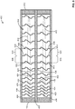
- FIG. 4 is a cross-sectional view of an example flex beam 400 including an example structurally tunable core 402 configured in an example first configuration.
- the structurally tunable core 402 and/or, more generally, the flex beam 400 is shown in an example neutral position.
- FIG. 5 is a cross-sectional view of the example flex beam of FIG. 4 in an example deflected position.
- the flex beam 400 is movable (e.g., deflectable and/or deformable) between the example neutral position shown in FIG. 4 and the example deflected position shown in FIG. 5 .
- the flex beam 400 of FIGS. 4 and 5 can be implemented as a mechanism to couple a rotor blade to a rotor hub (e.g., to couple the rotor blade 104 of FIG. 1 to the rotor hub 106 of FIG. 1 ).
- the flex beam 400 includes an example first composite laminate 404, an example second composite laminate 406, an example third composite laminate 408, an example first end 410, an example second end 412, and the structurally tunable core 402.
- the structurally tunable core 402 includes example first resilient core members 414 and example second resilient core members 416.
- the structurally tunable core 402 of FIGS. 4 and 5 can include fewer or additional sets of the resilient core members, and the flex beam 400 of FIGS. 4 and 5 can include fewer or additional ones of the composite laminates.
- the first composite laminate 404 forms an example first skin 418 (e.g., an upper skin) of the flex beam 400.
- the second composite laminate 406 is located opposite the first composite laminate 404 and forms an example second skin 420 (e.g., a lower skin) of the flex beam 400.
- the third composite laminate 408 is located between the first composite laminate 404 and the second composite laminate 406.
- the second end 412 of the flex beam 400 of FIGS. 4 and 5 is located opposite the first end 410 of the flex beam 400.
- the first composite laminate 404, the second composite laminate 406, and the third composite laminate 408 of the flex beam 400 of FIGS. 4 and 5 respectively extend from the first end 410 of the flex beam 400 to the second end 412 of the flex beam 400.
- the first composite laminate 404 and the second composite laminate 406 of the flex beam 400 of FIGS. 4 and 5 are respectively structured, configured and/or arranged to carry bending, chord, and torsional loads associated with the flex beam 400.
- the third composite laminate 408 of the flex beam 400 of FIGS. 4 and 5 is structured, configured and/or arranged to carry centrifugal loads associated with the flex beam 400.
- the flex beam 400 of FIGS. 4 and 5 may encounter such bending, chord, torsional and/or centrifugal loads when the flex beam 400 is implemented, for example, as a mechanism to couple a rotor blade to a rotor hub (e.g., to couple the rotor blade 104 of FIG. 1 to the rotor hub 106 of FIG. 1 ).
- the first composite laminate 404, the second composite laminate 406, and the third composite laminate 408 are substantially parallel to one another. In other examples, one or more of the first composite laminate 404, the second composite laminate 406, and/or the third composite laminate 408 of the flex beam 400 can be non-parallel and/or arranged at an angle relative to one another. In the illustrated example of FIGS. 4 and 5 , the first composite laminate 404, the second composite laminate 406, and the third composite laminate 408 are substantially linear. In other examples, one or more of the first composite laminate 404, the second composite laminate 406, and/or the third composite laminate 408 of the flex beam 400 can include one or more non-linear (e.g., curved) segments.
- the structurally tunable core 402 of the flex beam 400 of FIGS. 4 and 5 includes the first resilient core members 414 and the second resilient core members 416.
- the first resilient core members 414 of the structurally tunable core 402 of FIGS. 4 and 5 respectively extend between the first composite laminate 404 of the flex beam 400 and the third composite laminate 408 of the flex beam 400.
- Respective ones of the first resilient core members 414 are spaced apart from one another in a direction extending between the first end 410 and the second end 412 of the flex beam 400.
- the second resilient core members 416 of the structurally tunable core 402 of FIGS. 4 and 5 respectively extend between the second composite laminate 406 of the flex beam 400 and the third composite laminate 408 of the flex beam 400.
- Respective ones of the second resilient core members 416 are spaced apart from one another in a direction extending between the first end 410 and the second end 412 of the flex beam 400.
- the third composite laminate 408 of the flex beam 400 of FIGS. 4 and 5 separates and/or spaces apart the second resilient core members 416 from the first resilient core members 414 in a direction extending between the first composite laminate 404 and the second composite laminate 406 of the flex beam 400.
- each one of the first resilient core members 414 includes an example first end 422 coupled to the first composite laminate 404 of the flex beam 400, and an example second end 424 located opposite the first end 422 and coupled to the third composite laminate 408 of the flex beam 400.
- the first end 422 of each one of the first resilient core members 414 is integrally formed (e.g., as a single-piece, joint-free structure) with the first composite laminate 404.
- the first end 422 of each one of the first resilient core members 414 is coupled to the first composite laminate 404 of the flex beam 400 via a corresponding pi joint (e.g., the pi joint 700 of FIG.
- the pi joints are bonded and/or mechanically fastened to the interior surface 426 of the first composite laminate 404.
- the pi joints are integrally formed with the first composite laminate 404 along the interior surface 426 of the first composite laminate 404.
- the second end 424 of each one of the first resilient core members 414 is integrally formed (e.g., as a single-piece, joint-free structure) with the third composite laminate 408.
- the second end 424 of each one of the first resilient core members 414 is coupled to the third composite laminate 408 of the flex beam 400 via a corresponding pi joint (e.g., the pi joint 700 of FIG. 7 described below) located along an example first surface 428 (e.g., an upper surface) of the third composite laminate 408.
- the pi joints are bonded and/or mechanically fastened to the first surface 428 of the third composite laminate 408.
- the pi joints are integrally formed with the third composite laminate 408 along the first surface 428 of the third composite laminate 408.
- each one of the second resilient core members 416 includes an example first end 430 coupled to the second composite laminate 406 of the flex beam 400, and an example second end 432 located opposite the first end 430 and coupled to the third composite laminate 408 of the flex beam 400.
- the first end 430 of each one of the second resilient core members 416 is integrally formed (e.g., as a single-piece, joint-free structure) with the second composite laminate 406.
- the first end 430 of each one of the second resilient core members 416 is coupled to the second composite laminate 406 of the flex beam 400 via a corresponding pi joint (e.g., the pi joint 700 of FIG.
- the pi joints are bonded and/or mechanically fastened to the interior surface 434 of the second composite laminate 406. In other such examples, the pi joints are integrally formed with the second composite laminate 406 along the interior surface 434 of the second composite laminate 406.
- the second end 432 of each one of the second resilient core members 416 is integrally formed (e.g., as a single-piece, joint-free structure) with the third composite laminate 408.
- the second end 432 of each one of the second resilient core members 416 is coupled to the third composite laminate 408 of the flex beam 400 via a corresponding pi joint (e.g., the pi joint 700 of FIG. 7 described below) located along an example second surface 436 (e.g., a lower surface) of the third composite laminate 408, wherein the second surface 436 of the third composite laminate 408 is located opposite the first surface 428 (e.g., the upper surface) of the third composite laminate 408.
- the pi joints are bonded and/or mechanically fastened to the second surface 436 of the third composite laminate 408.
- the pi joints are integrally formed (e.g., as a single-piece, joint-free structure) with the third composite laminate 408 along the second surface 436 of the third composite laminate 408.
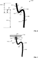
- FIG. 6 is a cross-sectional side view of an example resilient core base element 600 that is structurally tunable.
- the resilient core base element 600 of FIG. 6 can be used to implement one or more portion(s) and/or the entirety of any of the first resilient core member(s) 414 and/or any of the second resilient core member(s) 416 of the structurally tunable core 402 of FIGS. 4 and 5 .
- the resilient core base element 600 of FIG. 6 can be formed from any type(s) of material(s) (e.g., metals, plastics, composites, etc.) that enable the fabricated resilient core base member to have resilient (e.g., spring-like) deflection properties.
- the profile of the resilient core base element 600 is generally S-shaped.
- the profile of the resilient core base element 600 may be of a different shape relative to that shown in FIG. 6 including, for example, O-shaped, A-shaped, circular, elliptical, triangular, etc.
- the profile of the resilient core base element 600 may be configured (e.g., sized and/or shaped) in any manner that enables the fabricated resilient core base member 600 to have resilient (e.g., spring-like) deflection properties.
- the resilient core base element 600 includes an example first segment 602, an example second segment 604, and an example third segment 606.
- the first segment 602 of FIG. 6 has an example first height 608 and an example first thickness 610.
- the second segment 604 of FIG. 6 has an example second height 612 and an example second thickness 614.
- the third segment 606 of FIG. 6 has an example third height 616 and an example third thickness 618.
- the second segment 604 extends from the first segment 602 in a first direction defined by an example first radius of curvature 620 between the first segment 602 and the second segments 604.
- the third segment 606 extends from the second segment 604 in a second direction defined by an example second radius of curvature 622 between the second segment 604 and the third segment 606.
- the resilient core base element 600 of FIG. 6 is a base construction element that can be duplicated, and/or that can be expanded upon by the introduction of one or more additional segment(s).
- each one of the first resilient core members 414 of FIGS. 4 and 5 includes a first segment corresponding to the first segment 602 of FIG. 6 , a second segment corresponding to the second segment 604 of FIG. 6 , a third segment corresponding to the third segment 606 of FIG. 6 , a fourth segment extending from the third segment in a third direction defined by a third radius of curvature between the fourth segment and the third segment, and a fifth segment extending from the fourth segment in a fourth direction defined by a fourth radius of curvature between the fifth segment and the fourth segment.
- each one of the first resilient core members 414 of FIGS. 4 and 5 is in effect a duplication of the resilient core base element 600 of FIG. 6 .
- the heights, thicknesses, and radii of curvature associated with the first segment 602, the second segment 604, the third segment 606 and/or, more generally, the resilient core base element 600 define a tunable and/or configurable structural profile of the resilient core base element 600.
- Respective ones of the heights, the thicknesses, and the radii of curvature of the structural profile of the resilient core base element 600 of FIG. 6 can be individually or collectively configured, tuned and/or tailored to satisfy any one of a plethora of design requirements (e.g., stiffness requirements, deflection requirements, etc.) that may be associated with a particular implementation (e.g., a flex beam implementation).
- respective ones of the heights of the resilient core base element 600 of FIG. 6 can be individually or collectively configured.
- the first height 608 of the first segment 602 is greater than the second height 612 of the second segment 604
- the second height 612 of the second segment 604 is less than the third height 616 of the third segment 606
- the third height 616 of the third segment 606 is greater than the first height 608 of the first segment 602
- the overall height of the resilient core base element 600 has a first height value.
- the first height 608 is greater than the second height 612
- the second height 612 is less than the third height 616
- the third height 616 is greater than the first height 608, and the overall height of the resilient core base element 600 has a second height value that is greater than or less than the first height value.
- the respective relationships between and/or among one or more of the first height 608, the second height 612 and/or the third height 616 can differ relative to the relationships shown in FIG. 6 and described above.
- one or more of the first height 608, the second height 612 and/or the third height 616 can be substantially uniform (e.g., substantially equal to one another).
- respective ones of the thicknesses of the resilient core base element 600 of FIG. 6 can be individually or collectively configured.
- the first thickness 610 of the first segment 602, the second thickness 614 of the second segment 604, and the third thickness 618 of the third segment 606 are substantially uniform (e.g., substantially equal to one another) and have a first thickness value.
- the first thickness 610, the second thickness 614, and the third thickness 618 can be substantially uniform (e.g., substantially equal to one another) and have a second thickness value that is greater than or less than the first thickness value.
- one or more of the first thickness 610, the second thickness 614, and/or the third thickness 618 can have a first thickness value that differ(s) from a second thickness value of one or more other one(s) of the first thickness 610, the second thickness 614, and/or the third thickness 618.
- respective ones of the radii of curvature between the segments of the resilient core base element 600 of FIG. 6 can be individually or collectively configured.
- the first radius of curvature 620 between the first segment 602 and the second segment 604, and the second radius of curvature 622 between the second segment 604 and the third segment 606 are substantially uniform (e.g., substantially equal to one another) and have a first radius of curvature value.
- the first radius of curvature 620 and the second radius of curvature 622 can be substantially uniform (e.g., substantially equal to one another) and have a second radius of curvature value that is greater than or less than the first radius of curvature value.
- the first radius of curvature 620 can have a first radius of curvature value that differs from a second radius of curvature value of the second radius of curvature 622.
- respective ones of the widths of the segments of the resilient core base element 600 of FIG. 6 can be individually or collectively configured.
- a first width of the first segment 602, a second width of the second segment 604, and a third width of the third segment 606 can be substantially uniform (e.g., substantially equal to one another) and have a first width value.
- the first width, the second width, and the third width can be substantially uniform (e.g., substantially equal to one another) and have a second width value that is greater than or less than the first width value.
- one or more of the first width, the second width, and/or the third width can have a first width value that differ(s) from a second width value of one or more other one(s) of the first width, the second width, and/or the third width.
- the highly-tunable and/or highly-configurable nature of the resilient core base element 600 of FIG. 6 advantageously expands the design space for flex beams relative to the known flex beam designs of FIGS. 2 and 3 described above.
- known flex beam design techniques commonly involve stacking worst-case flight loads on top of worst-case environmental conditions on top of worst-case material allowables, etc., and then searching for higher strain or higher strength materials to design for such conservatisms and/or requirements in order to prove the safety and/or efficacy of a proposed design.
- suitable materials either do not yet exist or would be too cost prohibitive to manufacture.
- FIG. 7 is a cross-sectional view of the example resilient core base element 600 of FIG. 6 coupled to an example pi joint 700.
- the pi joint 700 includes an example base 702, and further includes example arms 704 extending at an angle from the base 702 and forming an example slot 706.
- the slot 706 of the pi joint 700 is configured (e.g., sized, shaped and/or arranged) to receive an example end 708 of the resilient core base element 600 to couple the resilient core base element 600 to the pi joint 700 and/or to a structure to which the pi joint 700 is coupled.
- the base 702 of the pi joint 700 can be bonded and/or mechanically fastened to another structure (e.g., the first composite laminate 404, the second composite laminate 406, or the third composite laminate 408 of FIGS. 4 and 5 , etc.).
- the base 702 and/or, more generally, the pi joint 700 can be integrally formed with another structure (e.g., the first composite laminate 404, the second composite laminate 406, or the third composite laminate 408 of FIGS. 4 and 5 , etc.).
- respective ones of the first resilient core members 414 of the structurally tunable core 402 have corresponding respective first structural profiles including first heights, first thicknesses, and first radii of curvature.
- Respective ones of the second resilient core members 416 of the structurally tunable core 402 have corresponding respective second structural profiles including second heights, second thicknesses, and second radii of curvature.
- the structurally tunable core 402 is shown configured in a first configuration.
- respective ones of the first resilient core members 414 are uniformly spaced apart from one another moving from the first end 410 toward the second end 412 of the flex beam 400.
- an example first one 438 of the first resilient core members 414 is separated from an example second one 440 of the first resilient core members 414 by an example first distance 442
- the second one 440 of the first resilient core members 414 is separated from an example third one 444 of the first resilient core members 414 by an example second distance 446 that is equal to the first distance 442.
- respective ones of the second resilient core members 416 are also uniformly spaced apart from one another moving from the first end 410 toward the second end 412 of the flex beam 400.
- an example first one 448 of the second resilient core members 416 is separated from an example second one 450 of the second resilient core members 416 by an example third distance 452
- the second one 450 of the second resilient core members 416 is separated from an example third one 454 of the second resilient core members 416 by an example fourth distance 456 that is equal to the third distance 452.
- the first distance 442, the second distance 446, the third distance 452, and the fourth distance 456 are equal to one another.
- the second distance 446 can be equal to the first distance 442
- the fourth distance 456 can be equal to the third distance 452
- the third distance 452 can differ from the first distance 442.
- the first structural profiles of the first resilient core members 414 are uniform relative to one another
- the second structural profiles of the second resilient core members 416 are uniform relative to one another
- the second structural profiles of the second resilient core members 416 match (e.g., are the same as) the first structural profiles of the first resilient core members 414.
- respective ones of the first resilient core members 414 can have differing and/or varying first structural profiles relative to one another
- respective ones of the second resilient core members 416 can have differing and/or varying second structural profiles relative to one another
- respective ones of the second resilient core members 416 can have uniform second structural profiles that differ and/or vary relative to uniform first structural profiles of respective ones of the first resilient core members 414.
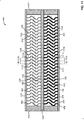
- FIG. 8 is a cross-sectional view of the example flex beam 400 of FIGS. 4 and 5 including the example structurally tunable core 402 of FIGS. 4 and 5 configured in an example second configuration.
- respective ones of the first resilient core members 414 are spaced apart from one another by a gradually increasing distance moving from the first end 410 toward the second end 412 of the flex beam 400.
- an example first one 802 of the first resilient core members 414 is separated from an example second one 804 of the first resilient core members 414 by an example first distance 806, and the second one 804 of the first resilient core members 414 is separated from an example third one 808 of the first resilient core members 414 by an example second distance 810 that is greater than the first distance 806.
- respective ones of the second resilient core members 416 are also spaced apart from one another by a gradually increasing distance moving from the first end 410 toward the second end 412 of the flex beam 400.
- an example first one 812 of the second resilient core members 416 is separated from an example second one 814 of the second resilient core members 416 by an example third distance 816
- the second one 814 of the second resilient core members 416 is separated from an example third one 818 of the second resilient core members 416 by an example fourth distance 820 that is greater than the third distance 816.
- the third distance 816 is equal to the first distance 806, and the fourth distance 820 is equal to the second distance 810.
- the third distance 816 can differ from the first distance 806, and/or the fourth distance 820 can differ from the second distance 810.
- the first structural profiles of the first resilient core members 414 are uniform relative to one another
- the second structural profiles of the second resilient core members 416 are uniform relative to one another
- the second structural profiles of the second resilient core members 416 match (e.g., are the same as) the first structural profiles of the first resilient core members 414.
- respective ones of the first resilient core members 414 can have differing and/or varying first structural profiles relative to one another
- respective ones of the second resilient core members 416 can have differing and/or varying second structural profiles relative to one another
- respective ones of the second resilient core members 416 can have uniform second structural profiles that differ and/or vary relative to uniform first structural profiles of respective ones of the first resilient core members 414.
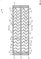
- FIG. 9 is a cross-sectional view of the example flex beam 400 of FIGS. 4 , 5 and 8 including the example structurally tunable core 402 of FIGS. 4 , 5 and 8 configured in an example third configuration.
- respective ones of the first resilient core members 414 are uniformly spaced apart from one another moving from the first end 410 toward the second end 412 of the flex beam 400.
- an example first one 902 of the first resilient core members 414 is separated from an example second one 904 of the first resilient core members 414 by an example first distance 906, and the second one 904 of the first resilient core members 414 is separated from an example third one 908 of the first resilient core members 414 by an example second distance 910 that is equal to the first distance 906.
- respective ones of the second resilient core members 416 are also uniformly spaced apart from one another moving from the first end 410 toward the second end 412 of the flex beam 400.
- an example first one 912 of the second resilient core members 416 is separated from an example second one 914 of the second resilient core members 416 by an example third distance 916
- the second one 914 of the second resilient core members 416 is separated from an example third one 918 of the second resilient core members 416 by an example fourth distance 920 that is equal to the third distance 916.
- the first distance 906, the second distance 910, the third distance 916, and the fourth distance 920 are equal to one another.
- the second distance 910 can be equal to the first distance 906
- the fourth distance 920 can be equal to the third distance 916
- the third distance 916 can differ from the first distance 906.
- each one of the first resilient core members 414 of the structurally tunable core 402 of FIG. 9 has a first structural profile that includes matching (e.g., same) heights, thicknesses, and radii of curvature relative to other ones of the first resilient core members 414, and each one of the second resilient core members 416 of the structurally tunable core 402 of FIG.
- the second structural profile 9 has a second structural profile that includes matching (e.g., same) heights, thicknesses, and radii of curvature relative to other ones of the second resilient core members 416.
- the first structural profiles of the first resilient core members 414 of FIG. 9 have an example first height 922.
- the second structural profiles of the second resilient core members 416 of FIG. 9 have an example second height 924 that is greater than the first height 922.
- the second height 924 associated with the second structural profiles of the second resilient core members 416 can be less than the first height 922 associated with the first structural profiles of the first resilient core members 414.
- FIG. 10 is a cross-sectional view of the example flex beam 400 of FIGS. 4 , 5 , 8 and 9 including the example structurally tunable core 402 of FIGS. 4 , 5 , 8 and 9 configured in an example fourth configuration.
- respective ones of the first resilient core members 414 are uniformly spaced apart from one another moving from the first end 410 toward the second end 412 of the flex beam 400.
- an example first one 1002 of the first resilient core members 414 is separated from an example second one 1004 of the first resilient core members 414 by an example first distance 1006, and the second one 1004 of the first resilient core members 414 is separated from an example third one 1008 of the first resilient core members 414 by an example second distance 1010 that is equal to the first distance 1006.
- respective ones of the second resilient core members 416 are also uniformly spaced apart from one another moving from the first end 410 toward the second end 412 of the flex beam 400.
- an example first one 1012 of the second resilient core members 416 is separated from an example second one 1014 of the second resilient core members 416 by an example third distance 1016
- the second one 1014 of the second resilient core members 416 is separated from an example third one 1018 of the second resilient core members 416 by an example fourth distance 1020 that is equal to the third distance 1016.
- the first distance 1006, the second distance 1010, the third distance 1016, and the fourth distance 1020 are equal to one another.
- the second distance 1010 can be equal to the first distance 1006
- the fourth distance 1020 can be equal to the third distance 1016
- the third distance 1016 can differ from the first distance 1006.
- the first structural profiles of the first resilient core members 414 have a gradually increasing thickness moving from the first end 410 toward the second end 412 of the flex beam 400.
- an example fourth one 1022 of the first resilient core members 414 of FIG. 10 located proximate the first end 410 of the flex beam 400 has an example first thickness 1024
- an example fifth one 1026 of the first resilient core members 414 of FIG. 10 located proximate the second end 412 of the flex beam 400 has an example second thickness 1028 that is greater than the first thickness 1024.
- the respective thicknesses of such other ones of the first resilient core members 414 gradually and/or continuously increase moving from the fourth one 1022 toward the fifth one 1026 of the first resilient core members 414.
- the second structural profiles of the second resilient core members 416 of FIG. 10 also have a gradually increasing thickness moving from the first end 410 toward the second end 412 of the flex beam 400.
- an example fourth one 1030 of the second resilient core members 416 of FIG. 10 located proximate the first end 410 of the flex beam 400 has an example third thickness 1032
- an example fifth one 1034 of the second resilient core members 416 of FIG. 10 located proximate the second end 412 of the flex beam 400 has an example fourth thickness 1036 that is greater than the third thickness 1032.
- the second resilient core members 416 located between the fourth one 1030 and the fifth one 1034 of the second resilient core members 416 of FIG. 10 have corresponding thicknesses that are greater than or equal to the third thickness 1032 and less than or equal to the fourth thickness 1036.
- the respective thicknesses of such other ones of the second resilient core members 416 gradually and/or continuously increase moving from the fourth one 1030 toward the fifth one 1034 of the second resilient core members 416.
- the third thickness 1032 is equal to the first thickness 1024
- the fourth thickness 1036 is equal to the second thickness 1028.
- the third thickness 1032 can be greater than or less than the first thickness 1024
- the fourth thickness 1036 can be greater than or less than the second thickness 1028.
- FIG. 11 is a cross-sectional view of the example flex beam 400 of FIGS. 4 , 5 and 8-10 including the example structurally tunable core 402 of FIGS. 4 , 5 and 8-10 configured in an example fifth configuration.
- respective ones of the first resilient core members 414 are uniformly spaced apart from one another moving from the first end 410 toward the second end 412 of the flex beam 400.
- an example first one 1102 of the first resilient core members 414 is separated from an example second one 1104 of the first resilient core members 414 by an example first distance 1106, and the second one 1104 of the first resilient core members 414 is separated from an example third one 1108 of the first resilient core members 414 by an example second distance 1110 that is equal to the first distance 1106.
- respective ones of the second resilient core members 416 are also uniformly spaced apart from one another moving from the first end 410 toward the second end 412 of the flex beam 400.
- an example first one 1112 of the second resilient core members 416 is separated from an example second one 1114 of the second resilient core members 416 by an example third distance 1116
- the second one 1114 of the second resilient core members 416 is separated from an example third one 1118 of the second resilient core members 416 by an example fourth distance 1120 that is equal to the third distance 1116.
- the first distance 1106, the second distance 1110, the third distance 1116, and the fourth distance 1120 are equal to one another.
- the second distance 1110 can be equal to the first distance 1106, the fourth distance 1120 can be equal to the third distance 1116, and the third distance 1116 can differ from the first distance 1106.
- each one of the first resilient core members 414 of the structurally tunable core 402 of FIG. 11 has a first structural profile that includes matching (e.g., same) heights, thicknesses, and radii of curvature relative to other ones of the first resilient core members 414, and each one of the second resilient core members 416 of the structurally tunable core 402 of FIG.
- the 11 has a second structural profile that includes matching (e.g., same) heights, thicknesses, and radii of curvature relative to other ones of the second resilient core members 416.
- the first structural profiles of the first resilient core members 414 of FIG. 11 have an example first thickness 1122.
- the second structural profiles of the second resilient core members 416 of FIG. 11 have an example second thickness 1124 that is greater than the first thickness 1122.
- the second thickness 1124 associated with the second structural profiles of the second resilient core members 416 can be less than the first thickness 1122 associated with the first structural profiles of the first resilient core members 414.
- FIG. 12 is a cross-sectional view of the example flex beam 400 of FIGS. 4 , 5 and 8-11 including the example structurally tunable core 402 of FIGS. 4 , 5 and 8-11 configured in an example sixth configuration.
- respective ones of the first resilient core members 414 are uniformly spaced apart from one another moving from the first end 410 toward the second end 412 of the flex beam 400.
- an example first one 1202 of the first resilient core members 414 is separated from an example second one 1204 of the first resilient core members 414 by an example first distance 1206, and the second one 1204 of the first resilient core members 414 is separated from an example third one 1208 of the first resilient core members 414 by an example second distance 1210 that is equal to the first distance 1206.
- respective ones of the second resilient core members 416 are also uniformly spaced apart from one another moving from the first end 410 toward the second end 412 of the flex beam 400.
- an example first one 1212 of the second resilient core members 416 is separated from an example second one 1214 of the second resilient core members 416 by an example third distance 1216
- the second one 1214 of the second resilient core members 416 is separated from an example third one 1218 of the second resilient core members 416 by an example fourth distance 1220 that is equal to the third distance 1216.
- the first distance 1206, the second distance 1210, the third distance 1216, and the fourth distance 1220 are equal to one another.
- the second distance 1210 can be equal to the first distance 1206
- the fourth distance 1220 can be equal to the third distance 1216
- the third distance 1216 can differ from the first distance 1206.
- the first structural profiles of the first resilient core members 414 have a gradually decreasing radius of curvature moving from the first end 410 toward the second end 412 of the flex beam 400.
- an example fourth one 1222 of the first resilient core members 414 of FIG. 12 located proximate the first end 410 of the flex beam 400 has an example first radius of curvature 1224
- an example fifth one 1226 of the first resilient core members 414 of FIG. 12 located proximate the second end 412 of the flex beam 400 has an example second radius of curvature 1228 that is less than the first radius of curvature 1224.
- first resilient core members 414 located between the fourth one 1222 and the fifth one 1226 of the first resilient core members 414 of FIG. 12 have corresponding radii of curvature that are less than or equal to the first radius of curvature 1224 and greater than or equal to the second radius of curvature 1228.
- the respective radii of curvature of such other ones of the first resilient core members 414 gradually and/or continuously decrease moving from the fourth one 1222 toward the fifth one 1226 of the first resilient core members 414.
- the second structural profiles of the second resilient core members 416 also have a gradually decreasing radius of curvature moving from the first end 410 toward the second end 412 of the flex beam 400.
- an example fourth one 1230 of the second resilient core members 416 of FIG. 12 located proximate the first end 410 of the flex beam 400 has an example third radius of curvature 1232
- an example fifth one 1234 of the second resilient core members 416 of FIG. 12 located proximate the second end 412 of the flex beam 400 has an example fourth radius of curvature 1236 that is less than the third radius of curvature 1232.
- Other ones of the second resilient core members 416 located between the fourth one 1230 and the fifth one 1234 of the second resilient core members 416 of FIG. 12 have corresponding radii of curvature that are less than or equal to the third radius of curvature 1232 and greater than or equal to the fourth radius of curvature 1236.
- the respective radii of curvature of such other ones of the second resilient core members 416 gradually and/or continuously decrease moving from the fourth one 1230 toward the fifth one 1234 of the second resilient core members 416.
- the third radius of curvature 1232 is equal to the first radius of curvature 1224
- the fourth radius of curvature 1236 is equal to the second radius of curvature 1228.
- the third radius of curvature 1232 can be greater than or less than the first radius of curvature 1224
- the fourth radius of curvature 1236 can be greater than or less than the second radius of curvature 1228.
- FIG. 13 is a cross-sectional view of the example flex beam 400 of FIGS. 4 , 5 and 8-12 including the example structurally tunable core 402 of FIGS. 4 , 5 and 8-12 configured in an example seventh configuration.
- respective ones of the first resilient core members 414 are uniformly spaced apart from one another moving from the first end 410 toward the second end 412 of the flex beam 400.
- an example first one 1302 of the first resilient core members 414 is separated from an example second one 1304 of the first resilient core members 414 by an example first distance 1306, and the second one 1304 of the first resilient core members 414 is separated from an example third one 1308 of the first resilient core members 414 by an example second distance 1310 that is equal to the first distance 1306.
- respective ones of the second resilient core members 416 are also uniformly spaced apart from one another moving from the first end 410 toward the second end 412 of the flex beam 400.
- an example first one 1312 of the second resilient core members 416 is separated from an example second one 1314 of the second resilient core members 416 by an example third distance 1316
- the second one 1314 of the second resilient core members 416 is separated from an example third one 1318 of the second resilient core members 416 by an example fourth distance 1320 that is equal to the third distance 1316.
- the third distance 1316 is greater than the first distance 1306. In other examples and/or configurations of the structurally tunable core 402, the third distance 1316 can be equal to or less than the first distance 1306.
- each one of the first resilient core members 414 of the structurally tunable core 402 of FIG. 13 has a first structural profile that includes matching (e.g., same) heights, thicknesses, and radii of curvature relative to other ones of the first resilient core members 414, and each one of the second resilient core members 416 of the structurally tunable core 402 of FIG.
- the first structural profiles of the first resilient core members 414 of FIG. 13 have an example first radius of curvature 1322.
- the second structural profiles of the second resilient core members 416 of FIG. 13 have an example second radius of curvature 1324 that is less than the first radius of curvature 1322.
- the second radius of curvature 1324 associated with the second structural profiles of the second resilient core members 416 can be greater than the first radius of curvature 1322 associated with the first structural profiles of the first resilient core members 414.
- FIG. 14 is a cross-sectional view of a second example flex beam 1400 including an example structurally tunable core 1402.
- the flex beam 1400 of FIG. 14 includes the third composite laminate 408, the first end 410, and the second end 412 of the flex beam 400 of FIGS. 4 and 5 described above.
- the flex beam 1400 of FIG. 14 further includes an example first composite laminate 1404 having a modified shape relative to the first composite laminate 404 of the flex beam 400 of FIG. 4 , and an example second composite laminate 1406 having a modified shape relative to the second composite laminate 406 of the flex beam 400 of FFIG. 4.
- the first composite laminate 1404 and the second composite laminate 1406 of the flex beam 1400 of FIG. 14 respectively have a shape that includes a curvature (e.g., a curved segment).
- the first composite laminate 1404 of the flex beam 1400 of FIG. 14 includes an example first linear segment 1408 extending inwardly from the first end 410 of the flex beam 1400, an example second linear segment 1410 extending inwardly from the second end 412 of the flex beam 1400, and an example curved segment 1412 extending between the first linear segment 1408 and the second linear segment 1410 of the first composite laminate 1404.
- the curved segment 1412 of the first composite laminate 1404 has a downwardly-concave shape
- the curved segment 1418 of the second composite laminate 1404 has an upwardly-concave shape.
- the curved segment 1412 of the first composite laminate 1404 and/or the curved segment 1418 of the second composite laminate 1406 define(s) a bending location of the flex beam 1400 of FIG. 14 .
- the curved segment 1418 of the second composite laminate 1406 is aligned with (e.g., in vertical alignment with) the curved segment 1412 of the first composite laminate 1404. In other examples, the curved segment 1418 of the second composite laminate 1406 can be offset from (e.g., not vertically aligned with) the curved segment 1412 of the first composite laminate 1404. In the illustrated example of FIG. 14 , the first composite laminate 1404 and the second composite laminate 1406 each include a single curved segment.
- first composite laminate 1404 and/or the second composite laminate 1406 can include a different number (e.g., 0, 2, 3, etc.) of curved segments, including implementations where the number of curved segments included in the first composite laminate 1404 differs from the number of curved segments included in the second composite laminate 1406.
- the structurally tunable core 1402 of the flex beam 1400 of FIG. 14 is shown configured in an example first configuration that generally resembles the first configuration of the structurally tunable core 402 of the flex beam 400 of FIG. 4 .
- the structurally tunable core 1402 of FIG. 14 can alternatively be configured to generally resemble any of the second, third, fourth, fifth, sixth and/or seventh configurations of the structurally tunable core 402 described above in connection with FIGS. 8-13 .
- the structurally tunable core 1402 includes example first resilient core members 1420 and example second resilient core members 1422.
- the first resilient core members 1420 of FIG. 14 generally resemble the first resilient core members 414 of FIG. 4 in terms of the spacing between respective ones of the first resilient core members 1420, and the first structural profiles of the respective ones of the first resilient core members 1420.
- the first resilient core members 1420 of FIG. 14 differ from the first resilient core members 414 of FIG. 4 in that not all of the first resilient core members 1420 of FIG. 14 are of a uniform height.
- respective ones of the first resilient core members 1420 of FIG. 4 that are aligned with (e.g., in vertical alignment with) the curved segment 1412 of the first composite laminate 1404 of FIG. 14 have heights that are increased relative to the heights of respective ones of the first resilient core members 1420 of FIG. 4 that are aligned with (e.g., in vertical alignment with) the first linear segment 1408 and/or the second linear segment 1410 of the first composite laminate 1404 of FIG. 14 .
- the second resilient core members 1422 of FIG. 14 generally resemble the second resilient core members 416 of FIG. 4 in terms of the spacing between respective ones of the second resilient core members 1422, and the second structural profiles of the respective ones of the second resilient core members 1422.
- the second resilient core members 1422 of FIG. 14 differ from the second resilient core members 416 of FIG. 4 in that not all of the second resilient core members 1422 of FIG. 14 are of a uniform height.
- respective ones of the second resilient core members 1422 of FIG. 4 that are aligned with (e.g., in vertical alignment with) the curved segment 1418 of the second composite laminate 1406 of FIG. 14 have heights that are increased relative to the heights of respective ones of the second resilient core members 1422 of FIG. 4 that are aligned with (e.g., in vertical alignment with) the first linear segment 1414 and/or the second linear segment 1416 of the second composite laminate 1406 of FIG. 14 .
- FIG. 15 is a cross-sectional view of a third example flex beam 1500 including an example structurally tunable core 1502.
- the flex beam 1500 of FIG. 15 includes the first composite laminate 404, the second composite laminate 406, the third composite laminate 408, the first end 410, and the second end 412 of the flex beam 400 of FIGS. 4 and 5 described above.
- the structurally tunable core 1502 of the flex beam 1500 of FIG. 15 includes the first resilient core members 414 and the second resilient core members 416 of the structurally tunable core 402 of FIGS. 4 and 5 described above.
- the structurally tunable core 1502 is shown configured in an example first configuration that matches (e.g., is the same as) the first configuration of the structurally tunable core 402 of FIG. 4 in terms of the spacing between respective ones of the first resilient core members 414, the spacing between respective ones of the second resilient core members 416, the first structural profiles of the respective ones of the first resilient core members 414, and the second structural profiles of the respective ones of the second resilient core members 416.
- the structurally tunable core 1502 of FIG. 15 can alternatively be configured to resemble any of the second, third, fourth, fifth, sixth and/or seventh configurations of the structurally tunable core 402 described above in connection with FIGS. 8-13 , and/or to resemble the first configuration of the structurally tunable core 1402 of the flex beam 1400 described above in connection with FIG. 14 .
- the structurally tunable core 1502 of the flex beam 1500 of FIG. 15 further includes elastomeric members positioned and/or extending between various neighboring ones of the resilient core members.
- the elastomeric members of the structurally tunable core 1502 of FIG. 15 provide the flex beam 1500 of FIG. 15 with a dampening capability that is generally absent from the flex beam 400 of FIG. 4 .
- the structurally tunable core 1502 includes example first elastomeric members 1504 and example second elastomeric members 1506. Respective ones of the first elastomeric members 1504 of FIG. 15 are positioned and/or extend between various neighboring ones of the first resilient core members 414 of the structurally tunable core 1502. For example, an example first one 1508 of the first resilient core members 414 of FIG.
- first resilient core members 414 is spaced apart from and neighbors an example second one 1510 of the first resilient core members 414
- the second one 1510 of the first resilient core members 414 is spaced apart from and neighbors an example third one 1512 of the first resilient core members 414
- the third one 1512 of the first resilient core members 414 is spaced apart from and neighbors an example fourth one 1514 of the first resilient core members 414.
- An example first one 1516 of the first elastomeric members 1504 is positioned and/or extends between the first one 1508 and the second one 1510 of the first resilient core members 414
- a second one 1518 of the first elastomeric members 1504 is positioned and/or extends between the third one 1512 and the fourth one 1514 of the first resilient core members 414.
- the space located between the second one 1510 and the third one 1512 of the first resilient core members 414 of FIG. 15 is unoccupied by any of the first elastomeric members 1504.
- the respective ones of the first elastomeric members 1504 of FIG. 15 are positioned and/or extend between every second pair of neighboring ones of the first resilient core members 414 of the structurally tunable core 1502.
- the respective ones of the first elastomeric members 1504 of FIG. 15 can be positioned and/or extend between a different interval (e.g., each pair, every third pair, every fourth pair, randomly-located pairs, etc.) of neighboring ones of the first resilient core members 414 of the structurally tunable core 1502.
- Respective ones of the second elastomeric members 1506 of FIG. 15 are positioned and/or extend between various neighboring ones of the second resilient core members 416 of the structurally tunable core 1502.
- an example first one 1520 of the second resilient core members 416 of FIG. 15 is spaced apart from and neighbors an example second one 1522 of the second resilient core members 416
- the second one 1522 of the second resilient core members 416 is spaced apart from and neighbors an example third one 1524 of the second resilient core members 416
- the third one 1524 of the second resilient core members 416 is spaced apart from and neighbors an example fourth one 1526 of the second resilient core members 416.
- An example first one 1528 of the second elastomeric members 1506 is positioned and/or extends between the first one 1520 and the second one 1522 of the second resilient core members 416, and a second one 1530 of the second elastomeric members 1506 is positioned and/or extends between the third one 1524 and the fourth one 1526 of the second resilient core members 416.
- the space located between the second one 1522 and the third one 1524 of the second resilient core members 416 of FIG. 15 is unoccupied by any of the second elastomeric members 1506.
- the respective ones of the second elastomeric members 1506 of FIG. 15 are positioned and/or extend between every second pair of neighboring ones of the second resilient core members 416 of the structurally tunable core 1502. In other examples, the respective ones of the second elastomeric members 1506 of FIG.
- respective ones of the second elastomeric members 1506 of the structurally tunable core 1502 are aligned with (e.g., in vertical alignment with) with respective ones of the first elastomeric members 1504 of the structurally tunable core 1502.
- the second elastomeric members 1506 of the structurally tunable core 1502 can be offset from (e.g., not vertically aligned with) the first elastomeric members 1504 of the structurally tunable core 1502.
- FIG. 16 is a perspective view of a known aircraft rotor 1600 having an elastomeric bearing 1602.
- the elastomeric bearing 1602 of FIG. 16 includes a first annulus 1604 (e.g., an inner annulus), a second annulus 1606 (e.g., an outer annulus) circumscribing the first annulus 1604, and an elastomeric member 1608 that fills the space between the inner annulus 1604 and the outer annulus 1606 of the elastomeric bearing 1602.
- FIG. 17 is a cross-sectional view of an example hybrid elastomeric bearing 1700 including an example structurally tunable core 1702.
- the hybrid elastomeric bearing 1700 of FIG. 17 further includes an example first annulus 1704 (e.g., an inner annulus), and an example second annulus 1706 (e.g., an outer annulus) circumscribing the first annulus 1704.
- the first annulus 1704 of FIG. 17 includes an example inner surface 1708 and an example outer surface 1710 located opposite the inner surface 1708.
- the second annulus 1706 of FIG. 17 includes an example inner surface 1712 and an example outer surface 1714 located opposite the inner surface 1712.
- the structurally tunable core 1702 includes example resilient core members 1716 arranged and/or spaced apart from one another about a circumference of the outer surface 1710 of the first annulus 1704. Respective ones of the resilient core members 1716 of FIG. 17 extend radially outwardly from the outer surface 1710 of the first annulus 1704 of FIG. 17 to the inner surface 1712 of the second annulus 1706 of FIG. 17 .
- Each one of the resilient core members 1716 of FIG. 17 includes an example first end 1718 coupled to the outer surface 1710 of the first annulus 1704, and an example second end 1720 located opposite the first end 1718 and coupled to the inner surface 1712 of the second annulus 1706.
- FIG. 17 illustrates the illustrated example of FIG.
- each one of the resilient core members 1716 is implemented by two of the resilient core base elements 600 of FIG. 6 described above.
- one or more of the resilient core members 1716 of FIG. 17 can be implemented by a different number (e.g., one, three, four, etc.) of the resilient core base elements 600.
- first end 1718 of each one of the resilient core members 1716 is integrally formed (e.g., as a single-piece, joint-free structure) with the first annulus 1704.
- first end 1718 of each one of the resilient core members 1716 is coupled to the outer surface 1710 of the first annulus 1704 via a corresponding pi joint (e.g., the pi joint 700 of FIG. 7 described above) located along the outer surface 1710 of the first annulus 1704.
- the pi joints are bonded and/or mechanically fastened to the outer surface 1710 of the first annulus 1704.
- the pi joints are integrally formed with the first annulus 1704 along the outer surface 1710 of the first annulus 1704.
- the second end 1720 of each one of the resilient core members 1716 is integrally formed (e.g., as a single-piece, joint-free structure) with the second annulus 1706.
- the second end 1720 of each one of the resilient core members 1716 is coupled to the inner surface 1712 of the second annulus 1706 via a corresponding pi joint (e.g., the pi joint 700 of FIG. 7 described above) located along the inner surface 1712 of the second annulus 1706.
- the pi joints are bonded and/or mechanically fastened to the inner surface 1712 of the second annulus 1706.
- the pi joints are integrally formed with the second annulus 1706 along the inner surface 1712 of the second annulus 1706.
- the structurally tunable core 1702 of FIG. 17 is shown configured in a first configuration.
- respective ones of the resilient core members 1716 are uniformly spaced apart from one another moving about the circumference of the outer surface 1710 of the first annulus 1704 of FIG. 17 .
- the relative spacing between respective ones of the resilient core members 1716 can be non-uniform.
- respective ones of the resilient core members 1716 of the structurally tunable core 1702 have corresponding respective structural profiles including heights, thicknesses, and radii of curvature.
- each one of the resilient core members 1716 of the structurally tunable core 1702 of FIG. 17 has a structural profile that includes matching (e.g., same) heights, thicknesses, and radii of curvature relative to other ones of the resilient core members 1716 of the structurally tunable core 1702.
- respective ones of the resilient core members 1716 can have differing and/or varying structural profiles relative to one another.
- the structurally tunable core 1702 further includes example elastomeric members 1722 positioned and/or extending between various neighboring ones of the resilient core members 1716 of the structurally tunable core 1702.
- an example first one 1724 of the resilient core members 1716 of FIG. 17 is spaced apart from and neighbors an example second one 1726 of the resilient core members 1716
- the second one 1726 of the resilient core members 1716 is spaced apart from and neighbors an example third one 1728 of the resilient core members 1716
- the third one 1728 of the resilient core members 1716 is spaced apart from and neighbors an example fourth one 1730 of the resilient core members 1716.
- An example first one 1732 of the elastomeric members 1722 is positioned and/or extends between the first one 1724 and the second one 1726 of the resilient core members 1716, and a second one 1734 of the elastomeric members 1722 is positioned and/or extends between the third one 1728 and the fourth one 1730 of the resilient core members 1716.
- the space located between the second one 1726 and the third one 1728 of the resilient core members 1716 of FIG. 17 is unoccupied by any of the elastomeric members 1722.
- the respective ones of the elastomeric members 1722 of FIG. 17 are positioned and/or extend between every second pair of neighboring ones of the resilient core members 1716 of the structurally tunable core 1702.
- the respective ones of the elastomeric members 1722 of FIG. 17 can be positioned and/or extend between a different interval (e.g., each pair, every third pair, every fourth pair, randomly-located pairs, etc.) of neighboring ones of the resilient core members 1716 of the structurally tunable core 1702.
- FIG. 18 is a side view of a known non-pneumatic (e.g., airless) tire 1800.
- the non-pneumatic tire 1800 of FIG. 18 includes a hub 1802, a rim 1804, a tread 1806, and spokes 1808.
- the rim 1804 circumscribes the hub 1802, and the tread 1806 circumscribes the rim 1804.
- Respective ones of the spokes 1808 extend radially outwardly from the hub 1802 to the rim 1804.
- the tread 1806, the rim 1804 and the spokes 1808 can deflect and/or deform radially inwardly (e.g., toward the hub 1802) in response to the tread 1806 of the non-pneumatic tire 1800 of FIG. 18 contacting objects as the non-pneumatic tire traverses an environment.
- the tread 1806, the rim 1804 and the spokes 1808 can subsequently return to their neutral (e.g., non-deflected and/or non-deformed) shapes.
- FIG. 19 is a side view of an example non-pneumatic (e.g., airless) tire 1900 including an example structurally tunable core 1902.
- the non-pneumatic tire 1900 of FIG. 19 further includes an example hub 1904, an example rim 1906 circumscribing the hub 1904, and an example tread 1908 circumscribing the rim 1906.
- the hub 1904 of FIG. 19 includes an example inner surface 1910 and an example outer surface 1912 located opposite the inner surface 1910.
- the rim 1906 of FIG. 19 includes an example inner surface 1914 and an example outer surface 1916 located opposite the inner surface 1914.
- the structurally tunable core 1902 includes example resilient core members 1918 arranged and/or spaced apart from one another about a circumference of the outer surface 1912 of the hub 1904. Respective ones of the resilient core members 1918 of FIG. 19 extend radially outwardly from the outer surface 1912 of the hub 1904 of FIG. 19 to the inner surface 1914 of the rim 1906 of FIG. 19 .
- Each one of the resilient core members 1918 of FIG. 19 includes an example first end 1920 coupled to the outer surface 1912 of the hub 1904, and an example second end 1922 located opposite the first end 1920 and coupled to the inner surface 1914 of the rim 1906.
- each one of the resilient core members 1918 is implemented by two of the resilient core base elements 600 of FIG. 6 described above. In other examples, one or more of the resilient core members 1918 of FIG. 19 can be implemented by a different number (e.g., one, three, four, etc.) of the resilient core base elements 600.
- the first end 1920 of each one of the resilient core members 1918 is integrally formed (e.g., as a single-piece, joint-free structure) with the hub 1904.
- the first end 1920 of each one of the resilient core members 1918 is coupled to the outer surface 1912 of the hub 1904 via a corresponding pi joint (e.g., the pi joint 700 of FIG. 7 described above) located along the outer surface 1912 of the hub 1904.
- the pi joints are bonded and/or mechanically fastened to the outer surface 1912 of the hub 1904.
- the pi joints are integrally formed with the hub 1904 along the outer surface 1912 of the hub 1904.
- the second end 1922 of each one of the resilient core members 1918 is integrally formed (e.g., as a single-piece, joint-free structure) with the rim 1906.
- the second end 1922 of each one of the resilient core members 1918 is coupled to the inner surface 1914 of the rim 1906 via a corresponding pi joint (e.g., the pi joint 700 of FIG. 7 described above) located along the inner surface 1914 of the rim 1906.
- the pi joints are bonded and/or mechanically fastened to the inner surface 1914 of the rim 1906.
- the pi joints are integrally formed with the rim 1906 along the inner surface 1914 of the rim 1906.
- the structurally tunable core 1902 of FIG. 19 is shown configured in a first configuration.
- respective ones of the resilient core members 1918 are uniformly spaced apart from one another moving about the circumference of the outer surface 1912 of the hub 1904 of FIG. 19 .
- the relative spacing between respective ones of the resilient core members 1918 can be non-uniform.
- respective ones of the resilient core members 1918 of the structurally tunable core 1902 have corresponding respective structural profiles including heights, thicknesses, and radii of curvature.
- each one of the resilient core members 1918 of the structurally tunable core 1902 of FIG. 19 has a structural profile that includes matching (e.g., same) heights, thicknesses, and radii of curvature relative to other ones of the resilient core members 1918 of the structurally tunable core 1902.
- respective ones of the resilient core members 1918 can have differing and/or varying structural profiles relative to one another.
- the disclosed structurally tunable cores facilitate a newly-attainable design space that enables the fabrication of components and/or structures (e.g., aircraft components and/or structures) which can be tuned, configured, customized and/or optimized based on desired operational capabilities (e.g., stiffnesses, deflections, etc.).
- the disclosed structurally tunable cores can be used to implement flex beams that advantageously enable a relatively high degree and/or extent of vertical deflection (flapping) to be attained while maintaining adequate chordwise and spanwise stiffnesses.
- the increased degree and/or extent of vertical deflection provided by the disclosed structurally tunable cores advantageously reduces the degree and/or extent of drag associated with the aircraft rotor (e.g., drag associated with the rotating blades of the aircraft rotor), and also advantageously reduces the degree and/or extent of maintenance associated with the aircraft rotor.
- the disclosed structurally tunable cores can advantageously be implemented in a variety of components and/or structures including, for example, the flex beams, the hybrid elastomeric bearings, and the non-pneumatic tires disclosed above.
- a flex beam for coupling a rotor blade to a rotor hub comprises a first composite laminate, a second composite laminate, a third composite laminate, first resilient core members, and second resilient core members.
- the first composite laminate forms a first skin of the flex beam.
- the second composite laminate is located opposite the first composite laminate and forms a second skin of the flex beam.
- the third composite laminate is located between the first composite laminate and the second composite laminate.
- the first resilient core members extend between the first composite laminate and the third composite laminate.
- the second resilient core members extend between the second composite laminate and the third composite laminate.
- respective ones of the first resilient core members are coupled to the first composite laminate via corresponding respective pi joints.
- respective ones of the first resilient core members include a first segment, a second segment, and a third segment.
- the first segment has a first height and a first thickness.
- the second segment extends from the first segment in a first direction defined by a first radius of curvature between the first and second segments.
- the second segment has a second height and a second thickness.
- the third segment extends from the second segment in a second direction defined by a second radius of curvature between the second and third segments.
- the third segment has a third height and a third thickness.
- the first height is greater than the second height, and the third height is greater than the first height.
- the first thickness, the second thickness and the third thickness are substantially equal to one another.
- the first radius of curvature is substantially equal to the second radius of curvature.
- respective ones of the first resilient core members are uniformly spaced apart from one another.
- a first one of the first resilient core members is spaced apart from a second one of the first resilient core members by a first distance
- the second one of the first resilient core members is spaced apart from a third one of the first resilient core members by a second distance greater than the first distance
- respective ones of the first resilient core members have corresponding respective first structural profiles including first heights, first thicknesses, and first radii of curvature.
- respective ones of the second resilient core members have corresponding respective second structural profiles including second heights, second thicknesses, and second radii of curvature.
- respective ones of the first structural profiles are uniform, respective ones of the second structural profiles are uniform, and the second structural profiles match the first structural profiles.
- respective ones of the first structural profiles are uniform, respective ones of the second structural profiles are uniform, and the second heights of the second structural profiles differ from the first heights of the first structural profiles.
- respective ones of the first structural profiles are uniform, respective ones of the second structural profiles are uniform, and the second thicknesses of the second structural profiles differ from the first thicknesses of the first structural profiles.
- respective ones of the first structural profiles are uniform, respective ones of the second structural profiles are uniform, and the second radii of curvature of the second structural profiles differ from the first radii of curvature of the first structural profiles.
- a first one of the first thicknesses differs from a second one of the first thicknesses.
- a first one of the first radii of curvature differs from a second one of the first radii of curvature.
- the first composite laminate includes a first linear segment, a second linear segment, and a downwardly-concave segment extending between the first and second linear segments.
- the second composite laminate includes a third linear segment, a fourth linear segment, and an upwardly-concave segment extending between the third and fourth linear segments.
- the downwardly-concave and upwardly-concave segments are configured to define a bending location of the flex beam.
- a first one of the first resilient core members is spaced apart from a second one of the first resilient core members, the second one of the first resilient core members is spaced apart from a third one of the first resilient core members, and the third one of the first resilient core members is spaced apart from a fourth one of the first resilient core members.
- the flex beam further comprises a first elastomeric member extending between the first and second ones of the first resilient core members, and a second elastomeric member extending between the third and fourth ones of the first resilient core members.
- an apparatus comprising a first composite laminate, a second composite laminate, a third composite laminate, first resilient core members, and second resilient core members.
- the first composite laminate forms a first skin.
- the second composite laminate is located opposite the first composite laminate and forms a second skin.
- the third composite laminate is located between the first composite laminate and the second composite laminate.
- the first resilient core members extend between the first composite laminate and the third composite laminate.
- the second resilient core members extend between the second composite laminate and the third composite laminate.
- respective ones of the first resilient core members are coupled to the first composite laminate via corresponding respective pi joints.
- respective ones of the first resilient core members include a first segment, a second segment, and a third segment.
- the first segment has a first height and a first thickness.
- the second segment extends from the first segment in a first direction defined by a first radius of curvature between the first and second segments.
- the second segment has a second height and a second thickness.
- the third segment extends from the second segment in a second direction defined by a second radius of curvature between the second and third segments.
- the third segment has a third height and a third thickness.
- a hybrid elastomeric bearing comprises a first annulus, a second annulus, resilient core members, a first elastomeric member, and a second elastomeric member.
- the second annulus circumscribes the first annulus.
- the resilient core members are arranged about a circumference of the first annulus and extend radially outwardly from the first annulus to the second annulus.
- respective ones of the resilient core members are spaced apart from one another and include a first segment, a second segment, and a third segment.
- the second segment extends from the first segment in a first direction defined by a first radius of curvature between the first and second segments.
- the third segment extends from the second segment in a second direction defined by a second radius of curvature between the second and third segments.
- the first elastomeric member extends between first neighboring ones of the resilient core members.
- the second elastomeric member extends between second neighboring ones of the resilient core members.
- the second neighboring ones are spaced apart from the first neighboring ones.
- a non-pneumatic tire comprises a hub, a rim, and resilient core members.
- the rim circumscribes the hub.
- the resilient core members are arranged about a circumference of the hub and extend radially outwardly from the hub to the rim.
- respective ones of the resilient core members are spaced apart from one another and include a first segment, a second segment, and a third segment.
- the second segment extends from the first segment in a first direction defined by a first radius of curvature between the first and second segments.
- the third segment extends from the second segment in a second direction defined by a second radius of curvature between the second and third segments.
Landscapes
- Engineering & Computer Science (AREA)
- Mechanical Engineering (AREA)
- Aviation & Aerospace Engineering (AREA)
- Laminated Bodies (AREA)
- Micromachines (AREA)
- Tires In General (AREA)
- Vibration Prevention Devices (AREA)
Abstract
Description
- This disclosure relates generally to structural cores and, more specifically, to structurally tunable cores that can be implemented, for example, in aircraft components.
- In nature, bird wings include a highly integrated muscular and skeletal structure that advantageously enables the wings to operate over a large range of motion with variable stiffness. Known efforts to implement a biomimetic solution for aircraft components (e.g., rotors, wings, etc.) that mimics the operational capabilities associated with bird wings have long been hampered by limitations in designs, structural analyses, and material capabilities.
- Implementing aircraft components that foster a reduction in the overall part count of the aircraft (e.g., relative to other candidate components) can be advantageous. For example, the implementation of flex beams in an aircraft rotor can advantageously replace complex hinges that would otherwise be required to couple the blades of the aircraft rotor to the hub of the aircraft rotor. Known flex beam implementations are limited, however, in terms of the degree and/or extent of vertical deflection (e.g., flapping) that is attainable via the flex beam while maintaining adequate chordwise and spanwise stiffnesses via the flex beam.
- Structurally tunable cores that can be implemented, for example, in aircraft components (e.g., flex beams, hybrid elastomeric bearings, non-pneumatic tires, etc.) are disclosed. In some examples, a flex beam for coupling a rotor blade to a rotor hub is disclosed. In some disclosed examples, the flex beam comprises a first composite laminate, a second composite laminate, a third composite laminate, first resilient core members, and second resilient core members. In some disclosed examples, the first composite laminate forms a first skin of the flex beam. In some disclosed examples, the second composite laminate is located opposite the first composite laminate and forms a second skin of the flex beam. In some disclosed examples, the third composite laminate is located between the first composite laminate and the second composite laminate. In some disclosed examples, the first resilient core members extend between the first composite laminate and the third composite laminate. In some disclosed examples, the second resilient core members extend between the second composite laminate and the third composite laminate.
- In some examples, an apparatus is disclosed. In some disclosed examples, the apparatus comprises a first composite laminate, a second composite laminate, a third composite laminate, first resilient core members, and second resilient core members. In some disclosed examples, the first composite laminate forms a first skin. In some disclosed examples, the second composite laminate is located opposite the first composite laminate and forms a second skin. In some disclosed examples, the third composite laminate is located between the first composite laminate and the second composite laminate. In some disclosed examples, the first resilient core members extend between the first composite laminate and the third composite laminate. In some disclosed examples, the second resilient core members extend between the second composite laminate and the third composite laminate.
- In some examples, a hybrid elastomeric bearing is disclosed. In some disclosed examples, the hybrid elastomeric bearing comprises a first annulus, a second annulus, resilient core members, a first elastomeric member, and a second elastomeric member. In some disclosed examples, the second annulus circumscribes the first annulus. In some disclosed examples, the resilient core members are arranged about a circumference of the first annulus and extend radially outwardly from the first annulus to the second annulus. In some disclosed examples, respective ones of the resilient core members are spaced apart from one another and include a first segment, a second segment, and a third segment. In some disclosed examples, the second segment extends from the first segment in a first direction defined by a first radius of curvature between the first and second segments. In some disclosed examples, the third segment extends from the second segment in a second direction defined by a second radius of curvature between the second and third segments. In some disclosed examples, the first elastomeric member extends between first neighboring ones of the resilient core members. In some disclosed examples, the second elastomeric member extends between second neighboring ones of the resilient core members. In some disclosed examples, the second neighboring ones are spaced apart from the first neighboring ones.
- In some examples, a non-pneumatic tire is disclosed. In some disclosed examples, the non-pneumatic tire comprises a hub, a rim, and resilient core members. In some disclosed examples, the rim circumscribes the hub. In some disclosed examples, the resilient core members are arranged about a circumference of the hub and extend radially outwardly from the hub to the rim. In some disclosed examples, respective ones of the resilient core members are spaced apart from one another and include a first segment, a second segment, and a third segment. In some disclosed examples, the second segment extends from the first segment in a first direction defined by a first radius of curvature between the first and second segments. In some disclosed examples, the third segment extends from the second segment in a second direction defined by a second radius of curvature between the second and third segments.
-
-
FIG. 1 is a partial cutaway perspective view of a known aircraft rotor having a flex beam. -
FIG. 2 is a cross-sectional view of a known configuration of independent plates for implementing a flex beam. -
FIG. 3 is a cross-sectional view of a known configuration of unified plates for implementing a flex beam. -
FIG. 4 is a cross-sectional view of an example flex beam including an example structurally tunable core configured in an example first configuration. -
FIG. 5 is a cross-sectional view of the example flex beam ofFIG. 4 in a deflected position. -
FIG. 6 is a cross-sectional side view of an example resilient core base element that is structurally tunable. -
FIG. 7 is a cross-sectional view of the example resilient core base element ofFIG. 6 coupled to an example pi joint. -
FIG. 8 is a cross-sectional view of the example flex beam ofFIG. 4 and5 including the example structurally tunable core ofFIG. 4 and5 configured in an example second configuration. -
FIG. 9 is a cross-sectional view of the example flex beam ofFIGS. 4 ,5 and8 including the example structurally tunable core ofFIGS. 4 ,5 and8 configured in an example third configuration. -
FIG. 10 is a cross-sectional view of the example flex beam ofFIGS. 4 ,5 ,8 and9 including the example structurally tunable core ofFIGS. 4 ,5 ,8 and9 configured in an example fourth configuration. -
FIG. 11 is a cross-sectional view of the example flex beam ofFIGS. 4 ,5 and8-10 including the example structurally tunable core ofFIGS. 4 ,5 and8-10 configured in an example fifth configuration. -
FIG. 12 is a cross-sectional view of the example flex beam ofFIGS. 4 ,5 and8-11 including the example structurally tunable core ofFIGS. 4 ,5 and8-11 configured in an example sixth configuration. -
FIG. 13 is a cross-sectional view of the example flex beam ofFIGS. 4 ,5 and8-12 including the example structurally tunable core ofFIGS. 4 ,5 and8-12 configured in an example seventh configuration. -
FIG. 14 is a cross-sectional view of a second example flex beam including an example structurally tunable core. -
FIG. 15 is a cross-sectional view of a third example flex beam including an example structurally tunable core. -
FIG. 16 is a perspective view of a known aircraft rotor having an elastomeric bearing. -
FIG. 17 is a cross-sectional view of an example hybrid elastomeric bearing including an example structurally tunable core. -
FIG. 18 is a side view of a known non-pneumatic tire. -
FIG. 19 is a side view of an example non-pneumatic tire including an example structurally tunable core. - Certain examples are shown in the above-identified figures and described in detail below. In describing these examples, like or identical reference numbers are used to identify the same or similar elements. The figures are not necessarily to scale and certain features and certain views of the figures may be shown exaggerated in scale or in schematic for clarity and/or conciseness.
- In nature, bird wings include a highly integrated muscular and skeletal structure that advantageously enables the wings to operate over a large range of motion with variable stiffness. Known efforts to implement a biomimetic solution for aircraft components (e.g., rotors, wings, etc.) that mimics the operational capabilities associated with bird wings have long been hampered by limitations in designs, structural analyses, and material capabilities.
- Implementing aircraft components that foster a reduction in the overall part count of the aircraft (e.g., relative to other candidate components) can be advantageous. For example, the implementation of flex beams in an aircraft rotor can advantageously replace complex hinges that would otherwise be required to couple the blades of the aircraft rotor to the hub of the aircraft rotor. Known flex beam implementations (e.g., as described below in connection with
FIGS. 2 and 3 ) are limited, however, in terms of the degree and/or extent of vertical deflection (e.g., flapping) that is attainable via the flex beam while maintaining adequate chordwise and spanwise stiffnesses via the flex beam. -
FIG. 1 is a partial cutaway perspective view of a knownaircraft rotor 100 having aflex beam 102. Theflex beam 102 ofFIG. 1 couples arotor blade 104 of theaircraft rotor 100 to arotor hub 106 of theaircraft rotor 100. Therotor blade 104 ofFIG. 1 has a chord and a span. The chord of therotor blade 104 extends along thex-axis 108 shown inFIG. 1 , and the span of therotor blade 104 extends along the y-axis 110 shown inFIG. 1 . Theflex beam 102 ofFIG. 1 has a first stiffness (e.g., a chordwise stiffness) along thex-axis 108, a second stiffness (e.g., a spanwise stiffness) along the y-axis 110, and a third stiffness (e.g., a flapwise stiffness) along the z-axis 112 shown inFIG. 1 . - The
flex beam 102 ofFIG. 1 is structured, configured and/or arranged to have a third stiffness that facilitates a corresponding extent and/or degree of flapwise deflection of theflex beam 102 along the z-axis 112, and/or a corresponding extent and/or degree of flapwise deflection of therotor blade 104 relative to therotor hub 106 along the z-axis 112. Known implementations of theflex beam 102 ofFIG. 1 are limited and/or restrictive in terms of the extent and/or degree of flapwise deflection that is attainable along the z-axis 112 while maintaining sufficient chordwise and/or spanwise stiffnesses of theflex beam 102 along thex-axis 108 and the y-axis 110. - For example,
FIG. 2 is a cross-sectional view of a known configuration ofindependent plates 200 for implementing a flex beam (e.g., theflex beam 102 ofFIG. 1 ). Theindependent plates 200 ofFIG. 2 include a first plate 202 (e.g., an upper plate), a second plate 204 (e.g., a central plate), and a third plate 206 (e.g., a lower plate). Thefirst plate 202 ofFIG. 2 has afirst end 208 and asecond end 210 located opposite thefirst end 208. Thesecond plate 204 ofFIG. 2 has afirst end 212 and asecond end 214 located opposite thefirst end 212. Thethird plate 206 ofFIG. 2 has afirst end 216 and asecond end 218 located opposite thefirst end 216. As shown inFIG. 2 , thefirst end 212 of thesecond plate 204 is aligned with thefirst end 208 of thefirst plate 202, and thesecond end 214 of thesecond plate 204 extends past thesecond end 210 of thefirst plate 202. As further shown inFIG. 2 , thefirst end 216 of thethird plate 206 is aligned with thefirst end 212 of thesecond plate 204, and thesecond end 218 of thethird plate 206 extends past thesecond end 214 of thesecond plate 204. - The
independent plates 200 ofFIG. 2 have several disadvantages when implemented as a flex beam to couple a rotor blade to a rotor hub. For example, while theindependent plates 200 can provide a relatively high extent and/or degree of flapwise deflection, such deflection often results in undesirable buckling of thefirst plate 202, thesecond plate 204, and/or thethird plate 206 of theindependent plates 200. Another disadvantage is that theindependent plates 200 ofFIG. 2 lack a shear path between thefirst plate 202, thesecond plate 204, and/or thethird plate 206. The absence of a shear path results in an insufficient extent and/or degree of rigidity in theindependent plates 200, which in turn requires the implementation of shoes, specialized wear surfaces, and/or other additional parts to facilitate the handling of vertical loads via theindependent plates 200. Another disadvantage is that theindependent plates 200 ofFIG. 2 are unable to carry centrifugal loads except through the implementation of inter-plies. - As another example,
FIG. 3 is a cross-sectional view of a known configuration ofunified plates 300 for implementing a flex beam (e.g., theflex beam 102 ofFIG. 1 ). Theunified plates 300 ofFIG. 3 include a first plate 302 (e.g., an upper plate), a second plate 304 (e.g., a central plate), and a third plate 306 (e.g., a lower plate). Thefirst plate 302 ofFIG. 3 has afirst end 308 and asecond end 310 located opposite thefirst end 308. Thesecond plate 304 ofFIG. 3 has afirst end 312 and asecond end 314 located opposite thefirst end 312. Thethird plate 306 ofFIG. 3 has afirst end 316 and asecond end 318 located opposite thefirst end 316. As shown inFIG. 3 , thefirst end 312 of thesecond plate 304 is aligned with thefirst end 308 of thefirst plate 302, and thesecond end 314 of thesecond plate 304 extends past thesecond end 310 of thefirst plate 302. As further shown inFIG. 3 , thefirst end 316 of thethird plate 306 is aligned with thefirst end 312 of thesecond plate 304, and thesecond end 318 of thethird plate 306 extends past thesecond end 314 of thesecond plate 304. - Like the
independent plates 200 ofFIG. 3 , theunified plates 300 ofFIG. 3 also have disadvantages when implemented as a flex beam to couple a rotor blade to a rotor hub. For example, while theunified plates 300 ofFIG. 3 provide a rigid shear path between thefirst plate 302, thesecond plate 304, and/or thethird plate 306, theunified plates 300 provide a far lower extent and/or degree of flapwise deflection relative to that attainable via theindependent plates 200 ofFIG. 2 described above. - The structurally tunable cores disclosed herein facilitate a newly-attainable design space that enables the fabrication of components and/or structures (e.g., aircraft components and/or structures) which can be tuned, configured, customized and/or optimized based on desired operational capabilities (e.g., stiffnesses, deflections, etc.). Unlike the components of the known flex beam designs described above, the structurally tunable cores disclosed herein can be used to implement flex beams that advantageously enable a relatively high degree and/or extent of vertical deflection (flapping) to be attained while maintaining adequate chordwise and spanwise stiffnesses. The increased degree and/or extent of vertical deflection provided by the disclosed structurally tunable cores advantageously reduces the degree and/or extent of drag associated with the aircraft rotor (e.g., drag associated with the rotating blades of the aircraft rotor), and also advantageously reduces the degree and/or extent of maintenance associated with the aircraft rotor. The disclosed structurally tunable cores can advantageously be implemented in a variety of components and/or structures including, for example, the flex beams, the hybrid elastomeric bearings, and the non-pneumatic tires disclosed herein.
-
FIG. 4 is a cross-sectional view of anexample flex beam 400 including an example structurallytunable core 402 configured in an example first configuration. In the illustrated example ofFIG. 4 , the structurallytunable core 402 and/or, more generally, theflex beam 400 is shown in an example neutral position.FIG. 5 is a cross-sectional view of the example flex beam ofFIG. 4 in an example deflected position. Theflex beam 400 is movable (e.g., deflectable and/or deformable) between the example neutral position shown inFIG. 4 and the example deflected position shown inFIG. 5 . Theflex beam 400 ofFIGS. 4 and5 can be implemented as a mechanism to couple a rotor blade to a rotor hub (e.g., to couple therotor blade 104 ofFIG. 1 to therotor hub 106 ofFIG. 1 ). - In the illustrated example of
FIGS. 4 and5 , theflex beam 400 includes an example firstcomposite laminate 404, an example secondcomposite laminate 406, an example thirdcomposite laminate 408, an examplefirst end 410, an examplesecond end 412, and the structurallytunable core 402. The structurallytunable core 402 includes example firstresilient core members 414 and example secondresilient core members 416. In other examples, the structurallytunable core 402 ofFIGS. 4 and5 can include fewer or additional sets of the resilient core members, and theflex beam 400 ofFIGS. 4 and5 can include fewer or additional ones of the composite laminates. - In the illustrated example of
FIGS. 4 and5 , the firstcomposite laminate 404 forms an example first skin 418 (e.g., an upper skin) of theflex beam 400. The secondcomposite laminate 406 is located opposite the firstcomposite laminate 404 and forms an example second skin 420 (e.g., a lower skin) of theflex beam 400. The thirdcomposite laminate 408 is located between the firstcomposite laminate 404 and the secondcomposite laminate 406. Thesecond end 412 of theflex beam 400 ofFIGS. 4 and5 is located opposite thefirst end 410 of theflex beam 400. The firstcomposite laminate 404, the secondcomposite laminate 406, and the thirdcomposite laminate 408 of theflex beam 400 ofFIGS. 4 and5 respectively extend from thefirst end 410 of theflex beam 400 to thesecond end 412 of theflex beam 400. - The first
composite laminate 404 and the secondcomposite laminate 406 of theflex beam 400 ofFIGS. 4 and5 are respectively structured, configured and/or arranged to carry bending, chord, and torsional loads associated with theflex beam 400. The thirdcomposite laminate 408 of theflex beam 400 ofFIGS. 4 and5 is structured, configured and/or arranged to carry centrifugal loads associated with theflex beam 400. Theflex beam 400 ofFIGS. 4 and5 may encounter such bending, chord, torsional and/or centrifugal loads when theflex beam 400 is implemented, for example, as a mechanism to couple a rotor blade to a rotor hub (e.g., to couple therotor blade 104 ofFIG. 1 to therotor hub 106 ofFIG. 1 ). - In the illustrated example of
FIGS. 4 and5 , the firstcomposite laminate 404, the secondcomposite laminate 406, and the thirdcomposite laminate 408 are substantially parallel to one another. In other examples, one or more of the firstcomposite laminate 404, the secondcomposite laminate 406, and/or the thirdcomposite laminate 408 of theflex beam 400 can be non-parallel and/or arranged at an angle relative to one another. In the illustrated example ofFIGS. 4 and5 , the firstcomposite laminate 404, the secondcomposite laminate 406, and the thirdcomposite laminate 408 are substantially linear. In other examples, one or more of the firstcomposite laminate 404, the secondcomposite laminate 406, and/or the thirdcomposite laminate 408 of theflex beam 400 can include one or more non-linear (e.g., curved) segments. - The structurally
tunable core 402 of theflex beam 400 ofFIGS. 4 and5 includes the firstresilient core members 414 and the secondresilient core members 416. The firstresilient core members 414 of the structurallytunable core 402 ofFIGS. 4 and5 respectively extend between the firstcomposite laminate 404 of theflex beam 400 and the thirdcomposite laminate 408 of theflex beam 400. Respective ones of the firstresilient core members 414 are spaced apart from one another in a direction extending between thefirst end 410 and thesecond end 412 of theflex beam 400. The secondresilient core members 416 of the structurallytunable core 402 ofFIGS. 4 and5 respectively extend between the secondcomposite laminate 406 of theflex beam 400 and the thirdcomposite laminate 408 of theflex beam 400. Respective ones of the secondresilient core members 416 are spaced apart from one another in a direction extending between thefirst end 410 and thesecond end 412 of theflex beam 400. The thirdcomposite laminate 408 of theflex beam 400 ofFIGS. 4 and5 separates and/or spaces apart the secondresilient core members 416 from the firstresilient core members 414 in a direction extending between the firstcomposite laminate 404 and the secondcomposite laminate 406 of theflex beam 400. - In the illustrated example of
FIGS. 4 and5 , each one of the firstresilient core members 414 includes an examplefirst end 422 coupled to the firstcomposite laminate 404 of theflex beam 400, and an examplesecond end 424 located opposite thefirst end 422 and coupled to the thirdcomposite laminate 408 of theflex beam 400. In some examples, thefirst end 422 of each one of the firstresilient core members 414 is integrally formed (e.g., as a single-piece, joint-free structure) with the firstcomposite laminate 404. In other examples, thefirst end 422 of each one of the firstresilient core members 414 is coupled to the firstcomposite laminate 404 of theflex beam 400 via a corresponding pi joint (e.g., thepi joint 700 ofFIG. 7 described below) located along an exampleinterior surface 426 of the firstcomposite laminate 404. In some such examples, the pi joints are bonded and/or mechanically fastened to theinterior surface 426 of the firstcomposite laminate 404. In other such examples, the pi joints are integrally formed with the firstcomposite laminate 404 along theinterior surface 426 of the firstcomposite laminate 404. - In some examples, the
second end 424 of each one of the firstresilient core members 414 is integrally formed (e.g., as a single-piece, joint-free structure) with the thirdcomposite laminate 408. In other examples, thesecond end 424 of each one of the firstresilient core members 414 is coupled to the thirdcomposite laminate 408 of theflex beam 400 via a corresponding pi joint (e.g., thepi joint 700 ofFIG. 7 described below) located along an example first surface 428 (e.g., an upper surface) of the thirdcomposite laminate 408. In some such examples, the pi joints are bonded and/or mechanically fastened to thefirst surface 428 of the thirdcomposite laminate 408. In other such examples, the pi joints are integrally formed with the thirdcomposite laminate 408 along thefirst surface 428 of the thirdcomposite laminate 408. - In the illustrated example of
FIGS. 4 and5 , each one of the secondresilient core members 416 includes an examplefirst end 430 coupled to the secondcomposite laminate 406 of theflex beam 400, and an examplesecond end 432 located opposite thefirst end 430 and coupled to the thirdcomposite laminate 408 of theflex beam 400. In some examples, thefirst end 430 of each one of the secondresilient core members 416 is integrally formed (e.g., as a single-piece, joint-free structure) with the secondcomposite laminate 406. In other examples, thefirst end 430 of each one of the secondresilient core members 416 is coupled to the secondcomposite laminate 406 of theflex beam 400 via a corresponding pi joint (e.g., thepi joint 700 ofFIG. 7 described below) located along an exampleinterior surface 434 of the secondcomposite laminate 406. In some such examples, the pi joints are bonded and/or mechanically fastened to theinterior surface 434 of the secondcomposite laminate 406. In other such examples, the pi joints are integrally formed with the secondcomposite laminate 406 along theinterior surface 434 of the secondcomposite laminate 406. - In some examples, the
second end 432 of each one of the secondresilient core members 416 is integrally formed (e.g., as a single-piece, joint-free structure) with the thirdcomposite laminate 408. In other examples, thesecond end 432 of each one of the secondresilient core members 416 is coupled to the thirdcomposite laminate 408 of theflex beam 400 via a corresponding pi joint (e.g., thepi joint 700 ofFIG. 7 described below) located along an example second surface 436 (e.g., a lower surface) of the thirdcomposite laminate 408, wherein thesecond surface 436 of the thirdcomposite laminate 408 is located opposite the first surface 428 (e.g., the upper surface) of the thirdcomposite laminate 408. In some such examples, the pi joints are bonded and/or mechanically fastened to thesecond surface 436 of the thirdcomposite laminate 408. In other such examples, the pi joints are integrally formed (e.g., as a single-piece, joint-free structure) with the thirdcomposite laminate 408 along thesecond surface 436 of the thirdcomposite laminate 408. -
FIG. 6 is a cross-sectional side view of an example resilientcore base element 600 that is structurally tunable. The resilientcore base element 600 ofFIG. 6 can be used to implement one or more portion(s) and/or the entirety of any of the first resilient core member(s) 414 and/or any of the second resilient core member(s) 416 of the structurallytunable core 402 ofFIGS. 4 and5 . The resilientcore base element 600 ofFIG. 6 can be formed from any type(s) of material(s) (e.g., metals, plastics, composites, etc.) that enable the fabricated resilient core base member to have resilient (e.g., spring-like) deflection properties. As further described below, the profile of the resilientcore base element 600 ofFIG. 6 is generally S-shaped. In other examples, the profile of the resilientcore base element 600 may be of a different shape relative to that shown inFIG. 6 including, for example, O-shaped, A-shaped, circular, elliptical, triangular, etc. The profile of the resilientcore base element 600 may be configured (e.g., sized and/or shaped) in any manner that enables the fabricated resilientcore base member 600 to have resilient (e.g., spring-like) deflection properties. - In the illustrated example of
FIG. 6 , the resilientcore base element 600 includes an examplefirst segment 602, an examplesecond segment 604, and an examplethird segment 606. Thefirst segment 602 ofFIG. 6 has an examplefirst height 608 and an examplefirst thickness 610. Thesecond segment 604 ofFIG. 6 has an examplesecond height 612 and an examplesecond thickness 614. Thethird segment 606 ofFIG. 6 has an examplethird height 616 and an examplethird thickness 618. Thesecond segment 604 extends from thefirst segment 602 in a first direction defined by an example first radius ofcurvature 620 between thefirst segment 602 and thesecond segments 604. Thethird segment 606 extends from thesecond segment 604 in a second direction defined by an example second radius ofcurvature 622 between thesecond segment 604 and thethird segment 606. - In some examples, the resilient
core base element 600 ofFIG. 6 is a base construction element that can be duplicated, and/or that can be expanded upon by the introduction of one or more additional segment(s). For example, each one of the firstresilient core members 414 ofFIGS. 4 and5 includes a first segment corresponding to thefirst segment 602 ofFIG. 6 , a second segment corresponding to thesecond segment 604 ofFIG. 6 , a third segment corresponding to thethird segment 606 ofFIG. 6 , a fourth segment extending from the third segment in a third direction defined by a third radius of curvature between the fourth segment and the third segment, and a fifth segment extending from the fourth segment in a fourth direction defined by a fourth radius of curvature between the fifth segment and the fourth segment. Thus, each one of the firstresilient core members 414 ofFIGS. 4 and5 is in effect a duplication of the resilientcore base element 600 ofFIG. 6 . - In the illustrated example of
FIG. 6 , the heights, thicknesses, and radii of curvature associated with thefirst segment 602, thesecond segment 604, thethird segment 606 and/or, more generally, the resilientcore base element 600 define a tunable and/or configurable structural profile of the resilientcore base element 600. Respective ones of the heights, the thicknesses, and the radii of curvature of the structural profile of the resilientcore base element 600 ofFIG. 6 can be individually or collectively configured, tuned and/or tailored to satisfy any one of a plethora of design requirements (e.g., stiffness requirements, deflection requirements, etc.) that may be associated with a particular implementation (e.g., a flex beam implementation). - For example, respective ones of the heights of the resilient
core base element 600 ofFIG. 6 can be individually or collectively configured. In the illustrated example ofFIG. 6 , thefirst height 608 of thefirst segment 602 is greater than thesecond height 612 of thesecond segment 604, thesecond height 612 of thesecond segment 604 is less than thethird height 616 of thethird segment 606, thethird height 616 of thethird segment 606 is greater than thefirst height 608 of thefirst segment 602, and the overall height of the resilientcore base element 600 has a first height value. In other examples, thefirst height 608 is greater than thesecond height 612, thesecond height 612 is less than thethird height 616, thethird height 616 is greater than thefirst height 608, and the overall height of the resilientcore base element 600 has a second height value that is greater than or less than the first height value. In other examples, the respective relationships between and/or among one or more of thefirst height 608, thesecond height 612 and/or thethird height 616 can differ relative to the relationships shown inFIG. 6 and described above. In some examples, one or more of thefirst height 608, thesecond height 612 and/or thethird height 616 can be substantially uniform (e.g., substantially equal to one another). - As another example, respective ones of the thicknesses of the resilient
core base element 600 ofFIG. 6 can be individually or collectively configured. In the illustrated example ofFIG. 6 , thefirst thickness 610 of thefirst segment 602, thesecond thickness 614 of thesecond segment 604, and thethird thickness 618 of thethird segment 606 are substantially uniform (e.g., substantially equal to one another) and have a first thickness value. In other examples, thefirst thickness 610, thesecond thickness 614, and thethird thickness 618 can be substantially uniform (e.g., substantially equal to one another) and have a second thickness value that is greater than or less than the first thickness value. In still other examples, one or more of thefirst thickness 610, thesecond thickness 614, and/or thethird thickness 618 can have a first thickness value that differ(s) from a second thickness value of one or more other one(s) of thefirst thickness 610, thesecond thickness 614, and/or thethird thickness 618. - As another example, respective ones of the radii of curvature between the segments of the resilient
core base element 600 ofFIG. 6 can be individually or collectively configured. In the illustrated example ofFIG. 6 , the first radius ofcurvature 620 between thefirst segment 602 and thesecond segment 604, and the second radius ofcurvature 622 between thesecond segment 604 and thethird segment 606 are substantially uniform (e.g., substantially equal to one another) and have a first radius of curvature value. In other examples, the first radius ofcurvature 620 and the second radius ofcurvature 622 can be substantially uniform (e.g., substantially equal to one another) and have a second radius of curvature value that is greater than or less than the first radius of curvature value. In still other examples, the first radius ofcurvature 620 can have a first radius of curvature value that differs from a second radius of curvature value of the second radius ofcurvature 622. - As another example, respective ones of the widths of the segments of the resilient
core base element 600 ofFIG. 6 can be individually or collectively configured. For example, a first width of thefirst segment 602, a second width of thesecond segment 604, and a third width of thethird segment 606 can be substantially uniform (e.g., substantially equal to one another) and have a first width value. In other examples, the first width, the second width, and the third width can be substantially uniform (e.g., substantially equal to one another) and have a second width value that is greater than or less than the first width value. In still other examples, one or more of the first width, the second width, and/or the third width can have a first width value that differ(s) from a second width value of one or more other one(s) of the first width, the second width, and/or the third width. - The highly-tunable and/or highly-configurable nature of the resilient
core base element 600 ofFIG. 6 advantageously expands the design space for flex beams relative to the known flex beam designs ofFIGS. 2 and 3 described above. For example, known flex beam design techniques commonly involve stacking worst-case flight loads on top of worst-case environmental conditions on top of worst-case material allowables, etc., and then searching for higher strain or higher strength materials to design for such conservatisms and/or requirements in order to prove the safety and/or efficacy of a proposed design. In some instances, suitable materials either do not yet exist or would be too cost prohibitive to manufacture. By contrast, the resilientcore base element 600 ofFIG. 6 introduces a host of tailorable, tunable and/or configurable design variables (e.g., heights, thicknesses, radii of curvature, widths, etc.) that aid in designing around inherent material issues such as the ability to withstand tension and shear loads, the ability to flex without breaking down in an ultra-high cycle fatigue environment, the ability to withstand heat, etc. -
FIG. 7 is a cross-sectional view of the example resilientcore base element 600 ofFIG. 6 coupled to anexample pi joint 700. In the illustrated example ofFIG. 7 , the pi joint 700 includes anexample base 702, and further includesexample arms 704 extending at an angle from thebase 702 and forming anexample slot 706. As shown inFIG. 7 , theslot 706 of the pi joint 700 is configured (e.g., sized, shaped and/or arranged) to receive anexample end 708 of the resilientcore base element 600 to couple the resilientcore base element 600 to the pi joint 700 and/or to a structure to which the pi joint 700 is coupled. In some examples, thebase 702 of the pi joint 700 can be bonded and/or mechanically fastened to another structure (e.g., the firstcomposite laminate 404, the secondcomposite laminate 406, or the thirdcomposite laminate 408 ofFIGS. 4 and5 , etc.). In other such examples, thebase 702 and/or, more generally, the pi joint 700 can be integrally formed with another structure (e.g., the firstcomposite laminate 404, the secondcomposite laminate 406, or the thirdcomposite laminate 408 ofFIGS. 4 and5 , etc.). - Returning to the illustrated example of
FIGS. 4 and5 , respective ones of the firstresilient core members 414 of the structurallytunable core 402 have corresponding respective first structural profiles including first heights, first thicknesses, and first radii of curvature. Respective ones of the secondresilient core members 416 of the structurallytunable core 402 have corresponding respective second structural profiles including second heights, second thicknesses, and second radii of curvature. In the illustrated example ofFIGS. 4 and5 , the structurallytunable core 402 is shown configured in a first configuration. - In the first configuration of the structurally
tunable core 402 shown inFIGS. 4 and5 , respective ones of the firstresilient core members 414 are uniformly spaced apart from one another moving from thefirst end 410 toward thesecond end 412 of theflex beam 400. For example, an example first one 438 of the firstresilient core members 414 is separated from an example second one 440 of the firstresilient core members 414 by an examplefirst distance 442, and the second one 440 of the firstresilient core members 414 is separated from an example third one 444 of the firstresilient core members 414 by an examplesecond distance 446 that is equal to thefirst distance 442. - In the first configuration of the structurally
tunable core 402 shown inFIGS. 4 and5 , respective ones of the secondresilient core members 416 are also uniformly spaced apart from one another moving from thefirst end 410 toward thesecond end 412 of theflex beam 400. For example, an example first one 448 of the secondresilient core members 416 is separated from an example second one 450 of the secondresilient core members 416 by an examplethird distance 452, and the second one 450 of the secondresilient core members 416 is separated from an example third one 454 of the secondresilient core members 416 by an examplefourth distance 456 that is equal to thethird distance 452. In the first configuration of the structurallytunable core 402 shown inFIGS. 4 and5 , thefirst distance 442, thesecond distance 446, thethird distance 452, and thefourth distance 456 are equal to one another. In other examples and/or configurations of the structurallytunable core 402, thesecond distance 446 can be equal to thefirst distance 442, thefourth distance 456 can be equal to thethird distance 452, and thethird distance 452 can differ from thefirst distance 442. - In the first configuration of the structurally
tunable core 402 shown inFIGS. 4 and5 , the first structural profiles of the firstresilient core members 414 are uniform relative to one another, the second structural profiles of the secondresilient core members 416 are uniform relative to one another, and the second structural profiles of the secondresilient core members 416 match (e.g., are the same as) the first structural profiles of the firstresilient core members 414. Thus, each one of the firstresilient core members 414 and each one of the secondresilient core members 416 of the structurallytunable core 402 ofFIGS. 4 and5 has a structural profile that includes matching (e.g., same) heights, thicknesses, and radii of curvature relative to other ones of the firstresilient core members 414 and/or other ones of the secondresilient core members 416 of the structurallytunable core 402. In other examples and/or configurations of the structurallytunable core 402, respective ones of the firstresilient core members 414 can have differing and/or varying first structural profiles relative to one another, respective ones of the secondresilient core members 416 can have differing and/or varying second structural profiles relative to one another, and/or respective ones of the secondresilient core members 416 can have uniform second structural profiles that differ and/or vary relative to uniform first structural profiles of respective ones of the firstresilient core members 414. -
FIG. 8 is a cross-sectional view of theexample flex beam 400 ofFIGS. 4 and5 including the example structurallytunable core 402 ofFIGS. 4 and5 configured in an example second configuration. In the second configuration of the structurallytunable core 402 shown inFIG. 8 , respective ones of the firstresilient core members 414 are spaced apart from one another by a gradually increasing distance moving from thefirst end 410 toward thesecond end 412 of theflex beam 400. For example, an example first one 802 of the firstresilient core members 414 is separated from an example second one 804 of the firstresilient core members 414 by an examplefirst distance 806, and the second one 804 of the firstresilient core members 414 is separated from an example third one 808 of the firstresilient core members 414 by an examplesecond distance 810 that is greater than thefirst distance 806. - In the second configuration of the structurally
tunable core 402 shown inFIG. 8 , respective ones of the secondresilient core members 416 are also spaced apart from one another by a gradually increasing distance moving from thefirst end 410 toward thesecond end 412 of theflex beam 400. For example, an example first one 812 of the secondresilient core members 416 is separated from an example second one 814 of the secondresilient core members 416 by an examplethird distance 816, and the second one 814 of the secondresilient core members 416 is separated from an example third one 818 of the secondresilient core members 416 by an examplefourth distance 820 that is greater than thethird distance 816. In the second configuration of the structurallytunable core 402 shown inFIG. 8 , thethird distance 816 is equal to thefirst distance 806, and thefourth distance 820 is equal to thesecond distance 810. In other examples and/or configurations of the structurallytunable core 402, thethird distance 816 can differ from thefirst distance 806, and/or thefourth distance 820 can differ from thesecond distance 810. - In the second configuration of the structurally
tunable core 402 shown inFIG. 8 , the first structural profiles of the firstresilient core members 414 are uniform relative to one another, the second structural profiles of the secondresilient core members 416 are uniform relative to one another, and the second structural profiles of the secondresilient core members 416 match (e.g., are the same as) the first structural profiles of the firstresilient core members 414. Thus, each one of the firstresilient core members 414 and each one of the secondresilient core members 416 of the structurallytunable core 402 ofFIG. 8 has a structural profile that includes matching (e.g., same) heights, thicknesses, and radii of curvature relative to other ones of the firstresilient core members 414 and/or other ones of the secondresilient core members 416 of the structurallytunable core 402. In other examples and/or configurations of the structurallytunable core 402, respective ones of the firstresilient core members 414 can have differing and/or varying first structural profiles relative to one another, respective ones of the secondresilient core members 416 can have differing and/or varying second structural profiles relative to one another, and/or respective ones of the secondresilient core members 416 can have uniform second structural profiles that differ and/or vary relative to uniform first structural profiles of respective ones of the firstresilient core members 414. -
FIG. 9 is a cross-sectional view of theexample flex beam 400 ofFIGS. 4 ,5 and8 including the example structurallytunable core 402 ofFIGS. 4 ,5 and8 configured in an example third configuration. In the third configuration of the structurallytunable core 402 shown inFIG. 9 , respective ones of the firstresilient core members 414 are uniformly spaced apart from one another moving from thefirst end 410 toward thesecond end 412 of theflex beam 400. For example, an example first one 902 of the firstresilient core members 414 is separated from an example second one 904 of the firstresilient core members 414 by an examplefirst distance 906, and the second one 904 of the firstresilient core members 414 is separated from an example third one 908 of the firstresilient core members 414 by an examplesecond distance 910 that is equal to thefirst distance 906. - In the third configuration of the structurally
tunable core 402 shown inFIG. 9 , respective ones of the secondresilient core members 416 are also uniformly spaced apart from one another moving from thefirst end 410 toward thesecond end 412 of theflex beam 400. For example, an example first one 912 of the secondresilient core members 416 is separated from an example second one 914 of the secondresilient core members 416 by an examplethird distance 916, and the second one 914 of the secondresilient core members 416 is separated from an example third one 918 of the secondresilient core members 416 by an examplefourth distance 920 that is equal to thethird distance 916. In the third configuration of the structurallytunable core 402 shown inFIG. 9 , thefirst distance 906, thesecond distance 910, thethird distance 916, and thefourth distance 920 are equal to one another. In other examples and/or configurations of the structurallytunable core 402, thesecond distance 910 can be equal to thefirst distance 906, thefourth distance 920 can be equal to thethird distance 916, and thethird distance 916 can differ from thefirst distance 906. - In the third configuration of the structurally
tunable core 402 shown inFIG. 9 , the first structural profiles of the firstresilient core members 414 are uniform relative to one another, the second structural profiles of the secondresilient core members 416 are uniform relative to one another, and the second structural profiles of the secondresilient core members 416 differ from the first structural profiles of the firstresilient core members 414 with regard to height. For example, each one of the firstresilient core members 414 of the structurallytunable core 402 ofFIG. 9 has a first structural profile that includes matching (e.g., same) heights, thicknesses, and radii of curvature relative to other ones of the firstresilient core members 414, and each one of the secondresilient core members 416 of the structurallytunable core 402 ofFIG. 9 has a second structural profile that includes matching (e.g., same) heights, thicknesses, and radii of curvature relative to other ones of the secondresilient core members 416. The first structural profiles of the firstresilient core members 414 ofFIG. 9 have an examplefirst height 922. The second structural profiles of the secondresilient core members 416 ofFIG. 9 have an examplesecond height 924 that is greater than thefirst height 922. In other examples and/or configurations of the structurallytunable core 402, thesecond height 924 associated with the second structural profiles of the secondresilient core members 416 can be less than thefirst height 922 associated with the first structural profiles of the firstresilient core members 414. -
FIG. 10 is a cross-sectional view of theexample flex beam 400 ofFIGS. 4 ,5 ,8 and9 including the example structurallytunable core 402 ofFIGS. 4 ,5 ,8 and9 configured in an example fourth configuration. In the fourth configuration of the structurallytunable core 402 shown inFIG. 10 , respective ones of the firstresilient core members 414 are uniformly spaced apart from one another moving from thefirst end 410 toward thesecond end 412 of theflex beam 400. For example, an example first one 1002 of the firstresilient core members 414 is separated from an example second one 1004 of the firstresilient core members 414 by an examplefirst distance 1006, and the second one 1004 of the firstresilient core members 414 is separated from an example third one 1008 of the firstresilient core members 414 by an examplesecond distance 1010 that is equal to thefirst distance 1006. - In the fourth configuration of the structurally
tunable core 402 shown inFIG. 10 , respective ones of the secondresilient core members 416 are also uniformly spaced apart from one another moving from thefirst end 410 toward thesecond end 412 of theflex beam 400. For example, an example first one 1012 of the secondresilient core members 416 is separated from an example second one 1014 of the secondresilient core members 416 by an examplethird distance 1016, and the second one 1014 of the secondresilient core members 416 is separated from an example third one 1018 of the secondresilient core members 416 by an examplefourth distance 1020 that is equal to thethird distance 1016. In the fourth configuration of the structurallytunable core 402 shown inFIG. 10 , thefirst distance 1006, thesecond distance 1010, thethird distance 1016, and thefourth distance 1020 are equal to one another. In other examples and/or configurations of the structurallytunable core 402, thesecond distance 1010 can be equal to thefirst distance 1006, thefourth distance 1020 can be equal to thethird distance 1016, and thethird distance 1016 can differ from thefirst distance 1006. - In the fourth configuration of the structurally
tunable core 402 shown inFIG. 10 , the first structural profiles of the firstresilient core members 414 have a gradually increasing thickness moving from thefirst end 410 toward thesecond end 412 of theflex beam 400. For example, an example fourth one 1022 of the firstresilient core members 414 ofFIG. 10 located proximate thefirst end 410 of theflex beam 400 has an examplefirst thickness 1024, and an example fifth one 1026 of the firstresilient core members 414 ofFIG. 10 located proximate thesecond end 412 of theflex beam 400 has an examplesecond thickness 1028 that is greater than thefirst thickness 1024. Other ones of the firstresilient core members 414 located between the fourth one 1022 and the fifth one 1026 of the firstresilient core members 414 ofFIG. 10 have corresponding thicknesses that are greater than or equal to thefirst thickness 1024 and less than or equal to thesecond thickness 1028. In some examples, the respective thicknesses of such other ones of the firstresilient core members 414 gradually and/or continuously increase moving from the fourth one 1022 toward the fifth one 1026 of the firstresilient core members 414. - In the fourth configuration of the structurally
tunable core 402 shown inFIG. 10 , the second structural profiles of the secondresilient core members 416 ofFIG. 10 also have a gradually increasing thickness moving from thefirst end 410 toward thesecond end 412 of theflex beam 400. For example, an example fourth one 1030 of the secondresilient core members 416 ofFIG. 10 located proximate thefirst end 410 of theflex beam 400 has an examplethird thickness 1032, and an example fifth one 1034 of the secondresilient core members 416 ofFIG. 10 located proximate thesecond end 412 of theflex beam 400 has an examplefourth thickness 1036 that is greater than thethird thickness 1032. Other ones of the secondresilient core members 416 located between the fourth one 1030 and the fifth one 1034 of the secondresilient core members 416 ofFIG. 10 have corresponding thicknesses that are greater than or equal to thethird thickness 1032 and less than or equal to thefourth thickness 1036. In some examples, the respective thicknesses of such other ones of the secondresilient core members 416 gradually and/or continuously increase moving from the fourth one 1030 toward the fifth one 1034 of the secondresilient core members 416. In the fourth configuration of the structurallytunable core 402 shown inFIG. 10 , thethird thickness 1032 is equal to thefirst thickness 1024, and thefourth thickness 1036 is equal to thesecond thickness 1028. In other examples and/or configurations of the structurallytunable core 402, thethird thickness 1032 can be greater than or less than thefirst thickness 1024, and/or thefourth thickness 1036 can be greater than or less than thesecond thickness 1028. -
FIG. 11 is a cross-sectional view of theexample flex beam 400 ofFIGS. 4 ,5 and8-10 including the example structurallytunable core 402 ofFIGS. 4 ,5 and8-10 configured in an example fifth configuration. In the fifth configuration of the structurallytunable core 402 shown inFIG. 11 , respective ones of the firstresilient core members 414 are uniformly spaced apart from one another moving from thefirst end 410 toward thesecond end 412 of theflex beam 400. For example, an example first one 1102 of the firstresilient core members 414 is separated from an example second one 1104 of the firstresilient core members 414 by an examplefirst distance 1106, and the second one 1104 of the firstresilient core members 414 is separated from an example third one 1108 of the firstresilient core members 414 by an examplesecond distance 1110 that is equal to thefirst distance 1106. - In the fifth configuration of the structurally
tunable core 402 shown inFIG. 11 , respective ones of the secondresilient core members 416 are also uniformly spaced apart from one another moving from thefirst end 410 toward thesecond end 412 of theflex beam 400. For example, an example first one 1112 of the secondresilient core members 416 is separated from an example second one 1114 of the secondresilient core members 416 by an examplethird distance 1116, and the second one 1114 of the secondresilient core members 416 is separated from an example third one 1118 of the secondresilient core members 416 by an examplefourth distance 1120 that is equal to thethird distance 1116. In the fifth configuration of the structurallytunable core 402 shown inFIG. 11 , thefirst distance 1106, thesecond distance 1110, thethird distance 1116, and thefourth distance 1120 are equal to one another. In other examples and/or configurations of the structurallytunable core 402, thesecond distance 1110 can be equal to thefirst distance 1106, thefourth distance 1120 can be equal to thethird distance 1116, and thethird distance 1116 can differ from thefirst distance 1106. - In the fifth configuration of the structurally
tunable core 402 shown inFIG. 11 , the first structural profiles of the firstresilient core members 414 are uniform relative to one another, the second structural profiles of the secondresilient core members 416 are uniform relative to one another, and the second structural profiles of the secondresilient core members 416 differ from the first structural profiles of the firstresilient core members 414 with regard to thickness. For example, each one of the firstresilient core members 414 of the structurallytunable core 402 ofFIG. 11 has a first structural profile that includes matching (e.g., same) heights, thicknesses, and radii of curvature relative to other ones of the firstresilient core members 414, and each one of the secondresilient core members 416 of the structurallytunable core 402 ofFIG. 11 has a second structural profile that includes matching (e.g., same) heights, thicknesses, and radii of curvature relative to other ones of the secondresilient core members 416. The first structural profiles of the firstresilient core members 414 ofFIG. 11 have an examplefirst thickness 1122. The second structural profiles of the secondresilient core members 416 ofFIG. 11 have an examplesecond thickness 1124 that is greater than thefirst thickness 1122. In other examples and/or configurations of the structurallytunable core 402, thesecond thickness 1124 associated with the second structural profiles of the secondresilient core members 416 can be less than thefirst thickness 1122 associated with the first structural profiles of the firstresilient core members 414. -
FIG. 12 is a cross-sectional view of theexample flex beam 400 ofFIGS. 4 ,5 and8-11 including the example structurallytunable core 402 ofFIGS. 4 ,5 and8-11 configured in an example sixth configuration. In the sixth configuration of the structurallytunable core 402 shown inFIG. 12 , respective ones of the firstresilient core members 414 are uniformly spaced apart from one another moving from thefirst end 410 toward thesecond end 412 of theflex beam 400. For example, an example first one 1202 of the firstresilient core members 414 is separated from an example second one 1204 of the firstresilient core members 414 by an examplefirst distance 1206, and the second one 1204 of the firstresilient core members 414 is separated from an example third one 1208 of the firstresilient core members 414 by an examplesecond distance 1210 that is equal to thefirst distance 1206. - In the sixth configuration of the structurally
tunable core 402 shown inFIG. 12 , respective ones of the secondresilient core members 416 are also uniformly spaced apart from one another moving from thefirst end 410 toward thesecond end 412 of theflex beam 400. For example, an example first one 1212 of the secondresilient core members 416 is separated from an example second one 1214 of the secondresilient core members 416 by an examplethird distance 1216, and the second one 1214 of the secondresilient core members 416 is separated from an example third one 1218 of the secondresilient core members 416 by an examplefourth distance 1220 that is equal to thethird distance 1216. In the sixth configuration of the structurallytunable core 402 shown inFIG. 12 , thefirst distance 1206, thesecond distance 1210, thethird distance 1216, and thefourth distance 1220 are equal to one another. In other examples and/or configurations of the structurallytunable core 402, thesecond distance 1210 can be equal to thefirst distance 1206, thefourth distance 1220 can be equal to thethird distance 1216, and thethird distance 1216 can differ from thefirst distance 1206. - In the sixth configuration of the structurally
tunable core 402 shown inFIG. 12 , the first structural profiles of the firstresilient core members 414 have a gradually decreasing radius of curvature moving from thefirst end 410 toward thesecond end 412 of theflex beam 400. For example, an example fourth one 1222 of the firstresilient core members 414 ofFIG. 12 located proximate thefirst end 410 of theflex beam 400 has an example first radius ofcurvature 1224, and an example fifth one 1226 of the firstresilient core members 414 ofFIG. 12 located proximate thesecond end 412 of theflex beam 400 has an example second radius ofcurvature 1228 that is less than the first radius ofcurvature 1224. Other ones of the firstresilient core members 414 located between the fourth one 1222 and the fifth one 1226 of the firstresilient core members 414 ofFIG. 12 have corresponding radii of curvature that are less than or equal to the first radius ofcurvature 1224 and greater than or equal to the second radius ofcurvature 1228. In some examples, the respective radii of curvature of such other ones of the firstresilient core members 414 gradually and/or continuously decrease moving from the fourth one 1222 toward the fifth one 1226 of the firstresilient core members 414. - In the sixth configuration of the structurally
tunable core 402 shown inFIG. 12 , the second structural profiles of the secondresilient core members 416 also have a gradually decreasing radius of curvature moving from thefirst end 410 toward thesecond end 412 of theflex beam 400. For example, an example fourth one 1230 of the secondresilient core members 416 ofFIG. 12 located proximate thefirst end 410 of theflex beam 400 has an example third radius ofcurvature 1232, and an example fifth one 1234 of the secondresilient core members 416 ofFIG. 12 located proximate thesecond end 412 of theflex beam 400 has an example fourth radius ofcurvature 1236 that is less than the third radius ofcurvature 1232. Other ones of the secondresilient core members 416 located between the fourth one 1230 and the fifth one 1234 of the secondresilient core members 416 ofFIG. 12 have corresponding radii of curvature that are less than or equal to the third radius ofcurvature 1232 and greater than or equal to the fourth radius ofcurvature 1236. In some examples, the respective radii of curvature of such other ones of the secondresilient core members 416 gradually and/or continuously decrease moving from the fourth one 1230 toward the fifth one 1234 of the secondresilient core members 416. In the sixth configuration of the structurallytunable core 402 shown inFIG. 12 , the third radius ofcurvature 1232 is equal to the first radius ofcurvature 1224, and the fourth radius ofcurvature 1236 is equal to the second radius ofcurvature 1228. In other examples and/or configurations of the structurallytunable core 402, the third radius ofcurvature 1232 can be greater than or less than the first radius ofcurvature 1224, and/or the fourth radius ofcurvature 1236 can be greater than or less than the second radius ofcurvature 1228. -
FIG. 13 is a cross-sectional view of theexample flex beam 400 ofFIGS. 4 ,5 and8-12 including the example structurallytunable core 402 ofFIGS. 4 ,5 and8-12 configured in an example seventh configuration. In the seventh configuration of the structurallytunable core 402 shown inFIG. 13 , respective ones of the firstresilient core members 414 are uniformly spaced apart from one another moving from thefirst end 410 toward thesecond end 412 of theflex beam 400. For example, an example first one 1302 of the firstresilient core members 414 is separated from an example second one 1304 of the firstresilient core members 414 by an examplefirst distance 1306, and the second one 1304 of the firstresilient core members 414 is separated from an example third one 1308 of the firstresilient core members 414 by an examplesecond distance 1310 that is equal to thefirst distance 1306. - In the seventh configuration of the structurally
tunable core 402 shown inFIG. 13 , respective ones of the secondresilient core members 416 are also uniformly spaced apart from one another moving from thefirst end 410 toward thesecond end 412 of theflex beam 400. For example, an example first one 1312 of the secondresilient core members 416 is separated from an example second one 1314 of the secondresilient core members 416 by an examplethird distance 1316, and the second one 1314 of the secondresilient core members 416 is separated from an example third one 1318 of the secondresilient core members 416 by an examplefourth distance 1320 that is equal to thethird distance 1316. In the seventh configuration of the structurallytunable core 402 shown inFIG. 13 , thethird distance 1316 is greater than thefirst distance 1306. In other examples and/or configurations of the structurallytunable core 402, thethird distance 1316 can be equal to or less than thefirst distance 1306. - In the seventh configuration of the structurally
tunable core 402 shown inFIG. 13 , the first structural profiles of the firstresilient core members 414 are uniform relative to one another, the second structural profiles of the secondresilient core members 416 are uniform relative to one another, and the second structural profiles of the secondresilient core members 416 differ from the first structural profiles of the firstresilient core members 414 with regard to radius of curvature. For example, each one of the firstresilient core members 414 of the structurallytunable core 402 ofFIG. 13 has a first structural profile that includes matching (e.g., same) heights, thicknesses, and radii of curvature relative to other ones of the firstresilient core members 414, and each one of the secondresilient core members 416 of the structurallytunable core 402 ofFIG. 13 has a second structural profile that includes matching (e.g., same) heights, thicknesses, and radii of curvature relative to other ones of the secondresilient core members 416. The first structural profiles of the firstresilient core members 414 ofFIG. 13 have an example first radius ofcurvature 1322. The second structural profiles of the secondresilient core members 416 ofFIG. 13 have an example second radius ofcurvature 1324 that is less than the first radius ofcurvature 1322. In other examples and/or configurations of the structurallytunable core 402, the second radius ofcurvature 1324 associated with the second structural profiles of the secondresilient core members 416 can be greater than the first radius ofcurvature 1322 associated with the first structural profiles of the firstresilient core members 414. -
FIG. 14 is a cross-sectional view of a secondexample flex beam 1400 including an example structurallytunable core 1402. Theflex beam 1400 ofFIG. 14 includes the thirdcomposite laminate 408, thefirst end 410, and thesecond end 412 of theflex beam 400 ofFIGS. 4 and5 described above. Theflex beam 1400 ofFIG. 14 further includes an example firstcomposite laminate 1404 having a modified shape relative to the firstcomposite laminate 404 of theflex beam 400 ofFIG. 4 , and an example secondcomposite laminate 1406 having a modified shape relative to the secondcomposite laminate 406 of theflex beam 400 of FFIG. 4. For example, unlike the firstcomposite laminate 404 and the secondcomposite laminate 406 of theflex beam 400 ofFIG. 4 which respectively have a linear shape, the firstcomposite laminate 1404 and the secondcomposite laminate 1406 of theflex beam 1400 ofFIG. 14 respectively have a shape that includes a curvature (e.g., a curved segment). - In the illustrated example of
FIG. 14 , the firstcomposite laminate 1404 of theflex beam 1400 ofFIG. 14 includes an example firstlinear segment 1408 extending inwardly from thefirst end 410 of theflex beam 1400, an example secondlinear segment 1410 extending inwardly from thesecond end 412 of theflex beam 1400, and an examplecurved segment 1412 extending between the firstlinear segment 1408 and the secondlinear segment 1410 of the firstcomposite laminate 1404. The secondcomposite laminate 1406 of theflex beam 1400 ofFIG. 14 includes an example firstlinear segment 1414 extending inwardly from thefirst end 410 of theflex beam 1400, an example secondlinear segment 1416 extending inwardly from thesecond end 412 of theflex beam 1400, and an examplecurved segment 1418 extending between the firstlinear segment 1414 and the secondlinear segment 1416 of the secondcomposite laminate 1406. In the illustrated example ofFIG. 14 , thecurved segment 1412 of the firstcomposite laminate 1404 has a downwardly-concave shape, and thecurved segment 1418 of the secondcomposite laminate 1404 has an upwardly-concave shape. Thecurved segment 1412 of the firstcomposite laminate 1404 and/or thecurved segment 1418 of the secondcomposite laminate 1406 define(s) a bending location of theflex beam 1400 ofFIG. 14 . - In the illustrated example of
FIG. 14 , thecurved segment 1418 of the secondcomposite laminate 1406 is aligned with (e.g., in vertical alignment with) thecurved segment 1412 of the firstcomposite laminate 1404. In other examples, thecurved segment 1418 of the secondcomposite laminate 1406 can be offset from (e.g., not vertically aligned with) thecurved segment 1412 of the firstcomposite laminate 1404. In the illustrated example ofFIG. 14 , the firstcomposite laminate 1404 and the secondcomposite laminate 1406 each include a single curved segment. In other examples, the firstcomposite laminate 1404 and/or the secondcomposite laminate 1406 can include a different number (e.g., 0, 2, 3, etc.) of curved segments, including implementations where the number of curved segments included in the firstcomposite laminate 1404 differs from the number of curved segments included in the secondcomposite laminate 1406. - The structurally
tunable core 1402 of theflex beam 1400 ofFIG. 14 is shown configured in an example first configuration that generally resembles the first configuration of the structurallytunable core 402 of theflex beam 400 ofFIG. 4 . In other examples, the structurallytunable core 1402 ofFIG. 14 can alternatively be configured to generally resemble any of the second, third, fourth, fifth, sixth and/or seventh configurations of the structurallytunable core 402 described above in connection withFIGS. 8-13 . In the illustrated example ofFIG. 14 , the structurallytunable core 1402 includes example firstresilient core members 1420 and example secondresilient core members 1422. - The first
resilient core members 1420 ofFIG. 14 generally resemble the firstresilient core members 414 ofFIG. 4 in terms of the spacing between respective ones of the firstresilient core members 1420, and the first structural profiles of the respective ones of the firstresilient core members 1420. The firstresilient core members 1420 ofFIG. 14 differ from the firstresilient core members 414 ofFIG. 4 in that not all of the firstresilient core members 1420 ofFIG. 14 are of a uniform height. For example, respective ones of the firstresilient core members 1420 ofFIG. 4 that are aligned with (e.g., in vertical alignment with) thecurved segment 1412 of the firstcomposite laminate 1404 ofFIG. 14 have heights that are increased relative to the heights of respective ones of the firstresilient core members 1420 ofFIG. 4 that are aligned with (e.g., in vertical alignment with) the firstlinear segment 1408 and/or the secondlinear segment 1410 of the firstcomposite laminate 1404 ofFIG. 14 . - Similarly, the second
resilient core members 1422 ofFIG. 14 generally resemble the secondresilient core members 416 ofFIG. 4 in terms of the spacing between respective ones of the secondresilient core members 1422, and the second structural profiles of the respective ones of the secondresilient core members 1422. The secondresilient core members 1422 ofFIG. 14 differ from the secondresilient core members 416 ofFIG. 4 in that not all of the secondresilient core members 1422 ofFIG. 14 are of a uniform height. For example, respective ones of the secondresilient core members 1422 ofFIG. 4 that are aligned with (e.g., in vertical alignment with) thecurved segment 1418 of the secondcomposite laminate 1406 ofFIG. 14 have heights that are increased relative to the heights of respective ones of the secondresilient core members 1422 ofFIG. 4 that are aligned with (e.g., in vertical alignment with) the firstlinear segment 1414 and/or the secondlinear segment 1416 of the secondcomposite laminate 1406 ofFIG. 14 . -
FIG. 15 is a cross-sectional view of a thirdexample flex beam 1500 including an example structurallytunable core 1502. Theflex beam 1500 ofFIG. 15 includes the firstcomposite laminate 404, the secondcomposite laminate 406, the thirdcomposite laminate 408, thefirst end 410, and thesecond end 412 of theflex beam 400 ofFIGS. 4 and5 described above. The structurallytunable core 1502 of theflex beam 1500 ofFIG. 15 includes the firstresilient core members 414 and the secondresilient core members 416 of the structurallytunable core 402 ofFIGS. 4 and5 described above. - In the illustrated example of
FIG. 15 , the structurallytunable core 1502 is shown configured in an example first configuration that matches (e.g., is the same as) the first configuration of the structurallytunable core 402 ofFIG. 4 in terms of the spacing between respective ones of the firstresilient core members 414, the spacing between respective ones of the secondresilient core members 416, the first structural profiles of the respective ones of the firstresilient core members 414, and the second structural profiles of the respective ones of the secondresilient core members 416. In other examples, the structurallytunable core 1502 ofFIG. 15 can alternatively be configured to resemble any of the second, third, fourth, fifth, sixth and/or seventh configurations of the structurallytunable core 402 described above in connection withFIGS. 8-13 , and/or to resemble the first configuration of the structurallytunable core 1402 of theflex beam 1400 described above in connection withFIG. 14 . - Relative to the structurally
tunable core 402 of theflex beam 400FIG. 4 , the structurallytunable core 1502 of theflex beam 1500 ofFIG. 15 further includes elastomeric members positioned and/or extending between various neighboring ones of the resilient core members. The elastomeric members of the structurallytunable core 1502 ofFIG. 15 provide theflex beam 1500 ofFIG. 15 with a dampening capability that is generally absent from theflex beam 400 ofFIG. 4 . - In the illustrated example of
FIG. 15 , the structurallytunable core 1502 includes example firstelastomeric members 1504 and example secondelastomeric members 1506. Respective ones of the firstelastomeric members 1504 ofFIG. 15 are positioned and/or extend between various neighboring ones of the firstresilient core members 414 of the structurallytunable core 1502. For example, an example first one 1508 of the firstresilient core members 414 ofFIG. 15 is spaced apart from and neighbors an example second one 1510 of the firstresilient core members 414, the second one 1510 of the firstresilient core members 414 is spaced apart from and neighbors an example third one 1512 of the firstresilient core members 414, and the third one 1512 of the firstresilient core members 414 is spaced apart from and neighbors an example fourth one 1514 of the firstresilient core members 414. An example first one 1516 of the firstelastomeric members 1504 is positioned and/or extends between the first one 1508 and the second one 1510 of the firstresilient core members 414, and a second one 1518 of the firstelastomeric members 1504 is positioned and/or extends between the third one 1512 and the fourth one 1514 of the firstresilient core members 414. - In the illustrated example of
FIG. 15 , the space located between the second one 1510 and the third one 1512 of the firstresilient core members 414 ofFIG. 15 is unoccupied by any of the firstelastomeric members 1504. As further shown inFIG. 15 , the respective ones of the firstelastomeric members 1504 ofFIG. 15 are positioned and/or extend between every second pair of neighboring ones of the firstresilient core members 414 of the structurallytunable core 1502. In other examples, the respective ones of the firstelastomeric members 1504 ofFIG. 15 can be positioned and/or extend between a different interval (e.g., each pair, every third pair, every fourth pair, randomly-located pairs, etc.) of neighboring ones of the firstresilient core members 414 of the structurallytunable core 1502. - Respective ones of the second
elastomeric members 1506 ofFIG. 15 are positioned and/or extend between various neighboring ones of the secondresilient core members 416 of the structurallytunable core 1502. For example, an example first one 1520 of the secondresilient core members 416 ofFIG. 15 is spaced apart from and neighbors an example second one 1522 of the secondresilient core members 416, the second one 1522 of the secondresilient core members 416 is spaced apart from and neighbors an example third one 1524 of the secondresilient core members 416, and the third one 1524 of the secondresilient core members 416 is spaced apart from and neighbors an example fourth one 1526 of the secondresilient core members 416. An example first one 1528 of the secondelastomeric members 1506 is positioned and/or extends between the first one 1520 and the second one 1522 of the secondresilient core members 416, and a second one 1530 of the secondelastomeric members 1506 is positioned and/or extends between the third one 1524 and the fourth one 1526 of the secondresilient core members 416. - In the illustrated example of
FIG. 15 , the space located between the second one 1522 and the third one 1524 of the secondresilient core members 416 ofFIG. 15 is unoccupied by any of the secondelastomeric members 1506. As further shown inFIG. 15 , the respective ones of the secondelastomeric members 1506 ofFIG. 15 are positioned and/or extend between every second pair of neighboring ones of the secondresilient core members 416 of the structurallytunable core 1502. In other examples, the respective ones of the secondelastomeric members 1506 ofFIG. 15 can be positioned and/or extend between a different interval (e.g., each pair, every third pair, every fourth pair, randomly-located pairs, etc.) of neighboring ones of the secondresilient core members 416 of the structurallytunable core 1502. In the illustrated example ofFIG. 15 , respective ones of the secondelastomeric members 1506 of the structurallytunable core 1502 are aligned with (e.g., in vertical alignment with) with respective ones of the firstelastomeric members 1504 of the structurallytunable core 1502. In other examples, the secondelastomeric members 1506 of the structurallytunable core 1502 can be offset from (e.g., not vertically aligned with) the firstelastomeric members 1504 of the structurallytunable core 1502. -
FIG. 16 is a perspective view of a knownaircraft rotor 1600 having anelastomeric bearing 1602. Theelastomeric bearing 1602 ofFIG. 16 includes a first annulus 1604 (e.g., an inner annulus), a second annulus 1606 (e.g., an outer annulus) circumscribing thefirst annulus 1604, and anelastomeric member 1608 that fills the space between theinner annulus 1604 and theouter annulus 1606 of theelastomeric bearing 1602. -
FIG. 17 is a cross-sectional view of an example hybridelastomeric bearing 1700 including an example structurallytunable core 1702. The hybridelastomeric bearing 1700 ofFIG. 17 further includes an example first annulus 1704 (e.g., an inner annulus), and an example second annulus 1706 (e.g., an outer annulus) circumscribing thefirst annulus 1704. Thefirst annulus 1704 ofFIG. 17 includes an exampleinner surface 1708 and an exampleouter surface 1710 located opposite theinner surface 1708. Thesecond annulus 1706 ofFIG. 17 includes an exampleinner surface 1712 and an exampleouter surface 1714 located opposite theinner surface 1712. - In the illustrated example of
FIG. 17 , the structurallytunable core 1702 includes exampleresilient core members 1716 arranged and/or spaced apart from one another about a circumference of theouter surface 1710 of thefirst annulus 1704. Respective ones of theresilient core members 1716 ofFIG. 17 extend radially outwardly from theouter surface 1710 of thefirst annulus 1704 ofFIG. 17 to theinner surface 1712 of thesecond annulus 1706 ofFIG. 17 . Each one of theresilient core members 1716 ofFIG. 17 includes an examplefirst end 1718 coupled to theouter surface 1710 of thefirst annulus 1704, and an examplesecond end 1720 located opposite thefirst end 1718 and coupled to theinner surface 1712 of thesecond annulus 1706. In the illustrated example ofFIG. 17 , each one of theresilient core members 1716 is implemented by two of the resilientcore base elements 600 ofFIG. 6 described above. In other examples, one or more of theresilient core members 1716 ofFIG. 17 can be implemented by a different number (e.g., one, three, four, etc.) of the resilientcore base elements 600. - In some examples, the
first end 1718 of each one of theresilient core members 1716 is integrally formed (e.g., as a single-piece, joint-free structure) with thefirst annulus 1704. In other examples, thefirst end 1718 of each one of theresilient core members 1716 is coupled to theouter surface 1710 of thefirst annulus 1704 via a corresponding pi joint (e.g., thepi joint 700 ofFIG. 7 described above) located along theouter surface 1710 of thefirst annulus 1704. In some such examples, the pi joints are bonded and/or mechanically fastened to theouter surface 1710 of thefirst annulus 1704. In other such examples, the pi joints are integrally formed with thefirst annulus 1704 along theouter surface 1710 of thefirst annulus 1704. - In some examples, the
second end 1720 of each one of theresilient core members 1716 is integrally formed (e.g., as a single-piece, joint-free structure) with thesecond annulus 1706. In other examples, thesecond end 1720 of each one of theresilient core members 1716 is coupled to theinner surface 1712 of thesecond annulus 1706 via a corresponding pi joint (e.g., thepi joint 700 ofFIG. 7 described above) located along theinner surface 1712 of thesecond annulus 1706. In some such examples, the pi joints are bonded and/or mechanically fastened to theinner surface 1712 of thesecond annulus 1706. In other such examples, the pi joints are integrally formed with thesecond annulus 1706 along theinner surface 1712 of thesecond annulus 1706. - The structurally
tunable core 1702 ofFIG. 17 is shown configured in a first configuration. In the first configuration of the structurallytunable core 1702 shown inFIG. 17 , respective ones of theresilient core members 1716 are uniformly spaced apart from one another moving about the circumference of theouter surface 1710 of thefirst annulus 1704 ofFIG. 17 . In other examples, the relative spacing between respective ones of theresilient core members 1716 can be non-uniform. In the illustrated example ofFIG. 17 , respective ones of theresilient core members 1716 of the structurallytunable core 1702 have corresponding respective structural profiles including heights, thicknesses, and radii of curvature. In the first configuration of the structurallytunable core 1702 shown inFIG. 17 , the structural profiles of theresilient core members 1716 ofFIG. 17 are uniform relative to one another. Thus, each one of theresilient core members 1716 of the structurallytunable core 1702 ofFIG. 17 has a structural profile that includes matching (e.g., same) heights, thicknesses, and radii of curvature relative to other ones of theresilient core members 1716 of the structurallytunable core 1702. In other examples and/or configurations of the structurallytunable core 1702, respective ones of theresilient core members 1716 can have differing and/or varying structural profiles relative to one another. - In the illustrated example of
FIG. 17 , the structurallytunable core 1702 further includes exampleelastomeric members 1722 positioned and/or extending between various neighboring ones of theresilient core members 1716 of the structurallytunable core 1702. For example, an example first one 1724 of theresilient core members 1716 ofFIG. 17 is spaced apart from and neighbors an example second one 1726 of theresilient core members 1716, the second one 1726 of theresilient core members 1716 is spaced apart from and neighbors an example third one 1728 of theresilient core members 1716, and the third one 1728 of theresilient core members 1716 is spaced apart from and neighbors an example fourth one 1730 of theresilient core members 1716. An example first one 1732 of theelastomeric members 1722 is positioned and/or extends between the first one 1724 and the second one 1726 of theresilient core members 1716, and a second one 1734 of theelastomeric members 1722 is positioned and/or extends between the third one 1728 and the fourth one 1730 of theresilient core members 1716. - In the illustrated example of
FIG. 17 , the space located between the second one 1726 and the third one 1728 of theresilient core members 1716 ofFIG. 17 is unoccupied by any of theelastomeric members 1722. As further shown inFIG. 17 , the respective ones of theelastomeric members 1722 ofFIG. 17 are positioned and/or extend between every second pair of neighboring ones of theresilient core members 1716 of the structurallytunable core 1702. In other examples, the respective ones of theelastomeric members 1722 ofFIG. 17 can be positioned and/or extend between a different interval (e.g., each pair, every third pair, every fourth pair, randomly-located pairs, etc.) of neighboring ones of theresilient core members 1716 of the structurallytunable core 1702. -
FIG. 18 is a side view of a known non-pneumatic (e.g., airless)tire 1800. Thenon-pneumatic tire 1800 ofFIG. 18 includes ahub 1802, arim 1804, atread 1806, and spokes 1808. Therim 1804 circumscribes thehub 1802, and thetread 1806 circumscribes therim 1804. Respective ones of thespokes 1808 extend radially outwardly from thehub 1802 to therim 1804. Thetread 1806, therim 1804 and thespokes 1808 can deflect and/or deform radially inwardly (e.g., toward the hub 1802) in response to thetread 1806 of thenon-pneumatic tire 1800 ofFIG. 18 contacting objects as the non-pneumatic tire traverses an environment. Thetread 1806, therim 1804 and thespokes 1808 can subsequently return to their neutral (e.g., non-deflected and/or non-deformed) shapes. -
FIG. 19 is a side view of an example non-pneumatic (e.g., airless)tire 1900 including an example structurallytunable core 1902. Thenon-pneumatic tire 1900 ofFIG. 19 further includes anexample hub 1904, anexample rim 1906 circumscribing thehub 1904, and anexample tread 1908 circumscribing therim 1906. Thehub 1904 ofFIG. 19 includes an exampleinner surface 1910 and an exampleouter surface 1912 located opposite theinner surface 1910. Therim 1906 ofFIG. 19 includes an exampleinner surface 1914 and an exampleouter surface 1916 located opposite theinner surface 1914. - In the illustrated example of
FIG. 19 , the structurallytunable core 1902 includes exampleresilient core members 1918 arranged and/or spaced apart from one another about a circumference of theouter surface 1912 of thehub 1904. Respective ones of theresilient core members 1918 ofFIG. 19 extend radially outwardly from theouter surface 1912 of thehub 1904 ofFIG. 19 to theinner surface 1914 of therim 1906 ofFIG. 19 . Each one of theresilient core members 1918 ofFIG. 19 includes an examplefirst end 1920 coupled to theouter surface 1912 of thehub 1904, and an examplesecond end 1922 located opposite thefirst end 1920 and coupled to theinner surface 1914 of therim 1906. In the illustrated example ofFIG. 19 , each one of theresilient core members 1918 is implemented by two of the resilientcore base elements 600 ofFIG. 6 described above. In other examples, one or more of theresilient core members 1918 ofFIG. 19 can be implemented by a different number (e.g., one, three, four, etc.) of the resilientcore base elements 600. - In some examples, the
first end 1920 of each one of theresilient core members 1918 is integrally formed (e.g., as a single-piece, joint-free structure) with thehub 1904. In other examples, thefirst end 1920 of each one of theresilient core members 1918 is coupled to theouter surface 1912 of thehub 1904 via a corresponding pi joint (e.g., thepi joint 700 ofFIG. 7 described above) located along theouter surface 1912 of thehub 1904. In some such examples, the pi joints are bonded and/or mechanically fastened to theouter surface 1912 of thehub 1904. In other such examples, the pi joints are integrally formed with thehub 1904 along theouter surface 1912 of thehub 1904. - In some examples, the
second end 1922 of each one of theresilient core members 1918 is integrally formed (e.g., as a single-piece, joint-free structure) with therim 1906. In other examples, thesecond end 1922 of each one of theresilient core members 1918 is coupled to theinner surface 1914 of therim 1906 via a corresponding pi joint (e.g., thepi joint 700 ofFIG. 7 described above) located along theinner surface 1914 of therim 1906. In some such examples, the pi joints are bonded and/or mechanically fastened to theinner surface 1914 of therim 1906. In other such examples, the pi joints are integrally formed with therim 1906 along theinner surface 1914 of therim 1906. - The structurally
tunable core 1902 ofFIG. 19 is shown configured in a first configuration. In the first configuration of the structurallytunable core 1902 shown inFIG. 19 , respective ones of theresilient core members 1918 are uniformly spaced apart from one another moving about the circumference of theouter surface 1912 of thehub 1904 ofFIG. 19 . In other examples, the relative spacing between respective ones of theresilient core members 1918 can be non-uniform. In the illustrated example ofFIG. 19 , respective ones of theresilient core members 1918 of the structurallytunable core 1902 have corresponding respective structural profiles including heights, thicknesses, and radii of curvature. In the first configuration of the structurallytunable core 1902 shown inFIG. 19 , the structural profiles of theresilient core members 1918 ofFIG. 19 are uniform relative to one another. Thus, each one of theresilient core members 1918 of the structurallytunable core 1902 ofFIG. 19 has a structural profile that includes matching (e.g., same) heights, thicknesses, and radii of curvature relative to other ones of theresilient core members 1918 of the structurallytunable core 1902. In other examples and/or configurations of the structurallytunable core 1902, respective ones of theresilient core members 1918 can have differing and/or varying structural profiles relative to one another. - From the foregoing, it will be appreciated that the disclosed structurally tunable cores facilitate a newly-attainable design space that enables the fabrication of components and/or structures (e.g., aircraft components and/or structures) which can be tuned, configured, customized and/or optimized based on desired operational capabilities (e.g., stiffnesses, deflections, etc.). Unlike the components of the known flex beam designs described above, the disclosed structurally tunable cores can be used to implement flex beams that advantageously enable a relatively high degree and/or extent of vertical deflection (flapping) to be attained while maintaining adequate chordwise and spanwise stiffnesses. The increased degree and/or extent of vertical deflection provided by the disclosed structurally tunable cores advantageously reduces the degree and/or extent of drag associated with the aircraft rotor (e.g., drag associated with the rotating blades of the aircraft rotor), and also advantageously reduces the degree and/or extent of maintenance associated with the aircraft rotor. The disclosed structurally tunable cores can advantageously be implemented in a variety of components and/or structures including, for example, the flex beams, the hybrid elastomeric bearings, and the non-pneumatic tires disclosed above.
- In some examples, a flex beam for coupling a rotor blade to a rotor hub is disclosed. In some disclosed examples, the flex beam comprises a first composite laminate, a second composite laminate, a third composite laminate, first resilient core members, and second resilient core members. In some disclosed examples, the first composite laminate forms a first skin of the flex beam. In some disclosed examples, the second composite laminate is located opposite the first composite laminate and forms a second skin of the flex beam. In some disclosed examples, the third composite laminate is located between the first composite laminate and the second composite laminate. In some disclosed examples, the first resilient core members extend between the first composite laminate and the third composite laminate. In some disclosed examples, the second resilient core members extend between the second composite laminate and the third composite laminate.
- In some disclosed examples, respective ones of the first resilient core members are coupled to the first composite laminate via corresponding respective pi joints.
- In some disclosed examples, respective ones of the first resilient core members include a first segment, a second segment, and a third segment. In some disclosed examples, the first segment has a first height and a first thickness. In some disclosed examples, the second segment extends from the first segment in a first direction defined by a first radius of curvature between the first and second segments. In some disclosed examples, the second segment has a second height and a second thickness. In some disclosed examples, the third segment extends from the second segment in a second direction defined by a second radius of curvature between the second and third segments. In some disclosed examples, the third segment has a third height and a third thickness.
- In some disclosed examples, the first height is greater than the second height, and the third height is greater than the first height.
- In some disclosed examples, the first thickness, the second thickness and the third thickness are substantially equal to one another.
- In some disclosed examples, the first radius of curvature is substantially equal to the second radius of curvature.
- In some disclosed examples, respective ones of the first resilient core members are uniformly spaced apart from one another.
- In some disclosed examples, a first one of the first resilient core members is spaced apart from a second one of the first resilient core members by a first distance, and the second one of the first resilient core members is spaced apart from a third one of the first resilient core members by a second distance greater than the first distance.
- In some disclosed examples, respective ones of the first resilient core members have corresponding respective first structural profiles including first heights, first thicknesses, and first radii of curvature. In some disclosed examples, respective ones of the second resilient core members have corresponding respective second structural profiles including second heights, second thicknesses, and second radii of curvature.
- In some disclosed examples, respective ones of the first structural profiles are uniform, respective ones of the second structural profiles are uniform, and the second structural profiles match the first structural profiles.
- In some disclosed examples, respective ones of the first structural profiles are uniform, respective ones of the second structural profiles are uniform, and the second heights of the second structural profiles differ from the first heights of the first structural profiles.
- In some disclosed examples, respective ones of the first structural profiles are uniform, respective ones of the second structural profiles are uniform, and the second thicknesses of the second structural profiles differ from the first thicknesses of the first structural profiles.
- In some disclosed examples, respective ones of the first structural profiles are uniform, respective ones of the second structural profiles are uniform, and the second radii of curvature of the second structural profiles differ from the first radii of curvature of the first structural profiles.
- In some disclosed examples, a first one of the first thicknesses differs from a second one of the first thicknesses.
- In some disclosed examples, a first one of the first radii of curvature differs from a second one of the first radii of curvature.
- In some disclosed examples, the first composite laminate includes a first linear segment, a second linear segment, and a downwardly-concave segment extending between the first and second linear segments. In some disclosed examples, the second composite laminate includes a third linear segment, a fourth linear segment, and an upwardly-concave segment extending between the third and fourth linear segments. In some disclosed examples, the downwardly-concave and upwardly-concave segments are configured to define a bending location of the flex beam.
- In some disclosed examples, a first one of the first resilient core members is spaced apart from a second one of the first resilient core members, the second one of the first resilient core members is spaced apart from a third one of the first resilient core members, and the third one of the first resilient core members is spaced apart from a fourth one of the first resilient core members. In some disclosed examples, the flex beam further comprises a first elastomeric member extending between the first and second ones of the first resilient core members, and a second elastomeric member extending between the third and fourth ones of the first resilient core members.
- In some examples, an apparatus is disclosed. In some disclosed examples, the apparatus comprises a first composite laminate, a second composite laminate, a third composite laminate, first resilient core members, and second resilient core members. In some disclosed examples, the first composite laminate forms a first skin. In some disclosed examples, the second composite laminate is located opposite the first composite laminate and forms a second skin. In some disclosed examples, the third composite laminate is located between the first composite laminate and the second composite laminate. In some disclosed examples, the first resilient core members extend between the first composite laminate and the third composite laminate. In some disclosed examples, the second resilient core members extend between the second composite laminate and the third composite laminate.
- In some disclosed examples, respective ones of the first resilient core members are coupled to the first composite laminate via corresponding respective pi joints.
- In some disclosed examples, respective ones of the first resilient core members include a first segment, a second segment, and a third segment. In some disclosed examples, the first segment has a first height and a first thickness. In some disclosed examples, the second segment extends from the first segment in a first direction defined by a first radius of curvature between the first and second segments. In some disclosed examples, the second segment has a second height and a second thickness. In some disclosed examples, the third segment extends from the second segment in a second direction defined by a second radius of curvature between the second and third segments. In some disclosed examples, the third segment has a third height and a third thickness.
- In some examples, a hybrid elastomeric bearing is disclosed. In some disclosed examples, the hybrid elastomeric bearing comprises a first annulus, a second annulus, resilient core members, a first elastomeric member, and a second elastomeric member. In some disclosed examples, the second annulus circumscribes the first annulus. In some disclosed examples, the resilient core members are arranged about a circumference of the first annulus and extend radially outwardly from the first annulus to the second annulus. In some disclosed examples, respective ones of the resilient core members are spaced apart from one another and include a first segment, a second segment, and a third segment. In some disclosed examples, the second segment extends from the first segment in a first direction defined by a first radius of curvature between the first and second segments. In some disclosed examples, the third segment extends from the second segment in a second direction defined by a second radius of curvature between the second and third segments. In some disclosed examples, the first elastomeric member extends between first neighboring ones of the resilient core members. In some disclosed examples, the second elastomeric member extends between second neighboring ones of the resilient core members. In some disclosed examples, the second neighboring ones are spaced apart from the first neighboring ones.
- In some examples, a non-pneumatic tire is disclosed. In some disclosed examples, the non-pneumatic tire comprises a hub, a rim, and resilient core members. In some disclosed examples, the rim circumscribes the hub. In some disclosed examples, the resilient core members are arranged about a circumference of the hub and extend radially outwardly from the hub to the rim. In some disclosed examples, respective ones of the resilient core members are spaced apart from one another and include a first segment, a second segment, and a third segment. In some disclosed examples, the second segment extends from the first segment in a first direction defined by a first radius of curvature between the first and second segments. In some disclosed examples, the third segment extends from the second segment in a second direction defined by a second radius of curvature between the second and third segments.
- Further, the disclosure comprises examples according to the following clauses:
- Clause 1. A flex beam for coupling a rotor blade to a rotor hub, the flex beam comprising: a first composite laminate forming a first skin of the flex beam; a second composite laminate located opposite the first composite laminate and forming a second skin of the flex beam; a third composite laminate located between the first composite laminate and the second composite laminate; first resilient core members extending between the first composite laminate and the third composite laminate; and second resilient core members extending between the second composite laminate and the third composite laminate.
- Clause 2. The flex beam of Clause 1, wherein respective ones of the first resilient core members are coupled to the first composite laminate via corresponding respective pi joints.
- Clause 3. The flex beam of Clause 1 or 2, wherein respective ones of the first resilient core members include: a first segment having a first height and a first thickness; a second segment extending from the first segment in a first direction defined by a first radius of curvature between the first and second segments, the second segment having a second height and a second thickness; and a third segment extending from the second segment in a second direction defined by a second radius of curvature between the second and third segments, the third segment having a third height and a third thickness.
- Clause 4. The flex beam of Clause 3, wherein the first height is greater than the second height, and the third height is greater than the first height.
- Clause 5. The flex beam of Clause 3 or 4, wherein the first thickness, the second thickness and the third thickness are substantially equal to one another.
- Clause 6. The flex beam of any of Clauses 3 to 5, wherein the first radius of curvature is substantially equal to the second radius of curvature.
- Clause 7. The flex beam of any preceding Clause, wherein respective ones of the first resilient core members are uniformly spaced apart from one another.
- Clause 8. The flex beam of any preceding Clause, wherein a first one of the first resilient core members is spaced apart from a second one of the first resilient core members by a first distance, and the second one of the first resilient core members is spaced apart from a third one of the first resilient core members by a second distance greater than the first distance.
- Clause 9. The flex beam of any preceding Clause, wherein respective ones of the first resilient core members have corresponding respective first structural profiles including first heights, first thicknesses, and first radii of curvature, and wherein respective ones of the second resilient core members have corresponding respective second structural profiles including second heights, second thicknesses, and second radii of curvature.
- Clause 10. The flex beam of Clause 9, wherein respective ones of the first structural profiles are uniform, respective ones of the second structural profiles are uniform, and the second structural profiles match the first structural profiles.
- Clause 11. The flex beam of Clause 9 or 10, wherein respective ones of the first structural profiles are uniform, respective ones of the second structural profiles are uniform, and the second heights of the second structural profiles differ from the first heights of the first structural profiles.
- Clause 12. The flex beam of any of Clauses 9 to 11, wherein respective ones of the first structural profiles are uniform, respective ones of the second structural profiles are uniform, and the second thicknesses of the second structural profiles differ from the first thicknesses of the first structural profiles.
- Clause 13. The flex beam of any of Clauses 9 to 12, wherein respective ones of the first structural profiles are uniform, respective ones of the second structural profiles are uniform, and the second radii of curvature of the second structural profiles differ from the first radii of curvature of the first structural profiles.
- Clause 14. The flex beam of any of Clauses 9 to 13, wherein a first one of the first thicknesses differs from a second one of the first thicknesses.
- Clause 15. The flex beam of any of Clauses 9 to 14, wherein a first one of the first radii of curvature differs from a second one of the first radii of curvature.
- Clause 16. The flex beam of any preceding Clause, wherein the first composite laminate includes a first linear segment, a second linear segment, and a downwardly-concave segment extending between the first and second linear segments, and wherein the second composite laminate includes a third linear segment, a fourth linear segment, and an upwardly-concave segment extending between the third and fourth linear segments, the downwardly-concave and upwardly-concave segments being configured to define a bending location of the flex beam.
- Clause 17. The flex beam of any preceding Clause, wherein a first one of the first resilient core members is spaced apart from a second one of the first resilient core members, the second one of the first resilient core members is spaced apart from a third one of the first resilient core members, and the third one of the first resilient core members is spaced apart from a fourth one of the first resilient core members, the flex beam further comprising a first elastomeric member extending between the first and second ones of the first resilient core members, and a second elastomeric member extending between the third and fourth ones of the first resilient core members.
- Clause 18. An apparatus, comprising: a first composite laminate forming a first skin; a second composite laminate located opposite the first composite laminate and forming a second skin; a third composite laminate located between the first composite laminate and the second composite laminate; first resilient core members extending between the first composite laminate and the third composite laminate; and second resilient core members extending between the second composite laminate and the third composite laminate.
- Clause 19. The apparatus of Clause 18, wherein respective ones of the first resilient core members are coupled to the first composite laminate via corresponding respective pi joints.
- Clause 20. The apparatus of Clause 18 or 19, wherein respective ones of the first resilient core members include: a first segment having a first height and a first thickness; a second segment extending from the first segment in a first direction defined by a first radius of curvature between the first and second segments, the second segment having a second height and a second thickness; and a third segment extending from the second segment in a second direction defined by a second radius of curvature between the second and third segments, the third segment having a third height and a third thickness.
- Clause 21. A hybrid elastomeric bearing, comprising: a first annulus; a second annulus circumscribing the first annulus; resilient core members arranged about a circumference of the first annulus and extending radially outwardly from the first annulus to the second annulus, respective ones of the resilient core members being spaced apart from one another and including: a first segment; a second segment extending from the first segment in a first direction defined by a first radius of curvature between the first and second segments; and a third segment extending from the second segment in a second direction defined by a second radius of curvature between the second and third segments; a first elastomeric member extending between first neighboring ones of the resilient core members; and a second elastomeric member extending between second neighboring ones of the resilient core members, the second neighboring ones being spaced apart from the first neighboring ones.
- Clause 22. A non-pneumatic tire, comprising: a hub; a rim circumscribing the hub; and resilient core members arranged about a circumference of the hub and extending radially outwardly from the hub to the rim, respective ones of the resilient core members being spaced apart from one another and including: a first segment; a second segment extending from the first segment in a first direction defined by a first radius of curvature between the first and second segments; and a third segment extending from the second segment in a second direction defined by a second radius of curvature between the second and third segments.
- Although certain example methods, apparatus and articles of manufacture have been disclosed herein, the scope of coverage of this patent is not limited thereto. On the contrary, this patent covers all methods, apparatus and articles of manufacture fairly falling within the scope of the claims of this patent.
Claims (15)
- A flex beam for coupling a rotor blade to a rotor hub, the flex beam comprising:a first composite laminate forming a first skin of the flex beam;a second composite laminate located opposite the first composite laminate and forming a second skin of the flex beam;a third composite laminate located between the first composite laminate and the second composite laminate;first resilient core members extending between the first composite laminate and the third composite laminate; andsecond resilient core members extending between the second composite laminate and the third composite laminate.
- The flex beam of claim 1, wherein respective ones of the first resilient core members are coupled to the first composite laminate via corresponding respective pi joints.
- The flex beam of claim 1 or 2, wherein respective ones of the first resilient core members include:a first segment having a first height and a first thickness;a second segment extending from the first segment in a first direction defined by a first radius of curvature between the first and second segments, the second segment having a second height and a second thickness; anda third segment extending from the second segment in a second direction defined by a second radius of curvature between the second and third segments, the third segment having a third height and a third thickness.
- The flex beam of claim 3, wherein the first height is greater than the second height, and the third height is greater than the first height.
- The flex beam of claim 3 or 4, wherein the first thickness, the second thickness and the third thickness are substantially equal to one another.
- The flex beam of any of claims 3 to 5, wherein the first radius of curvature is substantially equal to the second radius of curvature.
- The flex beam of any preceding claim, wherein respective ones of the first resilient core members are uniformly spaced apart from one another.
- The flex beam of any preceding claim, wherein a first one of the first resilient core members is spaced apart from a second one of the first resilient core members by a first distance, and the second one of the first resilient core members is spaced apart from a third one of the first resilient core members by a second distance greater than the first distance.
- The flex beam of any preceding claim, wherein respective ones of the first resilient core members have corresponding respective first structural profiles including first heights, first thicknesses, and first radii of curvature, and wherein respective ones of the second resilient core members have corresponding respective second structural profiles including second heights, second thicknesses, and second radii of curvature.
- The flex beam of claim 9, wherein respective ones of the first structural profiles are uniform, respective ones of the second structural profiles are uniform, and the second structural profiles match the first structural profiles.
- The flex beam of claim 9, wherein respective ones of the first structural profiles are uniform, respective ones of the second structural profiles are uniform, and the second heights of the second structural profiles differ from the first heights of the first structural profiles.
- The flex beam of claim 9, wherein respective ones of the first structural profiles are uniform, respective ones of the second structural profiles are uniform, and the second thicknesses of the second structural profiles differ from the first thicknesses of the first structural profiles.
- The flex beam of claim 9, wherein respective ones of the first structural profiles are uniform, respective ones of the second structural profiles are uniform, and the second radii of curvature of the second structural profiles differ from the first radii of curvature of the first structural profiles.
- The flex beam of any of claims 9 to 13, wherein a first one of the first thicknesses differs from a second one of the first thicknesses.
- The flex beam of any of claims 9 to 14, wherein a first one of the first radii of curvature differs from a second one of the first radii of curvature.
Applications Claiming Priority (1)
| Application Number | Priority Date | Filing Date | Title |
|---|---|---|---|
| US16/356,724 US11001375B2 (en) | 2019-03-18 | 2019-03-18 | Structurally tunable cores |
Publications (2)
| Publication Number | Publication Date |
|---|---|
| EP3712064A1 true EP3712064A1 (en) | 2020-09-23 |
| EP3712064B1 EP3712064B1 (en) | 2022-06-22 |
Family
ID=69844744
Family Applications (1)
| Application Number | Title | Priority Date | Filing Date |
|---|---|---|---|
| EP20163440.9A Active EP3712064B1 (en) | 2019-03-18 | 2020-03-16 | Flex beam comprising structurally tunable cores |
Country Status (4)
| Country | Link |
|---|---|
| US (1) | US11001375B2 (en) |
| EP (1) | EP3712064B1 (en) |
| JP (1) | JP7475170B2 (en) |
| CN (1) | CN111703573B (en) |
Families Citing this family (1)
| Publication number | Priority date | Publication date | Assignee | Title |
|---|---|---|---|---|
| US11572162B2 (en) * | 2019-05-29 | 2023-02-07 | Lockheed Martin Corporation | Securing assembly for a rotor blade |
Citations (4)
| Publication number | Priority date | Publication date | Assignee | Title |
|---|---|---|---|---|
| US4462755A (en) * | 1981-08-24 | 1984-07-31 | The United States Of America As Represented By The Secretary Of The Navy | Anvil-strap rotor |
| US4822245A (en) * | 1987-06-04 | 1989-04-18 | Aerospatiale Societe Nationale Industrielle | Torsible, flexible linking arm with integrated flexion damping, in particular for linking a rotor blade to its hub, and rotor and hub equipped with such arms |
| EP2949579A1 (en) * | 2014-05-28 | 2015-12-02 | AIRBUS HELICOPTERS DEUTSCHLAND GmbH | Flexbeam unit with at least one twisted flexbeam element |
| EP3333074A1 (en) * | 2016-12-12 | 2018-06-13 | Bell Helicopter Textron Inc. | Soft-in-plane proprotor systems |
Family Cites Families (19)
| Publication number | Priority date | Publication date | Assignee | Title |
|---|---|---|---|---|
| US5690474A (en) * | 1996-07-18 | 1997-11-25 | Sikorsky Aircraft Corporation | Optimized composite flexbeam for helicopter tail rotors |
| US6375426B1 (en) * | 1999-09-28 | 2002-04-23 | Bell Helicopter Textron Inc. | Protective edge members for composite flexures |
| US6520706B1 (en) | 2000-08-25 | 2003-02-18 | Lockheed Martin Corporation | Composite material support structures with sinusoidal webs and method of fabricating same |
| US6708921B2 (en) * | 2001-04-20 | 2004-03-23 | Bell Helicopter Textron, Inc. | Composite flapping flexure |
| JP3737962B2 (en) * | 2001-11-08 | 2006-01-25 | 富士重工業株式会社 | Flex beam |
| US6641121B1 (en) * | 2002-01-03 | 2003-11-04 | Meritor Light Vehicle Technology, Llc | Damping structure |
| IN2012DN02746A (en) * | 2009-10-13 | 2015-09-18 | Bell Helicopter Textron Inc | |
| US9073625B1 (en) * | 2010-02-11 | 2015-07-07 | Textron Innovations Inc. | Helicopter rotor yoke |
| FR2956856A1 (en) * | 2010-02-26 | 2011-09-02 | Eurocopter France | ADAPTIVE WHEEL BLADE AND ROTOR WITH SUCH BLADE |
| US8279613B2 (en) * | 2010-11-16 | 2012-10-02 | Tyco Electronics Corporation | Flexible circuit assemblies with stacked flex interconnects and connector assemblies having the same |
| JP6009236B2 (en) * | 2011-08-10 | 2016-10-19 | ザ・ボーイング・カンパニーThe Boeing Company | Vertical laminated noodles for high-performance pull-off of composite stringers |
| US9403340B2 (en) * | 2012-10-25 | 2016-08-02 | Hamilton Sundstrand Corporation | Method of manufacturing a composite load-bearing structure |
| US9713917B2 (en) * | 2014-05-21 | 2017-07-25 | Bell Helicopter Textron Inc. | Adhesive application in rotorcraft connection joints |
| US20170301980A1 (en) * | 2015-04-20 | 2017-10-19 | The Boeing Company | Conformal Composite Antenna Assembly |
| US10336446B2 (en) * | 2016-01-04 | 2019-07-02 | Sikorsky Aircraft Corporation | Directional stiffness bearing sleeve assembly for rotor systems |
| US10450870B2 (en) * | 2016-02-09 | 2019-10-22 | General Electric Company | Frangible gas turbine engine airfoil |
| US10605631B2 (en) * | 2017-08-03 | 2020-03-31 | Sikorsky Aircraft Corporation | Structural pi joint with integrated fiber optic sensing |
| US10773821B2 (en) * | 2018-03-27 | 2020-09-15 | The Boeing Company | Energy absorbing composite panels |
| US11167836B2 (en) * | 2018-06-21 | 2021-11-09 | Sierra Nevada Corporation | Devices and methods to attach composite core to a surrounding structure |
-
2019
- 2019-03-18 US US16/356,724 patent/US11001375B2/en active Active
-
2020
- 2020-03-16 EP EP20163440.9A patent/EP3712064B1/en active Active
- 2020-03-16 CN CN202010181779.7A patent/CN111703573B/en active Active
- 2020-03-17 JP JP2020046057A patent/JP7475170B2/en active Active
Patent Citations (4)
| Publication number | Priority date | Publication date | Assignee | Title |
|---|---|---|---|---|
| US4462755A (en) * | 1981-08-24 | 1984-07-31 | The United States Of America As Represented By The Secretary Of The Navy | Anvil-strap rotor |
| US4822245A (en) * | 1987-06-04 | 1989-04-18 | Aerospatiale Societe Nationale Industrielle | Torsible, flexible linking arm with integrated flexion damping, in particular for linking a rotor blade to its hub, and rotor and hub equipped with such arms |
| EP2949579A1 (en) * | 2014-05-28 | 2015-12-02 | AIRBUS HELICOPTERS DEUTSCHLAND GmbH | Flexbeam unit with at least one twisted flexbeam element |
| EP3333074A1 (en) * | 2016-12-12 | 2018-06-13 | Bell Helicopter Textron Inc. | Soft-in-plane proprotor systems |
Also Published As
| Publication number | Publication date |
|---|---|
| CN111703573B (en) | 2024-08-20 |
| JP7475170B2 (en) | 2024-04-26 |
| EP3712064B1 (en) | 2022-06-22 |
| JP2020172254A (en) | 2020-10-22 |
| US11001375B2 (en) | 2021-05-11 |
| CN111703573A (en) | 2020-09-25 |
| US20200298969A1 (en) | 2020-09-24 |
Similar Documents
| Publication | Publication Date | Title |
|---|---|---|
| EP2778052B1 (en) | Flexing clevis arrangement bolted joint attachment for flexible rotor hub with high offset and high flapping | |
| KR100468508B1 (en) | A composite tip cap assembly for a helicopter main rotor blade | |
| US11613341B2 (en) | Wing assembly having wing joints joining outer wing structures to center wing structure | |
| JP3801646B2 (en) | Axisymmetric elastic bearing assembly for helicopter rotors | |
| KR100694521B1 (en) | Flexible tires that can be used as non-air tires | |
| EP2709905B1 (en) | Skid landing gear system | |
| EP1088755B1 (en) | Prop rotor hub | |
| US8800924B2 (en) | Aerofoil structure | |
| KR100311561B1 (en) | Flex Beam for Helicopter No Bearing Main Rotary Assembly | |
| KR101756951B1 (en) | Shrouded rotary assembly from segmented composite for aircraft | |
| US11001375B2 (en) | Structurally tunable cores | |
| EP2868576B1 (en) | Drive link for tiltrotor rotor system | |
| CN111094740A (en) | Scarf joint connection of misaligned spar caps | |
| CN110612251A (en) | Airfoil shaped body with variable profile | |
| CN107380429B (en) | Integrated blade, rotorcraft rotor equipped with such an integrated blade, and associated rotorcraft | |
| MX2008010891A (en) | Helicopter rotor yoke and method of making same. | |
| CN104973244A (en) | Modular rotor craft rotor hub system | |
| US20160200433A1 (en) | Rotorcraft rotor comprising a hub made of composite materials obtained from carbon fiber fabric dusted in a thermoplastic resin | |
| WO2008087443A1 (en) | Blades | |
| EP2738086B1 (en) | A main supporting structure of an aircraft lifting surface | |
| EP2634089B1 (en) | Aircraft rotor blade and relative forming method | |
| EP3077284B1 (en) | Rotor shaft closeout plate | |
| US11760463B2 (en) | Structure having net-area-tension joint | |
| CN114056545A (en) | Rib reinforced moveable surface | |
| EP3042850B1 (en) | Rotor head for a vertical takeoff and landing aircraft |
Legal Events
| Date | Code | Title | Description |
|---|---|---|---|
| PUAI | Public reference made under article 153(3) epc to a published international application that has entered the european phase |
Free format text: ORIGINAL CODE: 0009012 |
|
| STAA | Information on the status of an ep patent application or granted ep patent |
Free format text: STATUS: THE APPLICATION HAS BEEN PUBLISHED |
|
| AK | Designated contracting states |
Kind code of ref document: A1 Designated state(s): AL AT BE BG CH CY CZ DE DK EE ES FI FR GB GR HR HU IE IS IT LI LT LU LV MC MK MT NL NO PL PT RO RS SE SI SK SM TR |
|
| AX | Request for extension of the european patent |
Extension state: BA ME |
|
| STAA | Information on the status of an ep patent application or granted ep patent |
Free format text: STATUS: REQUEST FOR EXAMINATION WAS MADE |
|
| 17P | Request for examination filed |
Effective date: 20210206 |
|
| RBV | Designated contracting states (corrected) |
Designated state(s): AL AT BE BG CH CY CZ DE DK EE ES FI FR GB GR HR HU IE IS IT LI LT LU LV MC MK MT NL NO PL PT RO RS SE SI SK SM TR |
|
| GRAP | Despatch of communication of intention to grant a patent |
Free format text: ORIGINAL CODE: EPIDOSNIGR1 |
|
| STAA | Information on the status of an ep patent application or granted ep patent |
Free format text: STATUS: GRANT OF PATENT IS INTENDED |
|
| INTG | Intention to grant announced |
Effective date: 20220218 |
|
| GRAS | Grant fee paid |
Free format text: ORIGINAL CODE: EPIDOSNIGR3 |
|
| GRAA | (expected) grant |
Free format text: ORIGINAL CODE: 0009210 |
|
| STAA | Information on the status of an ep patent application or granted ep patent |
Free format text: STATUS: THE PATENT HAS BEEN GRANTED |
|
| AK | Designated contracting states |
Kind code of ref document: B1 Designated state(s): AL AT BE BG CH CY CZ DE DK EE ES FI FR GB GR HR HU IE IS IT LI LT LU LV MC MK MT NL NO PL PT RO RS SE SI SK SM TR |
|
| REG | Reference to a national code |
Ref country code: GB Ref legal event code: FG4D |
|
| REG | Reference to a national code |
Ref country code: CH Ref legal event code: EP |
|
| REG | Reference to a national code |
Ref country code: DE Ref legal event code: R096 Ref document number: 602020003604 Country of ref document: DE |
|
| REG | Reference to a national code |
Ref country code: AT Ref legal event code: REF Ref document number: 1499631 Country of ref document: AT Kind code of ref document: T Effective date: 20220715 |
|
| REG | Reference to a national code |
Ref country code: IE Ref legal event code: FG4D |
|
| REG | Reference to a national code |
Ref country code: LT Ref legal event code: MG9D |
|
| REG | Reference to a national code |
Ref country code: NL Ref legal event code: MP Effective date: 20220622 |
|
| PG25 | Lapsed in a contracting state [announced via postgrant information from national office to epo] |
Ref country code: SE Free format text: LAPSE BECAUSE OF FAILURE TO SUBMIT A TRANSLATION OF THE DESCRIPTION OR TO PAY THE FEE WITHIN THE PRESCRIBED TIME-LIMIT Effective date: 20220622 Ref country code: NO Free format text: LAPSE BECAUSE OF FAILURE TO SUBMIT A TRANSLATION OF THE DESCRIPTION OR TO PAY THE FEE WITHIN THE PRESCRIBED TIME-LIMIT Effective date: 20220922 Ref country code: LT Free format text: LAPSE BECAUSE OF FAILURE TO SUBMIT A TRANSLATION OF THE DESCRIPTION OR TO PAY THE FEE WITHIN THE PRESCRIBED TIME-LIMIT Effective date: 20220622 Ref country code: HR Free format text: LAPSE BECAUSE OF FAILURE TO SUBMIT A TRANSLATION OF THE DESCRIPTION OR TO PAY THE FEE WITHIN THE PRESCRIBED TIME-LIMIT Effective date: 20220622 Ref country code: GR Free format text: LAPSE BECAUSE OF FAILURE TO SUBMIT A TRANSLATION OF THE DESCRIPTION OR TO PAY THE FEE WITHIN THE PRESCRIBED TIME-LIMIT Effective date: 20220923 Ref country code: FI Free format text: LAPSE BECAUSE OF FAILURE TO SUBMIT A TRANSLATION OF THE DESCRIPTION OR TO PAY THE FEE WITHIN THE PRESCRIBED TIME-LIMIT Effective date: 20220622 Ref country code: BG Free format text: LAPSE BECAUSE OF FAILURE TO SUBMIT A TRANSLATION OF THE DESCRIPTION OR TO PAY THE FEE WITHIN THE PRESCRIBED TIME-LIMIT Effective date: 20220922 |
|
| REG | Reference to a national code |
Ref country code: AT Ref legal event code: MK05 Ref document number: 1499631 Country of ref document: AT Kind code of ref document: T Effective date: 20220622 |
|
| PG25 | Lapsed in a contracting state [announced via postgrant information from national office to epo] |
Ref country code: RS Free format text: LAPSE BECAUSE OF FAILURE TO SUBMIT A TRANSLATION OF THE DESCRIPTION OR TO PAY THE FEE WITHIN THE PRESCRIBED TIME-LIMIT Effective date: 20220622 Ref country code: LV Free format text: LAPSE BECAUSE OF FAILURE TO SUBMIT A TRANSLATION OF THE DESCRIPTION OR TO PAY THE FEE WITHIN THE PRESCRIBED TIME-LIMIT Effective date: 20220622 |
|
| PG25 | Lapsed in a contracting state [announced via postgrant information from national office to epo] |
Ref country code: NL Free format text: LAPSE BECAUSE OF FAILURE TO SUBMIT A TRANSLATION OF THE DESCRIPTION OR TO PAY THE FEE WITHIN THE PRESCRIBED TIME-LIMIT Effective date: 20220622 |
|
| PG25 | Lapsed in a contracting state [announced via postgrant information from national office to epo] |
Ref country code: SM Free format text: LAPSE BECAUSE OF FAILURE TO SUBMIT A TRANSLATION OF THE DESCRIPTION OR TO PAY THE FEE WITHIN THE PRESCRIBED TIME-LIMIT Effective date: 20220622 Ref country code: SK Free format text: LAPSE BECAUSE OF FAILURE TO SUBMIT A TRANSLATION OF THE DESCRIPTION OR TO PAY THE FEE WITHIN THE PRESCRIBED TIME-LIMIT Effective date: 20220622 Ref country code: RO Free format text: LAPSE BECAUSE OF FAILURE TO SUBMIT A TRANSLATION OF THE DESCRIPTION OR TO PAY THE FEE WITHIN THE PRESCRIBED TIME-LIMIT Effective date: 20220622 Ref country code: PT Free format text: LAPSE BECAUSE OF FAILURE TO SUBMIT A TRANSLATION OF THE DESCRIPTION OR TO PAY THE FEE WITHIN THE PRESCRIBED TIME-LIMIT Effective date: 20221024 Ref country code: ES Free format text: LAPSE BECAUSE OF FAILURE TO SUBMIT A TRANSLATION OF THE DESCRIPTION OR TO PAY THE FEE WITHIN THE PRESCRIBED TIME-LIMIT Effective date: 20220622 Ref country code: EE Free format text: LAPSE BECAUSE OF FAILURE TO SUBMIT A TRANSLATION OF THE DESCRIPTION OR TO PAY THE FEE WITHIN THE PRESCRIBED TIME-LIMIT Effective date: 20220622 Ref country code: CZ Free format text: LAPSE BECAUSE OF FAILURE TO SUBMIT A TRANSLATION OF THE DESCRIPTION OR TO PAY THE FEE WITHIN THE PRESCRIBED TIME-LIMIT Effective date: 20220622 Ref country code: AT Free format text: LAPSE BECAUSE OF FAILURE TO SUBMIT A TRANSLATION OF THE DESCRIPTION OR TO PAY THE FEE WITHIN THE PRESCRIBED TIME-LIMIT Effective date: 20220622 |
|
| PG25 | Lapsed in a contracting state [announced via postgrant information from national office to epo] |
Ref country code: PL Free format text: LAPSE BECAUSE OF FAILURE TO SUBMIT A TRANSLATION OF THE DESCRIPTION OR TO PAY THE FEE WITHIN THE PRESCRIBED TIME-LIMIT Effective date: 20220622 Ref country code: IS Free format text: LAPSE BECAUSE OF FAILURE TO SUBMIT A TRANSLATION OF THE DESCRIPTION OR TO PAY THE FEE WITHIN THE PRESCRIBED TIME-LIMIT Effective date: 20221022 |
|
| RAP4 | Party data changed (patent owner data changed or rights of a patent transferred) |
Owner name: THE BOEING COMPANY |
|
| REG | Reference to a national code |
Ref country code: DE Ref legal event code: R097 Ref document number: 602020003604 Country of ref document: DE |
|
| PG25 | Lapsed in a contracting state [announced via postgrant information from national office to epo] |
Ref country code: AL Free format text: LAPSE BECAUSE OF FAILURE TO SUBMIT A TRANSLATION OF THE DESCRIPTION OR TO PAY THE FEE WITHIN THE PRESCRIBED TIME-LIMIT Effective date: 20220622 |
|
| PG25 | Lapsed in a contracting state [announced via postgrant information from national office to epo] |
Ref country code: DK Free format text: LAPSE BECAUSE OF FAILURE TO SUBMIT A TRANSLATION OF THE DESCRIPTION OR TO PAY THE FEE WITHIN THE PRESCRIBED TIME-LIMIT Effective date: 20220622 |
|
| PLBE | No opposition filed within time limit |
Free format text: ORIGINAL CODE: 0009261 |
|
| STAA | Information on the status of an ep patent application or granted ep patent |
Free format text: STATUS: NO OPPOSITION FILED WITHIN TIME LIMIT |
|
| 26N | No opposition filed |
Effective date: 20230323 |
|
| P01 | Opt-out of the competence of the unified patent court (upc) registered |
Effective date: 20230516 |
|
| PG25 | Lapsed in a contracting state [announced via postgrant information from national office to epo] |
Ref country code: SI Free format text: LAPSE BECAUSE OF FAILURE TO SUBMIT A TRANSLATION OF THE DESCRIPTION OR TO PAY THE FEE WITHIN THE PRESCRIBED TIME-LIMIT Effective date: 20220622 |
|
| PG25 | Lapsed in a contracting state [announced via postgrant information from national office to epo] |
Ref country code: MC Free format text: LAPSE BECAUSE OF FAILURE TO SUBMIT A TRANSLATION OF THE DESCRIPTION OR TO PAY THE FEE WITHIN THE PRESCRIBED TIME-LIMIT Effective date: 20220622 |
|
| REG | Reference to a national code |
Ref country code: CH Ref legal event code: PL |
|
| REG | Reference to a national code |
Ref country code: BE Ref legal event code: MM Effective date: 20230331 |
|
| PG25 | Lapsed in a contracting state [announced via postgrant information from national office to epo] |
Ref country code: LU Free format text: LAPSE BECAUSE OF NON-PAYMENT OF DUE FEES Effective date: 20230316 |
|
| REG | Reference to a national code |
Ref country code: IE Ref legal event code: MM4A |
|
| PG25 | Lapsed in a contracting state [announced via postgrant information from national office to epo] |
Ref country code: LI Free format text: LAPSE BECAUSE OF NON-PAYMENT OF DUE FEES Effective date: 20230331 Ref country code: IT Free format text: LAPSE BECAUSE OF FAILURE TO SUBMIT A TRANSLATION OF THE DESCRIPTION OR TO PAY THE FEE WITHIN THE PRESCRIBED TIME-LIMIT Effective date: 20220622 Ref country code: IE Free format text: LAPSE BECAUSE OF NON-PAYMENT OF DUE FEES Effective date: 20230316 Ref country code: CH Free format text: LAPSE BECAUSE OF NON-PAYMENT OF DUE FEES Effective date: 20230331 |
|
| PG25 | Lapsed in a contracting state [announced via postgrant information from national office to epo] |
Ref country code: BE Free format text: LAPSE BECAUSE OF NON-PAYMENT OF DUE FEES Effective date: 20230331 |
|
| PG25 | Lapsed in a contracting state [announced via postgrant information from national office to epo] |
Ref country code: BG Free format text: LAPSE BECAUSE OF FAILURE TO SUBMIT A TRANSLATION OF THE DESCRIPTION OR TO PAY THE FEE WITHIN THE PRESCRIBED TIME-LIMIT Effective date: 20220622 |
|
| PG25 | Lapsed in a contracting state [announced via postgrant information from national office to epo] |
Ref country code: BG Free format text: LAPSE BECAUSE OF FAILURE TO SUBMIT A TRANSLATION OF THE DESCRIPTION OR TO PAY THE FEE WITHIN THE PRESCRIBED TIME-LIMIT Effective date: 20220622 |
|
| PG25 | Lapsed in a contracting state [announced via postgrant information from national office to epo] |
Ref country code: CY Free format text: LAPSE BECAUSE OF FAILURE TO SUBMIT A TRANSLATION OF THE DESCRIPTION OR TO PAY THE FEE WITHIN THE PRESCRIBED TIME-LIMIT; INVALID AB INITIO Effective date: 20200316 |
|
| PG25 | Lapsed in a contracting state [announced via postgrant information from national office to epo] |
Ref country code: HU Free format text: LAPSE BECAUSE OF FAILURE TO SUBMIT A TRANSLATION OF THE DESCRIPTION OR TO PAY THE FEE WITHIN THE PRESCRIBED TIME-LIMIT; INVALID AB INITIO Effective date: 20200316 |
|
| PG25 | Lapsed in a contracting state [announced via postgrant information from national office to epo] |
Ref country code: TR Free format text: LAPSE BECAUSE OF FAILURE TO SUBMIT A TRANSLATION OF THE DESCRIPTION OR TO PAY THE FEE WITHIN THE PRESCRIBED TIME-LIMIT Effective date: 20220622 |
|
| PGFP | Annual fee paid to national office [announced via postgrant information from national office to epo] |
Ref country code: GB Payment date: 20260327 Year of fee payment: 7 |
|
| PGFP | Annual fee paid to national office [announced via postgrant information from national office to epo] |
Ref country code: DE Payment date: 20260327 Year of fee payment: 7 |
|
| PGFP | Annual fee paid to national office [announced via postgrant information from national office to epo] |
Ref country code: FR Payment date: 20260325 Year of fee payment: 7 |