EP3712063B1 - Aircraft drive system - Google Patents
Aircraft drive system Download PDFInfo
- Publication number
- EP3712063B1 EP3712063B1 EP20169878.4A EP20169878A EP3712063B1 EP 3712063 B1 EP3712063 B1 EP 3712063B1 EP 20169878 A EP20169878 A EP 20169878A EP 3712063 B1 EP3712063 B1 EP 3712063B1
- Authority
- EP
- European Patent Office
- Prior art keywords
- gearbox
- drive
- engine
- accessory
- main rotor
- Prior art date
- Legal status (The legal status is an assumption and is not a legal conclusion. Google has not performed a legal analysis and makes no representation as to the accuracy of the status listed.)
- Active
Links
Images



Classifications
-
- B—PERFORMING OPERATIONS; TRANSPORTING
- B64—AIRCRAFT; AVIATION; COSMONAUTICS
- B64C—AEROPLANES; HELICOPTERS
- B64C27/00—Rotorcraft; Rotors peculiar thereto
- B64C27/04—Helicopters
- B64C27/12—Rotor drives
- B64C27/14—Direct drive between power plant and rotor hub
-
- B—PERFORMING OPERATIONS; TRANSPORTING
- B60—VEHICLES IN GENERAL
- B60T—VEHICLE BRAKE CONTROL SYSTEMS OR PARTS THEREOF; BRAKE CONTROL SYSTEMS OR PARTS THEREOF, IN GENERAL; ARRANGEMENT OF BRAKING ELEMENTS ON VEHICLES IN GENERAL; PORTABLE DEVICES FOR PREVENTING UNWANTED MOVEMENT OF VEHICLES; VEHICLE MODIFICATIONS TO FACILITATE COOLING OF BRAKES
- B60T1/00—Arrangements of braking elements, i.e. of those parts where braking effect occurs specially for vehicles
- B60T1/02—Arrangements of braking elements, i.e. of those parts where braking effect occurs specially for vehicles acting by retarding wheels
- B60T1/06—Arrangements of braking elements, i.e. of those parts where braking effect occurs specially for vehicles acting by retarding wheels acting otherwise than on tread, e.g. employing rim, drum, disc, or transmission or on double wheels
- B60T1/062—Arrangements of braking elements, i.e. of those parts where braking effect occurs specially for vehicles acting by retarding wheels acting otherwise than on tread, e.g. employing rim, drum, disc, or transmission or on double wheels acting on transmission parts
-
- B—PERFORMING OPERATIONS; TRANSPORTING
- B64—AIRCRAFT; AVIATION; COSMONAUTICS
- B64C—AEROPLANES; HELICOPTERS
- B64C27/00—Rotorcraft; Rotors peculiar thereto
- B64C27/04—Helicopters
- B64C27/12—Rotor drives
-
- B—PERFORMING OPERATIONS; TRANSPORTING
- B64—AIRCRAFT; AVIATION; COSMONAUTICS
- B64D—EQUIPMENT FOR FITTING IN OR TO AIRCRAFT; FLIGHT SUITS; PARACHUTES; ARRANGEMENT OR MOUNTING OF POWER PLANTS OR PROPULSION TRANSMISSIONS IN AIRCRAFT
- B64D35/00—Transmitting power from power plants to propellers or rotors; Arrangements of transmissions
-
- F—MECHANICAL ENGINEERING; LIGHTING; HEATING; WEAPONS; BLASTING
- F16—ENGINEERING ELEMENTS AND UNITS; GENERAL MEASURES FOR PRODUCING AND MAINTAINING EFFECTIVE FUNCTIONING OF MACHINES OR INSTALLATIONS; THERMAL INSULATION IN GENERAL
- F16D—COUPLINGS FOR TRANSMITTING ROTATION; CLUTCHES; BRAKES
- F16D3/00—Yielding couplings, i.e. with means permitting movement between the connected parts during the drive
-
- F—MECHANICAL ENGINEERING; LIGHTING; HEATING; WEAPONS; BLASTING
- F16—ENGINEERING ELEMENTS AND UNITS; GENERAL MEASURES FOR PRODUCING AND MAINTAINING EFFECTIVE FUNCTIONING OF MACHINES OR INSTALLATIONS; THERMAL INSULATION IN GENERAL
- F16D—COUPLINGS FOR TRANSMITTING ROTATION; CLUTCHES; BRAKES
- F16D55/00—Brakes with substantially-radial braking surfaces pressed together in axial direction, e.g. disc brakes
-
- F—MECHANICAL ENGINEERING; LIGHTING; HEATING; WEAPONS; BLASTING
- F16—ENGINEERING ELEMENTS AND UNITS; GENERAL MEASURES FOR PRODUCING AND MAINTAINING EFFECTIVE FUNCTIONING OF MACHINES OR INSTALLATIONS; THERMAL INSULATION IN GENERAL
- F16H—GEARING
- F16H1/00—Toothed gearings for conveying rotary motion
- F16H1/28—Toothed gearings for conveying rotary motion with gears having orbital motion
-
- F—MECHANICAL ENGINEERING; LIGHTING; HEATING; WEAPONS; BLASTING
- F16—ENGINEERING ELEMENTS AND UNITS; GENERAL MEASURES FOR PRODUCING AND MAINTAINING EFFECTIVE FUNCTIONING OF MACHINES OR INSTALLATIONS; THERMAL INSULATION IN GENERAL
- F16H—GEARING
- F16H57/00—General details of gearing
- F16H57/02—Gearboxes; Mounting gearing therein
-
- F—MECHANICAL ENGINEERING; LIGHTING; HEATING; WEAPONS; BLASTING
- F16—ENGINEERING ELEMENTS AND UNITS; GENERAL MEASURES FOR PRODUCING AND MAINTAINING EFFECTIVE FUNCTIONING OF MACHINES OR INSTALLATIONS; THERMAL INSULATION IN GENERAL
- F16H—GEARING
- F16H57/00—General details of gearing
- F16H57/04—Features relating to lubrication or cooling or heating
- F16H57/0412—Cooling or heating; Control of temperature
- F16H57/0413—Controlled cooling or heating of lubricant; Temperature control therefor
-
- F—MECHANICAL ENGINEERING; LIGHTING; HEATING; WEAPONS; BLASTING
- F16—ENGINEERING ELEMENTS AND UNITS; GENERAL MEASURES FOR PRODUCING AND MAINTAINING EFFECTIVE FUNCTIONING OF MACHINES OR INSTALLATIONS; THERMAL INSULATION IN GENERAL
- F16C—SHAFTS; FLEXIBLE SHAFTS; ELEMENTS OR CRANKSHAFT MECHANISMS; ROTARY BODIES OTHER THAN GEARING ELEMENTS; BEARINGS
- F16C2326/00—Articles relating to transporting
- F16C2326/43—Aeroplanes; Helicopters
-
- F—MECHANICAL ENGINEERING; LIGHTING; HEATING; WEAPONS; BLASTING
- F16—ENGINEERING ELEMENTS AND UNITS; GENERAL MEASURES FOR PRODUCING AND MAINTAINING EFFECTIVE FUNCTIONING OF MACHINES OR INSTALLATIONS; THERMAL INSULATION IN GENERAL
- F16H—GEARING
- F16H57/00—General details of gearing
- F16H57/02—Gearboxes; Mounting gearing therein
- F16H2057/02026—Connection of auxiliaries with a gear case; Mounting of auxiliaries on the gearbox
-
- F—MECHANICAL ENGINEERING; LIGHTING; HEATING; WEAPONS; BLASTING
- F16—ENGINEERING ELEMENTS AND UNITS; GENERAL MEASURES FOR PRODUCING AND MAINTAINING EFFECTIVE FUNCTIONING OF MACHINES OR INSTALLATIONS; THERMAL INSULATION IN GENERAL
- F16H—GEARING
- F16H57/00—General details of gearing
- F16H57/02—Gearboxes; Mounting gearing therein
- F16H2057/02039—Gearboxes for particular applications
- F16H2057/02043—Gearboxes for particular applications for vehicle transmissions
-
- F—MECHANICAL ENGINEERING; LIGHTING; HEATING; WEAPONS; BLASTING
- F16—ENGINEERING ELEMENTS AND UNITS; GENERAL MEASURES FOR PRODUCING AND MAINTAINING EFFECTIVE FUNCTIONING OF MACHINES OR INSTALLATIONS; THERMAL INSULATION IN GENERAL
- F16H—GEARING
- F16H57/00—General details of gearing
- F16H57/04—Features relating to lubrication or cooling or heating
- F16H57/0412—Cooling or heating; Control of temperature
- F16H57/0415—Air cooling or ventilation; Heat exchangers; Thermal insulations
- F16H57/0416—Air cooling or ventilation
-
- F—MECHANICAL ENGINEERING; LIGHTING; HEATING; WEAPONS; BLASTING
- F16—ENGINEERING ELEMENTS AND UNITS; GENERAL MEASURES FOR PRODUCING AND MAINTAINING EFFECTIVE FUNCTIONING OF MACHINES OR INSTALLATIONS; THERMAL INSULATION IN GENERAL
- F16H—GEARING
- F16H57/00—General details of gearing
- F16H57/04—Features relating to lubrication or cooling or heating
- F16H57/0412—Cooling or heating; Control of temperature
- F16H57/0415—Air cooling or ventilation; Heat exchangers; Thermal insulations
- F16H57/0417—Heat exchangers adapted or integrated in the gearing
Definitions
- the present invention relates to an aircraft drive system, a method of providing redundant power to a main rotor gearbox, and a helicopter.
- rotorcraft and rotorcraft drive systems have been improved to reduce the possibility of failure during flight.
- a number of modifications have been made to drive systems to improve reliability.
- a number of failures continue to occur that affect rotorcraft performance.
- One example of a problem with current rotorcraft drive systems is that, in some instances, the failure of single drive system component leads to failure of the entire drive system.
- Another example is a loss of lubrication event that causes the loss of torque transmission by drive system subcomponents such as gearboxes or accessories connected to the main rotor gearbox.
- the failure of a single gearbox or shaft connected to the main rotor gearbox can significantly impact operations. For example, if there is a loss of lubrication to a gearbox, the gearbox loses torque transmission, causing damage to upstream or downstream components. The same can occur when a shaft becomes unbalanced (or breaks), which can damage couplings, gearboxes and even the main rotor gearbox.
- a portion of a drive system experiences a failure or reduction in performance, the concomitant reduction in power leads to challenges with flight performance.
- a need remains for improving the overall safety and reliability of rotorcraft drive systems that include the connections between the engines and the main rotor gearbox, reduction and accessory gearboxes, shafts, generators, oil pumps, and accessories connected to the main rotor gearbox.
- systems and methods that minimize the number of single load path components, provide maximum system separation and redundancy, minimize maintenance required and maintenance related incidents, minimize the potential of loss of lubrication events, and maximize main rotor gearbox loss of lubrication capability are desirable, including systems and methods for cooling components and systems during normal operations and during loss of lubrication events.
- Helicopter Drive System On-Condition Maintenance Capability published by Sikorsky Aircraft Division of United Technologies Corporation in July 1976 , discloses a transmission system comprising a main gearbox and an accessory gearbox.
- US2006266883 discloses a gearbox of a high speed compound rotary-wing aircraft including a main module, an input module and a translational thrust module.
- the input module receives power from the engines to drive a dual, contra-rotating, coaxial main rotor system and a translational thrust system which provides significant translational thrust generally parallel to an aircraft longitudinal axis.
- Each of a multiple of engine drives the input module such that power is distributed to the main module and the translational thrust module.
- EP2412995 discloses a drive train with a rolling bearing for a shaft, a fixed outer ring, an inner ring rotating relative to said outer ring and at least one intermediate socket mounted on the shaft inside the inner ring. At least one shell is provided between the socket and the inner ring, said shell being provided with a cylindrical outer area of contact to an inner circumferential surface of the inner ring and with at least one lateral extension beyond the area of contact with the inner ring.
- US6302356 discloses a twin turbine engine helicopter having a two-stage main reduction gearbox, the input stage having a speed reduction ratio exceeding 5.5:1, into an epicyclic gear train second stage ratio about 6:1 for approximately 30:1 or higher overall ratio output to the main rotor.
- the first stage uses face gears, or bevel gears, with a reduction greater than 5.5:1 and a second stage epicyclic gear train using single or double row helical or spur gears.
- the first stage gears are straddle mounted in the housing.
- the first and second engine reduction gearboxes may comprise a plurality of gears that reduce a shaft speed from the first and second engines from a high speed at or near turbine engine speed of greater than 10,000 revolutions per minute at an input of the first and second engine reduction gearboxes, respectively, to a speed substantially lower than the high speed, a low speed of less than about 6,000 revolutions per minute at an output of the first and second engine reduction gearboxes.
- An output shaft may comprise a tail rotor disc brake and calipers for slowing or stopping the drive system.
- the main rotor gearbox may comprise a low speed overhung planetary gear system.
- the drive system may further comprise a drive shaft assembly connected to an output of the main rotor gearbox, wherein the drive shaft assembly comprises one or more drive shafts, each of the drive shafts connected to one or more bearing assemblies, the drive shaft assembly having a proximal and a distal end, and an intermediate gear box connected to the distal end of the one or more drive shafts, wherein the intermediate gear box is connected to a tail rotor gearbox via a tail rotor drive shaft.
- the drive system may further comprise at least one of: one or more cooling fans, or one or more oil pumps, one or more hydraulic power packs, or one or more generators, each connected directly or indirectly to the main rotor gearbox independently.
- the drive system may further comprise an oil cooler mounted directly to the main rotor gearbox.
- the drive system may further comprise two or more hydraulic power packs wherein each of the two or more hydraulic power packs is independent from and redundant with the other hydraulic power packs.
- the drive system may further comprise two or more oil cooler blowers wherein each of the two or more oil cooler blowers is independent from and redundant with the other oil cooler blowers.
- the drive system may further comprise two or more generators wherein each of the two or more generators is independent from and redundant with the other generators.
- the first and second engine reduction gearboxes may comprise a plurality of gears that reduce a shaft speed from the first and second engines from up to a high speed at or near turbine engine speed of greater than 10,000 revolutions per minute at an input of the first and second engine reduction gearboxes, respectively, to a speed substantially lower than the high speed, a low speed of less than about 6,000 revolutions per minute at an output of the first and second engine reduction gearboxes.
- the method may further comprise connecting a drive shaft with flexible couplings between each of the first and second engine reduction gearboxes and the first and second inputs of the main rotor gearbox, respectively.
- An output shaft may comprise a tail rotor disc brake and calipers for slowing or stopping the drive system.
- the main rotor gearbox may comprise a low speed overhung planetary gear system.
- the method may further comprise connecting a drive shaft assembly to an output of the main rotor gearbox, wherein the drive shaft assembly comprises one or more drive shafts, each of the drive shafts connected to one or more bearing assemblies, the drive shaft assembly having a proximal and a distal end, and an intermediate gear box connected to the distal end of the one or more drive shafts, wherein the intermediate gear box is connected to a tail rotor gearbox via a tail rotor drive shaft.
- the method may further comprise providing at least one of: one or more cooling fans, or one or more oil pumps, one or more hydraulic power packs, or one or more generators, each connected directly or indirectly to the main rotor gearbox independently.
- the method may further comprise mounting an oil cooler directly to the main rotor gearbox.
- the method may further comprise mounting two or more hydraulic power packs wherein each of the two or more hydraulic power packs is independent from and redundant with the other hydraulic power packs.
- the method may further comprise mounting two or more oil cooler blowers wherein each of the two or more oil cooler blowers is independent from and redundant with the other oil cooler blowers.
- the method may further comprise mounting two or more generators wherein each of the two or more generators is independent from and redundant with the other generators.
- the present invention addresses the problems with drive systems in use today that are known to lead to rotorcraft failure. More particularly, the drive system of the present invention was designed to overcome drive system failures by including one or more of the following design features: (1) minimize the number of single path drive system components; (2) provide maximum system separation and redundancy; (3) minimize maintenance requirements and maintenance related incidents; (4) minimize the potential of loss of lubrication events; and/or (5) maximize main rotor gearbox loss of lubrication capability.
- the rotorcraft drive system described herein includes, e.g., dual engine reduction gearboxes completely isolated from the remainder of drive system via freewheeling clutches in the main rotor gearbox, dual accessory gearboxes separate from the main rotor gearbox, and the distribution of the gearbox driven accessories among the separate systems, among other improvements.
- the present invention was developed to address the failures common to rotorcraft drive systems and is based on a completely new design and application of new technology to rotorcraft safety. More particularly, the new rotorcraft drive system is focused in an unparalleled manner on safety and redundancy.
- the goal of safety drove the design and development of the unique layout and configuration of the rotorcraft drive system described herein, which incorporates unique features and system separation that protects primary aircraft systems from the most common drive system failures.
- the drive system has also been designed to maximize the operational capability in the event of an uncommon failure, such as a loss of lubrication.
- the present inventors recognized that high-speed gearing and the associated heat generation is always an area of concern for gearbox survivability.
- the ability to continue torque transmission, particularly in a loss of lubrication scenario, is of great importance.
- the drive system described herein includes two separate reduction gearboxes (RGB's), each one connected to a separate engine and independent from the Main Rotor Gearbox (MRGB).
- the reduction gearboxes are fully self-contained and separate from each other, each reducing the engine output speed from a high speed at or near turbine engine speed of greater than 10,000 RPM to a speed substantially lower than the high speed, a low speed of less than about 6,000 RPM, prior to transmitting torque to the MRGB.
- high-speed gearing is contained in separate gearboxes, as such, the survivability of the total drive system is greatly enhanced, particularly in the event of high-speed gear failure or loss of lubricant in an individual RGB.
- the MRGB has additional unique features including the low speed (less than about 6,000 RPM) input.
- the use of independent RGBs that connect to a single low speed overhung planetary gear system in the MRGB reduces rotating part count and heat generation. Low gear count is achieved by the use of compound gears that incorporate compartmentalized lubrication recovery elements and one or more independent and monitored chip detectors.
- the drive system allows for a short mast top case assembly that allows swapping of the top case and mast without removal of the main rotor gearbox from the aircraft.
- the MRGB also includes a clutch for each input of the reduction gearboxes that allows each reduction gearbox to be separately and independently disconnected from the MRGB.
- the present invention includes a powertrain for a rotorcraft that includes two separate engine reduction gearboxes (RGB), e.g., one RGB for each engine of a two-engine rotorcraft.
- RGB engine reduction gearboxes
- the reduction gearboxes are fully self-contained and separate from each other, reducing the engine output speed from a high speed at or near turbine engine speed of greater than 10,000 RPM to a speed substantially lower than the high speed, e.g., a low speed of less than about 6,000 RPM, prior to transmitting torque to the main rotor gearbox (MRGB).
- This rotational speed reduction is accomplished with, e.g., a simple three (3)-gear reduction.
- the rotational reduction can be accomplished with 2, 3, 4, 5, 6 or more gears; however, a 3 gear system provided the requisite reduction.
- Each RGB has its own self-contained lubrication system consisting of pump, filter, oil monitoring sensors, and a unique core in the aircraft cooler assembly.
- each reduction gearbox can be disconnected from the MRGB by a clutch.
- the Main Rotor Gearbox transmits torque from the Reduction Gearboxes (RGB) to the main rotor mast, the hydraulic pump and generator that is mounted to the MRGB, and to the tail rotor drive shaft.
- the drive system of the present invention can also take advantage of a number of additional features that minimize the possibility of loss of lubricant and to maximize the operational time if a loss of lubricant event does occur.
- the drive system can also include one or more of the following: (1) the use of transfer tubes for cooler and filter mounting to eliminate the loss of lubricant in the event of loss of attachment fastener torque; (2) using an oil cooler mounted directly to the main rotor gearbox eliminating external hoses; (3) the use of all oil filter bowls are screw-on instead of held-on with small fasteners eliminating fastener failure issue from repeated removals; (4) the elimination of a high speed planetary and the heat generation associated with it during a loss of lubrication event; (5) the use of gear tooth geometry specifically designed to minimize sliding reducing heat generation at the teeth and the tendency to score during a loss of lubrication event; (6) the use of coarse pitch power gears with clearance or backlash allowing for the expansion during high heat loss of lubrication events; (7) the use of high hot
- FIG. 1 shows a helicopter 100 in accordance with a preferred embodiment of the present application.
- aircraft 100 is a helicopter having a fuselage 102 and a rotor system 104 carried thereon.
- a plurality of rotor blades 106 is operably associated with a rotor system 104 for creating flight.
- a tail boom 108 is depicted that further includes tail rotor 110.
- FIG. 2 shows a partial cross-section perspective view of helicopter 100 that includes additional detail of an embodiment of the present invention.
- Helicopter 100 further includes a rotor mast 112, which is connected to the main rotor gearbox 114.
- the main rotor gearbox 114 is connected to one or more accessory gear boxes 116 and one or more engine reduction gearboxes 216a, 216b.
- Each engine reduction gearbox 216a, 216b is connected to one or more engines 120a, 120b, which are within an engine compartment 118.
- a tail rotor drive shaft 122 transmits mechanical rotation from the main rotor gearbox 114 to the tail rotor gear box 124, which is connected via tail rotor drive shaft 126 and intermediate gear box 128.
- FIG. 3 shows a drive system 200 that includes a drive shaft assembly 202 that includes multiple drive shafts 204a, 204b, 204c, and 204d.
- Drive system 200 can also include a tail rotor drive shaft 204e.
- the drive shafts may be made from composite material, aluminum, titanium, or the like.
- drive shaft 204a is an aluminum driveshaft while the remaining drive shafts 204b, 204c, 204d, and 204e are composite drive shafts.
- Aluminum might be selected for the drive shaft 204a nearest the engines in order to maintain mechanical integrity in a high temperature environment, including, for instance, in the event of an engine fire.
- drive shafts 204a, 204b, 204c, 204d, and 204e are composite drive shafts.
- the drive shafts 204a, 204b, 204c, and 204d of drive shaft assembly 202 are connected by assemblies 210a, 210b, 210c (e.g., flexible couplings and hanger bearing assemblies) within the tail boom and under the engine(s).
- assemblies 210a, 210b, 210c e.g., flexible couplings and hanger bearing assemblies
- a fan assembly 224 may be integrated into one or more connection assemblies 210a, 210b, 210c.
- a fan assembly 224 may be integrated into connection assembly 210a to provide air flow around drive shaft 204a in order to reduce the temperatures to which drive shaft 204a is normally exposed or to reduce the temperatures under abnormal conditions (e.g., in the event of an engine fire).
- the drive shaft assembly 202 is connected at a distal end to an intermediate gearbox 206, which is connected to tail rotor gearbox 208 via drive shaft 204e and flexible couplings 212a, 212b.
- the proximal end of the drive shaft assembly 202 is connected to the main rotor gearbox, which is powered by two engine reduction gearboxes 216a, 216b, thereby providing redundant power to the main rotor gearbox 214 and the drive shaft assembly 202.
- Each of the engine reduction gearboxes 216a, 216b are sized to provide sufficient power to maintain flight to the main rotor gearbox 214 and to the drive shaft assembly 202 that is connected to the tail rotor gearbox 208.
- Each of the engine reduction gearboxes 216a, 216b is connected to the main rotor gearbox 214 via main rotor gearbox input shafts 218a, 218b and each of the engine reduction gearboxes 216a, 216b are connected to an engine (not depicted), e.g., a turboshaft engine.
- the main rotor gearbox input shafts 218a, 218b connect the engine reduction gearboxes 216a, 216b to the main rotor gearbox 214 via, e.g., couplings.
- the main rotor gearbox 214 is also depicted as also connected to accessory gearboxes 222a, 222b.
- the drive system 200 provides a drive system configuration that was designed to: minimize the number of single load path components, provide maximum system separation and redundancy, minimize maintenance required and maintenance related incidents, minimize the potential of loss of lube events, and maximize main rotor gearbox loss of lube capability.
- the loss of an engine reduction gearbox does not lead to loss of flight power, because each engine reduction gearbox 216a, 216b is completely isolated from the remainder of the drive system via freewheeling clutches located in the main rotor gearbox 214. As such, loss of a single reduction gearbox does not prevent continued safe flight.
- all the high-speed rotating components are separated from the main rotor gearbox, and are moved into redundant reduction gearboxes.
- a failure in a reduction gearbox such a failure does not impact the main rotor gearbox operation, because even if the failed reduction gearbox loses torque transmission (because of the inclusion of freewheeling clutches in the MRGB) the reduction gearbox still operating will provide sufficient power to maintain flight from the engine associated with the operational reduction gearbox to safely operate and land the aircraft.
- the drive system 200 includes the separation of dual engine reduction gearboxes, which are completely isolated from remainder of drive system via freewheeling clutches in the main rotor gearbox. Further, the drive system 200 provides dual accessory gearboxes separate from the main rotor gearbox. In addition, the distribution of the gearbox driven accessories is among the separate systems, thereby providing full redundant systems. Due to the use of redundant and separate power pathways, the failure of some accessories that would otherwise be critical (e.g., loss of hydraulic pumps, cooling blowers, generators, etc.), is overcome by the separate power pathway. Thus, if one accessory gearbox fails, or if one of the accessories associated with an accessory gearbox fails, the remaining redundant accessory gearbox and its associated accessories are designed to provide for safely operating and landing of the aircraft.
- the present invention utilises non-pressurized accessory gearboxes.
- the accessory gearboxes include the gears that connect to an output from the engines.
- the gearboxes will generally include one or more of the following: an oil level gauge, an oil level sensor, an oil filler cap, and/or a sump chip detector.
- the housing for the accessory gearboxes can also include provisions for certain outputs, such as: a permanent magnet generator that generates an electrical output, a blower, a generator, or a hydraulic pump.
- the gears within the accessory gearboxes are sized to provide the necessary speeds and torques required by each gearbox output.
- the internal parts of the gearbox are splash lubricated.
- the accessory gearboxes have a lubrication system that is independent of the main rotor gearbox's lubrication system. This can decrease the frequency of loss-of-lube events by eliminating leak paths. Specifically, by providing independent lubrication systems for each of the accessory gearboxes, one can eliminate transfer tubes, hoses, and the like that would otherwise be necessary to provide circulation of lubricant between the main rotor gearbox and each of the accessory gearbox. Thus, in embodiments, each of the accessory gearboxes has a non-pressurized lubrication system that is independent of the main rotor gearbox's lubrication system.
- FIG. 4 shows a close-up, isometric view of a fan assembly 224 that is part of the drive system 200.
- Drive shaft 204a which is nearest the engines, may be a composite or a metal shaft.
- the fan assembly 224 includes a fan 226 that may be integrated into connection assembly 210a and provides air flow over and around drive shaft 204a in order to reduce the temperatures to which drive shaft 204a is exposed (e.g., in the event of an engine fire).
- the drive shaft 204a is depicted within an opening 228 and surrounded by insulation 230, which also protects the drive shaft 204a from heat generated by the engine(s) (not depicted).
- the connection assembly 210a is depicted with a flexible coupling 232 and a hanger bearing assembly 234.
- FIG. 5 shows an isometric view of a drive system 200 that provides maximum system separation and redundancy.
- Drive system 200 include two engine reduction gearboxes 216a, 216b, that are each depicted with an engine connection shaft 240a, 240b.
- the engine reduction gearboxes 216a, 216b may be connected to one or more accessories, such as a generator, a blower, a pump or other accessory that draws power from the engine reduction gearboxes 216a, 216b.
- Each of the engine reduction gearboxes 216a, 216b is connected via a separate shaft 242a, 242b, to the main rotor gearbox 214.
- each of the engine connection shafts 240a, 240b provides a single drive system from the engines to the main rotor gearbox 214, each of which operates independently and redundantly to provide shaft power to the main rotor gearbox 214.
- each of the engine reduction gearboxes 216a, 216b reduces the speed of rotation from the engine (e.g., up to a high speed at or near turbine engine speed of greater than 10,000 RPM) to a speed substantially lower than the high speed, a low speed of less than about 6,000 RPM prior to entering the main rotor gearbox 214.
- the main rotor gearbox 214 can be designed to operate more reliably, with components that are turning at a much lower speed.
- the drive system 200 also connects to the tail rotor via a tail rotor shaft 204.
- Each of the engine connection shafts 240a, 240b can further include, e.g., a clutch, or other mechanisms for connecting and disconnecting the engine reduction gearboxes 216a, 216b from the main rotor gearbox 214.
- Each of the shafts 242a, 242b can connect via freewheeling clutches 244a, 244b, depicted here on the main rotor gearbox 214, however, the skilled artisan will recognize that the freewheeling clutches 244a, 244b could also be positioned on the engine reduction gearboxes 216a, 216b or even between the engine reduction gearboxes 216a, 216b and the main rotor gearbox 214, or combinations of the same. Further, the shafts 242a, 242b that connect the engine reduction gearboxes 216a, 216b to the main rotor gearbox 214 can include flexible couplings to allow for pylon movement and can be separately uncoupled.
- clutches can be connected to the shafts 242a, 242b, and/or to an output from the main rotor gearbox 214.
- these shafts 242a, 242b connect directly into the main rotor gearbox 214 at a freewheeling clutch 244a, 244b that allows the engines and reduction gearboxes 216a, 216b to have completely independent torque and speed. That is, in the event of an engine failure, or a loses torque transmission by one of the engine reduction gearboxes 216a, 216b, the associated freewheeling clutch 244a, 244b allows the main rotor gearbox 214 to continue operating at speed, receiving torque from the engine and engine reduction gearbox that remains operable.
- each freewheeling unit allows for the individual start-up and shutdown of either engine.
- the shafts 242a, 242b can be, e.g., a one-piece drive shaft with integral couplings and anti-flail protection.
- the shafts 242a, 242b can be a single material or a composite material.
- Drive system 200 also includes a tail rotor disc brake 246 and calipers (not shown) for slowing or stopping drive system 200.
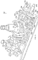
- FIG. 6 shows a main rotor gearbox 214 of a helicopter.
- the main rotor gearbox 214 includes a lower housing 300, a middle housing 302 and an upper housing 304.
- Main rotor gearbox 214 includes a first drive input and clutch 244a, a second drive input and clutch 244b, a tail rotor gear assembly 310, a tail rotor disc brake 246 and calipers 314, a tail rotor drive output 316, a generator output 318, hydraulic pump drive output (not shown), first accessory drive output (not shown), second accessory drive output (not shown), oil pump drive output (not shown), and mast housing 320.
- tail rotor output section chip detector 322 mast bearing chip detector 324, planetary chip detector (not shown), oil filter 326, oil filler cap 328, non-rotating scissor link mounting bracket 330.
- the first drive input and clutch 244a and second drive input and clutch 244b allow for single engine start and decoupling of either engine/reduction gearbox for single engine operation.
- the main gear box 214 minimizes the number of single path drive system components and provides maximum system separation and redundancy.
- Non-limiting examples of composite materials for use with the drive shafts include, e.g., metals, carbon fiber, metal-carbon fiber, fiber reinforcement unidirectional layers embedded in the thermoplastic polymer, or combinations thereof.
- the composite drive shafts may be a composite tube that is a braided fiber and resin transfer molded component. Such components are typically more damage tolerant and have a higher ballistic survivability.
- the braided fiber may be either a two-dimensional or a three-dimensional braided fiber.
- the composite shaft may also be manufactured by filament winding, fiber placement, or any other processes that are deemed appropriate.
- the drive shafts can also include end adapters, which can be formed from a metallic material, such as aluminum, titanium, or steel, but may be formed from any other suitable rigid material, including non-metallic material.
- end adapters can be formed from a metallic material, such as aluminum, titanium, or steel, but may be formed from any other suitable rigid material, including non-metallic material.
- Composite materials and manufacturing of composite drive shafts are taught in, e.g., U.S. Patent No. 7,335,108 .
Landscapes
- Engineering & Computer Science (AREA)
- Mechanical Engineering (AREA)
- General Engineering & Computer Science (AREA)
- Aviation & Aerospace Engineering (AREA)
- Transportation (AREA)
- General Details Of Gearings (AREA)
Description
- This patent application claims priority to
U.S. provisional patent application serial number 62/399,097 filed on September 23, 2016 U.S. provisional patent application serial number 62/423,371 filed on November 17, 2016 - The present invention relates to an aircraft drive system, a method of providing redundant power to a main rotor gearbox, and a helicopter.
- Without limiting the scope of the invention, its background is described in connection with rotorcraft drive systems.
- Since their inception, rotorcraft and rotorcraft drive systems have been improved to reduce the possibility of failure during flight. Toward that end, a number of modifications have been made to drive systems to improve reliability. However, despite advances in materials and design, a number of failures continue to occur that affect rotorcraft performance. One example of a problem with current rotorcraft drive systems is that, in some instances, the failure of single drive system component leads to failure of the entire drive system. Another example is a loss of lubrication event that causes the loss of torque transmission by drive system subcomponents such as gearboxes or accessories connected to the main rotor gearbox.
- More particularly, the failure of a single gearbox or shaft connected to the main rotor gearbox can significantly impact operations. For example, if there is a loss of lubrication to a gearbox, the gearbox loses torque transmission, causing damage to upstream or downstream components. The same can occur when a shaft becomes unbalanced (or breaks), which can damage couplings, gearboxes and even the main rotor gearbox. Unfortunately, when a portion of a drive system experiences a failure or reduction in performance, the concomitant reduction in power leads to challenges with flight performance.
- Thus, a need remains for improving the overall safety and reliability of rotorcraft drive systems that include the connections between the engines and the main rotor gearbox, reduction and accessory gearboxes, shafts, generators, oil pumps, and accessories connected to the main rotor gearbox. Specifically, systems and methods that minimize the number of single load path components, provide maximum system separation and redundancy, minimize maintenance required and maintenance related incidents, minimize the potential of loss of lubrication events, and maximize main rotor gearbox loss of lubrication capability are desirable, including systems and methods for cooling components and systems during normal operations and during loss of lubrication events.
- "Sikorsky Archives | S-65/H-53A/D Sea Stallion/ H-53E Super Stallion", as retrieved from https://www.sikorskyarchives.com/S-65H-53D%20SEA%20STALLION.php on 24 May 2019, discloses two transmission systems each comprising a main gearbox and an accessory gearbox.
- "Helicopter Drive System On-Condition Maintenance Capability", published by Sikorsky Aircraft Division of United Technologies Corporation in July 1976, discloses a transmission system comprising a main gearbox and an accessory gearbox.
-
US2006266883 discloses a gearbox of a high speed compound rotary-wing aircraft including a main module, an input module and a translational thrust module. The input module receives power from the engines to drive a dual, contra-rotating, coaxial main rotor system and a translational thrust system which provides significant translational thrust generally parallel to an aircraft longitudinal axis. Each of a multiple of engine drives the input module such that power is distributed to the main module and the translational thrust module. -
EP2412995 discloses a drive train with a rolling bearing for a shaft, a fixed outer ring, an inner ring rotating relative to said outer ring and at least one intermediate socket mounted on the shaft inside the inner ring. At least one shell is provided between the socket and the inner ring, said shell being provided with a cylindrical outer area of contact to an inner circumferential surface of the inner ring and with at least one lateral extension beyond the area of contact with the inner ring. -
US6302356 discloses a twin turbine engine helicopter having a two-stage main reduction gearbox, the input stage having a speed reduction ratio exceeding 5.5:1, into an epicyclic gear train second stage ratio about 6:1 for approximately 30:1 or higher overall ratio output to the main rotor. In various embodiments, the first stage uses face gears, or bevel gears, with a reduction greater than 5.5:1 and a second stage epicyclic gear train using single or double row helical or spur gears. The first stage gears are straddle mounted in the housing. - An aspects of the invention is set out according to appended claim 1. Embodiments of the invention are set out according to the appended dependent claims. The first and second engine reduction gearboxes may comprise a plurality of gears that reduce a shaft speed from the first and second engines from a high speed at or near turbine engine speed of greater than 10,000 revolutions per minute at an input of the first and second engine reduction gearboxes, respectively, to a speed substantially lower than the high speed, a low speed of less than about 6,000 revolutions per minute at an output of the first and second engine reduction gearboxes. An output shaft may comprise a tail rotor disc brake and calipers for slowing or stopping the drive system. The main rotor gearbox may comprise a low speed overhung planetary gear system. The drive system may further comprise a drive shaft assembly connected to an output of the main rotor gearbox, wherein the drive shaft assembly comprises one or more drive shafts, each of the drive shafts connected to one or more bearing assemblies, the drive shaft assembly having a proximal and a distal end, and an intermediate gear box connected to the distal end of the one or more drive shafts, wherein the intermediate gear box is connected to a tail rotor gearbox via a tail rotor drive shaft. The drive system may further comprise at least one of: one or more cooling fans, or one or more oil pumps, one or more hydraulic power packs, or one or more generators, each connected directly or indirectly to the main rotor gearbox independently. The drive system may further comprise an oil cooler mounted directly to the main rotor gearbox. The drive system may further comprise two or more hydraulic power packs wherein each of the two or more hydraulic power packs is independent from and redundant with the other hydraulic power packs. The drive system may further comprise two or more oil cooler blowers wherein each of the two or more oil cooler blowers is independent from and redundant with the other oil cooler blowers. The drive system may further comprise two or more generators wherein each of the two or more generators is independent from and redundant with the other generators.
- Another aspect of the invention is set out according to appended claim 2. Embodiments of the invention are set out according to the appended dependent claims. The first and second engine reduction gearboxes may comprise a plurality of gears that reduce a shaft speed from the first and second engines from up to a high speed at or near turbine engine speed of greater than 10,000 revolutions per minute at an input of the first and second engine reduction gearboxes, respectively, to a speed substantially lower than the high speed, a low speed of less than about 6,000 revolutions per minute at an output of the first and second engine reduction gearboxes. The method may further comprise connecting a drive shaft with flexible couplings between each of the first and second engine reduction gearboxes and the first and second inputs of the main rotor gearbox, respectively. An output shaft may comprise a tail rotor disc brake and calipers for slowing or stopping the drive system. The main rotor gearbox may comprise a low speed overhung planetary gear system. The method may further comprise connecting a drive shaft assembly to an output of the main rotor gearbox, wherein the drive shaft assembly comprises one or more drive shafts, each of the drive shafts connected to one or more bearing assemblies, the drive shaft assembly having a proximal and a distal end, and an intermediate gear box connected to the distal end of the one or more drive shafts, wherein the intermediate gear box is connected to a tail rotor gearbox via a tail rotor drive shaft. The method may further comprise providing at least one of: one or more cooling fans, or one or more oil pumps, one or more hydraulic power packs, or one or more generators, each connected directly or indirectly to the main rotor gearbox independently. The method may further comprise mounting an oil cooler directly to the main rotor gearbox. The method may further comprise mounting two or more hydraulic power packs wherein each of the two or more hydraulic power packs is independent from and redundant with the other hydraulic power packs. The method may further comprise mounting two or more oil cooler blowers wherein each of the two or more oil cooler blowers is independent from and redundant with the other oil cooler blowers. The method may further comprise mounting two or more generators wherein each of the two or more generators is independent from and redundant with the other generators.
- For a more complete understanding of the features and advantages of the present invention, reference is now made to the detailed description of the invention along with the accompanying figures and in which:
-
FIG. 1 shows a side view of a helicopter according to a preferred embodiment of the present application; -
FIG. 2 shows a partial cross-section, perspective view of helicopter aircraft according to an alternative embodiment of the present application; -
FIG. 3 shows an isometric view of a drive system not falling within the scope of the present invention. -
FIG. 4 shows a close-up, isometric view of a fan assembly for use with the drive system of the present invention. -
FIG. 5 shows an isometric view of another portion of the drive system that provides system separation and redundancy. -
FIG. 6 shows a main rotor gearbox of a helicopter according to an embodiment of the present application - The present invention addresses the problems with drive systems in use today that are known to lead to rotorcraft failure. More particularly, the drive system of the present invention was designed to overcome drive system failures by including one or more of the following design features: (1) minimize the number of single path drive system components; (2) provide maximum system separation and redundancy; (3) minimize maintenance requirements and maintenance related incidents; (4) minimize the potential of loss of lubrication events; and/or (5) maximize main rotor gearbox loss of lubrication capability. The rotorcraft drive system described herein includes, e.g., dual engine reduction gearboxes completely isolated from the remainder of drive system via freewheeling clutches in the main rotor gearbox, dual accessory gearboxes separate from the main rotor gearbox, and the distribution of the gearbox driven accessories among the separate systems, among other improvements.
- The present invention was developed to address the failures common to rotorcraft drive systems and is based on a completely new design and application of new technology to rotorcraft safety. More particularly, the new rotorcraft drive system is focused in an unparalleled manner on safety and redundancy. The goal of safety drove the design and development of the unique layout and configuration of the rotorcraft drive system described herein, which incorporates unique features and system separation that protects primary aircraft systems from the most common drive system failures. The drive system has also been designed to maximize the operational capability in the event of an uncommon failure, such as a loss of lubrication.
- Moreover, the present inventors recognized that high-speed gearing and the associated heat generation is always an area of concern for gearbox survivability. The ability to continue torque transmission, particularly in a loss of lubrication scenario, is of great importance. For this reason, the drive system described herein includes two separate reduction gearboxes (RGB's), each one connected to a separate engine and independent from the Main Rotor Gearbox (MRGB). The reduction gearboxes are fully self-contained and separate from each other, each reducing the engine output speed from a high speed at or near turbine engine speed of greater than 10,000 RPM to a speed substantially lower than the high speed, a low speed of less than about 6,000 RPM, prior to transmitting torque to the MRGB. With this drive system arrangement high-speed gearing is contained in separate gearboxes, as such, the survivability of the total drive system is greatly enhanced, particularly in the event of high-speed gear failure or loss of lubricant in an individual RGB.
- According to one embodiment, the MRGB has additional unique features including the low speed (less than about 6,000 RPM) input. The use of independent RGBs that connect to a single low speed overhung planetary gear system in the MRGB reduces rotating part count and heat generation. Low gear count is achieved by the use of compound gears that incorporate compartmentalized lubrication recovery elements and one or more independent and monitored chip detectors. With maintenance in mind, the drive system allows for a short mast top case assembly that allows swapping of the top case and mast without removal of the main rotor gearbox from the aircraft. The MRGB also includes a clutch for each input of the reduction gearboxes that allows each reduction gearbox to be separately and independently disconnected from the MRGB.
- High-speed gearing and the associated heat generation is always an area of concern for gearbox survivability. The ability to continue torque transmission, particularly in a loss of lubrication scenario is of great importance. For this reason, the present invention includes a powertrain for a rotorcraft that includes two separate engine reduction gearboxes (RGB), e.g., one RGB for each engine of a two-engine rotorcraft. The reduction gearboxes are fully self-contained and separate from each other, reducing the engine output speed from a high speed at or near turbine engine speed of greater than 10,000 RPM to a speed substantially lower than the high speed, e.g., a low speed of less than about 6,000 RPM, prior to transmitting torque to the main rotor gearbox (MRGB). This rotational speed reduction is accomplished with, e.g., a simple three (3)-gear reduction. The rotational reduction can be accomplished with 2, 3, 4, 5, 6 or more gears; however, a 3 gear system provided the requisite reduction. Each RGB has its own self-contained lubrication system consisting of pump, filter, oil monitoring sensors, and a unique core in the aircraft cooler assembly.
- With this arrangement, where high-speed gearing is contained in separate gearboxes, the survivability of the total drive system is greatly enhanced, particularly in the event of high speed gear failure or loss of lubricant in an individual RGB. Each reduction gearbox can be disconnected from the MRGB by a clutch.
- The Main Rotor Gearbox (MRGB) transmits torque from the Reduction Gearboxes (RGB) to the main rotor mast, the hydraulic pump and generator that is mounted to the MRGB, and to the tail rotor drive shaft.
- The drive system of the present invention can also take advantage of a number of additional features that minimize the possibility of loss of lubricant and to maximize the operational time if a loss of lubricant event does occur. For example, the drive system can also include one or more of the following: (1) the use of transfer tubes for cooler and filter mounting to eliminate the loss of lubricant in the event of loss of attachment fastener torque; (2) using an oil cooler mounted directly to the main rotor gearbox eliminating external hoses; (3) the use of all oil filter bowls are screw-on instead of held-on with small fasteners eliminating fastener failure issue from repeated removals; (4) the elimination of a high speed planetary and the heat generation associated with it during a loss of lubrication event; (5) the use of gear tooth geometry specifically designed to minimize sliding reducing heat generation at the teeth and the tendency to score during a loss of lubrication event; (6) the use of coarse pitch power gears with clearance or backlash allowing for the expansion during high heat loss of lubrication events; (7) the use of high hot hardness material utilized for primary torque carrying components maximizing their continued operation in the event of a loss of lubrication event; (8) the use of ring gear and case joint design to efficiently transmit heat away from the planetary gears in the event of a loss of lubrication event; and/or (9) the use of isotropic super finished gear teeth resulting in a greatly improved surface finish and maximizing the ability of these gears to operate in a reduced lubrication environment.
-
FIG. 1 shows ahelicopter 100 in accordance with a preferred embodiment of the present application. In the exemplary embodiment,aircraft 100 is a helicopter having afuselage 102 and arotor system 104 carried thereon. A plurality ofrotor blades 106 is operably associated with arotor system 104 for creating flight. Atail boom 108 is depicted that further includestail rotor 110. - For example,
FIG. 2 shows a partial cross-section perspective view ofhelicopter 100 that includes additional detail of an embodiment of the present invention.Helicopter 100 further includes arotor mast 112, which is connected to themain rotor gearbox 114. Themain rotor gearbox 114 is connected to one or moreaccessory gear boxes 116 and one or moreengine reduction gearboxes engine reduction gearbox more engines engine compartment 118. A tailrotor drive shaft 122 transmits mechanical rotation from themain rotor gearbox 114 to the tailrotor gear box 124, which is connected via tailrotor drive shaft 126 andintermediate gear box 128. -
FIG. 3 shows adrive system 200 that includes adrive shaft assembly 202 that includesmultiple drive shafts Drive system 200 can also include a tailrotor drive shaft 204e. The drive shafts may be made from composite material, aluminum, titanium, or the like. In one example, driveshaft 204a is an aluminum driveshaft while the remainingdrive shafts drive shaft 204a nearest the engines in order to maintain mechanical integrity in a high temperature environment, including, for instance, in the event of an engine fire. In another example,drive shafts drive shafts drive shaft assembly 202 are connected byassemblies drive shafts fan assembly 224 may be integrated into one ormore connection assemblies drive shaft 204a nearest the engines is composite, afan assembly 224 may be integrated intoconnection assembly 210a to provide air flow arounddrive shaft 204a in order to reduce the temperatures to which driveshaft 204a is normally exposed or to reduce the temperatures under abnormal conditions (e.g., in the event of an engine fire). - The
drive shaft assembly 202 is connected at a distal end to anintermediate gearbox 206, which is connected totail rotor gearbox 208 viadrive shaft 204e andflexible couplings drive shaft assembly 202 is connected to the main rotor gearbox, which is powered by twoengine reduction gearboxes main rotor gearbox 214 and thedrive shaft assembly 202. Each of theengine reduction gearboxes main rotor gearbox 214 and to thedrive shaft assembly 202 that is connected to thetail rotor gearbox 208. Each of theengine reduction gearboxes main rotor gearbox 214 via main rotorgearbox input shafts engine reduction gearboxes gearbox input shafts engine reduction gearboxes main rotor gearbox 214 via, e.g., couplings. Themain rotor gearbox 214 is also depicted as also connected toaccessory gearboxes - The skilled artisan will recognize that the
drive system 200 provides a drive system configuration that was designed to: minimize the number of single load path components, provide maximum system separation and redundancy, minimize maintenance required and maintenance related incidents, minimize the potential of loss of lube events, and maximize main rotor gearbox loss of lube capability. Thus, by providing completely independent or redundantengine reduction gearboxes engine reduction gearbox main rotor gearbox 214. As such, loss of a single reduction gearbox does not prevent continued safe flight. - More particularly, all the high-speed rotating components are separated from the main rotor gearbox, and are moved into redundant reduction gearboxes. As such, even when there is a failure in a reduction gearbox, such a failure does not impact the main rotor gearbox operation, because even if the failed reduction gearbox loses torque transmission (because of the inclusion of freewheeling clutches in the MRGB) the reduction gearbox still operating will provide sufficient power to maintain flight from the engine associated with the operational reduction gearbox to safely operate and land the aircraft. By moving the high-speed rotating components away from the main rotor gearbox, the time and expense of maintenance to replace a reduction gearbox is greatly reduced as it is no longer necessary to disassemble the main rotor gearbox to replace components during scheduled maintenance or the result of a reduction gearbox failure.
- Several key elements of the
drive system 200 include the separation of dual engine reduction gearboxes, which are completely isolated from remainder of drive system via freewheeling clutches in the main rotor gearbox. Further, thedrive system 200 provides dual accessory gearboxes separate from the main rotor gearbox. In addition, the distribution of the gearbox driven accessories is among the separate systems, thereby providing full redundant systems. Due to the use of redundant and separate power pathways, the failure of some accessories that would otherwise be critical (e.g., loss of hydraulic pumps, cooling blowers, generators, etc.), is overcome by the separate power pathway. Thus, if one accessory gearbox fails, or if one of the accessories associated with an accessory gearbox fails, the remaining redundant accessory gearbox and its associated accessories are designed to provide for safely operating and landing of the aircraft. - The present invention utilises non-pressurized accessory gearboxes. The accessory gearboxes include the gears that connect to an output from the engines. The gearboxes will generally include one or more of the following: an oil level gauge, an oil level sensor, an oil filler cap, and/or a sump chip detector. The housing for the accessory gearboxes can also include provisions for certain outputs, such as: a permanent magnet generator that generates an electrical output, a blower, a generator, or a hydraulic pump. The gears within the accessory gearboxes are sized to provide the necessary speeds and torques required by each gearbox output. Typically, in non-pressurized gearboxes the internal parts of the gearbox are splash lubricated.
- In embodiments, the accessory gearboxes have a lubrication system that is independent of the main rotor gearbox's lubrication system. This can decrease the frequency of loss-of-lube events by eliminating leak paths. Specifically, by providing independent lubrication systems for each of the accessory gearboxes, one can eliminate transfer tubes, hoses, and the like that would otherwise be necessary to provide circulation of lubricant between the main rotor gearbox and each of the accessory gearbox. Thus, in embodiments, each of the accessory gearboxes has a non-pressurized lubrication system that is independent of the main rotor gearbox's lubrication system.
-
FIG. 4 shows a close-up, isometric view of afan assembly 224 that is part of thedrive system 200. Driveshaft 204a, which is nearest the engines, may be a composite or a metal shaft. Thefan assembly 224 includes afan 226 that may be integrated intoconnection assembly 210a and provides air flow over and around driveshaft 204a in order to reduce the temperatures to which driveshaft 204a is exposed (e.g., in the event of an engine fire). Thedrive shaft 204a is depicted within anopening 228 and surrounded byinsulation 230, which also protects thedrive shaft 204a from heat generated by the engine(s) (not depicted). Theconnection assembly 210a is depicted with aflexible coupling 232 and ahanger bearing assembly 234. -
FIG. 5 shows an isometric view of adrive system 200 that provides maximum system separation and redundancy.Drive system 200 include twoengine reduction gearboxes engine connection shaft engine reduction gearboxes engine reduction gearboxes engine reduction gearboxes separate shaft main rotor gearbox 214. Thus, each of theengine connection shafts main rotor gearbox 214, each of which operates independently and redundantly to provide shaft power to themain rotor gearbox 214. Further, each of theengine reduction gearboxes main rotor gearbox 214. Thus, themain rotor gearbox 214 can be designed to operate more reliably, with components that are turning at a much lower speed. Thedrive system 200 also connects to the tail rotor via a tail rotor shaft 204. Each of theengine connection shafts engine reduction gearboxes main rotor gearbox 214. Each of theshafts clutches main rotor gearbox 214, however, the skilled artisan will recognize that thefreewheeling clutches engine reduction gearboxes engine reduction gearboxes main rotor gearbox 214, or combinations of the same. Further, theshafts engine reduction gearboxes main rotor gearbox 214 can include flexible couplings to allow for pylon movement and can be separately uncoupled. For example, clutches can be connected to theshafts main rotor gearbox 214. In the example ofFIG. 4 , theseshafts main rotor gearbox 214 at a freewheeling clutch 244a, 244b that allows the engines andreduction gearboxes engine reduction gearboxes main rotor gearbox 214 to continue operating at speed, receiving torque from the engine and engine reduction gearbox that remains operable. Further, each freewheeling unit allows for the individual start-up and shutdown of either engine. Theshafts shafts Drive system 200 also includes a tailrotor disc brake 246 and calipers (not shown) for slowing or stoppingdrive system 200. -
FIG. 6 shows amain rotor gearbox 214 of a helicopter. Themain rotor gearbox 214 includes alower housing 300, amiddle housing 302 and anupper housing 304.Main rotor gearbox 214 includes a first drive input and clutch 244a, a second drive input and clutch 244b, a tailrotor gear assembly 310, a tailrotor disc brake 246 andcalipers 314, a tailrotor drive output 316, agenerator output 318, hydraulic pump drive output (not shown), first accessory drive output (not shown), second accessory drive output (not shown), oil pump drive output (not shown), andmast housing 320. Other features include tail rotor outputsection chip detector 322, mastbearing chip detector 324, planetary chip detector (not shown),oil filter 326,oil filler cap 328, non-rotating scissorlink mounting bracket 330. The first drive input and clutch 244a and second drive input and clutch 244b allow for single engine start and decoupling of either engine/reduction gearbox for single engine operation. Thus, themain gear box 214 minimizes the number of single path drive system components and provides maximum system separation and redundancy. - Non-limiting examples of composite materials for use with the drive shafts include, e.g., metals, carbon fiber, metal-carbon fiber, fiber reinforcement unidirectional layers embedded in the thermoplastic polymer, or combinations thereof. For example, the composite drive shafts may be a composite tube that is a braided fiber and resin transfer molded component. Such components are typically more damage tolerant and have a higher ballistic survivability. The braided fiber may be either a two-dimensional or a three-dimensional braided fiber. However, it should be understood that the composite shaft may also be manufactured by filament winding, fiber placement, or any other processes that are deemed appropriate. The drive shafts can also include end adapters, which can be formed from a metallic material, such as aluminum, titanium, or steel, but may be formed from any other suitable rigid material, including non-metallic material. Composite materials and manufacturing of composite drive shafts are taught in, e.g.,
U.S. Patent No. 7,335,108 .
Claims (13)
- An aircraft drive system (200) comprising:a first engine (120a) and a second engine (120b) a main rotor gearbox (114, 214) comprising a first drive input and a second drive input;a first drive system comprising a first engine reduction gearbox (216a) connecting the first engine (120a) to the first drive input of the main rotor gearbox (114, 214) at a reduced shaft speed;a second drive system independent from and redundant with the first drive system, the second drive system comprising a second engine reduction gearbox (216b) connecting the second engine (120b) to the second drive input of the main rotor gearbox (114, 214) at the reduced shaft speed; and two or more accessory gearboxes (116, 222a, 222b) connecting an output of the first engine (120a) or the second engine (120b) with one or more accessories; whereina first accessory gearbox (116, 222a) of the two or more accessory gearboxes (116, 222a, 222b) connecting an output of the first engine (120a) or the second engine (120b) with one or more accessories, the first accessory gearbox (116, 222a) having a non-pressurized lubrication system independent from a lubrication system associated with the main rotor gearbox (114, 214); anda second accessory gearbox (116, 222b) of the two or more accessory gearboxes (116, 222a, 222b) connecting an output of the the first engine (120a) or the second engine (120b) with one or more accessories, the second accessory gearbox (116, 222b) having a non-pressurized lubrication system independent from a lubrication system associated with the main rotor gearbox (114, 214) and from the non-pressurized lubrication system associated with the first accessory gearbox (116, 222a);wherein the second accessory gearbox (116, 222b) is independent from and redundant with the first accessory gearbox.
- A method of providing redundant power to a main rotor gearbox (114, 214) comprising:providing the main rotor gearbox (114, 214) comprising a first drive input and a second drive input;connecting a first drive system comprising a first engine reduction gearbox (216a) for connecting a first engine (120a) to the first drive input of the main rotor gearbox (114, 214) at a reduced shaft speed;connecting a second drive system independent from and redundant with the first drive system, the second drive system comprising a second engine reduction gearbox (216b) for connecting a second engine (120b) to the second drive input of the main rotor gearbox (114, 214) at the reduced shaft speed; andproviding two or more accessory gearboxes (116, 222a, 222b);connecting the two or more accessory gearboxes (116, 222a, 222b) directly to the first engine (120a) or the second engine (120b);mounting a first accessory gearbox (116, 222a) of the two or more accessory gearboxes (116, 222a, 222b) connecting an output of the first engine (120a) or the second engine (120b) with one or more accessories, the first accessory gearbox (116, 222a) having a non-pressurized lubrication system independent from a lubrication system associated with the main rotor gearbox (114, 214); andmounting a second accessory gearbox (116, 222b) of the two or more accessory gearboxes (116, 222a, 222b) connecting an output of the first engine (120a) or the second engine (120b) with one or more accessories, the second accessory gearbox (116, 222b) having a non-pressurized lubrication system independent from a lubrication system associated with the main rotor gearbox (114, 214);wherein the second accessory gearbox (116, 222b) is independent from and redundant with the first accessory gearbox.
- The drive system of claim 1 or the method of claim 2, further comprising a drive shaft (242a, 242b) connecting each of the first and second engine reduction gearboxes (216a, 216b) to the first and second drive inputs of the main rotor gearbox (114, 214), respectively.
- The drive system or method of claim 3, wherein the drive shafts (242a, 242b) connect to the first and second engine reduction gearboxes (216a, 216b) or the first and second drive inputs of the main rotor gearbox (114, 214) via freewheeling clutches (244a, 244b).
- The drive system or method of claim 3, wherein the drive shafts (242a, 242b) have flexible couplings.
- The drive system of claim 1 or any preceding system claim, or the method of claim 2 or any preceding method claim, wherein each of the first and second engine reduction gearboxes (216a, 216b) is independently lubricated and cooled.
- The drive system of claim 1 or of any preceding system claim, or the method of claim 2 or of any preceding method claim, wherein each of the first and second engine reduction gearboxes (216a, 216b) are configured to be independently decoupled from the main rotor gearbox (114, 214).
- The drive system of claim 1 or of any preceding system claim, further comprising a tail rotor gear assembly (310) connected to the main rotor gearbox (114, 214), a tail rotor drive output (316) connected to the tail rotor gear assembly (310) via a tail rotor disc brake (246) and calipers (314), a tail rotor drive shaft (122) connected to the tail rotor drive output (316), and a tail rotor gearbox (124) connected to the tail rotor drive shaft (122) via a tail rotor drive shaft (126, 204e) and an intermediate gearbox (128); or
the method of claim 2 or of any preceding method claim, further comprising connecting a tail rotor gear assembly (310) to the main rotor gearbox (114, 214), connecting a tail rotor drive output (316) to the tail rotor gear assembly (310) via a tail rotor disc brake (246) and calipers (314), connecting a tail rotor drive shaft (122) to the tail rotor drive output (316), and connecting a tail rotor gearbox (124) to the tail rotor drive shaft (122) via a tail rotor drive shaft (126, 204e) and an intermediate gearbox (128). - The drive system or method of claim 8, wherein the tail rotor drive shaft (122) comprises a drive shaft assembly (202) having two or more drive shafts (204a, 204b, 204c, 204d) connected to one another via one or more connection assemblies (210a, 210b, 210c).
- The drive system or method of claim 9, wherein a fan assembly (224) is integrated into one or more of the connection assemblies (210a, 210b, 210c).
- The drive system or method of claim 9, wherein the one or more connection assemblies (210a, 210b, 210c) comprise flexible couplings and hanger bearing assemblies.
- The drive system of claim 1 or of any preceding system claim, orthe method of claim 2 or of any preceding method claim, further comprising the one or more accessories, and whereinthe one or more accessories connected to the first accessory gearbox (116, 222a) are independent from and redundant with the one or more accessories connected to the second accessory gearbox (116, 222b).
- A helicopter (100), comprising:a fuselage (102);a drive system (200) according to claim 1 or of any preceding system claim, wherein the drive system (200) is coupled to the fuselage (102); anda rotor system (104) connected to the main rotor gearbox (114, 214) to provide flight.
Applications Claiming Priority (4)
| Application Number | Priority Date | Filing Date | Title |
|---|---|---|---|
| US201662399097P | 2016-09-23 | 2016-09-23 | |
| US201662423371P | 2016-11-17 | 2016-11-17 | |
| US15/702,912 US20180086444A1 (en) | 2016-09-23 | 2017-09-13 | Aircraft Drive System |
| EP17192698.3A EP3299286B1 (en) | 2016-09-23 | 2017-09-22 | Aircraft drive system |
Related Parent Applications (1)
| Application Number | Title | Priority Date | Filing Date |
|---|---|---|---|
| EP17192698.3A Division EP3299286B1 (en) | 2016-09-23 | 2017-09-22 | Aircraft drive system |
Publications (2)
| Publication Number | Publication Date |
|---|---|
| EP3712063A1 EP3712063A1 (en) | 2020-09-23 |
| EP3712063B1 true EP3712063B1 (en) | 2022-07-27 |
Family
ID=59955471
Family Applications (2)
| Application Number | Title | Priority Date | Filing Date |
|---|---|---|---|
| EP17192698.3A Active EP3299286B1 (en) | 2016-09-23 | 2017-09-22 | Aircraft drive system |
| EP20169878.4A Active EP3712063B1 (en) | 2016-09-23 | 2017-09-22 | Aircraft drive system |
Family Applications Before (1)
| Application Number | Title | Priority Date | Filing Date |
|---|---|---|---|
| EP17192698.3A Active EP3299286B1 (en) | 2016-09-23 | 2017-09-22 | Aircraft drive system |
Country Status (2)
| Country | Link |
|---|---|
| US (1) | US20180086444A1 (en) |
| EP (2) | EP3299286B1 (en) |
Families Citing this family (13)
| Publication number | Priority date | Publication date | Assignee | Title |
|---|---|---|---|---|
| US10677343B2 (en) * | 2015-02-18 | 2020-06-09 | Sikorsky Aircraft Corporation | Fluid distribution assembly having anti-clog inlet housing |
| US11313455B2 (en) | 2018-10-05 | 2022-04-26 | Textron Innovations Inc. | Aircraft gearbox lubrication system with multiple lubrication subsystems |
| US10793284B2 (en) * | 2019-02-05 | 2020-10-06 | Bell Textron Inc. | Multimode clutch assemblies for rotorcraft |
| US11174013B2 (en) | 2019-02-05 | 2021-11-16 | Textron Innovations Inc. | Failsafe multimode clutch assemblies for rotorcraft |
| US12049304B2 (en) | 2019-02-05 | 2024-07-30 | Textron Innovations Inc. | Tail rotor isolation systems for rotorcraft |
| US11174014B2 (en) | 2019-02-05 | 2021-11-16 | Textron Innovations Inc. | Failsafe multimode clutch assemblies for rotorcraft |
| US10788088B2 (en) * | 2019-02-05 | 2020-09-29 | Bell Textron Inc. | Multimode powertrains for rotorcraft |
| US11174015B2 (en) | 2019-02-05 | 2021-11-16 | Textron Innovations Inc. | Multimode clutch assemblies having engagement status sensors |
| US11708868B2 (en) | 2019-02-13 | 2023-07-25 | Textron Innovations Inc. | Failsafe multimode clutch assemblies for rotorcraft |
| FR3107745B1 (en) * | 2020-02-27 | 2022-07-01 | Arquus | Motion transmission member intended to be mounted on a motor vehicle and motor vehicle comprising such a motion transmission member |
| US11760470B2 (en) | 2021-03-20 | 2023-09-19 | Textron Innovations Inc. | Rotorcraft lockout during transport |
| US12209620B2 (en) * | 2022-01-12 | 2025-01-28 | Goodrich Corporation | Flexible coupling for joining metallic and composite drive shafts |
| WO2023135275A1 (en) * | 2022-01-14 | 2023-07-20 | Roze Mobility | Hybrid-use rotary-wing aircraft with aligned drivetrain |
Family Cites Families (9)
| Publication number | Priority date | Publication date | Assignee | Title |
|---|---|---|---|---|
| EP0091744A1 (en) * | 1982-04-08 | 1983-10-19 | WESTLAND plc | Helicopter transmission systems |
| JP3029981B2 (en) * | 1995-04-27 | 2000-04-10 | 株式会社コミュータヘリコプタ先進技術研究所 | Helicopter power transmission |
| US6302356B1 (en) * | 1998-08-21 | 2001-10-16 | Rolls-Royce Corporation | Helicopter two stage main reduction gearbox |
| CA2481730C (en) | 2002-04-19 | 2010-03-23 | Bell Helicopter Textron Inc. | Composite drive shaft with captured end adapters |
| US20050151001A1 (en) * | 2003-07-02 | 2005-07-14 | Loper Arthur W. | Compound helicopter |
| US7118328B2 (en) * | 2004-03-12 | 2006-10-10 | Sikorsky Aircraft Corporation | Gearbox mounted force generator |
| US7413142B2 (en) * | 2005-05-31 | 2008-08-19 | Sikorsky Aircraft Corporation | Split torque gearbox for rotary wing aircraft with translational thrust system |
| EP2412995B1 (en) * | 2010-07-30 | 2012-12-12 | Eurocopter Deutschland GmbH | Drive train |
| EP3194791B1 (en) * | 2014-07-31 | 2020-01-08 | Sikorsky Aircraft Corporation | Gearbox oil cooling assembly |
-
2017
- 2017-09-13 US US15/702,912 patent/US20180086444A1/en not_active Abandoned
- 2017-09-22 EP EP17192698.3A patent/EP3299286B1/en active Active
- 2017-09-22 EP EP20169878.4A patent/EP3712063B1/en active Active
Also Published As
| Publication number | Publication date |
|---|---|
| US20180086444A1 (en) | 2018-03-29 |
| EP3299286A1 (en) | 2018-03-28 |
| EP3712063A1 (en) | 2020-09-23 |
| EP3299286B1 (en) | 2020-04-29 |
Similar Documents
| Publication | Publication Date | Title |
|---|---|---|
| EP3712063B1 (en) | Aircraft drive system | |
| EP3299283B1 (en) | Non-pressurized accessory gearbox | |
| EP3002433B1 (en) | Geared architecture for a gas turbine | |
| EP3299674B1 (en) | Oil-level sensor for a gearbox | |
| US20080053257A1 (en) | Device for driving the rotor of turbine engine auxiliary | |
| US10385959B2 (en) | Flange-mounted ring gear for improved heat management | |
| EP3567282A1 (en) | Use of metering hole in shroud of splash-lubricated gearbox for disbursing lubricant within gearbox | |
| EP3299289B1 (en) | Redundant cooling system | |
| US11454312B2 (en) | Redundant fans for cooling system | |
| US11999503B2 (en) | Articulating bifurcated integrated transition duct assembly | |
| EP3299673B1 (en) | Fan mounted on gearshaft | |
| EP3299676B1 (en) | Flange-mounted ring gear for improved heat management | |
| EP3299288B1 (en) | High speed engine reduction gearboxes | |
| US10830333B2 (en) | Gearbox filler assembly | |
| EP3564558A1 (en) | Bypass block for unregulated gearboxes | |
| US20250122841A1 (en) | Lubrication system for aircraft powerplant and clutch system |
Legal Events
| Date | Code | Title | Description |
|---|---|---|---|
| STAA | Information on the status of an ep patent application or granted ep patent |
Free format text: STATUS: EXAMINATION IS IN PROGRESS |
|
| PUAI | Public reference made under article 153(3) epc to a published international application that has entered the european phase |
Free format text: ORIGINAL CODE: 0009012 |
|
| 17P | Request for examination filed |
Effective date: 20200416 |
|
| AC | Divisional application: reference to earlier application |
Ref document number: 3299286 Country of ref document: EP Kind code of ref document: P |
|
| AK | Designated contracting states |
Kind code of ref document: A1 Designated state(s): AL AT BE BG CH CY CZ DE DK EE ES FI FR GB GR HR HU IE IS IT LI LT LU LV MC MK MT NL NO PL PT RO RS SE SI SK SM TR |
|
| GRAP | Despatch of communication of intention to grant a patent |
Free format text: ORIGINAL CODE: EPIDOSNIGR1 |
|
| STAA | Information on the status of an ep patent application or granted ep patent |
Free format text: STATUS: GRANT OF PATENT IS INTENDED |
|
| INTG | Intention to grant announced |
Effective date: 20220118 |
|
| GRAJ | Information related to disapproval of communication of intention to grant by the applicant or resumption of examination proceedings by the epo deleted |
Free format text: ORIGINAL CODE: EPIDOSDIGR1 |
|
| STAA | Information on the status of an ep patent application or granted ep patent |
Free format text: STATUS: EXAMINATION IS IN PROGRESS |
|
| GRAP | Despatch of communication of intention to grant a patent |
Free format text: ORIGINAL CODE: EPIDOSNIGR1 |
|
| STAA | Information on the status of an ep patent application or granted ep patent |
Free format text: STATUS: GRANT OF PATENT IS INTENDED |
|
| INTC | Intention to grant announced (deleted) | ||
| RAP1 | Party data changed (applicant data changed or rights of an application transferred) |
Owner name: TEXTRON INNOVATIONS INC. |
|
| GRAS | Grant fee paid |
Free format text: ORIGINAL CODE: EPIDOSNIGR3 |
|
| INTG | Intention to grant announced |
Effective date: 20220530 |
|
| GRAA | (expected) grant |
Free format text: ORIGINAL CODE: 0009210 |
|
| STAA | Information on the status of an ep patent application or granted ep patent |
Free format text: STATUS: THE PATENT HAS BEEN GRANTED |
|
| AC | Divisional application: reference to earlier application |
Ref document number: 3299286 Country of ref document: EP Kind code of ref document: P |
|
| AK | Designated contracting states |
Kind code of ref document: B1 Designated state(s): AL AT BE BG CH CY CZ DE DK EE ES FI FR GB GR HR HU IE IS IT LI LT LU LV MC MK MT NL NO PL PT RO RS SE SI SK SM TR |
|
| REG | Reference to a national code |
Ref country code: CH Ref legal event code: EP |
|
| REG | Reference to a national code |
Ref country code: AT Ref legal event code: REF Ref document number: 1506913 Country of ref document: AT Kind code of ref document: T Effective date: 20220815 |
|
| REG | Reference to a national code |
Ref country code: DE Ref legal event code: R096 Ref document number: 602017060069 Country of ref document: DE |
|
| REG | Reference to a national code |
Ref country code: IE Ref legal event code: FG4D |
|
| REG | Reference to a national code |
Ref country code: LT Ref legal event code: MG9D |
|
| REG | Reference to a national code |
Ref country code: NL Ref legal event code: MP Effective date: 20220727 |
|
| PG25 | Lapsed in a contracting state [announced via postgrant information from national office to epo] |
Ref country code: SE Free format text: LAPSE BECAUSE OF FAILURE TO SUBMIT A TRANSLATION OF THE DESCRIPTION OR TO PAY THE FEE WITHIN THE PRESCRIBED TIME-LIMIT Effective date: 20220727 Ref country code: RS Free format text: LAPSE BECAUSE OF FAILURE TO SUBMIT A TRANSLATION OF THE DESCRIPTION OR TO PAY THE FEE WITHIN THE PRESCRIBED TIME-LIMIT Effective date: 20220727 Ref country code: PT Free format text: LAPSE BECAUSE OF FAILURE TO SUBMIT A TRANSLATION OF THE DESCRIPTION OR TO PAY THE FEE WITHIN THE PRESCRIBED TIME-LIMIT Effective date: 20221128 Ref country code: NO Free format text: LAPSE BECAUSE OF FAILURE TO SUBMIT A TRANSLATION OF THE DESCRIPTION OR TO PAY THE FEE WITHIN THE PRESCRIBED TIME-LIMIT Effective date: 20221027 Ref country code: NL Free format text: LAPSE BECAUSE OF FAILURE TO SUBMIT A TRANSLATION OF THE DESCRIPTION OR TO PAY THE FEE WITHIN THE PRESCRIBED TIME-LIMIT Effective date: 20220727 Ref country code: LV Free format text: LAPSE BECAUSE OF FAILURE TO SUBMIT A TRANSLATION OF THE DESCRIPTION OR TO PAY THE FEE WITHIN THE PRESCRIBED TIME-LIMIT Effective date: 20220727 Ref country code: LT Free format text: LAPSE BECAUSE OF FAILURE TO SUBMIT A TRANSLATION OF THE DESCRIPTION OR TO PAY THE FEE WITHIN THE PRESCRIBED TIME-LIMIT Effective date: 20220727 Ref country code: FI Free format text: LAPSE BECAUSE OF FAILURE TO SUBMIT A TRANSLATION OF THE DESCRIPTION OR TO PAY THE FEE WITHIN THE PRESCRIBED TIME-LIMIT Effective date: 20220727 Ref country code: ES Free format text: LAPSE BECAUSE OF FAILURE TO SUBMIT A TRANSLATION OF THE DESCRIPTION OR TO PAY THE FEE WITHIN THE PRESCRIBED TIME-LIMIT Effective date: 20220727 |
|
| REG | Reference to a national code |
Ref country code: AT Ref legal event code: MK05 Ref document number: 1506913 Country of ref document: AT Kind code of ref document: T Effective date: 20220727 |
|
| PG25 | Lapsed in a contracting state [announced via postgrant information from national office to epo] |
Ref country code: PL Free format text: LAPSE BECAUSE OF FAILURE TO SUBMIT A TRANSLATION OF THE DESCRIPTION OR TO PAY THE FEE WITHIN THE PRESCRIBED TIME-LIMIT Effective date: 20220727 Ref country code: IS Free format text: LAPSE BECAUSE OF FAILURE TO SUBMIT A TRANSLATION OF THE DESCRIPTION OR TO PAY THE FEE WITHIN THE PRESCRIBED TIME-LIMIT Effective date: 20221127 Ref country code: HR Free format text: LAPSE BECAUSE OF FAILURE TO SUBMIT A TRANSLATION OF THE DESCRIPTION OR TO PAY THE FEE WITHIN THE PRESCRIBED TIME-LIMIT Effective date: 20220727 Ref country code: GR Free format text: LAPSE BECAUSE OF FAILURE TO SUBMIT A TRANSLATION OF THE DESCRIPTION OR TO PAY THE FEE WITHIN THE PRESCRIBED TIME-LIMIT Effective date: 20221028 |
|
| PG25 | Lapsed in a contracting state [announced via postgrant information from national office to epo] |
Ref country code: SM Free format text: LAPSE BECAUSE OF FAILURE TO SUBMIT A TRANSLATION OF THE DESCRIPTION OR TO PAY THE FEE WITHIN THE PRESCRIBED TIME-LIMIT Effective date: 20220727 Ref country code: RO Free format text: LAPSE BECAUSE OF FAILURE TO SUBMIT A TRANSLATION OF THE DESCRIPTION OR TO PAY THE FEE WITHIN THE PRESCRIBED TIME-LIMIT Effective date: 20220727 Ref country code: MC Free format text: LAPSE BECAUSE OF FAILURE TO SUBMIT A TRANSLATION OF THE DESCRIPTION OR TO PAY THE FEE WITHIN THE PRESCRIBED TIME-LIMIT Effective date: 20220727 Ref country code: DK Free format text: LAPSE BECAUSE OF FAILURE TO SUBMIT A TRANSLATION OF THE DESCRIPTION OR TO PAY THE FEE WITHIN THE PRESCRIBED TIME-LIMIT Effective date: 20220727 Ref country code: CZ Free format text: LAPSE BECAUSE OF FAILURE TO SUBMIT A TRANSLATION OF THE DESCRIPTION OR TO PAY THE FEE WITHIN THE PRESCRIBED TIME-LIMIT Effective date: 20220727 Ref country code: AT Free format text: LAPSE BECAUSE OF FAILURE TO SUBMIT A TRANSLATION OF THE DESCRIPTION OR TO PAY THE FEE WITHIN THE PRESCRIBED TIME-LIMIT Effective date: 20220727 |
|
| REG | Reference to a national code |
Ref country code: CH Ref legal event code: PL |
|
| REG | Reference to a national code |
Ref country code: DE Ref legal event code: R097 Ref document number: 602017060069 Country of ref document: DE |
|
| REG | Reference to a national code |
Ref country code: BE Ref legal event code: MM Effective date: 20220930 |
|
| PG25 | Lapsed in a contracting state [announced via postgrant information from national office to epo] |
Ref country code: SK Free format text: LAPSE BECAUSE OF FAILURE TO SUBMIT A TRANSLATION OF THE DESCRIPTION OR TO PAY THE FEE WITHIN THE PRESCRIBED TIME-LIMIT Effective date: 20220727 Ref country code: EE Free format text: LAPSE BECAUSE OF FAILURE TO SUBMIT A TRANSLATION OF THE DESCRIPTION OR TO PAY THE FEE WITHIN THE PRESCRIBED TIME-LIMIT Effective date: 20220727 |
|
| PLBE | No opposition filed within time limit |
Free format text: ORIGINAL CODE: 0009261 |
|
| STAA | Information on the status of an ep patent application or granted ep patent |
Free format text: STATUS: NO OPPOSITION FILED WITHIN TIME LIMIT |
|
| PG25 | Lapsed in a contracting state [announced via postgrant information from national office to epo] |
Ref country code: LU Free format text: LAPSE BECAUSE OF NON-PAYMENT OF DUE FEES Effective date: 20220922 Ref country code: AL Free format text: LAPSE BECAUSE OF FAILURE TO SUBMIT A TRANSLATION OF THE DESCRIPTION OR TO PAY THE FEE WITHIN THE PRESCRIBED TIME-LIMIT Effective date: 20220727 |
|
| 26N | No opposition filed |
Effective date: 20230502 |
|
| P01 | Opt-out of the competence of the unified patent court (upc) registered |
Effective date: 20230602 |
|
| PG25 | Lapsed in a contracting state [announced via postgrant information from national office to epo] |
Ref country code: LI Free format text: LAPSE BECAUSE OF NON-PAYMENT OF DUE FEES Effective date: 20220930 Ref country code: IE Free format text: LAPSE BECAUSE OF NON-PAYMENT OF DUE FEES Effective date: 20220922 Ref country code: CH Free format text: LAPSE BECAUSE OF NON-PAYMENT OF DUE FEES Effective date: 20220930 |
|
| PG25 | Lapsed in a contracting state [announced via postgrant information from national office to epo] |
Ref country code: SI Free format text: LAPSE BECAUSE OF FAILURE TO SUBMIT A TRANSLATION OF THE DESCRIPTION OR TO PAY THE FEE WITHIN THE PRESCRIBED TIME-LIMIT Effective date: 20220727 |
|
| PG25 | Lapsed in a contracting state [announced via postgrant information from national office to epo] |
Ref country code: BE Free format text: LAPSE BECAUSE OF NON-PAYMENT OF DUE FEES Effective date: 20220930 |
|
| PG25 | Lapsed in a contracting state [announced via postgrant information from national office to epo] |
Ref country code: CY Free format text: LAPSE BECAUSE OF FAILURE TO SUBMIT A TRANSLATION OF THE DESCRIPTION OR TO PAY THE FEE WITHIN THE PRESCRIBED TIME-LIMIT Effective date: 20220727 |
|
| PG25 | Lapsed in a contracting state [announced via postgrant information from national office to epo] |
Ref country code: MK Free format text: LAPSE BECAUSE OF FAILURE TO SUBMIT A TRANSLATION OF THE DESCRIPTION OR TO PAY THE FEE WITHIN THE PRESCRIBED TIME-LIMIT Effective date: 20220727 Ref country code: HU Free format text: LAPSE BECAUSE OF FAILURE TO SUBMIT A TRANSLATION OF THE DESCRIPTION OR TO PAY THE FEE WITHIN THE PRESCRIBED TIME-LIMIT; INVALID AB INITIO Effective date: 20170922 |
|
| PG25 | Lapsed in a contracting state [announced via postgrant information from national office to epo] |
Ref country code: TR Free format text: LAPSE BECAUSE OF FAILURE TO SUBMIT A TRANSLATION OF THE DESCRIPTION OR TO PAY THE FEE WITHIN THE PRESCRIBED TIME-LIMIT Effective date: 20220727 |
|
| PG25 | Lapsed in a contracting state [announced via postgrant information from national office to epo] |
Ref country code: BG Free format text: LAPSE BECAUSE OF FAILURE TO SUBMIT A TRANSLATION OF THE DESCRIPTION OR TO PAY THE FEE WITHIN THE PRESCRIBED TIME-LIMIT Effective date: 20220727 |
|
| PG25 | Lapsed in a contracting state [announced via postgrant information from national office to epo] |
Ref country code: MT Free format text: LAPSE BECAUSE OF FAILURE TO SUBMIT A TRANSLATION OF THE DESCRIPTION OR TO PAY THE FEE WITHIN THE PRESCRIBED TIME-LIMIT Effective date: 20220727 |
|
| PGFP | Annual fee paid to national office [announced via postgrant information from national office to epo] |
Ref country code: DE Payment date: 20250929 Year of fee payment: 9 |
|
| PGFP | Annual fee paid to national office [announced via postgrant information from national office to epo] |
Ref country code: IT Payment date: 20250919 Year of fee payment: 9 |
|
| PGFP | Annual fee paid to national office [announced via postgrant information from national office to epo] |
Ref country code: GB Payment date: 20250929 Year of fee payment: 9 |
|
| PGFP | Annual fee paid to national office [announced via postgrant information from national office to epo] |
Ref country code: FR Payment date: 20250925 Year of fee payment: 9 |