EP3712054B1 - Covered retainer for segmented annular heat shield - Google Patents
Covered retainer for segmented annular heat shield Download PDFInfo
- Publication number
- EP3712054B1 EP3712054B1 EP19215768.3A EP19215768A EP3712054B1 EP 3712054 B1 EP3712054 B1 EP 3712054B1 EP 19215768 A EP19215768 A EP 19215768A EP 3712054 B1 EP3712054 B1 EP 3712054B1
- Authority
- EP
- European Patent Office
- Prior art keywords
- retainer
- cover
- torque bar
- wheel
- heat shield
- Prior art date
- Legal status (The legal status is an assumption and is not a legal conclusion. Google has not performed a legal analysis and makes no representation as to the accuracy of the status listed.)
- Active
Links
Images






Classifications
-
- F—MECHANICAL ENGINEERING; LIGHTING; HEATING; WEAPONS; BLASTING
- F16—ENGINEERING ELEMENTS AND UNITS; GENERAL MEASURES FOR PRODUCING AND MAINTAINING EFFECTIVE FUNCTIONING OF MACHINES OR INSTALLATIONS; THERMAL INSULATION IN GENERAL
- F16D—COUPLINGS FOR TRANSMITTING ROTATION; CLUTCHES; BRAKES
- F16D65/00—Parts or details
- F16D65/78—Features relating to cooling
- F16D65/84—Features relating to cooling for disc brakes
- F16D65/847—Features relating to cooling for disc brakes with open cooling system, e.g. cooled by air
-
- B—PERFORMING OPERATIONS; TRANSPORTING
- B64—AIRCRAFT; AVIATION; COSMONAUTICS
- B64C—AEROPLANES; HELICOPTERS
- B64C25/00—Alighting gear
- B64C25/32—Alighting gear characterised by elements which contact the ground or similar surface
- B64C25/34—Alighting gear characterised by elements which contact the ground or similar surface wheeled type, e.g. multi-wheeled bogies
- B64C25/36—Arrangements or adaptations of wheels, tyres or axles in general
-
- B—PERFORMING OPERATIONS; TRANSPORTING
- B60—VEHICLES IN GENERAL
- B60B—VEHICLE WHEELS; CASTORS; AXLES FOR WHEELS OR CASTORS; INCREASING WHEEL ADHESION
- B60B21/00—Rims
-
- B—PERFORMING OPERATIONS; TRANSPORTING
- B60—VEHICLES IN GENERAL
- B60B—VEHICLE WHEELS; CASTORS; AXLES FOR WHEELS OR CASTORS; INCREASING WHEEL ADHESION
- B60B3/00—Disc wheels, i.e. wheels with load-supporting disc body
-
- B—PERFORMING OPERATIONS; TRANSPORTING
- B60—VEHICLES IN GENERAL
- B60C—VEHICLE TYRES; TYRE INFLATION; TYRE CHANGING; CONNECTING VALVES TO INFLATABLE ELASTIC BODIES IN GENERAL; DEVICES OR ARRANGEMENTS RELATED TO TYRES
- B60C23/00—Devices for measuring, signalling, controlling, or distributing tyre pressure or temperature, specially adapted for mounting on vehicles; Arrangement of tyre inflating devices on vehicles, e.g. of pumps or of tanks; Tyre cooling arrangements
- B60C23/18—Tyre cooling arrangements, e.g. heat shields
-
- B—PERFORMING OPERATIONS; TRANSPORTING
- B60—VEHICLES IN GENERAL
- B60T—VEHICLE BRAKE CONTROL SYSTEMS OR PARTS THEREOF; BRAKE CONTROL SYSTEMS OR PARTS THEREOF, IN GENERAL; ARRANGEMENT OF BRAKING ELEMENTS ON VEHICLES IN GENERAL; PORTABLE DEVICES FOR PREVENTING UNWANTED MOVEMENT OF VEHICLES; VEHICLE MODIFICATIONS TO FACILITATE COOLING OF BRAKES
- B60T5/00—Vehicle modifications to facilitate cooling of brakes
-
- B—PERFORMING OPERATIONS; TRANSPORTING
- B60—VEHICLES IN GENERAL
- B60T—VEHICLE BRAKE CONTROL SYSTEMS OR PARTS THEREOF; BRAKE CONTROL SYSTEMS OR PARTS THEREOF, IN GENERAL; ARRANGEMENT OF BRAKING ELEMENTS ON VEHICLES IN GENERAL; PORTABLE DEVICES FOR PREVENTING UNWANTED MOVEMENT OF VEHICLES; VEHICLE MODIFICATIONS TO FACILITATE COOLING OF BRAKES
- B60T8/00—Arrangements for adjusting wheel-braking force to meet varying vehicular or ground-surface conditions, e.g. limiting or varying distribution of braking force
- B60T8/17—Using electrical or electronic regulation means to control braking
- B60T8/1701—Braking or traction control means specially adapted for particular types of vehicles
- B60T8/1703—Braking or traction control means specially adapted for particular types of vehicles for aircrafts
-
- B—PERFORMING OPERATIONS; TRANSPORTING
- B64—AIRCRAFT; AVIATION; COSMONAUTICS
- B64C—AEROPLANES; HELICOPTERS
- B64C1/00—Fuselages; Constructional features common to fuselages, wings, stabilising surfaces or the like
- B64C1/38—Constructions adapted to reduce effects of aerodynamic or other external heating
-
- B—PERFORMING OPERATIONS; TRANSPORTING
- B64—AIRCRAFT; AVIATION; COSMONAUTICS
- B64C—AEROPLANES; HELICOPTERS
- B64C1/00—Fuselages; Constructional features common to fuselages, wings, stabilising surfaces or the like
- B64C1/40—Sound or heat insulation, e.g. using insulation blankets
-
- B—PERFORMING OPERATIONS; TRANSPORTING
- B64—AIRCRAFT; AVIATION; COSMONAUTICS
- B64C—AEROPLANES; HELICOPTERS
- B64C25/00—Alighting gear
- B64C25/001—Devices not provided for in the groups B64C25/02 - B64C25/68
-
- B—PERFORMING OPERATIONS; TRANSPORTING
- B64—AIRCRAFT; AVIATION; COSMONAUTICS
- B64C—AEROPLANES; HELICOPTERS
- B64C25/00—Alighting gear
- B64C25/32—Alighting gear characterised by elements which contact the ground or similar surface
- B64C25/42—Arrangement or adaptation of brakes
-
- F—MECHANICAL ENGINEERING; LIGHTING; HEATING; WEAPONS; BLASTING
- F16—ENGINEERING ELEMENTS AND UNITS; GENERAL MEASURES FOR PRODUCING AND MAINTAINING EFFECTIVE FUNCTIONING OF MACHINES OR INSTALLATIONS; THERMAL INSULATION IN GENERAL
- F16B—DEVICES FOR FASTENING OR SECURING CONSTRUCTIONAL ELEMENTS OR MACHINE PARTS TOGETHER, e.g. NAILS, BOLTS, CIRCLIPS, CLAMPS, CLIPS OR WEDGES; JOINTS OR JOINTING
- F16B5/00—Joining sheets or plates, e.g. panels, to one another or to strips or bars parallel to them
- F16B5/06—Joining sheets or plates, e.g. panels, to one another or to strips or bars parallel to them by means of clamps or clips
-
- F—MECHANICAL ENGINEERING; LIGHTING; HEATING; WEAPONS; BLASTING
- F16—ENGINEERING ELEMENTS AND UNITS; GENERAL MEASURES FOR PRODUCING AND MAINTAINING EFFECTIVE FUNCTIONING OF MACHINES OR INSTALLATIONS; THERMAL INSULATION IN GENERAL
- F16D—COUPLINGS FOR TRANSMITTING ROTATION; CLUTCHES; BRAKES
- F16D55/00—Brakes with substantially-radial braking surfaces pressed together in axial direction, e.g. disc brakes
- F16D55/24—Brakes with substantially-radial braking surfaces pressed together in axial direction, e.g. disc brakes with a plurality of axially-movable discs, lamellae, or pads, pressed from one side towards an axially-located member
- F16D55/26—Brakes with substantially-radial braking surfaces pressed together in axial direction, e.g. disc brakes with a plurality of axially-movable discs, lamellae, or pads, pressed from one side towards an axially-located member without self-tightening action
- F16D55/36—Brakes with a plurality of rotating discs all lying side by side
-
- F—MECHANICAL ENGINEERING; LIGHTING; HEATING; WEAPONS; BLASTING
- F16—ENGINEERING ELEMENTS AND UNITS; GENERAL MEASURES FOR PRODUCING AND MAINTAINING EFFECTIVE FUNCTIONING OF MACHINES OR INSTALLATIONS; THERMAL INSULATION IN GENERAL
- F16D—COUPLINGS FOR TRANSMITTING ROTATION; CLUTCHES; BRAKES
- F16D65/00—Parts or details
- F16D65/02—Braking members; Mounting thereof
- F16D65/12—Discs; Drums for disc brakes
- F16D65/128—Discs; Drums for disc brakes characterised by means for cooling
-
- B—PERFORMING OPERATIONS; TRANSPORTING
- B32—LAYERED PRODUCTS
- B32B—LAYERED PRODUCTS, i.e. PRODUCTS BUILT-UP OF STRATA OF FLAT OR NON-FLAT, e.g. CELLULAR OR HONEYCOMB, FORM
- B32B15/00—Layered products comprising a layer of metal
- B32B15/04—Layered products comprising a layer of metal comprising metal as the main or only constituent of a layer, which is next to another layer of the same or of a different material
-
- B—PERFORMING OPERATIONS; TRANSPORTING
- B32—LAYERED PRODUCTS
- B32B—LAYERED PRODUCTS, i.e. PRODUCTS BUILT-UP OF STRATA OF FLAT OR NON-FLAT, e.g. CELLULAR OR HONEYCOMB, FORM
- B32B15/00—Layered products comprising a layer of metal
- B32B15/16—Layered products comprising a layer of metal next to a particulate layer
-
- B—PERFORMING OPERATIONS; TRANSPORTING
- B60—VEHICLES IN GENERAL
- B60B—VEHICLE WHEELS; CASTORS; AXLES FOR WHEELS OR CASTORS; INCREASING WHEEL ADHESION
- B60B2320/00—Manufacturing or maintenance operations
- B60B2320/10—Assembling; disassembling
-
- B—PERFORMING OPERATIONS; TRANSPORTING
- B60—VEHICLES IN GENERAL
- B60B—VEHICLE WHEELS; CASTORS; AXLES FOR WHEELS OR CASTORS; INCREASING WHEEL ADHESION
- B60B2900/00—Purpose of invention
- B60B2900/20—Avoidance of
- B60B2900/212—Damage
-
- B—PERFORMING OPERATIONS; TRANSPORTING
- B60—VEHICLES IN GENERAL
- B60B—VEHICLE WHEELS; CASTORS; AXLES FOR WHEELS OR CASTORS; INCREASING WHEEL ADHESION
- B60B2900/00—Purpose of invention
- B60B2900/50—Improvement of
- B60B2900/513—Cooling, e.g. of brakes
-
- B—PERFORMING OPERATIONS; TRANSPORTING
- B64—AIRCRAFT; AVIATION; COSMONAUTICS
- B64C—AEROPLANES; HELICOPTERS
- B64C25/00—Alighting gear
- B64C25/32—Alighting gear characterised by elements which contact the ground or similar surface
- B64C25/34—Alighting gear characterised by elements which contact the ground or similar surface wheeled type, e.g. multi-wheeled bogies
-
- B—PERFORMING OPERATIONS; TRANSPORTING
- B64—AIRCRAFT; AVIATION; COSMONAUTICS
- B64C—AEROPLANES; HELICOPTERS
- B64C25/00—Alighting gear
- B64C25/32—Alighting gear characterised by elements which contact the ground or similar surface
- B64C25/405—Powered wheels, e.g. for taxing
-
- B—PERFORMING OPERATIONS; TRANSPORTING
- B64—AIRCRAFT; AVIATION; COSMONAUTICS
- B64C—AEROPLANES; HELICOPTERS
- B64C25/00—Alighting gear
- B64C25/32—Alighting gear characterised by elements which contact the ground or similar surface
- B64C25/58—Arrangements or adaptations of shock-absorbers or springs
- B64C25/60—Oleo legs
-
- F—MECHANICAL ENGINEERING; LIGHTING; HEATING; WEAPONS; BLASTING
- F16—ENGINEERING ELEMENTS AND UNITS; GENERAL MEASURES FOR PRODUCING AND MAINTAINING EFFECTIVE FUNCTIONING OF MACHINES OR INSTALLATIONS; THERMAL INSULATION IN GENERAL
- F16D—COUPLINGS FOR TRANSMITTING ROTATION; CLUTCHES; BRAKES
- F16D55/00—Brakes with substantially-radial braking surfaces pressed together in axial direction, e.g. disc brakes
- F16D2055/0004—Parts or details of disc brakes
- F16D2055/0037—Protective covers
-
- F—MECHANICAL ENGINEERING; LIGHTING; HEATING; WEAPONS; BLASTING
- F16—ENGINEERING ELEMENTS AND UNITS; GENERAL MEASURES FOR PRODUCING AND MAINTAINING EFFECTIVE FUNCTIONING OF MACHINES OR INSTALLATIONS; THERMAL INSULATION IN GENERAL
- F16D—COUPLINGS FOR TRANSMITTING ROTATION; CLUTCHES; BRAKES
- F16D65/00—Parts or details
- F16D65/02—Braking members; Mounting thereof
- F16D2065/13—Parts or details of discs or drums
- F16D2065/1304—Structure
- F16D2065/1328—Structure internal cavities, e.g. cooling channels
-
- F—MECHANICAL ENGINEERING; LIGHTING; HEATING; WEAPONS; BLASTING
- F16—ENGINEERING ELEMENTS AND UNITS; GENERAL MEASURES FOR PRODUCING AND MAINTAINING EFFECTIVE FUNCTIONING OF MACHINES OR INSTALLATIONS; THERMAL INSULATION IN GENERAL
- F16D—COUPLINGS FOR TRANSMITTING ROTATION; CLUTCHES; BRAKES
- F16D65/00—Parts or details
- F16D65/02—Braking members; Mounting thereof
- F16D2065/13—Parts or details of discs or drums
- F16D2065/134—Connection
- F16D2065/1372—Connection outer circumference
-
- F—MECHANICAL ENGINEERING; LIGHTING; HEATING; WEAPONS; BLASTING
- F16—ENGINEERING ELEMENTS AND UNITS; GENERAL MEASURES FOR PRODUCING AND MAINTAINING EFFECTIVE FUNCTIONING OF MACHINES OR INSTALLATIONS; THERMAL INSULATION IN GENERAL
- F16D—COUPLINGS FOR TRANSMITTING ROTATION; CLUTCHES; BRAKES
- F16D65/00—Parts or details
- F16D65/02—Braking members; Mounting thereof
- F16D2065/13—Parts or details of discs or drums
- F16D2065/134—Connection
- F16D2065/1392—Connection elements
-
- F—MECHANICAL ENGINEERING; LIGHTING; HEATING; WEAPONS; BLASTING
- F16—ENGINEERING ELEMENTS AND UNITS; GENERAL MEASURES FOR PRODUCING AND MAINTAINING EFFECTIVE FUNCTIONING OF MACHINES OR INSTALLATIONS; THERMAL INSULATION IN GENERAL
- F16D—COUPLINGS FOR TRANSMITTING ROTATION; CLUTCHES; BRAKES
- F16D65/00—Parts or details
- F16D65/78—Features relating to cooling
- F16D2065/785—Heat insulation or reflection
-
- F—MECHANICAL ENGINEERING; LIGHTING; HEATING; WEAPONS; BLASTING
- F16—ENGINEERING ELEMENTS AND UNITS; GENERAL MEASURES FOR PRODUCING AND MAINTAINING EFFECTIVE FUNCTIONING OF MACHINES OR INSTALLATIONS; THERMAL INSULATION IN GENERAL
- F16D—COUPLINGS FOR TRANSMITTING ROTATION; CLUTCHES; BRAKES
- F16D65/00—Parts or details
- F16D65/78—Features relating to cooling
- F16D2065/788—Internal cooling channels
-
- Y—GENERAL TAGGING OF NEW TECHNOLOGICAL DEVELOPMENTS; GENERAL TAGGING OF CROSS-SECTIONAL TECHNOLOGIES SPANNING OVER SEVERAL SECTIONS OF THE IPC; TECHNICAL SUBJECTS COVERED BY FORMER USPC CROSS-REFERENCE ART COLLECTIONS [XRACs] AND DIGESTS
- Y02—TECHNOLOGIES OR APPLICATIONS FOR MITIGATION OR ADAPTATION AGAINST CLIMATE CHANGE
- Y02T—CLIMATE CHANGE MITIGATION TECHNOLOGIES RELATED TO TRANSPORTATION
- Y02T50/00—Aeronautics or air transport
- Y02T50/80—Energy efficient operational measures, e.g. ground operations or mission management
Definitions
- the present disclosure relates to wheel assemblies, and more specifically to a cover coupled to a retainer for a segmented annular heat shield of a wheel assembly.
- Aircraft typically include landing gear for supporting the aircraft above a ground surface and for allowing the aircraft to move relative to the ground surface while remaining supported by the ground surface.
- the landing gear may include one or more wheel assemblies.
- Most wheel assemblies include a brake assembly to decelerate or park the aircraft. Aircraft braking, especially during landing, tends to generate significant heat that can damage components of the wheel assembly if such components are not properly shielded. While annular heat shields provide thermal protection, the logistics of assembling, repairing, and/or replacing conventional annular heat shields are burdensome.
- ES2315540T3 relates to a protective screen for a disk brake.
- EP1516754A1 relates to a heat shield assembly for an aircraft wheel and brake assembly.
- the wheel assembly includes an inboard wheel portion having a rim and a disk. A radially inward surface of the rim and an inboard surface of the disk defines a wheel well cavity configured to house a brake assembly.
- the wheel assembly also includes a torque bar (e.g., a torque bar of the brake assembly) mounted to the inboard wheel portion.
- the wheel assembly includes a retainer coupled to the torque bar and disposed radially between the torque bar and the radially inward surface of the rim of the inboard wheel portion.
- the retainer includes opposing longitudinal sides configured to respectively engage and retain a respective heat shield segment of a segmented annular heat shield.
- the wheel assembly further includes a cover coupled to at least a portion of the retainer, with a first gap, a second gap, and a third gap being defined between the torque bar and the radially inward surface of the rim of the inboard wheel portion.
- the cover is disposed radially between the torque bar and the retainer, the first air gap is defined between the torque bar and the cover, the second air gap is defined between the cover and the retainer, and the third air gap is defined between the retainer and the radially inward surface of the rim of the inboard wheel portion.
- a method of assembling a wheel assembly includes coupling a cover to a retainer, mounting a torque bar to an inboard wheel portion of the wheel assembly such that a retainer is disposed between the torque bar and a radially inward surface of a rim of the inboard wheel portion.
- the method further includes engaging a lateral edge of a heat shield segment with the retainer. Coupling the cover to the retainer may include sliding the cover over a body of the retainer and subsequently bending at least one tab to secure the cover in place.
- a first component that is "radially outward" of a second component means that the first component is positioned at a greater distance away from a common axis than the second component.
- a first component that is “radially inward” of a second component means that the first component is positioned closer to the common axis than the second component.
- a first component that is radially inward of a second component rotates through a circumferentially shorter path than the second component.
- distal refers to the direction outward, or generally, away from a reference component.
- proximal and/or “proximate” refer to a direction inward, or generally, towards the reference component.
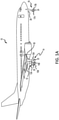
- an aircraft 10 includes landing gear, such as a left main landing gear 12, a right main landing gear 14, and nose landing gear 16.
- the left main landing gear 12, right main landing gear 14, and nose landing gear 16 typically support the aircraft 10 when the aircraft 10 is not flying, thereby allowing the aircraft 10 to taxi, take off, and land without damage.
- the left main landing gear 12 includes a first wheel 13A and a second wheel 13B coupled by an axle 20.
- the right main landing gear 14 includes a first wheel 15A and a second wheel 15B coupled by an axle 22.
- the nose landing gear 16 includes a first nose wheel 17A and a second nose wheel 17B coupled by an axle 24.
- the aircraft 10 comprises any number of landing gear(s), and each landing gear comprises any number of wheels.
- the left main landing gear 12, right main landing gear 14, and nose landing gear 16 are retracted when the aircraft 10 is in flight.
- one or more of the left main landing gear 12, right main landing gear 14, and nose landing gear 16 extends from an underside of a fuselage 28 of the aircraft 10, or from an underside of the wings 30 thereof.
- the aircraft 10 also includes a brake system that is applied to one or more of the wheels 13A, 13B, 15A, 15B, 17A, 17B of one or more of the respective left main landing gear 12, right main landing gear 14, and/or nose landing gear 16.
- brake systems of the aircraft 10 typically comprise a collection of assemblies, subsystems, and/or units that produce output signals for controlling the braking force and/or torque applied at one or more of the wheels 13A, 13B, 15A, 15B, 17A, 17B.
- Such brake systems typically communicate with the brakes of the left main landing gear 12, right main landing gear 14, and/or nose landing gear 16, and each brake is typically mounted to each wheel 13A, 13B, 15A, 15B, 17A, 17B in order to apply and release braking forces thereon.
- the brakes of the aircraft 10 further include a non-rotatable wheel support, the wheels 13A, 13B, 15A, 15B, 17A, 17B mounted to the wheel support for rotation, and a brake disk stack.
- a brake assembly 110 for an aircraft such as aircraft 10 of FIG. 1A
- the brake assembly 110 interfaces with a bogie axle 112 and a wheel 114 (e.g., the wheels 13A, 13B, 15A, 15B, 17A, 17B of FIG. 1A ) of the aircraft 10.
- the wheel 114 may include a hub 116, a disk 120 (also referred to as a web portion of a wheel), and a rim 118 (also referred to as a flange portion of a wheel).
- the wheel assembly and/or brake assembly 110 generally includes a torque take-out assembly (also referred to as a torque plate or a torque plate assembly) 122, one or more torque bars 124, a wheel rotational axis 126, a wheel well cavity 128, an actuator 130, multiple brake rotors 32, multiple brake stators 34, a pressure plate 36, an end plate 38, a heat shield 140, multiple torque bar bolts 148, a torque bar pin 151, a torque bar retention slot 152, multiple rotor lugs 154, and multiple stator slots 156, according to various embodiments.
- a torque take-out assembly also referred to as a torque plate or a torque plate assembly
- Brake disks e.g., the interleaved brake rotors 32 and brake stators 34
- the brake rotors 32 are typically secured to the torque bars 124, which are coupled to the rim 118 of the wheel 114, for rotating with the wheel 114.
- the brake stators 34 are typically engaged with the torque take-out assembly (e.g., torque plate assembly) 122.
- At least one actuator 130 is typically operable to compress the interleaved brake rotors 32 and brake stators 34 for stopping the aircraft 10 of FIG. 1A .
- the actuator 130 is shown as a hydraulically actuated piston, though electronically actuated pistons are contemplated herein.
- the pressure plate 36 and end plate 38 are disposed at opposite ends of the interleaved brake rotors 32 and brake stators 34.
- the torque take-out assembly 122 is typically secured to a stationary portion of a landing gear truck, such as a bogie beam or other landing gear strut, such that the torque take-out assembly 122 and brake stators 34 are prevented from rotating during braking of the aircraft 10 of FIG. 1A .
- the brake rotors 32 and brake stators 34 are typically fabricated from various materials, such as, for example carbon materials.
- the brake disks typically withstand and dissipate the heat generated from contact between the brake disks while braking the aircraft 10 of FIG. 1A .
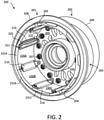
- a wheel assembly 200 which may be similar to wheels 13A, 13B, 15A, 15B, 17A, 17B of FIG. 1A , is provided.
- the wheel assembly 200 may be a split wheel assembly and thus may comprise an inboard wheel portion 201 and an outboard wheel portion 202. Wheel portions 201, 202, for example, may be referred to as wheel halves.
- the wheel assembly 200 may be implemented with any landing gear of the aircraft 10 (e.g., any of the landing gears mentioned above with reference to FIG. 1A ), and the wheel assembly 200 may be an inner/inboard wheel assembly or an outer/outboard assembly.
- wheel assembly 200 Although numerous details are included herein pertaining to the implementation of the wheel assembly 200 in an aircraft, one skilled in the art will realize that a similar wheel assembly may be used in other vehicles, such as cars or motorcycles, and thus the scope of the present disclosure is not necessarily limited to aircraft wheel assemblies.
- inboard wheel portion 201 of wheel assembly 200 comprises a hub 206, a disk 205, and a rim 204.
- Radially outward surface of the rim 204 may define a tube-well 203. That is, tube-well 203 may be defined by respective flange sections of the inboard wheel portion 201 and the outboard wheel portion 202.
- the rim 204/tube-well 203 may be configured to receive a tire and may form a seal with tire to allow pressurized air to inflate the tire.
- the inboard wheel portion 201 also includes a radially outward extending lip 208 located at an inboard end of the inboard wheel portion 201, and the outboard wheel portion 202 may also include a similar radially outward extending lip or rim 209 located at an outboard end of the outboard wheel portion 202.
- wheel assembly 200 includes tie bolts 207 that extend through the disk 205 to hold together the wheel portions 201, 202.
- Radially inward of, and generally defined by, the radially inward surface of the rim 204 is the wheel well cavity (e.g., 128 in FIG. 1B ) where the brake assembly 110 is disposed. That is, the wheel well cavity 128 ( FIG. 1B ) generally refers to the volume bound by the rim 204 and the disk 205, according to various embodiments.
- the wheel assembly 200 includes, according to various embodiments, one or more retainers 210 and one or more torque bars 220. In FIG. 2 , some of the torque bars 220 are omitted in order to clearly show the retainers 210.
- each retainer 210 is disposed radially between a respective torque bar 220 and the radially inward surface of the rim 204, according to various embodiments.
- each torque bar 220 may be mounted to the rim 204 using a torque bar bolt 221 and an outboard end of each torque bar 220 may be mounted to the disk 205 via insertion of a torque bar pin 222 into a torque bar retention slot 152 of the disk 205.
- Each retainer 210 may be coupled to a respective torque bar 220, as described in greater detail below.
- the retainers 210 may be configured to engage and secure heat shield segments, such as heat shield segments 230A, 230B, 230C.
- each heat shield segment 230A, 230B, 230C collectively form a segmented annular heat shield, and each of these segments 230A, 230B, 230C is held in place between circumferentially adjacent retainers 210, according to various embodiments. Additionally, the retainers 210 may provide a heat shielding benefit, as described in greater detail below.
- the each heat shield segment 230A, 230B, 230C is a laminated, dimpled foil metallic heat shield.
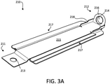
- the retainer 210 may include a first end 211, a second end 212 opposite the first end 211, and a body 215 extending between the first end 211 and the second end 212.
- the body 215 may include opposing longitudinal sides 217 that are configured to respectively engage and secure a respective heat shield of the segmented annular heat shield.
- each of the opposing longitudinal sides 217 of the body 215 of the retainer 210 may include/define a groove for receiving an edge of the respective heat shield segment.
- the first end 211 and the second end 212 of the retainer 210 are both configured to be coupled to the wheel (rim 204 or disk 205) and/or the torque bar 220.
- the first end 211 of the retainer 210 may define a first aperture 213 for receiving the torque bar bolt 221, and thus the torque bar bolt 221 may extend through both the inboard end of the torque bar and the first end 211 of the retainer 210.
- the second end 212 of the retainer 210 may comprise a flange 216, and the flange 216 may define a second aperture 214 through which the torque bar pin 222 of the torque bar 220 is inserted.
- the second aperture 214 defined in the flange 216 may fit around the torque bar pin 222 in order to secure the second end 212 relative to the torque bar 220.
- the flange extends radially inward. Accordingly, because the body 215 of the retainer 210 may extend substantially axially (e.g., parallel to the rotational axis of the wheel assembly 200), the flange 216 may be substantially perpendicular to the body 215, and thus the first aperture 213 and the second aperture 214 may lie in substantially perpendicular planes.
- the retainer 210 also includes a shoulder 218, which may be positioned at the first end 211, at the second end 212, or along the body 215, and the shoulder 218 may be configured to engage the torque bar 220 in order to maintain the retainer 210 in a desired position and/or orientation relative to the torque bar 220.
- the wheel assembly 200 may further include a torque bar spacer 240 coupled to an inboard end of the torque bar 220.
- the first end 211 of the retainer 210 may be compressed between the inboard end of the torque bar 220 and the torque bar spacer 240 (compression may be produced via the preloaded/tensioned torque bar bolt 221).
- the torque bar spacer 240 may include one or more fasteners 241 for securing the respective heat shield segments to the inboard end of the torque bar 220. That is, in response to the individual heat shield segments being installed between adjacent retainer 210, the inboard edge of the heat shield segments may be secured from sliding by coupling said segments to the torque bar spacer 240 using fasteners 241.
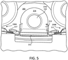
- an axial-looking view of the retainer 210 is provided, with adjacent heat shield segments 230A, 230B being secured to the retainer 210. That is, corresponding edges of the heat shield segments 230A, 230B are received into the longitudinal sides 217 (e.g., grooves) of the retainer 210, according to various embodiments. Engagement between the edges of the heat shield segments 230A, 230B and the longitudinal sides 217 of the retainer 210 may be an interference fit.
- the torque bar is omitted in order to clearly show the elements/features of the retainer 210.
- FIG. 5 the torque bar is omitted in order to clearly show the elements/features of the retainer 210.
- FIG. 5 shows how the aperture 214 defined in the flange 216 at the second end 212 of the retainer is aligned with the torque bar retention slot 152 defined in the disk 205 (e.g., web) of the inboard wheel portion 201 ( FIG. 2 ), according to various embodiments.
- FIGS. 6A and 6B multiple heat shield segments 230A, 230B, 230C are provided, with one of the heat shield segments (230B) shown in a partially installed state. More specifically, FIGS. 6A and 6B , according to various embodiments, show how the individual heat shield segments may be installed. With the retainers 210 and the torque bars 220 installed/mounted to the inboard wheel portion 201 ( FIG.
- the individual heat shield segments such as heat shield segment 230B
- the individual heat shield segments may be aligned and engaged with the longitudinal sides 217 of the circumferentially adjacent retainers 210 and may be subsequently slid along the longitudinal sides 217 of the retainers 210 in an axially outboard direction until an outboard edge of the heat shield segment 230B is adjacent the disk 205 of the inboard wheel portion 201.
- the wheel assembly 200 may include a plurality of pairs of torque bars 220 and retainers 210, with each pair being circumferentially distributed around the radially inward surface of the rim 204 ( FIG. 2 ) and with each heat shield segment of the plurality of heat shield segments 230A, 230B, 230C being disposed and secured between circumferentially adjacent retainers 210.
- the inboard edges 231A, 231B, 231C of the plurality of heat shield segments 230A, 230B, 230C collectively form a chin ring of the wheel assembly.
- the chin ring may be hoop/ring that extends farther inboard (see FIG. 6B ) than the inboard lip 208 of the inboard wheel portion 201 of the wheel assembly 200.
- the chin ring may provide a thermal barrier to prevent heat radiation from reaching a tire disposed around the wheel in the tube-well 203.
- a cross-section of the torque bar 220 and the retainer 210 is provided.
- a longitudinal axis of the retainer 210 may not be exactly parallel with a longitudinal axis of the torque bar 220.
- the second end 212 of the retainer 210 may be radially inward of the first end 211.
- Such a configuration may be to ensure clearance between the second end 212 of the retainer 210 and the rim 204 of the wheel. Further, such a configuration may promote convective heat flow out of the inboard side of the wheel.
- the retainer 210 may be oriented in a slightly radially inward direction from the first end 211 to the second end 212 in order to more securely engage the outboard ends of the heat shield segments. Further, the retainer 210 may, in addition to providing a means for retaining the heat shield segments, function as a heat shield by dividing the volume radially outward of the torque bar 220 into two volumes. That is, the retainer 210 may define two air gaps 219A, 219B between the torque bar 220 and the radially inward surface of the rim 204.
- a schematic flow chart diagram of a method 890 of assembling a wheel assembly may include mounting a first torque bar to a wheel with a first retainer disposed between the torque bar and the wheel at step 892.
- the method 890 may further include mounting a second torque bar to wheel with a second retainer disposed between the second torque bar and the wheel at step 894.
- the method 890 may include engaging lateral edges of a heat shield segment with the first retainer and the second retainer at step 896.
- steps 892 and 894 include radially positioning the first and second retainers, respectively, between the respective torque bars and a radially inward surface of an inboard wheel portion of the wheel.
- step 896 includes axially sliding, in an outboard direction, the heat shield segment between the first retainer and the second retainer such that the lateral edges of the segment slide through grooves respectively defined by the first retainer and the second retainer.
- the method 890 further includes, before step 892, inserting a torque bar pin of the first torque bar through an aperture defined in a flange at an end of the first retainer.
- mounting the first torque bar to the inboard wheel portion may comprise inserting the first torque bar pin into a torque bar retention slot defined in a web of the inboard wheel portion of the wheel assembly.
- a cover 250 for the retainer 210 is provided.
- the cover 250 provides additional thermal/heat protection by defining an additional air gap 259 between the retainer 210 and the cover 250.
- the cover 250 is coupled to the retainer 210.
- the cover 250 may be coupled to and may extend over at least the body 215 of the retainer 210, and thus the cover 250 and the retainer 210 together may improve the thermal protection of the wheel assembly by inhibiting heat transfer through the retainer 210 and cover 250.
- the cover 250 is detachably coupled to the body 215 of the retainer 210, and thus once installed may be generally disposed between the first end 211 and the second 212 of the retainer 210.
- the cover 250 may be configured to slide over/onto the body 215 of the retainer 210.
- the cover 250 may have opposing longitudinal edges 257 that respectively wrap around and are disposed within the groove 217 of the opposing longitudinal sides of the retainer 210.
- the opposing longitudinal edges 257 of the cover 250 may be referred to herein as wrap-around edges 257, and these wrap-around edges 257 may be slid into engagement with the opposing longitudinal sides 217 of the retainer 210.
- the body 215 of the retainer 210 includes at least one tab 251, disposed proximate the first end 211 of the retainer 210, that is configured to be bent or otherwise plastically deformed after the cover 250 has been slid onto the body 215 of the retainer 210, thereby securing the cover 250 in place.
- the body 215 and/or the second end 212 of the retainer 210 may also include a shoulder 258 against which the cover 250 engages such that the cover 250 is held in place between the shoulder 258 and the at least one tab 251 to maintain at least one of a position and an orientation of the cover 250 relative to the retainer 210.
- This shoulder 258, according to various embodiments, is different than above mentioned shoulder 218. That is, shoulder 258 may be a first shoulder, and shoulder 218 may be a second shoulder.
- an axial-looking view of the retainer 210 and cover 250 is provided, with adjacent heat shield segments 230A, 230B being secured to the retainer 210.
- the torque bar 220 is omitted in order to clearly show the elements/features of the retainer 210 and the cover 250.
- Corresponding edges of the heat shield segments 230A, 230B are received into the longitudinal sides 217 (e.g., grooves) of the retainer 210, according to various embodiments. Engagement between the edges of the heat shield segments 230A, 230B and the longitudinal sides 217 of the retainer 210 may be an interference fit.
- the wrap-around edges 257 of the cover 250 are disposed in the grooves 217, and thus the wrap-around edges 257 of the cover 250 may contact the corresponding edges of the heat shield segments. Accordingly, the compression/interference fit of the edges of the heat shield segments 230A, 230B may be caused by direct contact between a surface of the grooves 217 of the retainer 210 and the wrap-around edges 257 of the cover 250.
- the cover 250 is disposed radially inward of the retainer 210.
- a cross-section of the torque bar 220, the cover 250, and the retainer 210 is provided.
- the inclusion of the cover 250 may, as mentioned above, inhibit heat transfer through the area radially outward of the torque bar 220 by defining an extra air gap. That is, the volume radially outward of the torque bar 220 is divided into three air gaps.
- a first air gap 219A is defined between the torque bar 220 and the cover 250
- a second air gap 259 is defined between the cover 250 and the retainer 210
- a third air gap 219B is defined between the retainer 210 and the radially inward surface of the rim 204 of the inboard wheel portion 201 ( FIG. 2 ).
- a schematic flow chart diagram of a method 990 of assembling a wheel assembly includes coupling a cover to a retainer at step 992 and mounting a torque bar to a wheel, with the retainer disposed between the torque bar and the wheel at step 994.
- the method 990 further includes engaging a lateral edge of a heat shield segment with the retainer at step 996.
- Three air gaps e.g., a first air gap, a second air gap, and a third air gap
- step 994 includes mounting the torque bar to an inboard wheel portion of the wheel assembly such that the retainer is disposed between the torque bar and a radially inward surface of a rim of the inboard wheel portion.
- step 992 of the method 990 may include sliding the cover over a body of the retainer and subsequently bending at least one tab to secure the cover in place.
- any reference to attached, fixed, connected, coupled or the like may include permanent (e.g., integral), removable, temporary, partial, full, and/or any other possible attachment option.
- permanent e.g., integral
- removable temporary, partial, full
- any other possible attachment option e.g., permanent, temporary, partial, full, and/or any other possible attachment option.
- Different cross-hatching is used throughout the figures to denote different parts but not necessarily to denote the same or different materials.
- any of the method or process descriptions may be executed in any order and are not necessarily limited to the order presented.
- any reference to singular includes plural embodiments, and any reference to more than one component or step may include a singular embodiment or step.
- Elements and steps in the figures are illustrated for simplicity and clarity and have not necessarily been rendered according to any particular sequence. For example, steps that may be performed concurrently or in different order are illustrated in the figures to help to improve understanding of embodiments of the present disclosure.
- Any reference to attached, fixed, connected or the like may include permanent, removable, temporary, partial, full and/or any other possible attachment option. Additionally, any reference to without contact (or similar phrases) may also include reduced contact or minimal contact. Surface shading lines may be used throughout the figures to denote different parts or areas but not necessarily to denote the same or different materials. In some cases, reference coordinates may be specific to each figure.
- references to "one embodiment”, “an embodiment”, “various embodiments”, etc. indicate that the embodiment described may include a particular feature, structure, or characteristic, but every embodiment may not necessarily include the particular feature, structure, or characteristic. Moreover, such phrases are not necessarily referring to the same embodiment. Further, when a particular feature, structure, or characteristic is described in connection with an embodiment, it is submitted that it is within the knowledge of one skilled in the art to affect such feature, structure, or characteristic in connection with other embodiments whether or not explicitly described. After reading the description, it will be apparent to one skilled in the relevant art(s) how to implement the disclosure in alternative embodiments.
Landscapes
- Engineering & Computer Science (AREA)
- Mechanical Engineering (AREA)
- General Engineering & Computer Science (AREA)
- Aviation & Aerospace Engineering (AREA)
- Transportation (AREA)
- Physics & Mathematics (AREA)
- Fluid Mechanics (AREA)
- Braking Arrangements (AREA)
Description
- The present disclosure relates to wheel assemblies, and more specifically to a cover coupled to a retainer for a segmented annular heat shield of a wheel assembly.
- Aircraft typically include landing gear for supporting the aircraft above a ground surface and for allowing the aircraft to move relative to the ground surface while remaining supported by the ground surface. The landing gear may include one or more wheel assemblies. Most wheel assemblies include a brake assembly to decelerate or park the aircraft. Aircraft braking, especially during landing, tends to generate significant heat that can damage components of the wheel assembly if such components are not properly shielded. While annular heat shields provide thermal protection, the logistics of assembling, repairing, and/or replacing conventional annular heat shields are burdensome.
ES2315540T3 EP1516754A1 relates to a heat shield assembly for an aircraft wheel and brake assembly. - Disclosed herein, according to various embodiments, is a wheel assembly according to claim 1. The wheel assembly includes an inboard wheel portion having a rim and a disk. A radially inward surface of the rim and an inboard surface of the disk defines a wheel well cavity configured to house a brake assembly. The wheel assembly also includes a torque bar (e.g., a torque bar of the brake assembly) mounted to the inboard wheel portion. Further, the wheel assembly includes a retainer coupled to the torque bar and disposed radially between the torque bar and the radially inward surface of the rim of the inboard wheel portion. The retainer includes opposing longitudinal sides configured to respectively engage and retain a respective heat shield segment of a segmented annular heat shield. The wheel assembly further includes a cover coupled to at least a portion of the retainer, with a first gap, a second gap, and a third gap being defined between the torque bar and the radially inward surface of the rim of the inboard wheel portion. The cover is disposed radially between the torque bar and the retainer, the first air gap is defined between the torque bar and the cover, the second air gap is defined between the cover and the retainer, and the third air gap is defined between the retainer and the radially inward surface of the rim of the inboard wheel portion. Preferred embodiments are provided in the dependent claims.
- Also disclosed herein, according to various embodiments, is a method of assembling a wheel assembly. The method includes coupling a cover to a retainer, mounting a torque bar to an inboard wheel portion of the wheel assembly such that a retainer is disposed between the torque bar and a radially inward surface of a rim of the inboard wheel portion. The method further includes engaging a lateral edge of a heat shield segment with the retainer. Coupling the cover to the retainer may include sliding the cover over a body of the retainer and subsequently bending at least one tab to secure the cover in place.
- The forgoing features and elements may be combined in various combinations without departing from the scope of the appended claims. These features and elements as well as the operation of the disclosed embodiments will become more apparent in light of the following description and accompanying drawings.
-
-
FIG. 1A illustrates an aircraft having multiple landing gear, in accordance with various embodiments; -
FIG. 1B illustrates a brake assembly, in accordance with various embodiments; -
FIG. 2 is a perspective view of a wheel assembly, in accordance with various embodiments; -
FIG. 3 is a perspective view of a retainer for a segmented annular heat shield, in accordance with various embodiments; -
FIG. 4 is a perspective view of a torque bar and a retainer for a segmented annular heat shield coupled to an inboard wheel portion of a wheel assembly, in accordance with various embodiments; -
FIG. 5 is an axial view of a retainer, with a torque bar not shown, securing adjacent heat shield segments of a segmented annular heat shield, in accordance with various embodiments; -
FIGS. 6A and 6B show a heat shield segment being installed between adjacent retainers, in accordance with various embodiments; -
FIG. 7 shows a cross-section of a torque bar and a retainer disposed radially between the torque bar and a rim of an inboard wheel portion, in accordance with various embodiments; -
FIG. 8 is a schematic flow chart diagram of a method of assembling a wheel assembly, in accordance with various embodiments; -
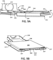
FIGS. 9A, 9B ,9C, and 9D are various views of a cover coupled to a retainer for a segmented annular heat shield, in accordance with various embodiments; -
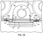
FIG. 10 is an axial view of a cover coupled to a retainer, with a torque bar not shown, securing adjacent heat shield segments of a segmented annular heat shield, in accordance with various embodiments; -
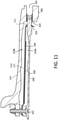
FIG. 11 shows a cross-section of a torque bar, a retainer, and a cover for the retainer disposed radially inward of a rim of an inboard wheel portion, in accordance with various embodiments; and -
FIG. 12 is a schematic flow chart diagram of a method of assembling a wheel assembly, in accordance with various embodiments. - The subject matter of the present disclosure is particularly pointed out and distinctly claimed in the concluding portion of the specification. A more complete understanding of the present disclosure, however, may best be obtained by referring to the detailed description and claims when considered in connection with the drawing figures.
- The detailed description of exemplary embodiments herein makes reference to the accompanying drawings, which show exemplary embodiments by way of illustration. While these exemplary embodiments are described in sufficient detail to enable those skilled in the art to practice the disclosure, it should be understood that other embodiments may be realized and that logical changes and adaptations in design and construction may be made in accordance with this disclosure and the teachings herein without departing from the scope of the appended claims. Thus, the detailed description herein is presented for purposes of illustration only and not of limitation.
- As used herein, a first component that is "radially outward" of a second component means that the first component is positioned at a greater distance away from a common axis than the second component. A first component that is "radially inward" of a second component means that the first component is positioned closer to the common axis than the second component. In the case of components that rotate circumferentially about a common axis, a first component that is radially inward of a second component rotates through a circumferentially shorter path than the second component. As used herein, "distal" refers to the direction outward, or generally, away from a reference component. As used herein, "proximal" and/or "proximate" refer to a direction inward, or generally, towards the reference component.
- Referring now to
FIG. 1A , in accordance with various embodiments, anaircraft 10 includes landing gear, such as a leftmain landing gear 12, a rightmain landing gear 14, andnose landing gear 16. The leftmain landing gear 12, rightmain landing gear 14, andnose landing gear 16 typically support theaircraft 10 when theaircraft 10 is not flying, thereby allowing theaircraft 10 to taxi, take off, and land without damage. In various embodiments, the leftmain landing gear 12 includes afirst wheel 13A and asecond wheel 13B coupled by anaxle 20. In various embodiments, the rightmain landing gear 14 includes afirst wheel 15A and asecond wheel 15B coupled by anaxle 22. In various embodiments, thenose landing gear 16 includes afirst nose wheel 17A and asecond nose wheel 17B coupled by anaxle 24. In various embodiments, theaircraft 10 comprises any number of landing gear(s), and each landing gear comprises any number of wheels. In various embodiments, the leftmain landing gear 12, rightmain landing gear 14, andnose landing gear 16 are retracted when theaircraft 10 is in flight. In various embodiments, one or more of the leftmain landing gear 12, rightmain landing gear 14, andnose landing gear 16 extends from an underside of afuselage 28 of theaircraft 10, or from an underside of thewings 30 thereof. - In various embodiments, the
aircraft 10 also includes a brake system that is applied to one or more of thewheels main landing gear 12, rightmain landing gear 14, and/ornose landing gear 16. Such brake systems of theaircraft 10 typically comprise a collection of assemblies, subsystems, and/or units that produce output signals for controlling the braking force and/or torque applied at one or more of thewheels main landing gear 12, rightmain landing gear 14, and/ornose landing gear 16, and each brake is typically mounted to eachwheel aircraft 10 further include a non-rotatable wheel support, thewheels - Referring now to
FIG. 1B , abrake assembly 110 for an aircraft, such asaircraft 10 ofFIG. 1A , is provided, in accordance with various embodiments. Thebrake assembly 110 interfaces with abogie axle 112 and a wheel 114 (e.g., thewheels FIG. 1A ) of theaircraft 10. Thewheel 114 may include ahub 116, a disk 120 (also referred to as a web portion of a wheel), and a rim 118 (also referred to as a flange portion of a wheel). The wheel assembly and/orbrake assembly 110 generally includes a torque take-out assembly (also referred to as a torque plate or a torque plate assembly) 122, one ormore torque bars 124, a wheelrotational axis 126, awheel well cavity 128, anactuator 130,multiple brake rotors 32,multiple brake stators 34, apressure plate 36, an end plate 38, aheat shield 140, multipletorque bar bolts 148, atorque bar pin 151, a torquebar retention slot 152, multiple rotor lugs 154, andmultiple stator slots 156, according to various embodiments. - Brake disks (e.g., the interleaved
brake rotors 32 and brake stators 34) are disposed in thewheel well cavity 128 that is generally and collectively defined by therim 118, thedisk 120, and thehub 116. Thebrake rotors 32 are typically secured to the torque bars 124, which are coupled to therim 118 of thewheel 114, for rotating with thewheel 114. The brake stators 34 are typically engaged with the torque take-out assembly (e.g., torque plate assembly) 122. At least oneactuator 130 is typically operable to compress the interleavedbrake rotors 32 andbrake stators 34 for stopping theaircraft 10 ofFIG. 1A . In the embodiment ofFIG. 1B , theactuator 130 is shown as a hydraulically actuated piston, though electronically actuated pistons are contemplated herein. Thepressure plate 36 and end plate 38 are disposed at opposite ends of the interleavedbrake rotors 32 andbrake stators 34. - Through compression of the
brake rotors 32 andbrake stators 34 between thepressure plate 36 and end plate 38, the resulting frictional contact slows, stops, and/or prevents rotation of thewheel 114. The torque take-outassembly 122 is typically secured to a stationary portion of a landing gear truck, such as a bogie beam or other landing gear strut, such that the torque take-outassembly 122 andbrake stators 34 are prevented from rotating during braking of theaircraft 10 ofFIG. 1A . Thebrake rotors 32 andbrake stators 34 are typically fabricated from various materials, such as, for example carbon materials. The brake disks typically withstand and dissipate the heat generated from contact between the brake disks while braking theaircraft 10 ofFIG. 1A . - According to various embodiments and with reference to
FIG. 2 , awheel assembly 200, which may be similar towheels FIG. 1A , is provided. Thewheel assembly 200 may be a split wheel assembly and thus may comprise aninboard wheel portion 201 and anoutboard wheel portion 202.Wheel portions wheel assembly 200 may be implemented with any landing gear of the aircraft 10 (e.g., any of the landing gears mentioned above with reference toFIG. 1A ), and thewheel assembly 200 may be an inner/inboard wheel assembly or an outer/outboard assembly. Although numerous details are included herein pertaining to the implementation of thewheel assembly 200 in an aircraft, one skilled in the art will realize that a similar wheel assembly may be used in other vehicles, such as cars or motorcycles, and thus the scope of the present disclosure is not necessarily limited to aircraft wheel assemblies. - In various embodiments,
inboard wheel portion 201 ofwheel assembly 200 comprises ahub 206, adisk 205, and arim 204. Radially outward surface of therim 204 may define a tube-well 203. That is, tube-well 203 may be defined by respective flange sections of theinboard wheel portion 201 and theoutboard wheel portion 202. Therim 204/tube-well 203 may be configured to receive a tire and may form a seal with tire to allow pressurized air to inflate the tire. In various embodiments, theinboard wheel portion 201 also includes a radially outward extendinglip 208 located at an inboard end of theinboard wheel portion 201, and theoutboard wheel portion 202 may also include a similar radially outward extending lip or rim 209 located at an outboard end of theoutboard wheel portion 202. - In various embodiments,
wheel assembly 200 includestie bolts 207 that extend through thedisk 205 to hold together thewheel portions rim 204 is the wheel well cavity (e.g., 128 inFIG. 1B ) where thebrake assembly 110 is disposed. That is, the wheel well cavity 128 (FIG. 1B ) generally refers to the volume bound by therim 204 and thedisk 205, according to various embodiments. Thewheel assembly 200 includes, according to various embodiments, one ormore retainers 210 and one or more torque bars 220. InFIG. 2 , some of the torque bars 220 are omitted in order to clearly show theretainers 210. Generally, eachretainer 210 is disposed radially between arespective torque bar 220 and the radially inward surface of therim 204, according to various embodiments. - For example, an inboard end of each
torque bar 220 may be mounted to therim 204 using atorque bar bolt 221 and an outboard end of eachtorque bar 220 may be mounted to thedisk 205 via insertion of atorque bar pin 222 into a torquebar retention slot 152 of thedisk 205. Eachretainer 210 may be coupled to arespective torque bar 220, as described in greater detail below. Generally, theretainers 210 may be configured to engage and secure heat shield segments, such asheat shield segments heat shield segments segments adjacent retainers 210, according to various embodiments. Additionally, theretainers 210 may provide a heat shielding benefit, as described in greater detail below. In various embodiments, the eachheat shield segment - In various embodiments, and with reference to
FIG. 3A , a perspective view of theretainer 210 is provided. Theretainer 210 may include afirst end 211, asecond end 212 opposite thefirst end 211, and abody 215 extending between thefirst end 211 and thesecond end 212. Thebody 215 may include opposinglongitudinal sides 217 that are configured to respectively engage and secure a respective heat shield of the segmented annular heat shield. For example, each of the opposinglongitudinal sides 217 of thebody 215 of theretainer 210 may include/define a groove for receiving an edge of the respective heat shield segment. - In various embodiments, and with reference to
FIGS. 2 and3 , thefirst end 211 and thesecond end 212 of theretainer 210 are both configured to be coupled to the wheel (rim 204 or disk 205) and/or thetorque bar 220. For example, thefirst end 211 of theretainer 210 may define afirst aperture 213 for receiving thetorque bar bolt 221, and thus thetorque bar bolt 221 may extend through both the inboard end of the torque bar and thefirst end 211 of theretainer 210. Thesecond end 212 of theretainer 210 may comprise aflange 216, and theflange 216 may define asecond aperture 214 through which thetorque bar pin 222 of thetorque bar 220 is inserted. That is, thesecond aperture 214 defined in theflange 216 may fit around thetorque bar pin 222 in order to secure thesecond end 212 relative to thetorque bar 220. In various embodiments, the flange extends radially inward. Accordingly, because thebody 215 of theretainer 210 may extend substantially axially (e.g., parallel to the rotational axis of the wheel assembly 200), theflange 216 may be substantially perpendicular to thebody 215, and thus thefirst aperture 213 and thesecond aperture 214 may lie in substantially perpendicular planes. In various embodiments, theretainer 210 also includes ashoulder 218, which may be positioned at thefirst end 211, at thesecond end 212, or along thebody 215, and theshoulder 218 may be configured to engage thetorque bar 220 in order to maintain theretainer 210 in a desired position and/or orientation relative to thetorque bar 220. - In various embodiments, and with reference to
FIG. 4 , a view of theretainer 210 disposed between thetorque bar 220 and the radially inward surface of therim 204 of the inboard wheel portion 201 (FIG. 2 ) is provided. InFIG. 2 the heat shield segments have yet to be installed, and further details pertaining to the installation/assembly method are provided below with reference toFIG. 8 . In various embodiments, thewheel assembly 200 may further include atorque bar spacer 240 coupled to an inboard end of thetorque bar 220. Thefirst end 211 of theretainer 210 may be compressed between the inboard end of thetorque bar 220 and the torque bar spacer 240 (compression may be produced via the preloaded/tensioned torque bar bolt 221). Thetorque bar spacer 240 may include one ormore fasteners 241 for securing the respective heat shield segments to the inboard end of thetorque bar 220. That is, in response to the individual heat shield segments being installed betweenadjacent retainer 210, the inboard edge of the heat shield segments may be secured from sliding by coupling said segments to thetorque bar spacer 240 usingfasteners 241. - In various embodiments, and with reference to
FIG. 5 , an axial-looking view of theretainer 210 is provided, with adjacentheat shield segments retainer 210. That is, corresponding edges of theheat shield segments retainer 210, according to various embodiments. Engagement between the edges of theheat shield segments longitudinal sides 217 of theretainer 210 may be an interference fit. InFIG. 5 , the torque bar is omitted in order to clearly show the elements/features of theretainer 210. Thus,FIG. 5 shows how theaperture 214 defined in theflange 216 at thesecond end 212 of the retainer is aligned with the torquebar retention slot 152 defined in the disk 205 (e.g., web) of the inboard wheel portion 201 (FIG. 2 ), according to various embodiments. - In various embodiments, and with reference to
FIGS. 6A and 6B , multipleheat shield segments FIGS. 6A and 6B , according to various embodiments, show how the individual heat shield segments may be installed. With theretainers 210 and the torque bars 220 installed/mounted to the inboard wheel portion 201 (FIG. 2 ), the individual heat shield segments, such asheat shield segment 230B, may be aligned and engaged with thelongitudinal sides 217 of the circumferentiallyadjacent retainers 210 and may be subsequently slid along thelongitudinal sides 217 of theretainers 210 in an axially outboard direction until an outboard edge of theheat shield segment 230B is adjacent thedisk 205 of theinboard wheel portion 201. Accordingly, thewheel assembly 200 may include a plurality of pairs oftorque bars 220 andretainers 210, with each pair being circumferentially distributed around the radially inward surface of the rim 204 (FIG. 2 ) and with each heat shield segment of the plurality ofheat shield segments adjacent retainers 210. - In various embodiments, and with reference to
FIGS. 2 ,6A, and 6B , theinboard edges heat shield segments FIG. 6B ) than theinboard lip 208 of theinboard wheel portion 201 of thewheel assembly 200. The chin ring may provide a thermal barrier to prevent heat radiation from reaching a tire disposed around the wheel in the tube-well 203. - In various embodiments, and with reference to
FIG. 7 , a cross-section of thetorque bar 220 and theretainer 210 is provided. In various embodiments, a longitudinal axis of theretainer 210 may not be exactly parallel with a longitudinal axis of thetorque bar 220. Said differently, thesecond end 212 of theretainer 210 may be radially inward of thefirst end 211. Such a configuration may be to ensure clearance between thesecond end 212 of theretainer 210 and therim 204 of the wheel. Further, such a configuration may promote convective heat flow out of the inboard side of the wheel. That is, hot airflow may engage the angled/inclined surface of theretainer 210 and may be directed inboard along theretainer 210 to escape the wheel cavity. In various embodiments, theretainer 210 may be oriented in a slightly radially inward direction from thefirst end 211 to thesecond end 212 in order to more securely engage the outboard ends of the heat shield segments. Further, theretainer 210 may, in addition to providing a means for retaining the heat shield segments, function as a heat shield by dividing the volume radially outward of thetorque bar 220 into two volumes. That is, theretainer 210 may define twoair gaps torque bar 220 and the radially inward surface of therim 204. - In various embodiments, and with reference to
FIG. 8 , a schematic flow chart diagram of amethod 890 of assembling a wheel assembly is provided. Themethod 890 may include mounting a first torque bar to a wheel with a first retainer disposed between the torque bar and the wheel atstep 892. Themethod 890 may further include mounting a second torque bar to wheel with a second retainer disposed between the second torque bar and the wheel atstep 894. Still further, themethod 890 may include engaging lateral edges of a heat shield segment with the first retainer and the second retainer atstep 896. - In various embodiments,
steps step 896 includes axially sliding, in an outboard direction, the heat shield segment between the first retainer and the second retainer such that the lateral edges of the segment slide through grooves respectively defined by the first retainer and the second retainer. In various embodiments, themethod 890 further includes, beforestep 892, inserting a torque bar pin of the first torque bar through an aperture defined in a flange at an end of the first retainer. In such embodiments, mounting the first torque bar to the inboard wheel portion may comprise inserting the first torque bar pin into a torque bar retention slot defined in a web of the inboard wheel portion of the wheel assembly. - In various embodiments, and with reference to
FIGS. 9A, 9B ,9C, and 9D , acover 250 for theretainer 210 is provided. Generally, thecover 250 provides additional thermal/heat protection by defining anadditional air gap 259 between theretainer 210 and thecover 250. In various embodiments, thecover 250 is coupled to theretainer 210. Thecover 250 may be coupled to and may extend over at least thebody 215 of theretainer 210, and thus thecover 250 and theretainer 210 together may improve the thermal protection of the wheel assembly by inhibiting heat transfer through theretainer 210 andcover 250. - In various embodiments, the
cover 250 is detachably coupled to thebody 215 of theretainer 210, and thus once installed may be generally disposed between thefirst end 211 and the second 212 of theretainer 210. For example, thecover 250 may be configured to slide over/onto thebody 215 of theretainer 210. Thecover 250 may have opposinglongitudinal edges 257 that respectively wrap around and are disposed within thegroove 217 of the opposing longitudinal sides of theretainer 210. Thus, the opposinglongitudinal edges 257 of thecover 250 may be referred to herein as wrap-aroundedges 257, and these wrap-aroundedges 257 may be slid into engagement with the opposinglongitudinal sides 217 of theretainer 210. - In various embodiments, the
body 215 of theretainer 210 includes at least onetab 251, disposed proximate thefirst end 211 of theretainer 210, that is configured to be bent or otherwise plastically deformed after thecover 250 has been slid onto thebody 215 of theretainer 210, thereby securing thecover 250 in place. Further, thebody 215 and/or thesecond end 212 of theretainer 210 may also include ashoulder 258 against which thecover 250 engages such that thecover 250 is held in place between theshoulder 258 and the at least onetab 251 to maintain at least one of a position and an orientation of thecover 250 relative to theretainer 210. Thisshoulder 258, according to various embodiments, is different than above mentionedshoulder 218. That is,shoulder 258 may be a first shoulder, andshoulder 218 may be a second shoulder. - In various embodiments, and with reference to
FIG. 10 , an axial-looking view of theretainer 210 and cover 250 is provided, with adjacentheat shield segments retainer 210. InFIG. 10 , thetorque bar 220 is omitted in order to clearly show the elements/features of theretainer 210 and thecover 250. Corresponding edges of theheat shield segments retainer 210, according to various embodiments. Engagement between the edges of theheat shield segments longitudinal sides 217 of theretainer 210 may be an interference fit. In various embodiments, the wrap-aroundedges 257 of thecover 250 are disposed in thegrooves 217, and thus the wrap-aroundedges 257 of thecover 250 may contact the corresponding edges of the heat shield segments. Accordingly, the compression/interference fit of the edges of theheat shield segments grooves 217 of theretainer 210 and the wrap-aroundedges 257 of thecover 250. In various embodiments, thecover 250 is disposed radially inward of theretainer 210. - In various embodiments, and with reference to
FIG. 11 , a cross-section of thetorque bar 220, thecover 250, and theretainer 210 is provided. The inclusion of thecover 250 may, as mentioned above, inhibit heat transfer through the area radially outward of thetorque bar 220 by defining an extra air gap. That is, the volume radially outward of thetorque bar 220 is divided into three air gaps. Afirst air gap 219A is defined between thetorque bar 220 and thecover 250, asecond air gap 259 is defined between thecover 250 and theretainer 210, and athird air gap 219B is defined between theretainer 210 and the radially inward surface of therim 204 of the inboard wheel portion 201 (FIG. 2 ). - In various embodiments, and with reference to
FIG. 12 , a schematic flow chart diagram of amethod 990 of assembling a wheel assembly is provided. Themethod 990 includes coupling a cover to a retainer atstep 992 and mounting a torque bar to a wheel, with the retainer disposed between the torque bar and the wheel atstep 994. Themethod 990 further includes engaging a lateral edge of a heat shield segment with the retainer atstep 996. Three air gaps (e.g., a first air gap, a second air gap, and a third air gap) are defined between the torque bar and the wheel. - In various embodiments,
step 994 includes mounting the torque bar to an inboard wheel portion of the wheel assembly such that the retainer is disposed between the torque bar and a radially inward surface of a rim of the inboard wheel portion. In various embodiments, step 992 of themethod 990 may include sliding the cover over a body of the retainer and subsequently bending at least one tab to secure the cover in place. - Benefits, other advantages, and solutions to problems have been described herein with regard to specific embodiments. Furthermore, the connecting lines shown in the various figures contained herein are intended to represent exemplary functional relationships and/or physical couplings between the various elements. It should be noted that many alternative or additional functional relationships or physical connections may be present in a practical system. However, the benefits, advantages, solutions to problems, and any elements that may cause any benefit, advantage, or solution to occur or become more pronounced are not to be construed as critical, required, or essential features or elements of the disclosure.
- The scope of the disclosure is accordingly to be limited by nothing other than the appended claims, in which reference to an element in the singular is not intended to mean "one and only one" unless explicitly so stated, but rather "one or more." It is to be understood that unless specifically stated otherwise, references to "a," "an," and/or "the" may include one or more than one and that reference to an item in the singular may also include the item in the plural. All ranges and ratio limits disclosed herein may be combined.
- Moreover, where a phrase similar to "at least one of A, B, and C" is used in the claims, it is intended that the phrase be interpreted to mean that A alone may be present in an embodiment, B alone may be present in an embodiment, C alone may be present in an embodiment, or that any combination of the elements A, B and C may be present in a single embodiment; for example, A and B, A and C, B and C, or A and B and C.
- Also, any reference to attached, fixed, connected, coupled or the like may include permanent (e.g., integral), removable, temporary, partial, full, and/or any other possible attachment option. Different cross-hatching is used throughout the figures to denote different parts but not necessarily to denote the same or different materials.
- The steps recited in any of the method or process descriptions may be executed in any order and are not necessarily limited to the order presented. Furthermore, any reference to singular includes plural embodiments, and any reference to more than one component or step may include a singular embodiment or step. Elements and steps in the figures are illustrated for simplicity and clarity and have not necessarily been rendered according to any particular sequence. For example, steps that may be performed concurrently or in different order are illustrated in the figures to help to improve understanding of embodiments of the present disclosure.
- Any reference to attached, fixed, connected or the like may include permanent, removable, temporary, partial, full and/or any other possible attachment option. Additionally, any reference to without contact (or similar phrases) may also include reduced contact or minimal contact. Surface shading lines may be used throughout the figures to denote different parts or areas but not necessarily to denote the same or different materials. In some cases, reference coordinates may be specific to each figure.
- Systems, methods and apparatus are provided herein. In the detailed description herein, references to "one embodiment", "an embodiment", "various embodiments", etc., indicate that the embodiment described may include a particular feature, structure, or characteristic, but every embodiment may not necessarily include the particular feature, structure, or characteristic. Moreover, such phrases are not necessarily referring to the same embodiment. Further, when a particular feature, structure, or characteristic is described in connection with an embodiment, it is submitted that it is within the knowledge of one skilled in the art to affect such feature, structure, or characteristic in connection with other embodiments whether or not explicitly described. After reading the description, it will be apparent to one skilled in the relevant art(s) how to implement the disclosure in alternative embodiments.
- Furthermore, no element, component, or method step in the present disclosure is intended to be dedicated to the public regardless of whether the element, component, or method step is explicitly recited in the claims. As used herein, the terms "comprises", "comprising", or any other variation thereof, are intended to cover a non-exclusive inclusion, such that a process, method, article, or apparatus that comprises a list of elements does not include only those elements but may include other elements not expressly listed or inherent to such process, method, article, or apparatus.
Claims (7)
- A wheel assembly (200) comprising:an inboard wheel portion (201) comprising a rim (204) and a disk (205), wherein a radially inward surface of the rim and an inboard surface of the disk define a wheel well cavity (128) configured to house a brake assembly (110);a torque bar (220) of the brake assembly mounted to the inboard wheel portion;a retainer (210) coupled to the torque bar and disposed radially between the torque bar and the radially inward surface of the rim of the inboard wheel portion, the retainer comprising opposing longitudinal sides (217) configured to respectively engage and retain a respective heat shield segment (230A, 230B, 230C) of a segmented annular heat shield; characterised by comprisinga cover (250) coupled to at least a portion of the retainer;wherein a first air gap, a second air gap, and a third air gap are defined between the torque bar and the radially inward surface of the rim of the inboard wheel portion; and wherein:the cover is disposed radially between the torque bar and the retainer;the first air gap (219A) is defined between the torque bar and the cover;the second air gap (259) is defined between the cover and the retainer; andthe third air gap (219B) is defined between the retainer and the radially inward surface of the rim of the inboard wheel portion.
- The wheel assembly of claim 1, wherein each of the opposing longitudinal sides of the retainer (210) comprises a groove (217) for receiving an edge of the respective heat shield segment, and preferably wherein the cover (250) comprises opposing longitudinal edges that respectively wrap around and are disposed within the groove.
- The wheel assembly of any of claims 1-2, wherein the cover (250) is detachably coupled to the retainer (210).
- The wheel assembly of any preceding claim, wherein:the retainer (210) comprises a first end (211), a second end (212) opposite the first end, and a body (215) extending between the first end and the second end;the cover (250) is configured to slide onto the body; andthe body comprises at least one tab (251), disposed proximate the first end, configured to be bent after the cover is slid onto the body to secure the cover in place, and preferably wherein at least one of the body and the second end comprises a shoulder (258) against which the cover is engaged, wherein the cover is held between the shoulder and the at least one tab to maintain at least one of a position and an orientation of the cover relative to the retainer, and more preferably wherein the shoulder is a first shoulder, wherein at least one of the body, the first end, and the second end comprises a second shoulder (218) configured to engage the torque bar to maintain at least one of a position and an orientation of the retainer relative to the torque bar.
- The wheel assembly of claim 4, wherein the first end of the retainer (210) defines an aperture (213) for receiving a torque bar bolt, and preferably wherein:the aperture is a first aperture (213);the second end comprises a flange (216);the flange defines a second aperture (214) through which a torque bar pin (222) of the torque bar is configured to extend; andthe flange extends substantially perpendicular to the body such that the first aperture and the second aperture lie in perpendicular planes.
- A method of assembling a wheel assembly according to any preceding claim, the method comprising:coupling the cover (250) to the retainer (210);mounting the torque bar (220) to the inboard wheel portion of the wheel assembly such that the retainer is disposed between the torque bar and a radially inward surface of a rim of the inboard wheel portion; andengaging a lateral edge of a heat shield segment with the retainer.
- The method of claim 6,
wherein coupling the cover (250) to the retainer (210) comprises sliding the cover over a body of the retainer and subsequently bending at least one tab (251) to secure the cover in place.
Applications Claiming Priority (1)
| Application Number | Priority Date | Filing Date | Title |
|---|---|---|---|
| US16/358,302 US11346418B2 (en) | 2019-03-19 | 2019-03-19 | Covered retainer for segmented annular heat shield |
Publications (2)
| Publication Number | Publication Date |
|---|---|
| EP3712054A1 EP3712054A1 (en) | 2020-09-23 |
| EP3712054B1 true EP3712054B1 (en) | 2022-03-23 |
Family
ID=68916232
Family Applications (1)
| Application Number | Title | Priority Date | Filing Date |
|---|---|---|---|
| EP19215768.3A Active EP3712054B1 (en) | 2019-03-19 | 2019-12-12 | Covered retainer for segmented annular heat shield |
Country Status (2)
| Country | Link |
|---|---|
| US (1) | US11346418B2 (en) |
| EP (1) | EP3712054B1 (en) |
Families Citing this family (9)
| Publication number | Priority date | Publication date | Assignee | Title |
|---|---|---|---|---|
| FR3093321B1 (en) * | 2019-02-28 | 2021-06-18 | Safran Landing Systems | Aircraft wheel with heat shields |
| US11584174B2 (en) * | 2019-12-26 | 2023-02-21 | Goodrich Corporation | Fastener migration limiting feature |
| US11919647B2 (en) * | 2020-05-15 | 2024-03-05 | The Boeing Company | Thermal control systems for aircraft landing gear wheel wells and related methods |
| US12515476B2 (en) * | 2022-05-31 | 2026-01-06 | Goodrich Corporation | Heat shield retainers and heat shield bumper placement |
| EP4289636B1 (en) * | 2022-06-08 | 2025-01-29 | Goodrich Corporation | Heat shield panel retainer |
| EP4289637B1 (en) * | 2022-06-09 | 2025-02-19 | Goodrich Corporation | Heat shield panel retainer |
| EP4289638A1 (en) | 2022-06-09 | 2023-12-13 | Goodrich Corporation | Heat shield panel retainer |
| US12415381B2 (en) | 2022-06-22 | 2025-09-16 | Goodrich Corporation | Heat shield retainers and bumper standoffs for heat shield retainers |
| US12545397B2 (en) | 2022-07-14 | 2026-02-10 | Goodrich Corporation | Heat shield retaining clasp |
Family Cites Families (18)
| Publication number | Priority date | Publication date | Assignee | Title |
|---|---|---|---|---|
| US3051528A (en) | 1960-08-15 | 1962-08-28 | Bendix Corp | Segmented heat shield for wheels |
| GB1402534A (en) * | 1971-07-27 | 1975-08-13 | Dunlop Ltd | Wheel assemblies |
| US3958833A (en) * | 1974-10-29 | 1976-05-25 | The Bendix Corporation | Heat shield and drive key apparatus for disc brake |
| US4017123A (en) | 1976-04-02 | 1977-04-12 | The Bendix Corporation | Dual layer heat shield for wheels |
| US4084857A (en) | 1976-12-20 | 1978-04-18 | The Bendix Corporation | Drive key heat shield and support for wheel rim heat shield of multiple disc brake |
| US4856619A (en) | 1988-06-06 | 1989-08-15 | Loral Corporation | Aircraft wheel drive key and heatshield assembly |
| US5107968A (en) * | 1991-02-12 | 1992-04-28 | The B. F. Goodrich Company | Heatshield for aircraft brake |
| US5236249A (en) | 1991-08-07 | 1993-08-17 | Allied-Signal Inc. | Wheel assembly hinged heat shield |
| US5248013A (en) | 1992-02-13 | 1993-09-28 | The B. F. Goodrich Company | Heatshield installation for aircraft brake |
| US5851056A (en) | 1996-06-03 | 1998-12-22 | The B. F. Goodrich Company | Aircraft brake heat shield having easily removed heat shield sections |
| US5899485A (en) | 1996-12-10 | 1999-05-04 | Takata, Inc. | Air bag module with simplified manifold |
| DE60218355T2 (en) * | 2001-10-10 | 2007-10-31 | Goodrich Corp. | Brake assembly with a heat shield in an aircraft wheel |
| EP1516754B1 (en) | 2001-10-10 | 2007-02-21 | Goodrich Corporation | Heat shield assembly for an aircraft wheel and brake assembly |
| SE0203441L (en) | 2002-11-21 | 2004-05-04 | Scania Cv Abp | Protective screen for disc brake and disc brake unit including such a protective screen |
| DE602007007073D1 (en) * | 2006-04-11 | 2010-07-22 | Goodrich Corp | WHEEL AND BRAKE ARRANGEMENTS |
| EP2076687B1 (en) | 2006-10-23 | 2011-06-22 | Goodrich Corporation | Segmented heat shield retention |
| US8668276B2 (en) | 2011-07-14 | 2014-03-11 | Meggitt Aircraft Braking Systems | Wheel assembly heat shield |
| US9938003B2 (en) * | 2015-12-21 | 2018-04-10 | Goodrich Corporation | Multipart torque bar for vibration suppression |
-
2019
- 2019-03-19 US US16/358,302 patent/US11346418B2/en active Active
- 2019-12-12 EP EP19215768.3A patent/EP3712054B1/en active Active
Also Published As
| Publication number | Publication date |
|---|---|
| US20200300320A1 (en) | 2020-09-24 |
| EP3712054A1 (en) | 2020-09-23 |
| US11346418B2 (en) | 2022-05-31 |
Similar Documents
| Publication | Publication Date | Title |
|---|---|---|
| EP3712054B1 (en) | Covered retainer for segmented annular heat shield | |
| EP4140881B1 (en) | Retainer for segmented annular heat shield | |
| US10967961B2 (en) | Laminated dimpled foil metallic heat shield | |
| EP3670955B1 (en) | Heat shield retainer and method | |
| EP3767125B1 (en) | Heat shield retainer and methods | |
| EP3480072B1 (en) | Shield attachment device | |
| US10221905B2 (en) | Bridged clip retainer for brake system | |
| EP4011724B1 (en) | Wheel assembly with torque bar bracket ribs | |
| EP3726087B1 (en) | Multiple layer piston insulator for hydraulic brake actuator | |
| EP3453612B1 (en) | Aircraft brake torque load reaction through landing gear bogie structure | |
| EP3524517B1 (en) | Insulated torque plate foot assembly | |
| EP3404283B1 (en) | Extended torque tube | |
| EP4306821A1 (en) | Heat retaining shield clasp | |
| EP3587140B1 (en) | Torque bar retention for wheel assemblies | |
| EP3441637A1 (en) | Differential torque plate barrel thickness | |
| EP3878663A1 (en) | Wheel assembly with exterior fuse plug |
Legal Events
| Date | Code | Title | Description |
|---|---|---|---|
| PUAI | Public reference made under article 153(3) epc to a published international application that has entered the european phase |
Free format text: ORIGINAL CODE: 0009012 |
|
| STAA | Information on the status of an ep patent application or granted ep patent |
Free format text: STATUS: THE APPLICATION HAS BEEN PUBLISHED |
|
| AK | Designated contracting states |
Kind code of ref document: A1 Designated state(s): AL AT BE BG CH CY CZ DE DK EE ES FI FR GB GR HR HU IE IS IT LI LT LU LV MC MK MT NL NO PL PT RO RS SE SI SK SM TR |
|
| AX | Request for extension of the european patent |
Extension state: BA ME |
|
| STAA | Information on the status of an ep patent application or granted ep patent |
Free format text: STATUS: REQUEST FOR EXAMINATION WAS MADE |
|
| 17P | Request for examination filed |
Effective date: 20210323 |
|
| RBV | Designated contracting states (corrected) |
Designated state(s): AL AT BE BG CH CY CZ DE DK EE ES FI FR GB GR HR HU IE IS IT LI LT LU LV MC MK MT NL NO PL PT RO RS SE SI SK SM TR |
|
| RIC1 | Information provided on ipc code assigned before grant |
Ipc: B60C 23/18 20060101ALN20210901BHEP Ipc: F16D 65/02 20060101ALN20210901BHEP Ipc: F16D 55/00 20060101ALN20210901BHEP Ipc: F16D 65/847 20060101ALN20210901BHEP Ipc: F16D 65/78 20060101ALN20210901BHEP Ipc: F16D 65/12 20060101ALN20210901BHEP Ipc: F16D 55/36 20060101ALN20210901BHEP Ipc: B32B 15/16 20060101ALN20210901BHEP Ipc: B32B 15/04 20060101ALN20210901BHEP Ipc: B64C 25/60 20060101ALN20210901BHEP Ipc: B64C 25/40 20060101ALN20210901BHEP Ipc: B64C 25/34 20060101ALN20210901BHEP Ipc: B60T 8/17 20060101ALI20210901BHEP Ipc: B60T 5/00 20060101ALI20210901BHEP Ipc: F16L 59/00 20060101ALI20210901BHEP Ipc: F02B 77/11 20060101ALI20210901BHEP Ipc: B64G 1/58 20060101ALI20210901BHEP Ipc: B64C 25/42 20060101ALI20210901BHEP Ipc: B64C 25/36 20060101ALI20210901BHEP Ipc: B64C 1/40 20060101ALI20210901BHEP Ipc: B64C 1/38 20060101AFI20210901BHEP |
|
| GRAP | Despatch of communication of intention to grant a patent |
Free format text: ORIGINAL CODE: EPIDOSNIGR1 |
|
| STAA | Information on the status of an ep patent application or granted ep patent |
Free format text: STATUS: GRANT OF PATENT IS INTENDED |
|
| GRAJ | Information related to disapproval of communication of intention to grant by the applicant or resumption of examination proceedings by the epo deleted |
Free format text: ORIGINAL CODE: EPIDOSDIGR1 |
|
| GRAP | Despatch of communication of intention to grant a patent |
Free format text: ORIGINAL CODE: EPIDOSNIGR1 |
|
| INTG | Intention to grant announced |
Effective date: 20211014 |
|
| INTG | Intention to grant announced |
Effective date: 20211027 |
|
| GRAS | Grant fee paid |
Free format text: ORIGINAL CODE: EPIDOSNIGR3 |
|
| GRAA | (expected) grant |
Free format text: ORIGINAL CODE: 0009210 |
|
| STAA | Information on the status of an ep patent application or granted ep patent |
Free format text: STATUS: THE PATENT HAS BEEN GRANTED |
|
| AK | Designated contracting states |
Kind code of ref document: B1 Designated state(s): AL AT BE BG CH CY CZ DE DK EE ES FI FR GB GR HR HU IE IS IT LI LT LU LV MC MK MT NL NO PL PT RO RS SE SI SK SM TR |
|
| REG | Reference to a national code |
Ref country code: GB Ref legal event code: FG4D |
|
| REG | Reference to a national code |
Ref country code: CH Ref legal event code: EP |
|
| REG | Reference to a national code |
Ref country code: DE Ref legal event code: R096 Ref document number: 602019012792 Country of ref document: DE |
|
| REG | Reference to a national code |
Ref country code: IE Ref legal event code: FG4D |
|
| REG | Reference to a national code |
Ref country code: AT Ref legal event code: REF Ref document number: 1477273 Country of ref document: AT Kind code of ref document: T Effective date: 20220415 |
|
| REG | Reference to a national code |
Ref country code: LT Ref legal event code: MG9D |
|
| REG | Reference to a national code |
Ref country code: NL Ref legal event code: MP Effective date: 20220323 |
|
| PG25 | Lapsed in a contracting state [announced via postgrant information from national office to epo] |
Ref country code: SE Free format text: LAPSE BECAUSE OF FAILURE TO SUBMIT A TRANSLATION OF THE DESCRIPTION OR TO PAY THE FEE WITHIN THE PRESCRIBED TIME-LIMIT Effective date: 20220323 Ref country code: RS Free format text: LAPSE BECAUSE OF FAILURE TO SUBMIT A TRANSLATION OF THE DESCRIPTION OR TO PAY THE FEE WITHIN THE PRESCRIBED TIME-LIMIT Effective date: 20220323 Ref country code: NO Free format text: LAPSE BECAUSE OF FAILURE TO SUBMIT A TRANSLATION OF THE DESCRIPTION OR TO PAY THE FEE WITHIN THE PRESCRIBED TIME-LIMIT Effective date: 20220623 Ref country code: LT Free format text: LAPSE BECAUSE OF FAILURE TO SUBMIT A TRANSLATION OF THE DESCRIPTION OR TO PAY THE FEE WITHIN THE PRESCRIBED TIME-LIMIT Effective date: 20220323 Ref country code: HR Free format text: LAPSE BECAUSE OF FAILURE TO SUBMIT A TRANSLATION OF THE DESCRIPTION OR TO PAY THE FEE WITHIN THE PRESCRIBED TIME-LIMIT Effective date: 20220323 Ref country code: BG Free format text: LAPSE BECAUSE OF FAILURE TO SUBMIT A TRANSLATION OF THE DESCRIPTION OR TO PAY THE FEE WITHIN THE PRESCRIBED TIME-LIMIT Effective date: 20220623 |
|
| REG | Reference to a national code |
Ref country code: AT Ref legal event code: MK05 Ref document number: 1477273 Country of ref document: AT Kind code of ref document: T Effective date: 20220323 |
|
| PG25 | Lapsed in a contracting state [announced via postgrant information from national office to epo] |
Ref country code: LV Free format text: LAPSE BECAUSE OF FAILURE TO SUBMIT A TRANSLATION OF THE DESCRIPTION OR TO PAY THE FEE WITHIN THE PRESCRIBED TIME-LIMIT Effective date: 20220323 Ref country code: GR Free format text: LAPSE BECAUSE OF FAILURE TO SUBMIT A TRANSLATION OF THE DESCRIPTION OR TO PAY THE FEE WITHIN THE PRESCRIBED TIME-LIMIT Effective date: 20220624 Ref country code: FI Free format text: LAPSE BECAUSE OF FAILURE TO SUBMIT A TRANSLATION OF THE DESCRIPTION OR TO PAY THE FEE WITHIN THE PRESCRIBED TIME-LIMIT Effective date: 20220323 |
|
| PG25 | Lapsed in a contracting state [announced via postgrant information from national office to epo] |
Ref country code: NL Free format text: LAPSE BECAUSE OF FAILURE TO SUBMIT A TRANSLATION OF THE DESCRIPTION OR TO PAY THE FEE WITHIN THE PRESCRIBED TIME-LIMIT Effective date: 20220323 |
|
| PG25 | Lapsed in a contracting state [announced via postgrant information from national office to epo] |
Ref country code: SM Free format text: LAPSE BECAUSE OF FAILURE TO SUBMIT A TRANSLATION OF THE DESCRIPTION OR TO PAY THE FEE WITHIN THE PRESCRIBED TIME-LIMIT Effective date: 20220323 Ref country code: SK Free format text: LAPSE BECAUSE OF FAILURE TO SUBMIT A TRANSLATION OF THE DESCRIPTION OR TO PAY THE FEE WITHIN THE PRESCRIBED TIME-LIMIT Effective date: 20220323 Ref country code: RO Free format text: LAPSE BECAUSE OF FAILURE TO SUBMIT A TRANSLATION OF THE DESCRIPTION OR TO PAY THE FEE WITHIN THE PRESCRIBED TIME-LIMIT Effective date: 20220323 Ref country code: PT Free format text: LAPSE BECAUSE OF FAILURE TO SUBMIT A TRANSLATION OF THE DESCRIPTION OR TO PAY THE FEE WITHIN THE PRESCRIBED TIME-LIMIT Effective date: 20220725 Ref country code: ES Free format text: LAPSE BECAUSE OF FAILURE TO SUBMIT A TRANSLATION OF THE DESCRIPTION OR TO PAY THE FEE WITHIN THE PRESCRIBED TIME-LIMIT Effective date: 20220323 Ref country code: EE Free format text: LAPSE BECAUSE OF FAILURE TO SUBMIT A TRANSLATION OF THE DESCRIPTION OR TO PAY THE FEE WITHIN THE PRESCRIBED TIME-LIMIT Effective date: 20220323 Ref country code: CZ Free format text: LAPSE BECAUSE OF FAILURE TO SUBMIT A TRANSLATION OF THE DESCRIPTION OR TO PAY THE FEE WITHIN THE PRESCRIBED TIME-LIMIT Effective date: 20220323 Ref country code: AT Free format text: LAPSE BECAUSE OF FAILURE TO SUBMIT A TRANSLATION OF THE DESCRIPTION OR TO PAY THE FEE WITHIN THE PRESCRIBED TIME-LIMIT Effective date: 20220323 |
|
| PG25 | Lapsed in a contracting state [announced via postgrant information from national office to epo] |
Ref country code: PL Free format text: LAPSE BECAUSE OF FAILURE TO SUBMIT A TRANSLATION OF THE DESCRIPTION OR TO PAY THE FEE WITHIN THE PRESCRIBED TIME-LIMIT Effective date: 20220323 Ref country code: IS Free format text: LAPSE BECAUSE OF FAILURE TO SUBMIT A TRANSLATION OF THE DESCRIPTION OR TO PAY THE FEE WITHIN THE PRESCRIBED TIME-LIMIT Effective date: 20220723 Ref country code: AL Free format text: LAPSE BECAUSE OF FAILURE TO SUBMIT A TRANSLATION OF THE DESCRIPTION OR TO PAY THE FEE WITHIN THE PRESCRIBED TIME-LIMIT Effective date: 20220323 |
|
| REG | Reference to a national code |
Ref country code: DE Ref legal event code: R097 Ref document number: 602019012792 Country of ref document: DE |
|
| PLBE | No opposition filed within time limit |
Free format text: ORIGINAL CODE: 0009261 |
|
| STAA | Information on the status of an ep patent application or granted ep patent |
Free format text: STATUS: NO OPPOSITION FILED WITHIN TIME LIMIT |
|
| PG25 | Lapsed in a contracting state [announced via postgrant information from national office to epo] |
Ref country code: DK Free format text: LAPSE BECAUSE OF FAILURE TO SUBMIT A TRANSLATION OF THE DESCRIPTION OR TO PAY THE FEE WITHIN THE PRESCRIBED TIME-LIMIT Effective date: 20220323 |
|
| 26N | No opposition filed |
Effective date: 20230102 |
|
| PG25 | Lapsed in a contracting state [announced via postgrant information from national office to epo] |
Ref country code: SI Free format text: LAPSE BECAUSE OF FAILURE TO SUBMIT A TRANSLATION OF THE DESCRIPTION OR TO PAY THE FEE WITHIN THE PRESCRIBED TIME-LIMIT Effective date: 20220323 |
|
| P01 | Opt-out of the competence of the unified patent court (upc) registered |
Effective date: 20230522 |
|
| REG | Reference to a national code |
Ref country code: DE Ref legal event code: R119 Ref document number: 602019012792 Country of ref document: DE |
|
| PG25 | Lapsed in a contracting state [announced via postgrant information from national office to epo] |
Ref country code: IT Free format text: LAPSE BECAUSE OF FAILURE TO SUBMIT A TRANSLATION OF THE DESCRIPTION OR TO PAY THE FEE WITHIN THE PRESCRIBED TIME-LIMIT Effective date: 20220323 |
|
| REG | Reference to a national code |
Ref country code: CH Ref legal event code: PL |
|
| REG | Reference to a national code |
Ref country code: BE Ref legal event code: MM Effective date: 20221231 |
|
| PG25 | Lapsed in a contracting state [announced via postgrant information from national office to epo] |
Ref country code: LU Free format text: LAPSE BECAUSE OF NON-PAYMENT OF DUE FEES Effective date: 20221212 |
|
| PG25 | Lapsed in a contracting state [announced via postgrant information from national office to epo] |
Ref country code: LI Free format text: LAPSE BECAUSE OF NON-PAYMENT OF DUE FEES Effective date: 20221231 Ref country code: IE Free format text: LAPSE BECAUSE OF NON-PAYMENT OF DUE FEES Effective date: 20221212 Ref country code: DE Free format text: LAPSE BECAUSE OF NON-PAYMENT OF DUE FEES Effective date: 20230701 Ref country code: CH Free format text: LAPSE BECAUSE OF NON-PAYMENT OF DUE FEES Effective date: 20221231 |
|
| PG25 | Lapsed in a contracting state [announced via postgrant information from national office to epo] |
Ref country code: BE Free format text: LAPSE BECAUSE OF NON-PAYMENT OF DUE FEES Effective date: 20221231 |
|
| PG25 | Lapsed in a contracting state [announced via postgrant information from national office to epo] |
Ref country code: CY Free format text: LAPSE BECAUSE OF FAILURE TO SUBMIT A TRANSLATION OF THE DESCRIPTION OR TO PAY THE FEE WITHIN THE PRESCRIBED TIME-LIMIT Effective date: 20220323 |
|
| PG25 | Lapsed in a contracting state [announced via postgrant information from national office to epo] |
Ref country code: MK Free format text: LAPSE BECAUSE OF FAILURE TO SUBMIT A TRANSLATION OF THE DESCRIPTION OR TO PAY THE FEE WITHIN THE PRESCRIBED TIME-LIMIT Effective date: 20220323 Ref country code: HU Free format text: LAPSE BECAUSE OF FAILURE TO SUBMIT A TRANSLATION OF THE DESCRIPTION OR TO PAY THE FEE WITHIN THE PRESCRIBED TIME-LIMIT; INVALID AB INITIO Effective date: 20191212 |
|
| PG25 | Lapsed in a contracting state [announced via postgrant information from national office to epo] |
Ref country code: MC Free format text: LAPSE BECAUSE OF FAILURE TO SUBMIT A TRANSLATION OF THE DESCRIPTION OR TO PAY THE FEE WITHIN THE PRESCRIBED TIME-LIMIT Effective date: 20220323 |
|
| PG25 | Lapsed in a contracting state [announced via postgrant information from national office to epo] |
Ref country code: MC Free format text: LAPSE BECAUSE OF FAILURE TO SUBMIT A TRANSLATION OF THE DESCRIPTION OR TO PAY THE FEE WITHIN THE PRESCRIBED TIME-LIMIT Effective date: 20220323 |
|
| PG25 | Lapsed in a contracting state [announced via postgrant information from national office to epo] |
Ref country code: MT Free format text: LAPSE BECAUSE OF FAILURE TO SUBMIT A TRANSLATION OF THE DESCRIPTION OR TO PAY THE FEE WITHIN THE PRESCRIBED TIME-LIMIT Effective date: 20220323 |
|
| PG25 | Lapsed in a contracting state [announced via postgrant information from national office to epo] |
Ref country code: TR Free format text: LAPSE BECAUSE OF FAILURE TO SUBMIT A TRANSLATION OF THE DESCRIPTION OR TO PAY THE FEE WITHIN THE PRESCRIBED TIME-LIMIT Effective date: 20220323 |
|
| PGFP | Annual fee paid to national office [announced via postgrant information from national office to epo] |
Ref country code: GB Payment date: 20251120 Year of fee payment: 7 |
|
| PGFP | Annual fee paid to national office [announced via postgrant information from national office to epo] |
Ref country code: FR Payment date: 20251120 Year of fee payment: 7 |