EP3711985A1 - Grill for transport refrigeration unit - Google Patents
Grill for transport refrigeration unit Download PDFInfo
- Publication number
- EP3711985A1 EP3711985A1 EP19305322.0A EP19305322A EP3711985A1 EP 3711985 A1 EP3711985 A1 EP 3711985A1 EP 19305322 A EP19305322 A EP 19305322A EP 3711985 A1 EP3711985 A1 EP 3711985A1
- Authority
- EP
- European Patent Office
- Prior art keywords
- louver members
- cover assembly
- grill
- inlet area
- transport refrigeration
- Prior art date
- Legal status (The legal status is an assumption and is not a legal conclusion. Google has not performed a legal analysis and makes no representation as to the accuracy of the status listed.)
- Granted
Links
Images




Classifications
-
- B—PERFORMING OPERATIONS; TRANSPORTING
- B60—VEHICLES IN GENERAL
- B60H—ARRANGEMENTS OF HEATING, COOLING, VENTILATING OR OTHER AIR-TREATING DEVICES SPECIALLY ADAPTED FOR PASSENGER OR GOODS SPACES OF VEHICLES
- B60H1/00—Heating, cooling or ventilating devices
- B60H1/32—Cooling devices
- B60H1/3204—Cooling devices using compression
- B60H1/3227—Cooling devices using compression characterised by the arrangement or the type of heat exchanger, e.g. condenser, evaporator
-
- B—PERFORMING OPERATIONS; TRANSPORTING
- B60—VEHICLES IN GENERAL
- B60H—ARRANGEMENTS OF HEATING, COOLING, VENTILATING OR OTHER AIR-TREATING DEVICES SPECIALLY ADAPTED FOR PASSENGER OR GOODS SPACES OF VEHICLES
- B60H1/00—Heating, cooling or ventilating devices
- B60H1/32—Cooling devices
- B60H1/3204—Cooling devices using compression
- B60H1/3229—Cooling devices using compression characterised by constructional features, e.g. housings, mountings, conversion systems
-
- B—PERFORMING OPERATIONS; TRANSPORTING
- B60—VEHICLES IN GENERAL
- B60P—VEHICLES ADAPTED FOR LOAD TRANSPORTATION OR TO TRANSPORT, TO CARRY, OR TO COMPRISE SPECIAL LOADS OR OBJECTS
- B60P3/00—Vehicles adapted to transport, to carry or to comprise special loads or objects
- B60P3/20—Refrigerated goods vehicles
-
- B—PERFORMING OPERATIONS; TRANSPORTING
- B60—VEHICLES IN GENERAL
- B60H—ARRANGEMENTS OF HEATING, COOLING, VENTILATING OR OTHER AIR-TREATING DEVICES SPECIALLY ADAPTED FOR PASSENGER OR GOODS SPACES OF VEHICLES
- B60H1/00—Heating, cooling or ventilating devices
- B60H1/00357—Air-conditioning arrangements specially adapted for particular vehicles
- B60H1/00364—Air-conditioning arrangements specially adapted for particular vehicles for caravans or trailers
-
- B—PERFORMING OPERATIONS; TRANSPORTING
- B60—VEHICLES IN GENERAL
- B60H—ARRANGEMENTS OF HEATING, COOLING, VENTILATING OR OTHER AIR-TREATING DEVICES SPECIALLY ADAPTED FOR PASSENGER OR GOODS SPACES OF VEHICLES
- B60H1/00—Heating, cooling or ventilating devices
- B60H1/00642—Control systems or circuits; Control members or indication devices for heating, cooling or ventilating devices
-
- B—PERFORMING OPERATIONS; TRANSPORTING
- B60—VEHICLES IN GENERAL
- B60H—ARRANGEMENTS OF HEATING, COOLING, VENTILATING OR OTHER AIR-TREATING DEVICES SPECIALLY ADAPTED FOR PASSENGER OR GOODS SPACES OF VEHICLES
- B60H1/00—Heating, cooling or ventilating devices
- B60H1/00642—Control systems or circuits; Control members or indication devices for heating, cooling or ventilating devices
- B60H1/00814—Control systems or circuits characterised by their output, for controlling particular components of the heating, cooling or ventilating installation
- B60H1/00821—Control systems or circuits characterised by their output, for controlling particular components of the heating, cooling or ventilating installation the components being ventilating, air admitting or air distributing devices
- B60H1/00835—Damper doors, e.g. position control
-
- B—PERFORMING OPERATIONS; TRANSPORTING
- B60—VEHICLES IN GENERAL
- B60H—ARRANGEMENTS OF HEATING, COOLING, VENTILATING OR OTHER AIR-TREATING DEVICES SPECIALLY ADAPTED FOR PASSENGER OR GOODS SPACES OF VEHICLES
- B60H1/00—Heating, cooling or ventilating devices
- B60H1/32—Cooling devices
- B60H1/3204—Cooling devices using compression
- B60H1/3232—Cooling devices using compression particularly adapted for load transporting vehicles
-
- B—PERFORMING OPERATIONS; TRANSPORTING
- B62—LAND VEHICLES FOR TRAVELLING OTHERWISE THAN ON RAILS
- B62D—MOTOR VEHICLES; TRAILERS
- B62D33/00—Superstructures for load-carrying vehicles
- B62D33/04—Enclosed load compartments ; Frameworks for movable panels, tarpaulins or side curtains
- B62D33/048—Enclosed load compartments ; Frameworks for movable panels, tarpaulins or side curtains for refrigerated goods vehicles
-
- B—PERFORMING OPERATIONS; TRANSPORTING
- B60—VEHICLES IN GENERAL
- B60H—ARRANGEMENTS OF HEATING, COOLING, VENTILATING OR OTHER AIR-TREATING DEVICES SPECIALLY ADAPTED FOR PASSENGER OR GOODS SPACES OF VEHICLES
- B60H1/00—Heating, cooling or ventilating devices
- B60H1/32—Cooling devices
- B60H2001/3269—Cooling devices output of a control signal
- B60H2001/3276—Cooling devices output of a control signal related to a condensing unit
- B60H2001/3277—Cooling devices output of a control signal related to a condensing unit to control the air flow
Definitions
- an outer cover which includes the necessary air inlet and outlet openings for air cooling of the condenser coil, and doors which may be opened to provide access to the interior of the unit for maintenance and service.
- a cover assembly of a transport refrigeration unit includes a surround assembly having a central opening and a grill positionable in overlapping relationship with the central opening.
- the grill includes a plurality of louver members and a plurality of openings is defined between the plurality of louver members.
- the plurality of openings is arranged in fluid communication with the central opening.
- the plurality of openings define a variable inlet area.
- the inlet area is maximized when the plurality of louver members are in the first position.
- the plurality of louver members extend generally perpendicular to a surface of the surround assembly when in the first position.
- central opening is arranged in fluid communication with the plurality of openings when the plurality of louver members are in the second position.
- the cover assembly includes a grill having a plurality of louver members, the plurality of louver members being movable to vary the inlet area.
- the invention provides a method of operating a transport refrigeration system including providing a surround assembly having a central opening, providing a grill in overlapping relationship with the central opening, the grill including a plurality of louver members that define an inlet area, and varying the inlet area of the grill based on a demand of the transport refrigeration system.
- the method may include the use of a cover assembly as discussed above.
- the method may comprise communicating a commanded position of the at least one of the plurality of louver members from a controller to the actuation mechanism.
- first and second positions described herein are intended as an example only, and any orientation of the louver members 72 may be defined as the first and second position. Further, it should be understood that the plurality of louver members 72 may be arranged at any intermediate position between the first position and the second position.
- the TRU 34 additionally includes a control system 80 including one or more actuation mechanisms 82, such as an electrical motor or actuator for example, for moving the louver members 72 between the first position and the second position.
- Power to operate the one or more actuation mechanisms 82 may be supplied from another portion of the trailer 20, such as a generator, illustrated schematically at 84.
- the plurality of louver members 72 of the grill 62, or alternatively, the plurality of louver members 72 within a set may be connected to a single actuation mechanism 82.
- the actuation mechanism 82 is operable to move each of the plurality of louver members 72 about a respective axis X, in unison.
- the TRU includes a curbside front door and a roadside front door. In their closed positions, the curbside front door and the roadside front door cover inner structural components of the unit as well as some of the refrigeration unit itself. These TRU additionally includes a curbside outer door and a roadside outer door. Each of the doors forming the lower portion of the cover are made from a tough, light weight composite material designed to resist rust, denting, warping, fading, or peeling of their outer finish.
Landscapes
- Engineering & Computer Science (AREA)
- Physics & Mathematics (AREA)
- Thermal Sciences (AREA)
- Mechanical Engineering (AREA)
- Transportation (AREA)
- Health & Medical Sciences (AREA)
- Public Health (AREA)
- Chemical & Material Sciences (AREA)
- Combustion & Propulsion (AREA)
- Devices That Are Associated With Refrigeration Equipment (AREA)
- Cooling, Air Intake And Gas Exhaust, And Fuel Tank Arrangements In Propulsion Units (AREA)
Abstract
Description
- The present invention relates to a cover assembly for a transport refrigeration unit. Embodiments of the current disclosure relate generally to transport refrigeration units and, more particularly, to a grill of a transport refrigeration unit.
- A typical transport refrigeration unit mounting on the front face of a tractor trailer unit includes a one piece, self-contained fully refrigerant charged, prewired, refrigerant/heating unit powered by a diesel engine. In such a design the evaporator section fits into a rectangular opening in the upper portion of the trailer front wall. When installed, the evaporator section is located inside the trailer; and the condensing section is outside at the front of the trailer. The condensing section consists of an engine-compressor drive package, condenser fan, condenser coil, radiator coil, control panel, relay module, refrigerant controls, piping, wiring and associated components.
- Also supported by the structural framework is an outer cover, which includes the necessary air inlet and outlet openings for air cooling of the condenser coil, and doors which may be opened to provide access to the interior of the unit for maintenance and service.
- The air inlet for cooling of the condenser coil is provided by way of a grill located at the upper, front face of the cover. Typically, the grill is composed of a durable rigid plastic material, such as for example acrylonitrile butadiene styrene (ABS) material or polyethylene or polyolefin material, and is mounted to a surrounding support structure, commonly referred to as a surround assembly, that is mounted to the framework of the refrigeration unit. In conventional practice, the grill is mounted to the surround assembly by means of a plurality of threaded fasteners arranged in spaced relationship about the periphery of the grill.
- In accordance with a first aspect of the invention, a cover assembly of a transport refrigeration unit includes a surround assembly having a central opening and a grill positionable in overlapping relationship with the central opening. The grill includes a plurality of louver members and a plurality of openings is defined between the plurality of louver members. The plurality of openings is arranged in fluid communication with the central opening. The plurality of openings define a variable inlet area.
- Optionally, the plurality of louver members are movable between a first position and a second position.
- Optionally, each of the plurality of louver members is rotatable about a respective axis between the first position and the second position.
- Optionally, the inlet area is maximized when the plurality of louver members are in the first position.
- Optionally, the plurality of louver members extend generally perpendicular to a surface of the surround assembly when in the first position.
- Optionally, the inlet area is minimized when the plurality of louver members are in the second position.
- Optionally, the plurality of louver members extend generally parallel to a surface of the surround assembly when in the first position.
- Optionally, the plurality of openings are fully sealed when the plurality of louver members are in the second position.
- Optionally, between about 10% and 20% of the central opening is arranged in fluid communication with the plurality of openings when the plurality of louver members are in the second position.
- Optionally, the grill further comprises a central support and a first plurality of louver members extend from the central support in a first direction and a second plurality of louver members extend from the central support in a second direction.
- The cover assembly may comprise control system including: an actuation mechanism coupled to at least one of the plurality of louver members and a controller operably coupled to the actuation mechanism. The controller may be configured to communicate a movement command associated with the at least one of the plurality of louver members to the actuation mechanism.
- Viewed from a second aspect, the invention provides a transport refrigeration unit including a condenser heat exchanger and a cover assembly in overlying relationship with the condenser heat exchanger. The cover assembly defines a variable inlet area through which air is provided to the condenser heat exchanger. The cover assembly may be as discussed above.
- Optionally, the inlet area is variable in response to a demand of the transport refrigeration unit.
- Optionally, the cover assembly includes a grill having a plurality of louver members, the plurality of louver members being movable to vary the inlet area.
- According to another aspect, the invention provides a method of operating a transport refrigeration system including providing a surround assembly having a central opening, providing a grill in overlapping relationship with the central opening, the grill including a plurality of louver members that define an inlet area, and varying the inlet area of the grill based on a demand of the transport refrigeration system. The method may include the use of a cover assembly as discussed above.
- Optionally, varying the inlet area of the grill further comprises moving at least one of the plurality of louver members between a first position and a second position.
- Optionally, moving the at least one of the plurality of louver members includes operating an actuation mechanism coupled to the at least one of the plurality of louver members.
- The method may comprise communicating a commanded position of the at least one of the plurality of louver members from a controller to the actuation mechanism.
- Optionally, varying the inlet area of the grill further comprises moving the plurality of louver members toward an open position to increase the inlet area and an airflow provided to the transport refrigeration unit in response to an increase in demand.
- Optionally, varying the inlet area of the grill further comprises moving the plurality of louver members toward a closed position to decrease the inlet area and an airflow provided to the transport refrigeration unit in response to a decrease in demand.
- Additional features and advantages are realized through the techniques of the embodiments herein. Other embodiments are described in detail herein and are considered a part of the claims. For a better understanding of the embodiments with the advantages and the features, refer to the description and to the drawings.
- The following descriptions should not be considered limiting in any way. With reference to the accompanying drawings, like elements are numbered alike:
-
FIG. 1 is a side view of an example of a transport refrigeration trailer; -
FIG. 2 is a perspective view of an example of a transport refrigeration unit; -
FIG. 3A is a front view of a grill of a cover assembly of a transport refrigeration unit in a first position; -
FIG. 3B is a side view of the louver members of the cover assembly ofFIG. 3A ; -
FIG. 4A is a front view of a grill of a cover assembly of a transport refrigeration unit in a second position; -
FIG. 4B is a side view of the louver members of the cover assembly ofFIG. 4A ; and -
FIG. 5 is a schematic diagram of a control system of the transport refrigeration unit. - A detailed description of one or more embodiments of the disclosed apparatus and method are presented herein by way of exemplification and not limitation with reference to the Figures.
- With reference now to
FIG. 1 , an example of atransport refrigeration trailer 20 for transportation of various good is illustrated. Thetrailer 20 has atrailer body 22 including an internal "cargo area" 24 formed by thermally insulated walls including atop wall 26,bottom wall 28,front wall 30,rear wall 32, as well as side walls (not shown). To the extent that goods within thecargo area 24 need to be kept in an air conditioned environment, such as where the goods are perishable food items for example, thetrailer 20 includes a refrigeration system. In the illustrated embodiment, a transport refrigeration unit ("TRU") 34 including a refrigeration system is attached to a portion of thetrailer body 22, such as thefront wall 30. The TRU 34 is operable to draw heated air in from thecargo area 24, to cool the heated air, and to exhaust the cooled air back into thecargo area 24. - An example of a TRU 34 is illustrated in more detail in
FIG. 2 . For purposes of the present description the terms "roadside" and "curbside" will be used in describing various components of the refrigeration unit and its cover. As viewed inFIG. 2 , the right hand side of the TRU 34 will be referred to as the roadside and the left hand side of the TRU 34 will be referred to as the curbside. - In the Figures, the TRU 34 has a
cover assembly 40 including alower cover assembly 42 and anupper cover assembly 44. Thelower cover assembly 42 includes a curbsidefront door 46, a curbsideouter door 48, a roadsidefront door 50, and a roadsideouter door 52, all shown in their closed positions. Thelower cover assembly 42 additionally includesside panels 54 and abottom panel 56. The curbside and roadsidefront doors TRU 34, thereby providing access to the inner structural components of theTRU 34, as well as some of the components of the refrigeration system itself. - The curbside and roadside
outer doors respective side panels 54 and vertically hinged at their respective rear edges such that they pivot open from front to back to provide additional access openings to the interior of theTRU 34 at the sides of the unit.Latches 58 are provided for latching and unlatching the roadsidefront door 50 and the roadsideouter door 52, respectively. Thebottom panel 56 is attached to thelower cover assembly 42 for purposes of closure and to improve the aesthetics of theTRU 34. - Attachment of the
TRU 34 to thetrailer 20 is carried out by connection of an outer peripheral planar structural steel framework designated generally byreference numeral 60. It should be appreciated that thisframework 60 is not normally visible when the unit is properly installed on atrailer 20; however for purposes of illustration, at least a portion of the structural framework is illustrated inFIG. 2 . All of the component assemblies which define the outer cover of theTRU 34 are mounted to the various structural members of theframework 60. - The
upper cover assembly 44 includes afront grill 62 member and a relativelyflexible support structure 64, also referred to herein as the surround assembly, disposed in surrounding relationship therewith. Thegrill 62 is positioned in overlying relationship with acentral opening 66 in thesurround assembly 64 and the condenser heat exchanger located there behind (not shown). Thegrill 62 includes a plurality ofopenings 68 to facilitate air flow for efficient heat transfer to cool the condenser coil (not shown) of theTRU 34. Thegrill 62 may be affixed to thesurround assembly 64 in any suitable manner, such as with fasteners, or via a snap fit connection for example. - A
top panel 70 may be attached to theupper cover assembly 44 of theTRU 34 for purposes of closure and to improve the aesthetic of theTRU 34. It will be appreciated that the door, panel,surround assembly 64 andgrill 62 are designed to cooperate to fully enclose the refrigeration system of theTRU 34 to provide protection from the environment and road hazards and to aerodynamically and aesthetically enhance theTRU 34. - With reference now to
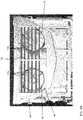
FIGS. 3-4 , an example of thefront grill 62 is shown in more detail. As illustrated, thefront grill 62 is shown having a generally rectangular or trapezoidal shape. In addition, thegrill 62 is slightly curved from front to back, so as to wrap around the front face of theTRU 34 as shown. However, it should be understood that agrill 62 having any shape and configuration is contemplated herein. - The
grill 62 includes one ormore louver members 72 arranged in an overlapping relationship with thesurround assembly 64. Thelouver members 72 may be made from any suitable material including but not limited to plastic and metal for example. In addition, in an embodiment, a noise deadening material 74 (seeFIG. 3B ), for example foam, may be mounted to a surface of thelouver members 72 generally adjacent thecentral opening 66. In the Figures, thegrill 62 includes a plurality of horizontally disposed and vertically spacedlouver members 72. The plurality oflouver members 72 may be substantially identical, or alternatively, may vary, such as based on the position of thelouver members 72 relative to thesurround assembly 64 for example. The one ormore louver members 72 may extend across a full width of thecentral opening 66 of thesurround assembly 64. However, in other arrangements, such as where the condenser unit (not shown) has two air movement devices (i.e. condenser fans) 71, at least a portion of thegrill 62 may include acentral support 76 and two distinct sets oflouver members 72. As shown, a first set oflouver members 72a extends from thecentral support 76 in a first direction and a second set oflouver members 72b extends from thecentral support 76 in a second, opposite direction. Together, the first and second set oflouver members central opening 66 of thesurround assembly 64. In that case, thecentral support 76 may be integrally formed with, or alternatively, may be separate from thesurround assembly 64. - Although in the Figures the first and second sets of
louver members central support 76, in other arrangements a configuration of the sets oflouver members louver members 72 arranged to span thecentral opening 66 of thesurround assembly 64. - The one or
more louver members 72 of thegrill 62 can be movable between a first position (FIGS. 3A ,3B ) and a second position (FIGS. 4A ,4B ). For example, the one ormore louver members 72 may be pivotally mounted such that each of thelouver members 72 is configured to rotate about a respective axis X, out of a plane of thesurround assembly 64, between the first position and the second position. However, other movement of thelouver members 72 is also possible. Because the plurality ofopenings 68 are defined between verticallyadjacent louver members 72, the height of eachopening 68, and therefore the cross-sectional area of eachopening 68, will vary as thelouver members 72 transition between the first position and the second position. The plurality ofopenings 68 may be considered to define a condenser inlet area arranged in fluid communication with thecentral opening 66. Accordingly, the condenser inlet area is variable by adjusting the position of thelouver members 72. - The one or
more louver members 72 can be oriented substantially perpendicular to thesurround assembly 64, and parallel to rotational axis of the condenser fans in the first position. Accordingly, when the one ormore louver members 72 are in the first position, the size of theopenings 68 defined there between is configured to maximize the air flow through thecentral opening 66 to anadjacent condenser fan 71. It should be understood that maximum cross-sectional area defined by theopenings 68 is dependent on the total number oflouver members 72 and the thickness of thelouver members 72. - In the second position, the one or
more louver members 72 are oriented at a non-perpendicular angle relative to thesurround assembly 64. The one ormore louver members 72 may be oriented substantially parallel to thesurround assembly 64 and perpendicular to the axis of thecondenser fans 71 when in the second position. Depending on the spacing of thelouver members 72, when in the second position, the one ormore louver members 72 may substantially seal the plurality ofopenings 68 to prevent a fluid flow through thecentral opening 66 to thecondenser fans 71. However, alternatively, in the second position, between about 10%-20% of the cross-sectional area of thecentral opening 66 may be exposed through theopenings 68 defined by thelouver members 72. - It should be understood that the first and second positions described herein are intended as an example only, and any orientation of the
louver members 72 may be defined as the first and second position. Further, it should be understood that the plurality oflouver members 72 may be arranged at any intermediate position between the first position and the second position. - With reference now to
FIG. 5 , theTRU 34 additionally includes acontrol system 80 including one ormore actuation mechanisms 82, such as an electrical motor or actuator for example, for moving thelouver members 72 between the first position and the second position. Power to operate the one ormore actuation mechanisms 82 may be supplied from another portion of thetrailer 20, such as a generator, illustrated schematically at 84. The plurality oflouver members 72 of thegrill 62, or alternatively, the plurality oflouver members 72 within a set may be connected to asingle actuation mechanism 82. As a result, theactuation mechanism 82 is operable to move each of the plurality oflouver members 72 about a respective axis X, in unison. Alternatively, theTRU 34 may include a plurality ofactuation mechanisms 82, such that the position of thelouver members 72 are adjusted in groups, or alternatively, individually. Accordingly, the positon of the plurality of thelouver members 72 may be adjusted non-uniformly. - The
control system 80 further includes acontroller 86 operably coupled to the one ormore actuation mechanisms 82. Thecontroller 86 may generate and send a command to anactuation mechanism 82 indicating a desired movement and/or location of thelouver members 72 associated therewith. Thecontroller 86 may be the same controller used to control operation of the refrigeration system, or alternatively, may be different. The controller may be configured to adjust the position of thelouver members 72 in response to a cooling demand of theTRU 34. For example, in high speed operation, when maximum cooling capacity of theTRU 34 is needed, thelouver members 72 may be rotated to the first, fully open position, to maximize the airflow provided to the condenser unit. Maximizing the cross-sectional area of theopenings 68 optimizes the cooling performance of theTRU 34. Similarly, during lower speed operation, thelouver members 72 may be rotated towards the second position to reduce the cross-sectional area of theopenings 68 and therefore the air flow provided to thecondenser fans 71. By reducing the size of theopenings 68, the noise generated by the air flow is reduced. - One or more sensors S may be associated with the
grill 62 or thesurround assembly 64 to monitor an actual position of thelouver members 72. The sensor information may be communicated to thecontroller 86 where it is compared with the commanded position of thelouver members 72, for example to determine an error value. Where the error value exceeds a predetermined threshold, thecontroller 86 may issue a corrected command intended to compensate for the discrepancy between the actual and commanded position. - A
TRU 34 as illustrated and described herein has a reduced noise output compared to existing systems. Further, thegrill 62 may be adapted for use with existing systems without having to adjust the position of thecondenser fans 71. - All of the component assemblies which define the outer cover of the refrigeration unit are mounted to the various structural components. In the Figures the TRU includes a curbside front door and a roadside front door. In their closed positions, the curbside front door and the roadside front door cover inner structural components of the unit as well as some of the refrigeration unit itself. These TRU additionally includes a curbside outer door and a roadside outer door. Each of the doors forming the lower portion of the cover are made from a tough, light weight composite material designed to resist rust, denting, warping, fading, or peeling of their outer finish.
- In the Figures the front doors are vertically hinged at their respective outer edges to provide a large access opening at the front of the unit. The side doors are vertically hinged at their rear edges such that the pivot open from front to back. Latches are provided for latching and unlatching the front roadside door and the side roadside door, respectively.
- Aspects of the embodiments are described herein with reference to flowchart illustrations, schematics, and/or block diagrams of methods, apparatus, and/or systems according to embodiments. Further, the descriptions of the various embodiments have been presented for purposes of illustration but are not intended to be exhaustive or limited to the embodiments disclosed. Many modifications and variations will be apparent to those of ordinary skill in the art without departing from the scope of the invention as defined by the claims. The terminology used herein was chosen to best explain the principles of the embodiments, the practical application or technical improvement over technologies found in the marketplace, or to enable others of ordinary skill in the art to understand the embodiments disclosed herein.
- The terminology used herein is for describing particular embodiments only and is not intended to be limiting. As used herein, the singular forms "a", "an" and "the" are intended to include the plural forms as well, unless the context clearly indicates otherwise. It will be further understood that the terms "comprises" and/or "comprising," when used in this specification, specify the presence of stated features, integers, steps, operations, elements, and/or components, but do not preclude the presence or addition of one more other features, integers, steps, operations, element components, and/or groups thereof.
- While the preferred embodiment has been described, it will be understood that those skilled in the art, both now and in the future, may make various improvements and enhancements which fall within the scope of the claims which follow. These claims should be construed to maintain the proper protection.
Claims (15)
- A cover assembly of a transport refrigeration unit comprising:a surround assembly having a central opening; anda grill positionable in overlapping relationship with the central opening, wherein the grill includes a plurality of louver members and a plurality of openings are defined between the plurality of louver members, the plurality of openings being arranged in fluid communication with the central opening;wherein the plurality of openings define an inlet area and the inlet area is variable.
- The cover assembly of claim 1, wherein the plurality of louver members are movable between a first position and a second position.
- The cover assembly of claim 2, wherein each of the plurality of louver members is rotatable about a respective axis between the first position and the second position.
- The cover assembly of either claim 2 or claim 3, wherein the inlet area is maximized when the plurality of louver members are in the first position.
- The cover assembly of claim 4, wherein the plurality of louver members extend generally perpendicular to a surface of the surround assembly when in the first position.
- The cover assembly of any of claims 2-5, wherein the inlet area is minimized when the plurality of louver members are in the second position.
- The cover assembly of any of claims 2-6, wherein the plurality of louver members extend generally parallel to a surface of the surround assembly when in the first position.
- The cover assembly of any of claims 2-7, wherein the plurality of openings are fully sealed when the plurality of louver members are in the second position.
- The cover assembly of any of claims 2-8, wherein between about 10% and 20% of the central opening is arranged in fluid communication with the plurality of openings when the plurality of louver members are in the second position.
- The cover assembly of any of claims 2-9, wherein the grill further comprises a central support and a first plurality of louver members extend from the central support in a first direction and a second plurality of louver members extend from the central support in a second direction.
- The cover assembly of any of claims 2-10, further comprising a control system including:an actuation mechanism coupled to at least one of the plurality of louver members; anda controller operably coupled to the actuation mechanism, wherein the controller communicates a movement command associated with the at least one of the plurality of louver members to the actuation mechanism.
- A transport refrigeration unit comprising:a condenser heat exchanger; anda cover assembly in overlying relationship with the condenser heat exchanger, wherein the cover assembly defines an inlet area through which air is provided to the condenser heat exchanger, wherein the inlet area is variable,optionally wherein the cover assembly is as defined in any preceding claim.
- The transport refrigeration unit of claim 12, wherein the inlet area is variable in response to a demand of the transport refrigeration unit.
- A method of operating a transport refrigeration system comprising:providing a surround assembly having a central opening;providing a grill in overlapping relationship with the central opening, the grill including a plurality of louver members that define an inlet area; andvarying the inlet area of the grill based on a demand of the transport refrigeration system;the method optionally comprising using a cover assembly as defined in any of claims 1 to 11.
- The method of claim 14, wherein varying the inlet area of the grill further comprises moving the plurality of louver members toward an open position to increase the inlet area and an airflow provided to the transport refrigeration unit in response to an increase in demand; and/or wherein varying the inlet area of the grill further comprises moving the plurality of louver members toward a closed position to decrease the inlet area and an airflow provided to the transport refrigeration unit in response to a decrease in demand.
Priority Applications (3)
| Application Number | Priority Date | Filing Date | Title |
|---|---|---|---|
| EP19305322.0A EP3711985B1 (en) | 2019-03-18 | 2019-03-18 | Grill for transport refrigeration unit |
| US16/819,429 US20200298671A1 (en) | 2019-03-18 | 2020-03-16 | Grill for transport refrigeration unit |
| CN202010186302.8A CN111703359B (en) | 2019-03-18 | 2020-03-17 | Grille for transport refrigeration unit |
Applications Claiming Priority (1)
| Application Number | Priority Date | Filing Date | Title |
|---|---|---|---|
| EP19305322.0A EP3711985B1 (en) | 2019-03-18 | 2019-03-18 | Grill for transport refrigeration unit |
Publications (2)
| Publication Number | Publication Date |
|---|---|
| EP3711985A1 true EP3711985A1 (en) | 2020-09-23 |
| EP3711985B1 EP3711985B1 (en) | 2023-05-10 |
Family
ID=66001145
Family Applications (1)
| Application Number | Title | Priority Date | Filing Date |
|---|---|---|---|
| EP19305322.0A Active EP3711985B1 (en) | 2019-03-18 | 2019-03-18 | Grill for transport refrigeration unit |
Country Status (3)
| Country | Link |
|---|---|
| US (1) | US20200298671A1 (en) |
| EP (1) | EP3711985B1 (en) |
| CN (1) | CN111703359B (en) |
Families Citing this family (3)
| Publication number | Priority date | Publication date | Assignee | Title |
|---|---|---|---|---|
| USD1065269S1 (en) * | 2019-11-18 | 2025-03-04 | Marmon Foodservice Technologies, Inc. | Grate for a refrigeration appliance |
| USD1067280S1 (en) * | 2019-12-11 | 2025-03-18 | Marmon Foodservice Technologies, Inc. | Grate for a refrigeration appliance |
| US20220149700A1 (en) * | 2020-11-06 | 2022-05-12 | Stewart & Stevenson Llc | Multi-fan mobile gas generator cooling system |
Citations (10)
| Publication number | Priority date | Publication date | Assignee | Title |
|---|---|---|---|---|
| US4567734A (en) * | 1984-08-31 | 1986-02-04 | Danhard, Inc. | Air deflector-air conditioner condenser integrated unit |
| US5317880A (en) * | 1992-04-20 | 1994-06-07 | Spears Dan E | Auxiliary braking and cooling device |
| US20060095178A1 (en) * | 2004-10-29 | 2006-05-04 | Freightliner Llc | Controlling the flow of air through at least one vehicle opening at a front portion of the vehicle |
| US20110048691A1 (en) * | 2009-08-27 | 2011-03-03 | Hyundai Motor Company | Fail-safe air flap control apparatus for vehicle |
| KR101240727B1 (en) * | 2011-08-30 | 2013-03-07 | 쌍용자동차 주식회사 | Ihvasion air shutter for automobile |
| US20140170960A1 (en) * | 2011-07-21 | 2014-06-19 | Frederic Vacca | Hole Sealing Device For The Front Face Of A Motor Vehicle |
| US20140273806A1 (en) * | 2013-03-15 | 2014-09-18 | Srg Global , Inc. | Grille Shutter Assembly |
| KR20150071262A (en) * | 2013-12-18 | 2015-06-26 | 한라비스테온공조 주식회사 | Active Air Flap |
| EP2944552A1 (en) * | 2014-05-13 | 2015-11-18 | C.R.F. Società Consortile per Azioni | Air guiding device for a motor-vehicle |
| US20160207394A1 (en) * | 2013-09-09 | 2016-07-21 | Valeo Systemes Thermiques | Ventilation shut-off flap for automobile |
Family Cites Families (2)
| Publication number | Priority date | Publication date | Assignee | Title |
|---|---|---|---|---|
| US9746230B2 (en) * | 2006-02-24 | 2017-08-29 | Carrier Corporation | Flame retardant door for transport refrigeration unit |
| US7827816B2 (en) * | 2006-05-09 | 2010-11-09 | Carrier Corporation | Front cover for transport refrigeration unit |
-
2019
- 2019-03-18 EP EP19305322.0A patent/EP3711985B1/en active Active
-
2020
- 2020-03-16 US US16/819,429 patent/US20200298671A1/en not_active Abandoned
- 2020-03-17 CN CN202010186302.8A patent/CN111703359B/en active Active
Patent Citations (10)
| Publication number | Priority date | Publication date | Assignee | Title |
|---|---|---|---|---|
| US4567734A (en) * | 1984-08-31 | 1986-02-04 | Danhard, Inc. | Air deflector-air conditioner condenser integrated unit |
| US5317880A (en) * | 1992-04-20 | 1994-06-07 | Spears Dan E | Auxiliary braking and cooling device |
| US20060095178A1 (en) * | 2004-10-29 | 2006-05-04 | Freightliner Llc | Controlling the flow of air through at least one vehicle opening at a front portion of the vehicle |
| US20110048691A1 (en) * | 2009-08-27 | 2011-03-03 | Hyundai Motor Company | Fail-safe air flap control apparatus for vehicle |
| US20140170960A1 (en) * | 2011-07-21 | 2014-06-19 | Frederic Vacca | Hole Sealing Device For The Front Face Of A Motor Vehicle |
| KR101240727B1 (en) * | 2011-08-30 | 2013-03-07 | 쌍용자동차 주식회사 | Ihvasion air shutter for automobile |
| US20140273806A1 (en) * | 2013-03-15 | 2014-09-18 | Srg Global , Inc. | Grille Shutter Assembly |
| US20160207394A1 (en) * | 2013-09-09 | 2016-07-21 | Valeo Systemes Thermiques | Ventilation shut-off flap for automobile |
| KR20150071262A (en) * | 2013-12-18 | 2015-06-26 | 한라비스테온공조 주식회사 | Active Air Flap |
| EP2944552A1 (en) * | 2014-05-13 | 2015-11-18 | C.R.F. Società Consortile per Azioni | Air guiding device for a motor-vehicle |
Also Published As
| Publication number | Publication date |
|---|---|
| CN111703359A (en) | 2020-09-25 |
| US20200298671A1 (en) | 2020-09-24 |
| EP3711985B1 (en) | 2023-05-10 |
| CN111703359B (en) | 2024-06-18 |
Similar Documents
| Publication | Publication Date | Title |
|---|---|---|
| CN102575909B (en) | For the damper assemblies of transport refrigeration system, transport refrigeration unit and method thereof | |
| EP2176606B1 (en) | A system for cooling food or beverages | |
| US5324229A (en) | Two section economizer damper assembly providing improved air mixing | |
| EP3711985B1 (en) | Grill for transport refrigeration unit | |
| EP1642070B1 (en) | Refrigerator | |
| US20210262718A1 (en) | Refrigerator with duct system to provide cold air from a freezer evaporator to an ice maker | |
| US7043926B2 (en) | Cargo area grocery chiller | |
| US6669555B2 (en) | Nozzle cover | |
| EP2015949B1 (en) | Transport refrigeration unit with a front cover | |
| EP3339068B1 (en) | Systems and methods of dynamic airflow control within an internal space | |
| WO2017147299A1 (en) | Active system for improved temperature control and air mixing inside refrigerated truck boxes, trailers and intermodal containers | |
| EP3261866B1 (en) | Transport refrigeration unit | |
| US20100218531A1 (en) | Grille surround assembly for transport refrigeration unit | |
| CN115540475B (en) | A refrigerator-air conditioner integrated unit, a refrigeration control system, and a refrigeration control method. | |
| JP6724802B2 (en) | Temperature control storage device | |
| JP2017072314A (en) | Air conditioned space inclusive facility, freezing refrigerator, freezing refrigerator device and freezing refrigerator warehouse | |
| US9746230B2 (en) | Flame retardant door for transport refrigeration unit | |
| US20120321490A1 (en) | Convertible and Compact Refrigeration System | |
| EP2838744B1 (en) | Flame retardant door for transport refrigeration unit | |
| JPH06234321A (en) | Air conditioner for vehicle | |
| CN209558765U (en) | Air supply device and refrigerator | |
| JP3510571B2 (en) | Bus vehicle air conditioner | |
| JP2006248337A (en) | Vehicle roof mounted air conditioner | |
| JPH07257166A (en) | Air conditioner | |
| HK1172947B (en) | Damper apparatus for transport refrigeration system, transport refrigeration unit, and methods for same |
Legal Events
| Date | Code | Title | Description |
|---|---|---|---|
| PUAI | Public reference made under article 153(3) epc to a published international application that has entered the european phase |
Free format text: ORIGINAL CODE: 0009012 |
|
| STAA | Information on the status of an ep patent application or granted ep patent |
Free format text: STATUS: THE APPLICATION HAS BEEN PUBLISHED |
|
| AK | Designated contracting states |
Kind code of ref document: A1 Designated state(s): AL AT BE BG CH CY CZ DE DK EE ES FI FR GB GR HR HU IE IS IT LI LT LU LV MC MK MT NL NO PL PT RO RS SE SI SK SM TR |
|
| AX | Request for extension of the european patent |
Extension state: BA ME |
|
| STAA | Information on the status of an ep patent application or granted ep patent |
Free format text: STATUS: REQUEST FOR EXAMINATION WAS MADE |
|
| 17P | Request for examination filed |
Effective date: 20210322 |
|
| RBV | Designated contracting states (corrected) |
Designated state(s): AL AT BE BG CH CY CZ DE DK EE ES FI FR GB GR HR HU IE IS IT LI LT LU LV MC MK MT NL NO PL PT RO RS SE SI SK SM TR |
|
| GRAP | Despatch of communication of intention to grant a patent |
Free format text: ORIGINAL CODE: EPIDOSNIGR1 |
|
| STAA | Information on the status of an ep patent application or granted ep patent |
Free format text: STATUS: GRANT OF PATENT IS INTENDED |
|
| INTG | Intention to grant announced |
Effective date: 20221125 |
|
| GRAS | Grant fee paid |
Free format text: ORIGINAL CODE: EPIDOSNIGR3 |
|
| GRAA | (expected) grant |
Free format text: ORIGINAL CODE: 0009210 |
|
| STAA | Information on the status of an ep patent application or granted ep patent |
Free format text: STATUS: THE PATENT HAS BEEN GRANTED |
|
| AK | Designated contracting states |
Kind code of ref document: B1 Designated state(s): AL AT BE BG CH CY CZ DE DK EE ES FI FR GB GR HR HU IE IS IT LI LT LU LV MC MK MT NL NO PL PT RO RS SE SI SK SM TR |
|
| REG | Reference to a national code |
Ref country code: GB Ref legal event code: FG4D |
|
| REG | Reference to a national code |
Ref country code: AT Ref legal event code: REF Ref document number: 1566360 Country of ref document: AT Kind code of ref document: T Effective date: 20230515 Ref country code: CH Ref legal event code: EP |
|
| REG | Reference to a national code |
Ref country code: DE Ref legal event code: R096 Ref document number: 602019028699 Country of ref document: DE |
|
| REG | Reference to a national code |
Ref country code: IE Ref legal event code: FG4D |
|
| REG | Reference to a national code |
Ref country code: NL Ref legal event code: FP |
|
| REG | Reference to a national code |
Ref country code: LT Ref legal event code: MG9D |
|
| REG | Reference to a national code |
Ref country code: AT Ref legal event code: MK05 Ref document number: 1566360 Country of ref document: AT Kind code of ref document: T Effective date: 20230510 |
|
| PG25 | Lapsed in a contracting state [announced via postgrant information from national office to epo] |
Ref country code: SE Free format text: LAPSE BECAUSE OF FAILURE TO SUBMIT A TRANSLATION OF THE DESCRIPTION OR TO PAY THE FEE WITHIN THE PRESCRIBED TIME-LIMIT Effective date: 20230510 Ref country code: PT Free format text: LAPSE BECAUSE OF FAILURE TO SUBMIT A TRANSLATION OF THE DESCRIPTION OR TO PAY THE FEE WITHIN THE PRESCRIBED TIME-LIMIT Effective date: 20230911 Ref country code: NO Free format text: LAPSE BECAUSE OF FAILURE TO SUBMIT A TRANSLATION OF THE DESCRIPTION OR TO PAY THE FEE WITHIN THE PRESCRIBED TIME-LIMIT Effective date: 20230810 Ref country code: ES Free format text: LAPSE BECAUSE OF FAILURE TO SUBMIT A TRANSLATION OF THE DESCRIPTION OR TO PAY THE FEE WITHIN THE PRESCRIBED TIME-LIMIT Effective date: 20230510 Ref country code: AT Free format text: LAPSE BECAUSE OF FAILURE TO SUBMIT A TRANSLATION OF THE DESCRIPTION OR TO PAY THE FEE WITHIN THE PRESCRIBED TIME-LIMIT Effective date: 20230510 |
|
| PG25 | Lapsed in a contracting state [announced via postgrant information from national office to epo] |
Ref country code: RS Free format text: LAPSE BECAUSE OF FAILURE TO SUBMIT A TRANSLATION OF THE DESCRIPTION OR TO PAY THE FEE WITHIN THE PRESCRIBED TIME-LIMIT Effective date: 20230510 Ref country code: PL Free format text: LAPSE BECAUSE OF FAILURE TO SUBMIT A TRANSLATION OF THE DESCRIPTION OR TO PAY THE FEE WITHIN THE PRESCRIBED TIME-LIMIT Effective date: 20230510 Ref country code: LV Free format text: LAPSE BECAUSE OF FAILURE TO SUBMIT A TRANSLATION OF THE DESCRIPTION OR TO PAY THE FEE WITHIN THE PRESCRIBED TIME-LIMIT Effective date: 20230510 Ref country code: LT Free format text: LAPSE BECAUSE OF FAILURE TO SUBMIT A TRANSLATION OF THE DESCRIPTION OR TO PAY THE FEE WITHIN THE PRESCRIBED TIME-LIMIT Effective date: 20230510 Ref country code: IS Free format text: LAPSE BECAUSE OF FAILURE TO SUBMIT A TRANSLATION OF THE DESCRIPTION OR TO PAY THE FEE WITHIN THE PRESCRIBED TIME-LIMIT Effective date: 20230910 Ref country code: HR Free format text: LAPSE BECAUSE OF FAILURE TO SUBMIT A TRANSLATION OF THE DESCRIPTION OR TO PAY THE FEE WITHIN THE PRESCRIBED TIME-LIMIT Effective date: 20230510 Ref country code: GR Free format text: LAPSE BECAUSE OF FAILURE TO SUBMIT A TRANSLATION OF THE DESCRIPTION OR TO PAY THE FEE WITHIN THE PRESCRIBED TIME-LIMIT Effective date: 20230811 |
|
| PG25 | Lapsed in a contracting state [announced via postgrant information from national office to epo] |
Ref country code: FI Free format text: LAPSE BECAUSE OF FAILURE TO SUBMIT A TRANSLATION OF THE DESCRIPTION OR TO PAY THE FEE WITHIN THE PRESCRIBED TIME-LIMIT Effective date: 20230510 |
|
| PG25 | Lapsed in a contracting state [announced via postgrant information from national office to epo] |
Ref country code: SK Free format text: LAPSE BECAUSE OF FAILURE TO SUBMIT A TRANSLATION OF THE DESCRIPTION OR TO PAY THE FEE WITHIN THE PRESCRIBED TIME-LIMIT Effective date: 20230510 |
|
| PG25 | Lapsed in a contracting state [announced via postgrant information from national office to epo] |
Ref country code: SM Free format text: LAPSE BECAUSE OF FAILURE TO SUBMIT A TRANSLATION OF THE DESCRIPTION OR TO PAY THE FEE WITHIN THE PRESCRIBED TIME-LIMIT Effective date: 20230510 Ref country code: SK Free format text: LAPSE BECAUSE OF FAILURE TO SUBMIT A TRANSLATION OF THE DESCRIPTION OR TO PAY THE FEE WITHIN THE PRESCRIBED TIME-LIMIT Effective date: 20230510 Ref country code: RO Free format text: LAPSE BECAUSE OF FAILURE TO SUBMIT A TRANSLATION OF THE DESCRIPTION OR TO PAY THE FEE WITHIN THE PRESCRIBED TIME-LIMIT Effective date: 20230510 Ref country code: EE Free format text: LAPSE BECAUSE OF FAILURE TO SUBMIT A TRANSLATION OF THE DESCRIPTION OR TO PAY THE FEE WITHIN THE PRESCRIBED TIME-LIMIT Effective date: 20230510 Ref country code: DK Free format text: LAPSE BECAUSE OF FAILURE TO SUBMIT A TRANSLATION OF THE DESCRIPTION OR TO PAY THE FEE WITHIN THE PRESCRIBED TIME-LIMIT Effective date: 20230510 Ref country code: CZ Free format text: LAPSE BECAUSE OF FAILURE TO SUBMIT A TRANSLATION OF THE DESCRIPTION OR TO PAY THE FEE WITHIN THE PRESCRIBED TIME-LIMIT Effective date: 20230510 |
|
| REG | Reference to a national code |
Ref country code: DE Ref legal event code: R097 Ref document number: 602019028699 Country of ref document: DE |
|
| PLBE | No opposition filed within time limit |
Free format text: ORIGINAL CODE: 0009261 |
|
| STAA | Information on the status of an ep patent application or granted ep patent |
Free format text: STATUS: NO OPPOSITION FILED WITHIN TIME LIMIT |
|
| 26N | No opposition filed |
Effective date: 20240213 |
|
| PG25 | Lapsed in a contracting state [announced via postgrant information from national office to epo] |
Ref country code: SI Free format text: LAPSE BECAUSE OF FAILURE TO SUBMIT A TRANSLATION OF THE DESCRIPTION OR TO PAY THE FEE WITHIN THE PRESCRIBED TIME-LIMIT Effective date: 20230510 |
|
| PG25 | Lapsed in a contracting state [announced via postgrant information from national office to epo] |
Ref country code: SI Free format text: LAPSE BECAUSE OF FAILURE TO SUBMIT A TRANSLATION OF THE DESCRIPTION OR TO PAY THE FEE WITHIN THE PRESCRIBED TIME-LIMIT Effective date: 20230510 Ref country code: IT Free format text: LAPSE BECAUSE OF FAILURE TO SUBMIT A TRANSLATION OF THE DESCRIPTION OR TO PAY THE FEE WITHIN THE PRESCRIBED TIME-LIMIT Effective date: 20230510 |
|
| REG | Reference to a national code |
Ref country code: CH Ref legal event code: PL |
|
| PG25 | Lapsed in a contracting state [announced via postgrant information from national office to epo] |
Ref country code: BG Free format text: LAPSE BECAUSE OF FAILURE TO SUBMIT A TRANSLATION OF THE DESCRIPTION OR TO PAY THE FEE WITHIN THE PRESCRIBED TIME-LIMIT Effective date: 20230510 |
|
| PG25 | Lapsed in a contracting state [announced via postgrant information from national office to epo] |
Ref country code: LU Free format text: LAPSE BECAUSE OF NON-PAYMENT OF DUE FEES Effective date: 20240318 |
|
| PG25 | Lapsed in a contracting state [announced via postgrant information from national office to epo] |
Ref country code: MC Free format text: LAPSE BECAUSE OF FAILURE TO SUBMIT A TRANSLATION OF THE DESCRIPTION OR TO PAY THE FEE WITHIN THE PRESCRIBED TIME-LIMIT Effective date: 20230510 |
|
| PG25 | Lapsed in a contracting state [announced via postgrant information from national office to epo] |
Ref country code: MC Free format text: LAPSE BECAUSE OF FAILURE TO SUBMIT A TRANSLATION OF THE DESCRIPTION OR TO PAY THE FEE WITHIN THE PRESCRIBED TIME-LIMIT Effective date: 20230510 Ref country code: LU Free format text: LAPSE BECAUSE OF NON-PAYMENT OF DUE FEES Effective date: 20240318 Ref country code: BG Free format text: LAPSE BECAUSE OF FAILURE TO SUBMIT A TRANSLATION OF THE DESCRIPTION OR TO PAY THE FEE WITHIN THE PRESCRIBED TIME-LIMIT Effective date: 20230510 |
|
| REG | Reference to a national code |
Ref country code: BE Ref legal event code: MM Effective date: 20240331 |
|
| PG25 | Lapsed in a contracting state [announced via postgrant information from national office to epo] |
Ref country code: BE Free format text: LAPSE BECAUSE OF NON-PAYMENT OF DUE FEES Effective date: 20240331 |
|
| PG25 | Lapsed in a contracting state [announced via postgrant information from national office to epo] |
Ref country code: IE Free format text: LAPSE BECAUSE OF NON-PAYMENT OF DUE FEES Effective date: 20240318 |
|
| PG25 | Lapsed in a contracting state [announced via postgrant information from national office to epo] |
Ref country code: IE Free format text: LAPSE BECAUSE OF NON-PAYMENT OF DUE FEES Effective date: 20240318 Ref country code: BE Free format text: LAPSE BECAUSE OF NON-PAYMENT OF DUE FEES Effective date: 20240331 Ref country code: CH Free format text: LAPSE BECAUSE OF NON-PAYMENT OF DUE FEES Effective date: 20240331 |
|
| PGFP | Annual fee paid to national office [announced via postgrant information from national office to epo] |
Ref country code: NL Payment date: 20250219 Year of fee payment: 7 |
|
| PGFP | Annual fee paid to national office [announced via postgrant information from national office to epo] |
Ref country code: DE Payment date: 20250218 Year of fee payment: 7 |
|
| PGFP | Annual fee paid to national office [announced via postgrant information from national office to epo] |
Ref country code: FR Payment date: 20250218 Year of fee payment: 7 |
|
| PGFP | Annual fee paid to national office [announced via postgrant information from national office to epo] |
Ref country code: GB Payment date: 20250221 Year of fee payment: 7 |
|
| PG25 | Lapsed in a contracting state [announced via postgrant information from national office to epo] |
Ref country code: CY Free format text: LAPSE BECAUSE OF FAILURE TO SUBMIT A TRANSLATION OF THE DESCRIPTION OR TO PAY THE FEE WITHIN THE PRESCRIBED TIME-LIMIT; INVALID AB INITIO Effective date: 20190318 |
|
| PG25 | Lapsed in a contracting state [announced via postgrant information from national office to epo] |
Ref country code: HU Free format text: LAPSE BECAUSE OF FAILURE TO SUBMIT A TRANSLATION OF THE DESCRIPTION OR TO PAY THE FEE WITHIN THE PRESCRIBED TIME-LIMIT; INVALID AB INITIO Effective date: 20190318 |
|
| PG25 | Lapsed in a contracting state [announced via postgrant information from national office to epo] |
Ref country code: TR Free format text: LAPSE BECAUSE OF FAILURE TO SUBMIT A TRANSLATION OF THE DESCRIPTION OR TO PAY THE FEE WITHIN THE PRESCRIBED TIME-LIMIT Effective date: 20230510 |