EP3711934B1 - Materiau composite et procede de realisation d'un tel materiau composite - Google Patents
Materiau composite et procede de realisation d'un tel materiau composite Download PDFInfo
- Publication number
- EP3711934B1 EP3711934B1 EP20164301.2A EP20164301A EP3711934B1 EP 3711934 B1 EP3711934 B1 EP 3711934B1 EP 20164301 A EP20164301 A EP 20164301A EP 3711934 B1 EP3711934 B1 EP 3711934B1
- Authority
- EP
- European Patent Office
- Prior art keywords
- composite material
- layers
- heat exchanger
- resin
- fabric made
- Prior art date
- Legal status (The legal status is an assumption and is not a legal conclusion. Google has not performed a legal analysis and makes no representation as to the accuracy of the status listed.)
- Active
Links
Images


Classifications
-
- B—PERFORMING OPERATIONS; TRANSPORTING
- B29—WORKING OF PLASTICS; WORKING OF SUBSTANCES IN A PLASTIC STATE IN GENERAL
- B29C—SHAPING OR JOINING OF PLASTICS; SHAPING OF MATERIAL IN A PLASTIC STATE, NOT OTHERWISE PROVIDED FOR; AFTER-TREATMENT OF THE SHAPED PRODUCTS, e.g. REPAIRING
- B29C70/00—Shaping composites, i.e. plastics material comprising reinforcements, fillers or preformed parts, e.g. inserts
- B29C70/04—Shaping composites, i.e. plastics material comprising reinforcements, fillers or preformed parts, e.g. inserts comprising reinforcements only, e.g. self-reinforcing plastics
- B29C70/28—Shaping operations therefor
- B29C70/40—Shaping or impregnating by compression not applied
- B29C70/42—Shaping or impregnating by compression not applied for producing articles of definite length, i.e. discrete articles
- B29C70/46—Shaping or impregnating by compression not applied for producing articles of definite length, i.e. discrete articles using matched moulds, e.g. for deforming sheet moulding compounds [SMC] or prepregs
- B29C70/48—Shaping or impregnating by compression not applied for producing articles of definite length, i.e. discrete articles using matched moulds, e.g. for deforming sheet moulding compounds [SMC] or prepregs and impregnating the reinforcements in the closed mould, e.g. resin transfer moulding [RTM], e.g. by vacuum
-
- B—PERFORMING OPERATIONS; TRANSPORTING
- B29—WORKING OF PLASTICS; WORKING OF SUBSTANCES IN A PLASTIC STATE IN GENERAL
- B29C—SHAPING OR JOINING OF PLASTICS; SHAPING OF MATERIAL IN A PLASTIC STATE, NOT OTHERWISE PROVIDED FOR; AFTER-TREATMENT OF THE SHAPED PRODUCTS, e.g. REPAIRING
- B29C70/00—Shaping composites, i.e. plastics material comprising reinforcements, fillers or preformed parts, e.g. inserts
- B29C70/04—Shaping composites, i.e. plastics material comprising reinforcements, fillers or preformed parts, e.g. inserts comprising reinforcements only, e.g. self-reinforcing plastics
- B29C70/28—Shaping operations therefor
- B29C70/54—Component parts, details or accessories; Auxiliary operations, e.g. feeding or storage of prepregs or SMC after impregnation or during ageing
- B29C70/545—Perforating, cutting or machining during or after moulding
-
- B—PERFORMING OPERATIONS; TRANSPORTING
- B29—WORKING OF PLASTICS; WORKING OF SUBSTANCES IN A PLASTIC STATE IN GENERAL
- B29D—PRODUCING PARTICULAR ARTICLES FROM PLASTICS OR FROM SUBSTANCES IN A PLASTIC STATE
- B29D99/00—Subject matter not provided for in other groups of this subclass
- B29D99/001—Producing wall or panel-like structures, e.g. for hulls, fuselages, or buildings
-
- F—MECHANICAL ENGINEERING; LIGHTING; HEATING; WEAPONS; BLASTING
- F02—COMBUSTION ENGINES; HOT-GAS OR COMBUSTION-PRODUCT ENGINE PLANTS
- F02C—GAS-TURBINE PLANTS; AIR INTAKES FOR JET-PROPULSION PLANTS; CONTROLLING FUEL SUPPLY IN AIR-BREATHING JET-PROPULSION PLANTS
- F02C7/00—Features, components parts, details or accessories, not provided for in, or of interest apart form groups F02C1/00 - F02C6/00; Air intakes for jet-propulsion plants
- F02C7/12—Cooling of plants
- F02C7/16—Cooling of plants characterised by cooling medium
- F02C7/18—Cooling of plants characterised by cooling medium the medium being gaseous, e.g. air
- F02C7/185—Cooling means for reducing the temperature of the cooling air or gas
-
- F—MECHANICAL ENGINEERING; LIGHTING; HEATING; WEAPONS; BLASTING
- F28—HEAT EXCHANGE IN GENERAL
- F28F—DETAILS OF HEAT-EXCHANGE AND HEAT-TRANSFER APPARATUS, OF GENERAL APPLICATION
- F28F21/00—Constructions of heat-exchange apparatus characterised by the selection of particular materials
- F28F21/06—Constructions of heat-exchange apparatus characterised by the selection of particular materials of plastics material
-
- F—MECHANICAL ENGINEERING; LIGHTING; HEATING; WEAPONS; BLASTING
- F28—HEAT EXCHANGE IN GENERAL
- F28F—DETAILS OF HEAT-EXCHANGE AND HEAT-TRANSFER APPARATUS, OF GENERAL APPLICATION
- F28F21/00—Constructions of heat-exchange apparatus characterised by the selection of particular materials
- F28F21/06—Constructions of heat-exchange apparatus characterised by the selection of particular materials of plastics material
- F28F21/065—Constructions of heat-exchange apparatus characterised by the selection of particular materials of plastics material the heat-exchange apparatus employing plate-like or laminated conduits
-
- F—MECHANICAL ENGINEERING; LIGHTING; HEATING; WEAPONS; BLASTING
- F28—HEAT EXCHANGE IN GENERAL
- F28F—DETAILS OF HEAT-EXCHANGE AND HEAT-TRANSFER APPARATUS, OF GENERAL APPLICATION
- F28F3/00—Plate-like or laminated elements; Assemblies of plate-like or laminated elements
-
- B—PERFORMING OPERATIONS; TRANSPORTING
- B29—WORKING OF PLASTICS; WORKING OF SUBSTANCES IN A PLASTIC STATE IN GENERAL
- B29L—INDEXING SCHEME ASSOCIATED WITH SUBCLASS B29C, RELATING TO PARTICULAR ARTICLES
- B29L2031/00—Other particular articles
- B29L2031/18—Heat-exchangers or parts thereof
-
- B—PERFORMING OPERATIONS; TRANSPORTING
- B29—WORKING OF PLASTICS; WORKING OF SUBSTANCES IN A PLASTIC STATE IN GENERAL
- B29L—INDEXING SCHEME ASSOCIATED WITH SUBCLASS B29C, RELATING TO PARTICULAR ARTICLES
- B29L2031/00—Other particular articles
- B29L2031/30—Vehicles, e.g. ships or aircraft, or body parts thereof
- B29L2031/3076—Aircrafts
-
- F—MECHANICAL ENGINEERING; LIGHTING; HEATING; WEAPONS; BLASTING
- F28—HEAT EXCHANGE IN GENERAL
- F28F—DETAILS OF HEAT-EXCHANGE AND HEAT-TRANSFER APPARATUS, OF GENERAL APPLICATION
- F28F2255/00—Heat exchanger elements made of materials having special features or resulting from particular manufacturing processes
- F28F2255/06—Heat exchanger elements made of materials having special features or resulting from particular manufacturing processes composite, e.g. polymers with fillers or fibres
-
- Y—GENERAL TAGGING OF NEW TECHNOLOGICAL DEVELOPMENTS; GENERAL TAGGING OF CROSS-SECTIONAL TECHNOLOGIES SPANNING OVER SEVERAL SECTIONS OF THE IPC; TECHNICAL SUBJECTS COVERED BY FORMER USPC CROSS-REFERENCE ART COLLECTIONS [XRACs] AND DIGESTS
- Y02—TECHNOLOGIES OR APPLICATIONS FOR MITIGATION OR ADAPTATION AGAINST CLIMATE CHANGE
- Y02T—CLIMATE CHANGE MITIGATION TECHNOLOGIES RELATED TO TRANSPORTATION
- Y02T50/00—Aeronautics or air transport
- Y02T50/60—Efficient propulsion technologies, e.g. for aircraft
Definitions
- the present invention lies in the field of heat exchange at the level of aircraft engines, and more generally any type of hot source. It relates to a composite material and a process for producing such a composite material. The invention relates more particularly to a method for producing a heat exchanger cover and a heat exchanger cover.
- a heat exchanger cowl is arranged on the engine, for example of an aircraft, and is intended to evacuate the calories emitted by the aircraft engine. It is located above the engine and is subjected to a temperature close to 300°C continuously. Due to the high temperature to which it is subjected, the heat exchanger cover is now made of titanium.
- the document CN 207 496 787 describes an engine cover with vents.
- titanium in the manufacture of a heat exchanger cover is advantageous because titanium has good mechanical properties in terms of temperature resistance.
- a titanium heat exchanger cover has a high material and manufacturing cost.
- metal parts are generally known to be fragile in fatigue, especially in an environment exposed to strong vibrations.
- the documents CN 103 921 453 and DE 20 2007 015789 describe composite materials of the prior art.
- the invention aims to overcome all or part of the problems mentioned above by proposing a composite material and a process for producing such a composite material having good mechanical strength and suitable for high temperatures.
- the subject of the invention is a process for producing a composite material for a heat exchanger cover, according to the characteristics of claim 1.
- the injected resin is a cyanate-ester resin.
- the step of superimposing the plurality of layers of fabric made up of basalt fibers comprises a step of inserting at least one layer of fabric made up of carbon fibers between the layers of fabric made up of basalt.
- the invention also relates to a method for producing a heat exchanger cover, comprising the steps of the method for producing a composite material and comprising, after the demolding step, a step of cutting out openings in the composite material.
- the method for producing a cover comprises, before or after the step of cutting out the openings, a step of machining the composite material to give it the shape of the heat exchanger cover.
- the resin constituting the matrix is a cyanate-ester resin.
- the reinforcement composed of a plurality of layers of fabric composed of basalt fibers is also composed of at least one layer of fabric composed of carbon fibers.
- the invention also relates to a heat exchanger cover, comprising a composite material as mentioned above, and openings cut out of the composite material.
- the figure 1 illustrates the steps of the method for producing a composite material 10 according to the invention.
- the method for producing a composite material 10 according to the invention is particularly suitable for a heat exchanger cover 20, as explained below.
- the composite material 10 obtained can be used in any other context, advantageously in a temperature range between 250 and 300°C.
- the method for producing the composite material 10 according to the invention comprises the following steps carried out successively. First of all, it includes a step 101 of superimposing a plurality of layers of fabric composed of basalt fibers 11.
- the reinforcement comprises only layers of fabric composed of basalt fibers 11 for its low cost and a very largely sufficient resistance to temperature.
- a reinforcement comprising in addition layers of fabric composed of carbon fibers 13 will make it possible to increase the mechanical capacities of the material at iso-thickness if necessary.
- Basalt fiber is made from a rock of volcanic origin. Its manufacture is relatively complex. Indeed, it is necessary to melt the crushed volcanic rock to extract the fibers. Basalt fiber has particularly interesting physico-mechanical properties since it is fire resistant. It is also three to four times less expensive than carbon, silica or ceramic fibre. A basalt fiber fabric resists a flame of around 1200 to 1400°C depending on its composition and purity.
- the method then comprises a step 103 of arranging the plurality of compacted layers in a mould. It is a rigid mold and closed, in the shape of the piece that you want to make. If necessary, the reinforcement can be wedged into the mould.
- the next step is a step 104 of injection of a resin 12.
- the step 104 of injection is molding by resin transfer, also called low-pressure injection into the mold of a resin 12 heated until it has of the compatible viscosity of the injection process, until the filling of the mould.
- the resin 12 is therefore heated prior to the injection step 104, typically to 100-120°C.
- the mould, for its part, is also heated beforehand, in order to avoid the cooling of the resin 12 during its transfer into the mould.
- the injection pressure is of the order of a few bars, for example 5 or 6 bars, and does not exceed 15 bars.
- the resin 12 thus injected fills the space left free in the mold.
- the injection of resin 12 takes place through the fibrous reinforcement already in place in the mould.
- This injection is also known by the abbreviation RTM for its Anglo-Saxon acronym “Resine Transfer Molding”.
- the injection can take place at one point or several points of the mould.
- This type of injection uses dry reinforcements, that is to say that the addition of resin 12 is done in the final phase of the process, once the reinforcement of the part has been built. There is no need to use pre-impregnated reinforcing fibers.
- Another advantage is that it makes it possible to produce a part almost to its final definition, with precise dimensions and presenting a good surface finish over the entire surface of the part.
- the injection step 104 is followed by a step 105 of heating the mold to form the composite material 10.
- the mold is heated to a temperature of approximately 200° C., with a gradual rise in temperature. If the firing is too rapid or if certain stages of firing are not respected, the part will not have the desired mechanical properties at the desired temperatures.
- the method according to the invention comprises a step 106 of demolding the composite material 10 thus obtained.
- the mold is opened and the composite material 10 is unmolded.
- the step 106 of demolding can be followed by a step 108 of stripping the composite material 10.
- step 110 of post-curing out of the mold in order to guarantee the final thermal and mechanical properties.
- This step 110 requires special environmental precautions and temperature ranges so as not to risk prematurely oxidizing the organic resin if it is subjected to the oxygen in the air during the rise in temperature. Thus, it is recommended to carry out the post-curing step 110 under vacuum to avoid the presence of oxygen which would react with the carbon present in the resin and would participate in burning the resin.
- the method according to the invention makes it possible to carry out the post-curing step 110 in an ambient environment, and makes it possible to obtain a composite material resistant to temperatures of the order of 270-280°C. Performing step 110 in an ambient environment simplifies the method.
- resin Unlike basalt fiber, resin generally does not withstand high temperature environments.
- the injected resin 12 is a cyanate-ester resin.
- This resin has good thermal stability at elevated temperatures.
- the cyanate-ester resin exhibits an exothermic character during the polymerization process. It is therefore imperative to control the curing cycle during step 104 of injection by RTM so as not to roast the resin 12 during step 105 of heating.
- the step 101 of superimposing the plurality of layers of fabric made up of basalt fibers only comprises a step 107 of inserting at least one layer of fabric made up of carbon fibers 13 between the layers of fabric made up of basalt fibers 11.
- Carbon fiber has low density (between 1.7 and 1.9), and also has good temperature resistance.
- the insertion of at least one layer of fabric composed of carbon fibers in the layers of fabric composed solely of basalt fibers makes it possible to increase the mechanical capacity of the composite material obtained.
- the method presented makes it possible to produce a composite material 10 resistant to temperatures of the order of 250-300°C.
- the composite material 10 is less sensitive to stresses of the fatigue type than metal and therefore makes it possible to consider less replacement of parts during its operational use.
- the process for producing the composite material 10 can serve as a basis for a process for producing a heat exchanger cover 20 intended to evacuate the heat produced by an engine.
- the picture 2 illustrates the steps of such a method for producing a heat exchanger cover 20 according to the invention.
- the method for producing a heat exchanger cover 20 comprises the steps of the method for producing a composite material 10 as described previously.
- the mold has the shape of the cover 20.
- the result, after step 106 of demoulding, is a cover 20 of precise dimensions, presenting a good surface condition over the entire surface of the part and almost to its definition. final.
- it comprises, after the step 106 of demolding, a step 108 of cutting openings 21 in the composite material 10.
- the openings 21 allow the circulation of air through the heat exchanger cover 20.
- the heat exchanger cover 20 thus obtained is lighter than its metal counterpart.
- the gain in mass is of the order of 20%.
- the manufacturing cost of such a cover is lower than that of a titanium cover obtained by forming.
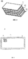
- the picture 3 schematically represents a composite material 10 according to the invention.
- the composite material 10 comprises a reinforcement composed of a plurality of layers of fabric composed of basalt fibers 11 arranged on top of each other and compacted between them, and a matrix impregnating the reinforcement, consisting of a resin 12 configured to resist temperatures of at least 250°C.
- the reinforcement of the composite material 10 composed of a plurality of layers of fabric composed of basalt fibers is composed, in addition to the layers of fabric composed of basalt fibers, of at least one layer of fabric composed of carbon fibers 13.
- the resin 12 constituting the matrix is a cyanate-ester resin, compatible with high temperatures of the order of 250 to 300°C.
- the figure 4 schematically represents a front view of a heat exchanger cover 20 according to the invention.
- the heat exchanger cover 20 is made of the composite material 10 previously described. It further comprises openings 21 cut out of the composite material 10, to allow the evacuation of the calories emitted by the engine.
- the cover represented measures approximately 500 mm long and 300 mm wide, with a thickness of the order of a few millimeters, for example 3 to 5 mm.
- the cover can also include perforations 22, in order to allow the fixing of the cover on the engine.
- the figure 5 schematically represents an isometric view of a heat exchanger hood 20 according to the invention.
- the shape of the cover is given by the shape of the mold used during the process for producing the composite material 10.
- the invention has been described in the example of a heat exchanger cowl intended for use on an engine. It should be noted that the invention applies to any part, of any shape, usable in an environment of high temperatures around 250-300°C.
Landscapes
- Engineering & Computer Science (AREA)
- Mechanical Engineering (AREA)
- General Engineering & Computer Science (AREA)
- Chemical & Material Sciences (AREA)
- Thermal Sciences (AREA)
- Physics & Mathematics (AREA)
- Combustion & Propulsion (AREA)
- Composite Materials (AREA)
- Structural Engineering (AREA)
- Civil Engineering (AREA)
- Architecture (AREA)
- Moulding By Coating Moulds (AREA)
- Reinforced Plastic Materials (AREA)
- Laminated Bodies (AREA)
Description
- La présente invention se situe dans le domaine de l'échange thermique au niveau des moteurs d'aéronef, et plus généralement tout type de source chaude. Elle concerne un matériau composite et un procédé de réalisation d'un tel matériau composite. L'invention concerne plus particulièrement un procédé de réalisation d'un capot échangeur thermique et un capot échangeur thermique.
- Un capot échangeur thermique est disposé sur le moteur, par exemple d'un avion, et est destiné à évacuer les calories émises par le moteur d'avion. Il est situé au-dessus du moteur et est soumis à une température proche de 300°C en continu. Du fait de la température élevée à laquelle il est soumis, le capot échangeur thermique est aujourd'hui fabriqué en titane. Le document
CN 207 496 787 décrit un capot moteur avec des ouïes. - L'utilisation du titane dans la fabrication d'un capot échangeur thermique est avantageuse car le titane présente de bonnes propriétés mécaniques en termes de résistance en température. Toutefois, un capot échangeur thermique en titane a un coût matière et de fabrication élevé. De plus, les pièces métalliques sont en général réputées être fragiles en fatigue, surtout dans un milieu exposé à de fortes vibrations. Les documents
CN 103 921 453 etDE 20 2007 015789 décrivent des matériaux composite de l'art antérieur. - L'utilisation de céramiques dont la tenue en température est, par essence, particulièrement adaptée, pourrait être envisagée mais leur manque de souplesse engendrerait des fissures et casses du capot.
- Les résines organiques traditionnelles sont connues pour ne pas supporter les températures élevées et paraissent difficilement envisageables pour l'application recherchée.
- L'invention vise à pallier tout ou partie des problèmes cités plus haut en proposant un matériau composite et un procédé de réalisation d'un tel matériau composite présentant une bonne résistance mécanique et adapté à des températures élevées.
- A cet effet, l'invention a pour objet un procédé de réalisation d'un matériau composite pour capot échangeur thermique, selon les caractéristiques de la revendication 1.
- Avantageusement, la résine injectée est une résine cyanate-ester.
- Selon l'invention, l'étape de superposition de la pluralité de couches de tissu composé de fibres de basalte comprend une étape d'insertion d'au moins une couche de tissu composé de fibres de carbone entre les couches de tissu composé de fibres de basalte.
- L'invention concerne aussi un procédé de réalisation d'un capot échangeur thermique, comprenant les étapes du procédé de réalisation d'un matériau composite et comprenant, après l'étape de démoulage, une étape de découpe d'ouïes dans le matériau composite.
- Avantageusement, le procédé de réalisation d'un capot comprend, avant ou après l'étape de découpe d'ouïes, une étape d'usinage du matériau composite pour lui donner la forme du capot échangeur thermique.
- L'invention concerne aussi un matériau composite pour capot échangeur thermique, selon les caractéristiques de la revendication 5.
- une matrice imprégnant le renfort, constituée d'une résine configurée pour résister à des températures d'au moins 250°C.
- Avantageusement, la résine constituant la matrice est une résine cyanate-ester.
- Selon un mode de réalisation, le renfort composé d'une pluralité de couches de tissu composé de fibres de basalte est en outre composé d'au moins une couche de tissu composé de fibres de carbone.
- L'invention concerne aussi un capot échangeur thermique, comprenant un matériau composite tel que précédemment cité, et des ouïes découpées dans le matériau composite.
- L'invention sera mieux comprise et d'autres avantages apparaîtront à la lecture de la description détaillée d'un mode de réalisation donné à titre d'exemple, description illustrée par le dessin joint dans lequel :
- La
figure 1 illustre les étapes du procédé de réalisation d'un matériau composite selon l'invention ; - La
figure 2 illustre les étapes du procédé de réalisation d'un capot échangeur thermique selon l'invention ; - La
figure 3 représente schématiquement un matériau composite selon l'invention ; - La
figure 4 représente schématiquement une vue de face d'un capot échangeur thermique selon l'invention ; - La
figure 5 représente schématiquement une vue isométrique d'un capot échangeur thermique selon l'invention. - Par souci de clarté, les mêmes éléments porteront les mêmes repères dans les différentes figures. Pour une meilleure visibilité et dans un souci de compréhension accrue, les éléments ne sont pas toujours représentés à l'échelle.
- La
figure 1 illustre les étapes du procédé de réalisation d'un matériau composite 10 selon l'invention. Le procédé de réalisation d'un matériau composite 10 selon l'invention est particulièrement adapté pour un capot échangeur thermique 20, comme expliqué ci-dessous. Toutefois, le matériau composite 10 obtenu peut être utilisé dans tout autre contexte, avantageusement dans une gamme de température située entre 250 et 300°C. Le procédé de réalisation du matériau composite 10 selon l'invention comprend les étapes suivantes réalisées successivement. Tout d'abord, il comprend une étape 101 de superposition d'une pluralité de couches de tissu composé de fibres de basalte 11. - Selon une réalisation qui ne fait pas partie de l'invention revendiquée, le renfort comprend uniquement des couches de tissu composé de fibres de basalte 11 pour son faible coût et une tenue très largement suffisante en température.
- Un renfort comprenant en sus des couches de tissu composé de fibres de carbone 13 permettra d'augmenter les capacités mécaniques du matériau à iso-épaisseur si nécessaire.
- La fibre de basalte est faite à partir d'une roche d'origine volcanique. Sa fabrication est relativement complexe. En effet, il faut fondre la roche volcanique broyée pour en extraire les fibres. La fibre de basalte possède des propriétés physico-mécaniques particulièrement intéressantes puisqu'elle résiste au feu. Elle est par ailleurs trois à quatre fois moins chère que la fibre de carbone, de silice ou de céramique. Un tissu en fibres de basalte résiste à une flamme d'environ 1200 à 1400°C en fonction de sa composition et sa pureté.
- Ensuite vient une étape 102 de compactage de la pluralité de couches de tissu.
- Typiquement, entre 4 et 10 couches de tissu sont superposées et compactées. Une bonne tenue mécanique et résistance à la température est obtenue pour un nombre de couches compris entre 4 et 6. Les couches de tissu compactées forment ce que l'on appelle le renfort.
- Le procédé comprend ensuite une étape 103 de disposition de la pluralité de couches compactées dans un moule. Il s'agit d'un moule rigide et fermé, de la forme de la pièce que l'on souhaite réaliser. Si besoin, le renfort peut être calé dans le moule.
- L'étape suivante est une étape d'injection 104 d'une résine 12. L'étape 104 d'injection est un moulage par transfert de résine, aussi appelé injection basse pression dans le moule d'une résine 12 chauffée jusqu'à disposer de la viscosité compatible du procédé d'injection, jusqu'à remplissage du moule. La résine 12 est donc chauffée préalablement à l'étape d'injection 104, typiquement à 100-120°C. Le moule, quant à lui, est également chauffé au préalable, afin d'éviter le refroidissement de la résine 12 lors de son transfert dans le moule. La pression d'injection est de l'ordre de quelques bars, par exemple 5 ou 6 bars, et n'excède pas 15 bars. La résine 12 ainsi injectée vient remplir l'espace laissé libre dans le moule. L'injection de résine 12 a lieu au travers du renfort fibreux déjà en place dans le moule. Cette injection est aussi connue sous l'abréviation RTM pour son acronyme anglo-saxon « Resine Transfer Molding ». L'injection peut avoir lieu en un point ou plusieurs points du moule. Ce type d'injection utilise des renforts secs, c'est-à-dire que l'apport de résine 12 se fait en phase finale du procédé, une fois le renfort de la pièce construit. Il n'y a pas besoin d'utiliser des fibres de renfort pré-imprégnées. Un autre avantage est qu'il permet de réaliser une pièce quasiment à sa définition finale, de dimensions précises et présentant un bel état de surface sur toute la surface de la pièce.
- L'étape d'injection 104 est suivie d'une étape 105 de chauffage du moule pour former le matériau composite 10. Une attention particulière doit être prêtée à la séquence de chauffage. En effet, le cycle de cuisson de la résine 12 est important afin de garantir les propriétés mécaniques et surtout thermiques finales de la pièce obtenue. Une fois la résine 12 injectée dans le moule, le moule est chauffé à une température d'environ 200°C, avec une montée en température progressive. Si la cuisson est trop rapide ou si certains paliers de cuisson ne sont pas respectés, la pièce n'aura pas les propriétés mécaniques désirées aux températures souhaitées.
- Le procédé selon l'invention comprend une étape 106 de démoulage du matériau composite 10 ainsi obtenu. Le moule est ouvert et le matériau composite 10 est démoulé.
- Optionnellement, l'étape 106 de démoulage peut être suivie d'une étape 108 de débarbage du matériau composite 10.
- Pour finir, le procédé doit, à l'issue de l'étape 106 ou de l'étape 108, comprendre une étape 110 de post-cuisson hors moule afin de garantir les propriétés thermiques et mécaniques finales.
- Cette étape 110 nécessite des précautions particulières d'environnement et des créneaux de températures pour ne pas risquer d'oxyder prématurément la résine organique si elle est soumise à l'oxygène de l'air pendant la montée en température. Ainsi, il est recommandé d'effectuer l'étape 110 de post-cuisson sous vide pour éviter la présence d'oxygène qui réagirait avec le cabone présent dans la résine et participerait à brûler la résine. Toutefois, le procédé selon l'invention permet de réaliser l'étape 110 de post-cuisson en milieu ambiant, et permet d'obtenir un matériau composite résistant à des températures de l'ordre de 270-280°C. Le fait de réaliser l'étape 110 en milieu ambiant simplifie le procédé.
- Contrairement à la fibre de basalte, la résine, elle, ne supporte généralement pas des environnements à température élevée.
- Dans un mode de réalisation préféré, la résine 12 injectée est une résine cyanate-ester. Cette résine possède une bonne stabilité thermique à des températures élevées. Toutefois, la résine cyanate-ester révèle un caractère exothermique pendant le processus de polymérisation. Il est donc impératif de maîtriser le cycle de cuisson lors de l'étape 104 d'injection par RTM pour ne pas griller la résine 12 pendant l'étape 105 de chauffage.
- L'étape 101 de superposition de la pluralité de couches de tissu composé de fibres de basalte uniquement comprend une étape 107 d'insertion d'au moins une couche de tissu composé de fibres de carbone 13 entre les couches de tissu composé de fibres de basalte 11. La fibre de carbone a une faible densité (entre 1,7 et 1,9), et présente également une bonne tenue en température. L'insertion d'au moins une couche de tissu composé de fibres de carbone dans les couches de tissu composé uniquement de fibres de basalte permet d'augmenter la capacité mécanique du matériau composite obtenu.
- Le procédé présenté permet de réaliser un matériau composite 10 résistant à des températures de l'ordre de 250 - 300°C. Le matériau composite 10 est moins sensible à la sollicitation de type fatigue que le métal et permet donc d'envisager moins de remplacement de pièces lors de son utilisation opérationnelle. Le procédé de réalisation du matériau composite 10 peut servir de base à un procédé de réalisation d'un capot échangeur thermique 20 destiné à évacuer la chaleur produite par un moteur.
- La
figure 2 illustre les étapes d'un tel procédé de réalisation d'un capot échangeur thermique 20 selon l'invention. Le procédé de réalisation d'un capot échangeur thermique 20 comprend les étapes du procédé de réalisation d'un matériau composite 10 comme décrit précédemment. Dans ce cas, le moule a la forme du capot 20. Il en résulte, après l'étape 106 de démoulage, un capot 20 de dimensions précises, présentant un bel état de surface sur toute la surface de la pièce et quasiment à sa définition finale. De plus, il comprend, après l'étape 106 de démoulage, une étape 108 de découpe d'ouïes 21 dans le matériau composite 10. Les ouïes 21 permettent la circulation d'air à travers le capot échangeur thermique 20. - Le capot échangeur thermique 20 ainsi obtenu est plus léger que son homologue en métal. Le gain en masse est de l'ordre de 20%. Enfin, comme déjà mentionné, le coût de fabrication d'un tel capot est moins élevé que celui d'un capot en titane obtenu par formage.
- La
figure 3 représente schématiquement un matériau composite 10 selon l'invention. Le matériau composite 10 comprend un renfort composé d'une pluralité de couches de tissu composée de fibres de basalte 11 disposées les unes sur les autres et compactées entre elles, et une matrice imprégnant le renfort, constituée d'une résine 12 configurée pour résister à des températures d'au moins 250°C. - Le renfort du matériau composite 10 composé d'une pluralité de couches de tissu composé de fibres de basalte est composé, en plus des couches de tissu composé de fibres de basalte, d'au moins une couche de tissu composé de fibres de carbone 13.
- Comme expliqué précédemment, la résine 12 constituant la matrice est une résine cyanate-ester, compatible avec les températures élevées de l'ordre de 250 à 300°C.
- La
figure 4 représente schématiquement une vue de face d'un capot échangeur thermique 20 selon l'invention. Le capot échangeur thermique 20 est composé du matériau composite 10 précédemment décrit. Il comprend en outre des ouïes 21 découpées dans le matériau composite 10, pour permettre l'évacuation des calories émises par le moteur. Le capot représenté mesure approximativement 500 mm de long et 300 mm de large, avec une épaisseur de l'ordre de quelques millimètres, par exemple 3 à 5 mm. Le capot peut aussi comprendre des perforations 22, afin de permettre la fixation du capot sur le moteur. - La
figure 5 représente schématiquement une vue isométrique d'un capot échangeur thermique 20 selon l'invention. On y voit notamment la forme spécifique du capot destiné à être posé sur le moteur. La forme du capot est donnée par la forme du moule utilisé lors du procédé de réalisation du matériau composite 10. - L'invention a été décrite dans l'exemple d'un capot échangeur thermique destiné à être utilisé sur un moteur. Il faut noter que l'invention s'applique à toute pièce, de toute forme, utilisable dans un environnement de températures élevées autour de 250-300°C.
Claims (7)
- Procédé de réalisation d'un matériau composite pour capot échangeur thermique, comprenant les étapes suivantes réalisées successivement :- Superposition (101) d'une pluralité de couches de tissu composé de fibres de basalte ;- Compactage (102) de la pluralité de couches de tissu ;- Disposition (103) de la pluralité de couches compactées dans un moule;- Moulage par transfert de résine (104) dans le moule d'une résine configurée pour résister à des températures d'au moins 250°C jusqu'à remplissage du moule;- Chauffage (105) du moule pour former le matériau composite;- Démoulage (106) du matériau composite ;- Post-cuisson (110) du matériau composite,ledit procédé étant caractérisé en ce que l'étape (101) de superposition de la pluralité de couches de tissu composé de fibres de basalte comprend une étape (107) d'insertion d'au moins une couche de tissu composé de fibres de carbone entre les couches de tissu composé de fibres de basalte.
- Procédé selon la revendication 1, dans lequel la résine injectée est une résine cyanate-ester.
- Procédé de réalisation d'un capot échangeur thermique, comprenant les étapes du procédé de réalisation d'un matériau composite selon l'une des revendications 1 ou 2, caractérisé en ce qu'il comprend, après l'étape (106) de démoulage, une étape (108) de découpe d'ouïes dans le matériau composite.
- Procédé de réalisation d'un capot échangeur thermique selon la revendication 3, comprenant, avant ou après l'étape (108) de découpe d'ouïes, une étape (109) d'usinage du matériau composite pour lui donner la forme du capot échangeur thermique.
- Matériau composite pour capot échangeur thermique comprenant :- un renfort composé d'une pluralité de couches de tissu composé de fibres de basalte disposées les unes sur les autres et compactées entre elles,- une matrice imprégnant le renfort, constituée d'une résine configurée pour résister à des températures d'au moins 250°C,caractérisé en ce que le renfort composé d'une pluralité de couches de tissu composé de fibres de basalte est en outre composé d'au moins une couche de tissu composé de fibres de carbone disposée entre les couches de tissu composé de fibres de basalte.
- Matériau composite selon la revendication 5, caractérisé en ce que la résine constituant la matrice est une résine cyanate-ester.
- Capot échangeur thermique, caractérisé en ce qu'il comprend un matériau composite selon l'une des revendications 5 ou 6, et des ouïes découpées dans le matériau composite.
Applications Claiming Priority (1)
| Application Number | Priority Date | Filing Date | Title |
|---|---|---|---|
| FR1902818A FR3093948B1 (fr) | 2019-03-19 | 2019-03-19 | Matériau composite et procédé de réalisation d’un tel matériau composite |
Publications (2)
| Publication Number | Publication Date |
|---|---|
| EP3711934A1 EP3711934A1 (fr) | 2020-09-23 |
| EP3711934B1 true EP3711934B1 (fr) | 2022-12-21 |
Family
ID=67742583
Family Applications (1)
| Application Number | Title | Priority Date | Filing Date |
|---|---|---|---|
| EP20164301.2A Active EP3711934B1 (fr) | 2019-03-19 | 2020-03-19 | Materiau composite et procede de realisation d'un tel materiau composite |
Country Status (3)
| Country | Link |
|---|---|
| EP (1) | EP3711934B1 (fr) |
| ES (1) | ES2942570T3 (fr) |
| FR (1) | FR3093948B1 (fr) |
Cited By (1)
| Publication number | Priority date | Publication date | Assignee | Title |
|---|---|---|---|---|
| WO2025223628A1 (fr) * | 2024-04-22 | 2025-10-30 | Vestas Aircoil A/S | Procédé de renforcement d'un objet obtenu par fabrication additive et objet renforcé |
Families Citing this family (1)
| Publication number | Priority date | Publication date | Assignee | Title |
|---|---|---|---|---|
| CN113846489B (zh) * | 2021-08-27 | 2024-01-26 | 许昌学院 | 导电改性玄武岩纤维布、低绝缘性玄武岩纤维增强高分子复合材料及其制备方法 |
Family Cites Families (4)
| Publication number | Priority date | Publication date | Assignee | Title |
|---|---|---|---|---|
| FR2909920B1 (fr) * | 2006-12-15 | 2009-03-20 | Snecma Propulsion Solide Sa | Procede de realisation d'un ensemble carter-divergent |
| DE202007015789U1 (de) * | 2007-11-13 | 2008-03-13 | Kuse, Kolja | Steinträger mit Vorspannung |
| CN103921453A (zh) * | 2013-12-04 | 2014-07-16 | 中航复合材料有限责任公司 | 一种预浸料闭模液压辅助成型工艺方法 |
| CN207496787U (zh) * | 2017-10-26 | 2018-06-15 | 东莞市纳米诺复合材料有限公司 | 一种具有散热性能的碳纤维发动机机盖 |
-
2019
- 2019-03-19 FR FR1902818A patent/FR3093948B1/fr active Active
-
2020
- 2020-03-19 ES ES20164301T patent/ES2942570T3/es active Active
- 2020-03-19 EP EP20164301.2A patent/EP3711934B1/fr active Active
Cited By (1)
| Publication number | Priority date | Publication date | Assignee | Title |
|---|---|---|---|---|
| WO2025223628A1 (fr) * | 2024-04-22 | 2025-10-30 | Vestas Aircoil A/S | Procédé de renforcement d'un objet obtenu par fabrication additive et objet renforcé |
Also Published As
| Publication number | Publication date |
|---|---|
| EP3711934A1 (fr) | 2020-09-23 |
| FR3093948A1 (fr) | 2020-09-25 |
| FR3093948B1 (fr) | 2022-03-04 |
| ES2942570T3 (es) | 2023-06-02 |
Similar Documents
| Publication | Publication Date | Title |
|---|---|---|
| EP4077883A1 (fr) | Aube en materiau composite avec bord d'attaque rapporte a densite variable | |
| EP2791406B1 (fr) | Structure fibreuse avec fils a titre variable | |
| EP3548239B1 (fr) | Procédé de fabrication d'une préforme fibreuse tissée et d'une pièce en matériau composite. | |
| WO1998008370A2 (fr) | Rotor de turbine composite | |
| EP3827119B1 (fr) | Texture fibreuse pour carter en matériau composite à résistance à l'impact améliorée | |
| CA2976858A1 (fr) | Procede de fabrication d'une aube de turbomachine en materiau composite | |
| FR3040909A1 (fr) | Preforme fibreuse pour aube de turbomachine en materiau composite et procede de fabrication d'une telle preforme | |
| EP3711934A1 (fr) | Materiau composite et procede de realisation d'un tel materiau composite | |
| EP3827118B1 (fr) | Texture fibreuse pour carter en matériau composite à résistance au cisaillement ameliorée | |
| FR3130272A1 (fr) | Procédé de fabrication d’une pièce en CMC | |
| EP3930991A1 (fr) | Reparation ou reprise de fabrication d' une piece en materiau composite | |
| FR2852884A1 (fr) | Procede de fabrication de pieces en composite a matrice polyimide | |
| EP0574314B1 (fr) | Procédé d'assemblage d'au moins deux pièces réalisées dans un matériau composite comprenant une matrice céramique ou vitrocéramique renforcée par des fibres céramiques | |
| EP4080293B1 (fr) | Procédé de fabrication d'un composant horloger en matériau composite | |
| EP3002267B1 (fr) | Procédé pour la réalisation d'une pièce monolithique composite thermostructurale à double paroi et pièce obtenue | |
| EP4401956A1 (fr) | Aube en matériau composite comportant un renfort métallique et procédé de fabrication d'une telle aube | |
| BE1019293A5 (fr) | Procede et dispositif de moulage de pieces en materiau composite. | |
| US10974995B1 (en) | Method for fabrication of a ceramic matrix composite sandwich structure | |
| FR3139026A1 (fr) | Procédé de fabrication d’une plaque composite | |
| EP2911864B1 (fr) | Procédé de réalisation de pièces en composite thermodurcissables par placement de fibres de matériau préimprégné | |
| FR2549823A1 (fr) | Procede de fabrication de ceramique refractaire, et pieces structurelles en ceramique, notamment obtenues par ce procede | |
| WO2016139359A1 (fr) | Moule en bois avec trame chauffante | |
| FR3055243A1 (fr) | Fabrication d'un composite moule renforce par des fibres par infusion sequentielle | |
| FR3128154A1 (fr) | Matériau composite | |
| FR3148928A1 (fr) | Structure de moule pour piece composite et moule pour piece composite |
Legal Events
| Date | Code | Title | Description |
|---|---|---|---|
| PUAI | Public reference made under article 153(3) epc to a published international application that has entered the european phase |
Free format text: ORIGINAL CODE: 0009012 |
|
| STAA | Information on the status of an ep patent application or granted ep patent |
Free format text: STATUS: THE APPLICATION HAS BEEN PUBLISHED |
|
| AK | Designated contracting states |
Kind code of ref document: A1 Designated state(s): AL AT BE BG CH CY CZ DE DK EE ES FI FR GB GR HR HU IE IS IT LI LT LU LV MC MK MT NL NO PL PT RO RS SE SI SK SM TR |
|
| AX | Request for extension of the european patent |
Extension state: BA ME |
|
| STAA | Information on the status of an ep patent application or granted ep patent |
Free format text: STATUS: REQUEST FOR EXAMINATION WAS MADE |
|
| 17P | Request for examination filed |
Effective date: 20210304 |
|
| RBV | Designated contracting states (corrected) |
Designated state(s): AL AT BE BG CH CY CZ DE DK EE ES FI FR GB GR HR HU IE IS IT LI LT LU LV MC MK MT NL NO PL PT RO RS SE SI SK SM TR |
|
| RIC1 | Information provided on ipc code assigned before grant |
Ipc: B29L 31/18 20060101ALN20220728BHEP Ipc: B29L 31/30 20060101ALN20220728BHEP Ipc: F28F 21/06 20060101ALI20220728BHEP Ipc: F28F 3/00 20060101ALI20220728BHEP Ipc: F02C 7/18 20060101ALI20220728BHEP Ipc: B29D 99/00 20100101ALI20220728BHEP Ipc: B29C 70/54 20060101ALI20220728BHEP Ipc: B29C 70/48 20060101AFI20220728BHEP |
|
| GRAP | Despatch of communication of intention to grant a patent |
Free format text: ORIGINAL CODE: EPIDOSNIGR1 |
|
| STAA | Information on the status of an ep patent application or granted ep patent |
Free format text: STATUS: GRANT OF PATENT IS INTENDED |
|
| INTG | Intention to grant announced |
Effective date: 20220908 |
|
| GRAS | Grant fee paid |
Free format text: ORIGINAL CODE: EPIDOSNIGR3 |
|
| GRAA | (expected) grant |
Free format text: ORIGINAL CODE: 0009210 |
|
| STAA | Information on the status of an ep patent application or granted ep patent |
Free format text: STATUS: THE PATENT HAS BEEN GRANTED |
|
| AK | Designated contracting states |
Kind code of ref document: B1 Designated state(s): AL AT BE BG CH CY CZ DE DK EE ES FI FR GB GR HR HU IE IS IT LI LT LU LV MC MK MT NL NO PL PT RO RS SE SI SK SM TR |
|
| REG | Reference to a national code |
Ref country code: GB Ref legal event code: FG4D Free format text: NOT ENGLISH |
|
| REG | Reference to a national code |
Ref country code: CH Ref legal event code: EP |
|
| REG | Reference to a national code |
Ref country code: DE Ref legal event code: R096 Ref document number: 602020006997 Country of ref document: DE |
|
| REG | Reference to a national code |
Ref country code: AT Ref legal event code: REF Ref document number: 1538799 Country of ref document: AT Kind code of ref document: T Effective date: 20230115 |
|
| REG | Reference to a national code |
Ref country code: IE Ref legal event code: FG4D Free format text: LANGUAGE OF EP DOCUMENT: FRENCH |
|
| REG | Reference to a national code |
Ref country code: LT Ref legal event code: MG9D |
|
| REG | Reference to a national code |
Ref country code: NL Ref legal event code: MP Effective date: 20221221 |
|
| PG25 | Lapsed in a contracting state [announced via postgrant information from national office to epo] |
Ref country code: SE Free format text: LAPSE BECAUSE OF FAILURE TO SUBMIT A TRANSLATION OF THE DESCRIPTION OR TO PAY THE FEE WITHIN THE PRESCRIBED TIME-LIMIT Effective date: 20221221 Ref country code: NO Free format text: LAPSE BECAUSE OF FAILURE TO SUBMIT A TRANSLATION OF THE DESCRIPTION OR TO PAY THE FEE WITHIN THE PRESCRIBED TIME-LIMIT Effective date: 20230321 Ref country code: LT Free format text: LAPSE BECAUSE OF FAILURE TO SUBMIT A TRANSLATION OF THE DESCRIPTION OR TO PAY THE FEE WITHIN THE PRESCRIBED TIME-LIMIT Effective date: 20221221 Ref country code: FI Free format text: LAPSE BECAUSE OF FAILURE TO SUBMIT A TRANSLATION OF THE DESCRIPTION OR TO PAY THE FEE WITHIN THE PRESCRIBED TIME-LIMIT Effective date: 20221221 |
|
| REG | Reference to a national code |
Ref country code: AT Ref legal event code: MK05 Ref document number: 1538799 Country of ref document: AT Kind code of ref document: T Effective date: 20221221 |
|
| PG25 | Lapsed in a contracting state [announced via postgrant information from national office to epo] |
Ref country code: RS Free format text: LAPSE BECAUSE OF FAILURE TO SUBMIT A TRANSLATION OF THE DESCRIPTION OR TO PAY THE FEE WITHIN THE PRESCRIBED TIME-LIMIT Effective date: 20221221 Ref country code: LV Free format text: LAPSE BECAUSE OF FAILURE TO SUBMIT A TRANSLATION OF THE DESCRIPTION OR TO PAY THE FEE WITHIN THE PRESCRIBED TIME-LIMIT Effective date: 20221221 Ref country code: HR Free format text: LAPSE BECAUSE OF FAILURE TO SUBMIT A TRANSLATION OF THE DESCRIPTION OR TO PAY THE FEE WITHIN THE PRESCRIBED TIME-LIMIT Effective date: 20221221 Ref country code: GR Free format text: LAPSE BECAUSE OF FAILURE TO SUBMIT A TRANSLATION OF THE DESCRIPTION OR TO PAY THE FEE WITHIN THE PRESCRIBED TIME-LIMIT Effective date: 20230322 |
|
| REG | Reference to a national code |
Ref country code: ES Ref legal event code: FG2A Ref document number: 2942570 Country of ref document: ES Kind code of ref document: T3 Effective date: 20230602 |
|
| PG25 | Lapsed in a contracting state [announced via postgrant information from national office to epo] |
Ref country code: NL Free format text: LAPSE BECAUSE OF FAILURE TO SUBMIT A TRANSLATION OF THE DESCRIPTION OR TO PAY THE FEE WITHIN THE PRESCRIBED TIME-LIMIT Effective date: 20221221 |
|
| PG25 | Lapsed in a contracting state [announced via postgrant information from national office to epo] |
Ref country code: SM Free format text: LAPSE BECAUSE OF FAILURE TO SUBMIT A TRANSLATION OF THE DESCRIPTION OR TO PAY THE FEE WITHIN THE PRESCRIBED TIME-LIMIT Effective date: 20221221 Ref country code: RO Free format text: LAPSE BECAUSE OF FAILURE TO SUBMIT A TRANSLATION OF THE DESCRIPTION OR TO PAY THE FEE WITHIN THE PRESCRIBED TIME-LIMIT Effective date: 20221221 Ref country code: PT Free format text: LAPSE BECAUSE OF FAILURE TO SUBMIT A TRANSLATION OF THE DESCRIPTION OR TO PAY THE FEE WITHIN THE PRESCRIBED TIME-LIMIT Effective date: 20230421 Ref country code: EE Free format text: LAPSE BECAUSE OF FAILURE TO SUBMIT A TRANSLATION OF THE DESCRIPTION OR TO PAY THE FEE WITHIN THE PRESCRIBED TIME-LIMIT Effective date: 20221221 Ref country code: CZ Free format text: LAPSE BECAUSE OF FAILURE TO SUBMIT A TRANSLATION OF THE DESCRIPTION OR TO PAY THE FEE WITHIN THE PRESCRIBED TIME-LIMIT Effective date: 20221221 Ref country code: AT Free format text: LAPSE BECAUSE OF FAILURE TO SUBMIT A TRANSLATION OF THE DESCRIPTION OR TO PAY THE FEE WITHIN THE PRESCRIBED TIME-LIMIT Effective date: 20221221 |
|
| PG25 | Lapsed in a contracting state [announced via postgrant information from national office to epo] |
Ref country code: SK Free format text: LAPSE BECAUSE OF FAILURE TO SUBMIT A TRANSLATION OF THE DESCRIPTION OR TO PAY THE FEE WITHIN THE PRESCRIBED TIME-LIMIT Effective date: 20221221 Ref country code: PL Free format text: LAPSE BECAUSE OF FAILURE TO SUBMIT A TRANSLATION OF THE DESCRIPTION OR TO PAY THE FEE WITHIN THE PRESCRIBED TIME-LIMIT Effective date: 20221221 Ref country code: IS Free format text: LAPSE BECAUSE OF FAILURE TO SUBMIT A TRANSLATION OF THE DESCRIPTION OR TO PAY THE FEE WITHIN THE PRESCRIBED TIME-LIMIT Effective date: 20230421 Ref country code: AL Free format text: LAPSE BECAUSE OF FAILURE TO SUBMIT A TRANSLATION OF THE DESCRIPTION OR TO PAY THE FEE WITHIN THE PRESCRIBED TIME-LIMIT Effective date: 20221221 |
|
| REG | Reference to a national code |
Ref country code: DE Ref legal event code: R097 Ref document number: 602020006997 Country of ref document: DE |
|
| PLBE | No opposition filed within time limit |
Free format text: ORIGINAL CODE: 0009261 |
|
| STAA | Information on the status of an ep patent application or granted ep patent |
Free format text: STATUS: NO OPPOSITION FILED WITHIN TIME LIMIT |
|
| PG25 | Lapsed in a contracting state [announced via postgrant information from national office to epo] |
Ref country code: MC Free format text: LAPSE BECAUSE OF FAILURE TO SUBMIT A TRANSLATION OF THE DESCRIPTION OR TO PAY THE FEE WITHIN THE PRESCRIBED TIME-LIMIT Effective date: 20221221 Ref country code: DK Free format text: LAPSE BECAUSE OF FAILURE TO SUBMIT A TRANSLATION OF THE DESCRIPTION OR TO PAY THE FEE WITHIN THE PRESCRIBED TIME-LIMIT Effective date: 20221221 |
|
| REG | Reference to a national code |
Ref country code: CH Ref legal event code: PL |
|
| 26N | No opposition filed |
Effective date: 20230922 |
|
| REG | Reference to a national code |
Ref country code: BE Ref legal event code: MM Effective date: 20230331 |
|
| PG25 | Lapsed in a contracting state [announced via postgrant information from national office to epo] |
Ref country code: LU Free format text: LAPSE BECAUSE OF NON-PAYMENT OF DUE FEES Effective date: 20230319 |
|
| REG | Reference to a national code |
Ref country code: IE Ref legal event code: MM4A |
|
| PG25 | Lapsed in a contracting state [announced via postgrant information from national office to epo] |
Ref country code: SI Free format text: LAPSE BECAUSE OF FAILURE TO SUBMIT A TRANSLATION OF THE DESCRIPTION OR TO PAY THE FEE WITHIN THE PRESCRIBED TIME-LIMIT Effective date: 20221221 Ref country code: LI Free format text: LAPSE BECAUSE OF NON-PAYMENT OF DUE FEES Effective date: 20230331 Ref country code: IE Free format text: LAPSE BECAUSE OF NON-PAYMENT OF DUE FEES Effective date: 20230319 Ref country code: CH Free format text: LAPSE BECAUSE OF NON-PAYMENT OF DUE FEES Effective date: 20230331 |
|
| PG25 | Lapsed in a contracting state [announced via postgrant information from national office to epo] |
Ref country code: BE Free format text: LAPSE BECAUSE OF NON-PAYMENT OF DUE FEES Effective date: 20230331 |
|
| PG25 | Lapsed in a contracting state [announced via postgrant information from national office to epo] |
Ref country code: BG Free format text: LAPSE BECAUSE OF FAILURE TO SUBMIT A TRANSLATION OF THE DESCRIPTION OR TO PAY THE FEE WITHIN THE PRESCRIBED TIME-LIMIT Effective date: 20221221 |
|
| PG25 | Lapsed in a contracting state [announced via postgrant information from national office to epo] |
Ref country code: BG Free format text: LAPSE BECAUSE OF FAILURE TO SUBMIT A TRANSLATION OF THE DESCRIPTION OR TO PAY THE FEE WITHIN THE PRESCRIBED TIME-LIMIT Effective date: 20221221 |
|
| PGFP | Annual fee paid to national office [announced via postgrant information from national office to epo] |
Ref country code: ES Payment date: 20250411 Year of fee payment: 6 |
|
| PGFP | Annual fee paid to national office [announced via postgrant information from national office to epo] |
Ref country code: IT Payment date: 20250327 Year of fee payment: 6 |
|
| PG25 | Lapsed in a contracting state [announced via postgrant information from national office to epo] |
Ref country code: CY Free format text: LAPSE BECAUSE OF FAILURE TO SUBMIT A TRANSLATION OF THE DESCRIPTION OR TO PAY THE FEE WITHIN THE PRESCRIBED TIME-LIMIT; INVALID AB INITIO Effective date: 20200319 |
|
| PG25 | Lapsed in a contracting state [announced via postgrant information from national office to epo] |
Ref country code: HU Free format text: LAPSE BECAUSE OF FAILURE TO SUBMIT A TRANSLATION OF THE DESCRIPTION OR TO PAY THE FEE WITHIN THE PRESCRIBED TIME-LIMIT; INVALID AB INITIO Effective date: 20200319 |
|
| PG25 | Lapsed in a contracting state [announced via postgrant information from national office to epo] |
Ref country code: TR Free format text: LAPSE BECAUSE OF FAILURE TO SUBMIT A TRANSLATION OF THE DESCRIPTION OR TO PAY THE FEE WITHIN THE PRESCRIBED TIME-LIMIT Effective date: 20221221 |
|
| PGFP | Annual fee paid to national office [announced via postgrant information from national office to epo] |
Ref country code: GB Payment date: 20260327 Year of fee payment: 7 |
|
| PGFP | Annual fee paid to national office [announced via postgrant information from national office to epo] |
Ref country code: DE Payment date: 20260330 Year of fee payment: 7 |
|
| PGFP | Annual fee paid to national office [announced via postgrant information from national office to epo] |
Ref country code: FR Payment date: 20260324 Year of fee payment: 7 |