EP3711875A1 - Bottle-shaped can manufacturing device and bottle-shaped can manufacturing method - Google Patents
Bottle-shaped can manufacturing device and bottle-shaped can manufacturing method Download PDFInfo
- Publication number
- EP3711875A1 EP3711875A1 EP18877336.0A EP18877336A EP3711875A1 EP 3711875 A1 EP3711875 A1 EP 3711875A1 EP 18877336 A EP18877336 A EP 18877336A EP 3711875 A1 EP3711875 A1 EP 3711875A1
- Authority
- EP
- European Patent Office
- Prior art keywords
- processing
- trimming
- necking
- bottle
- tool
- Prior art date
- Legal status (The legal status is an assumption and is not a legal conclusion. Google has not performed a legal analysis and makes no representation as to the accuracy of the status listed.)
- Pending
Links
- 238000004519 manufacturing process Methods 0.000 title claims abstract description 22
- 238000009966 trimming Methods 0.000 claims abstract description 46
- 230000015572 biosynthetic process Effects 0.000 claims abstract description 19
- 238000004140 cleaning Methods 0.000 abstract description 7
- 238000001035 drying Methods 0.000 abstract description 6
- 238000000034 method Methods 0.000 abstract description 3
- 238000005520 cutting process Methods 0.000 description 13
- 230000008878 coupling Effects 0.000 description 6
- 238000010168 coupling process Methods 0.000 description 6
- 238000005859 coupling reaction Methods 0.000 description 6
- 238000010586 diagram Methods 0.000 description 5
- XAGFODPZIPBFFR-UHFFFAOYSA-N aluminium Chemical compound [Al] XAGFODPZIPBFFR-UHFFFAOYSA-N 0.000 description 2
- 229910052782 aluminium Inorganic materials 0.000 description 2
- 238000013459 approach Methods 0.000 description 1
- 239000011324 bead Substances 0.000 description 1
- 235000013361 beverage Nutrition 0.000 description 1
- 239000011248 coating agent Substances 0.000 description 1
- 238000000576 coating method Methods 0.000 description 1
- 238000007796 conventional method Methods 0.000 description 1
- 230000000694 effects Effects 0.000 description 1
- 238000011084 recovery Methods 0.000 description 1
Images


Classifications
-
- B—PERFORMING OPERATIONS; TRANSPORTING
- B21—MECHANICAL METAL-WORKING WITHOUT ESSENTIALLY REMOVING MATERIAL; PUNCHING METAL
- B21D—WORKING OR PROCESSING OF SHEET METAL OR METAL TUBES, RODS OR PROFILES WITHOUT ESSENTIALLY REMOVING MATERIAL; PUNCHING METAL
- B21D51/00—Making hollow objects
- B21D51/16—Making hollow objects characterised by the use of the objects
- B21D51/26—Making hollow objects characterised by the use of the objects cans or tins; Closing same in a permanent manner
-
- B—PERFORMING OPERATIONS; TRANSPORTING
- B21—MECHANICAL METAL-WORKING WITHOUT ESSENTIALLY REMOVING MATERIAL; PUNCHING METAL
- B21D—WORKING OR PROCESSING OF SHEET METAL OR METAL TUBES, RODS OR PROFILES WITHOUT ESSENTIALLY REMOVING MATERIAL; PUNCHING METAL
- B21D51/00—Making hollow objects
- B21D51/16—Making hollow objects characterised by the use of the objects
- B21D51/24—Making hollow objects characterised by the use of the objects high-pressure containers, e.g. boilers, bottles
-
- B—PERFORMING OPERATIONS; TRANSPORTING
- B21—MECHANICAL METAL-WORKING WITHOUT ESSENTIALLY REMOVING MATERIAL; PUNCHING METAL
- B21D—WORKING OR PROCESSING OF SHEET METAL OR METAL TUBES, RODS OR PROFILES WITHOUT ESSENTIALLY REMOVING MATERIAL; PUNCHING METAL
- B21D51/00—Making hollow objects
- B21D51/16—Making hollow objects characterised by the use of the objects
- B21D51/26—Making hollow objects characterised by the use of the objects cans or tins; Closing same in a permanent manner
- B21D51/2615—Edge treatment of cans or tins
-
- B—PERFORMING OPERATIONS; TRANSPORTING
- B21—MECHANICAL METAL-WORKING WITHOUT ESSENTIALLY REMOVING MATERIAL; PUNCHING METAL
- B21D—WORKING OR PROCESSING OF SHEET METAL OR METAL TUBES, RODS OR PROFILES WITHOUT ESSENTIALLY REMOVING MATERIAL; PUNCHING METAL
- B21D51/00—Making hollow objects
- B21D51/16—Making hollow objects characterised by the use of the objects
- B21D51/26—Making hollow objects characterised by the use of the objects cans or tins; Closing same in a permanent manner
- B21D51/2615—Edge treatment of cans or tins
- B21D51/2638—Necking
-
- B—PERFORMING OPERATIONS; TRANSPORTING
- B21—MECHANICAL METAL-WORKING WITHOUT ESSENTIALLY REMOVING MATERIAL; PUNCHING METAL
- B21D—WORKING OR PROCESSING OF SHEET METAL OR METAL TUBES, RODS OR PROFILES WITHOUT ESSENTIALLY REMOVING MATERIAL; PUNCHING METAL
- B21D51/00—Making hollow objects
- B21D51/16—Making hollow objects characterised by the use of the objects
- B21D51/38—Making inlet or outlet arrangements of cans, tins, baths, bottles, or other vessels; Making can ends; Making closures
-
- B—PERFORMING OPERATIONS; TRANSPORTING
- B23—MACHINE TOOLS; METAL-WORKING NOT OTHERWISE PROVIDED FOR
- B23D—PLANING; SLOTTING; SHEARING; BROACHING; SAWING; FILING; SCRAPING; LIKE OPERATIONS FOR WORKING METAL BY REMOVING MATERIAL, NOT OTHERWISE PROVIDED FOR
- B23D21/00—Machines or devices for shearing or cutting tubes
-
- B—PERFORMING OPERATIONS; TRANSPORTING
- B26—HAND CUTTING TOOLS; CUTTING; SEVERING
- B26D—CUTTING; DETAILS COMMON TO MACHINES FOR PERFORATING, PUNCHING, CUTTING-OUT, STAMPING-OUT OR SEVERING
- B26D1/00—Cutting through work characterised by the nature or movement of the cutting member or particular materials not otherwise provided for; Apparatus or machines therefor; Cutting members therefor
- B26D1/01—Cutting through work characterised by the nature or movement of the cutting member or particular materials not otherwise provided for; Apparatus or machines therefor; Cutting members therefor involving a cutting member which does not travel with the work
- B26D1/015—Cutting through work characterised by the nature or movement of the cutting member or particular materials not otherwise provided for; Apparatus or machines therefor; Cutting members therefor involving a cutting member which does not travel with the work for thin material, e.g. for sheets, strips or the like
-
- B—PERFORMING OPERATIONS; TRANSPORTING
- B26—HAND CUTTING TOOLS; CUTTING; SEVERING
- B26D—CUTTING; DETAILS COMMON TO MACHINES FOR PERFORATING, PUNCHING, CUTTING-OUT, STAMPING-OUT OR SEVERING
- B26D3/00—Cutting work characterised by the nature of the cut made; Apparatus therefor
- B26D3/16—Cutting rods or tubes transversely
- B26D3/166—Trimming tube-ends
-
- B—PERFORMING OPERATIONS; TRANSPORTING
- B26—HAND CUTTING TOOLS; CUTTING; SEVERING
- B26D—CUTTING; DETAILS COMMON TO MACHINES FOR PERFORATING, PUNCHING, CUTTING-OUT, STAMPING-OUT OR SEVERING
- B26D7/00—Details of apparatus for cutting, cutting-out, stamping-out, punching, perforating, or severing by means other than cutting
- B26D7/06—Arrangements for feeding or delivering work of other than sheet, web, or filamentary form
-
- B—PERFORMING OPERATIONS; TRANSPORTING
- B26—HAND CUTTING TOOLS; CUTTING; SEVERING
- B26D—CUTTING; DETAILS COMMON TO MACHINES FOR PERFORATING, PUNCHING, CUTTING-OUT, STAMPING-OUT OR SEVERING
- B26D7/00—Details of apparatus for cutting, cutting-out, stamping-out, punching, perforating, or severing by means other than cutting
- B26D7/18—Means for removing cut-out material or waste
- B26D7/1845—Means for removing cut-out material or waste by non mechanical means
- B26D7/1863—Means for removing cut-out material or waste by non mechanical means by suction
Definitions
- the present invention relates to a bottle can manufacturing apparatus and a bottle can manufacturing method.
- a bottle can in which beverages or the like is to be filled is a can container having a bottle shape in which a mouth portion has a reduced diameter, and one with a re-pluggable screw type cap-attached container is generally used.
- an aluminum plate is punched out and subjected to shallow squeezing to form a base cup, the formed cup is squeezed and drawn to form a can barrel, the can barrel is trimmed to align a height of an upper part thereof, processes such as cleaning, printing, and inner coating are performed as necessary, and then a mouth portion formation step is performed.
- a mouth portion formation step necking, trimming, formation of a screw part, formation of a curled part, etc., are performed, and also in this case, trimming for adjusting a top height of the mouth portion is performed before the screw part and the curled part are formed.
- a trimming apparatus used in this step is, for example, an apparatus or the like which includes a cutting tool for cutting an opening edge of the can body, a guide part disposed inside an opening part of the can body, and a suction duct for sucking shavings generated by cutting with the cutting tool (for example, see PTL 1).
- the present invention has an object to cope with such situations. That is, an object of the present invention is to provide a bottle can manufacturing apparatus in which no fine shavings are generated in a mouth portion formation step and cleaning and drying after the mouth portion formation step are not unnecessary.
- the present invention has the following configurations.
- a bottle can manufacturing apparatus for forming a mouth portion in a bottomed cylindrical can body includes necking processing parts each of which performs necking processing while moving the can body around a rotation axis, and trimming processing parts each of which performs slit processing on an upper end part of the can body to perform trimming while moving the can body around the rotation axis and rotating the can body, and wherein a plurality of the necking processing parts are continuously disposed, and the trimming processing parts are continuously disposed for at least one of the necking processing parts.
- a bottle can manufacturing method for forming a mouth portion in a bottomed cylindrical can body includes: performing a plurality of stages of necking processing in sequence in which each stage of the necking processing is performed while moving the can body around a rotation axis, and performing slit processing on an upper end part of the can body to perform trimming in sequence with at least one stage of the necking processing while moving the can body around the rotation axis and rotating the can body.
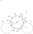
- a bottle can manufacturing apparatus 1 is for forming a mouth portion in a bottomed cylindrical can body and includes a plurality of necking processing parts 2 and a trimming processing part 3.
- Each necking processing part 2 includes a rotating turret 21 that performs necking processing while moving the can body around a rotation axis 20 thereof
- the trimming processing part 3 includes a rotating turret 31 that performs trimming processing while moving the can body around the rotation axis 30 and rotating the can body.
- one stage of necking processing is performed by one necking processing part 2.
- the plurality of necking processing parts 2 are continuously disposed via a coupling turret 4, and the can body supplied to one rotating turret 21 via the coupling turret 4 undergoes one stage of necking processing while moving around the rotation axis 20 by a predetermined angle (for example, 120°), and is subjected to multi-stage necking processing by being processed in sequence by the plurality of necking processing parts 2.
- the trimming processing part 3 is continuously disposed with one of the necking processing parts 2, and eliminates an upper end part of the can body by a predetermined height by slit processing in order to perform slit processing of the upper end part of the can body using the one trimming processing part 3 to adjust a height of the can body to a predetermined height.
- the can body transferred from one necking processing part 2 to the coupling turret 4 is supplied to the rotating turret 31 of the trimming processing part 3 via the coupling turret 4.
- the can body supplied to the rotating turret 31 is subjected to slit processing of the upper end part while rotating when it moves around the rotation axis 30 by a predetermined angle (for example, 120°).
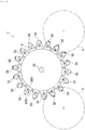
- the rotating turret 21 of each of the necking processing parts 2 includes a plurality of can body holding parts 21P around the rotation axis 20.
- ten can body holding parts 21P are provided around the rotation axis 20 at every angle of 36°.
- One can body is held in each of the can body holding parts 21P, and when the rotating turret 21 makes one rotation, one stage of necking processing is performed for the can bodies corresponding to the number (ten in the illustrated example) of can body holding parts 21P.
- the can bodies held by the can body holding parts 21P move around the rotation axis 20 with the rotation of the rotating turret 21.
- necking processing is performed for the can body W held by each can body holding part 21P using a necking tool 22.
- One necking tool 22 corresponds to one can body holding part 21P, and the necking tool 22 moves in synchronization with the rotation of the rotating turret 21.
- an inner tool 22B and an outer tool 22C are arranged around a center shaft 22A arranged coaxially with a can axis O.
- the outer tool 22C has an annular shape, and an inner diameter thereof is smaller by about 1 to 2 mm than an outside diameter of an opening part of the can body W.
- the inner tool 22B has an outside diameter which is smaller by about 1 to 2 mm than an inner diameter of the opening part of the can body W and is disposed inside the can body W.
- necking processing is performed on the upper end part of the can body W.
- the inner tool 22B and the can body holding part 21P move forward and backward in a direction of the can axis O in synchronization with the rotation of the rotating turret 21.
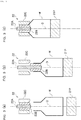
- the necking tool 22 and the can body holding part 21P are separated from the can body W as shown in Fig. 3(a) .
- the rotating turret 21 rotates, as shown in Fig. 3(b)
- the can body holding part 21P moves toward the can body W and holds a bottom part of the can body W
- the inner tool 22B moves toward the can body W and is inserted into the opening part of the can body W.
- the inner tool 22B, the can body W, and the can body holding part 21P integrally move toward the outer tool 22C, and as shown in Fig. 3(c) , the upper end part of the can body W is inserted between the inner tool 22B and the outer tool 22C, so that one stage of necking processing is performed.
- Fig. 4 shows the trimming processing part 3.
- 18 can body holding parts (not shown) are provided on the rotating turret 31 of the trimming processing part 3, and one trimming tool 32 is provided for each can body holding part.
- Each can body holding part is configured to be rotatable around the can axis, and the can body held by each can body holding part rotates with rotation of the can body holding part.
- Each trimming tool 32 includes an inner tool 32A and an outer tool 32B.
- the inner tool 32A is arranged inside the can body, the outer tool 32B is arranged outside the can body, and the upper end part of the can body W is sandwiched between a cutting part of the inner tool 32A and a cutting part of the outer tool 32B and is sheared while the can body W rotates, whereby the slit processing is performed on the upper end part of the can body.
- the trimming processing part 3 performs slit processing with the rotation of the rotating turret 31. That is, the can body held by the can body holding part of the rotating turret 31 is subjected to slit processing using the inner tool 32A and the outer tool 32B while moving around the rotation axis 30 and rotating.
- the outer tool 32B of the trimming tool 32 has a cutting part 32B1 and a relief part 32B2 around a rotation axis thereof.
- the relief part 32B2 is provided around the rotation axis to take up a predetermined angle (for example, 160°) out of 360°, and a part taking up the remaining angle (for example, 200°) forms the cutting part 32B1.
- the inner tool 32A of the trimming tool 32 has a cutting part 32A1 on the entire circumference around the rotation axis.
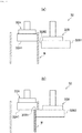
- a distance between the axes of the inner tool 32A and the outer tool 32B is constant, a gap is formed between the inner tool 32A and the outer tool 32B as shown in Fig. 6(a) at the timing when the relief part 32B2 approaches the inner tool 32A, and at that timing, the upper end part of the can body W is inserted between the inner tool 32A and the outer tool 32B.
- the can body W is sandwiched between the cutting part 32B1 of the outer tool 32B and the cutting part 32A1 of the inner tool 32A with the rotation of the outer tool 32B and the inner tool 32A, and the entire circumference of the can body W is sheared while the can body W rotates, whereby slit processing is performed on a periphery of the upper end part of the can body W.
- the upper end part of the can body W is separated from the can body into a single ring shape and recovered by a recovery apparatus (not shown).
- the number of necking processing parts 2 can be appropriately set in accordance with the number of stages of the necking processing.
- a first stage of trimming processing is performed by the trimming processing part 3.
- formation of a bead part or a screw part is performed on the mouth portion, and if necessary, necking processing is carried out in several stages by the necking processing parts 2.
- formation of a curled part is performed, whereby the bottle can in which the mouth portion has been formed can be obtained.
- the height of the upper end part of the can body W may become uneven when a plurality of stages of necking processing is performed, and a problem may occur if the next stage of necking processing is performed in the above state. For that reason, the trimming processing part 3 may be provided in the middle of the plurality of necking processing part 2 as necessary.
- a ring-shaped cut end is generated by the slit processing using the trimming processing part 2, but formation of the mouth portion can be completed without generating fine shavings. This eliminates the need for cleaning and drying after the trimming process, and can significantly improve the productivity of the bottle can.
Landscapes
- Engineering & Computer Science (AREA)
- Mechanical Engineering (AREA)
- Life Sciences & Earth Sciences (AREA)
- Forests & Forestry (AREA)
- Containers Having Bodies Formed In One Piece (AREA)
Abstract
Description
- The present invention relates to a bottle can manufacturing apparatus and a bottle can manufacturing method.
- A bottle can in which beverages or the like is to be filled is a can container having a bottle shape in which a mouth portion has a reduced diameter, and one with a re-pluggable screw type cap-attached container is generally used.
- For example, in the case of an aluminum can, in a bottle can manufacturing process, an aluminum plate is punched out and subjected to shallow squeezing to form a base cup, the formed cup is squeezed and drawn to form a can barrel, the can barrel is trimmed to align a height of an upper part thereof, processes such as cleaning, printing, and inner coating are performed as necessary, and then a mouth portion formation step is performed. In the mouth portion formation step, necking, trimming, formation of a screw part, formation of a curled part, etc., are performed, and also in this case, trimming for adjusting a top height of the mouth portion is performed before the screw part and the curled part are formed.
- In the trimming performed in the mouth portion formation step, adjustment of a can height is performed by cutting an upper end part thereof. A trimming apparatus used in this step is, for example, an apparatus or the like which includes a cutting tool for cutting an opening edge of the can body, a guide part disposed inside an opening part of the can body, and a suction duct for sucking shavings generated by cutting with the cutting tool (for example, see PTL 1).
- [PTL 1] Japanese Patent Application Publication No.
2005-40803 - According to the conventional apparatus mentioned above, since shavings are generated by trimming in the mouth portion formation step, it is difficult to completely remove fine shavings even when the trimming apparatus having the suction duct is used as in the conventional technique mentioned above, and thus it is inevitable to clean and dry the can body after the mouth portion formation step.
- Cleaning and drying of the can body performed after the mouth portion formation step greatly affects productivity of the bottle can since processing time therefor is added. For this reason, in order to obtain high productivity, trimming (adjustment of the can height) that does not generate shavings in the mouth portion formation step is required so that cleaning and drying become unnecessary.
- The present invention has an object to cope with such situations. That is, an object of the present invention is to provide a bottle can manufacturing apparatus in which no fine shavings are generated in a mouth portion formation step and cleaning and drying after the mouth portion formation step are not unnecessary.
- In order to solve such problems, the present invention has the following configurations.
- A bottle can manufacturing apparatus for forming a mouth portion in a bottomed cylindrical can body includes necking processing parts each of which performs necking processing while moving the can body around a rotation axis, and trimming processing parts each of which performs slit processing on an upper end part of the can body to perform trimming while moving the can body around the rotation axis and rotating the can body, and wherein a plurality of the necking processing parts are continuously disposed, and the trimming processing parts are continuously disposed for at least one of the necking processing parts.
- A bottle can manufacturing method for forming a mouth portion in a bottomed cylindrical can body includes: performing a plurality of stages of necking processing in sequence in which each stage of the necking processing is performed while moving the can body around a rotation axis, and performing slit processing on an upper end part of the can body to perform trimming in sequence with at least one stage of the necking processing while moving the can body around the rotation axis and rotating the can body.
- According to the present invention having such features, since there can be performed manufacturing of a bottle can in which no fine shavings are generated in a mouth portion formation step and cleaning and drying after the mouth portion formation step are unnecessary, productivity of the bottle can be significantly improved.
-
- [
Fig. 1] Fig. 1 is an explanatory diagram showing a bottle can manufacturing apparatus according to an embodiment of the present invention. - [
Fig. 2] Fig. 2 is an explanatory diagram showing a rotating turret of a necking processing part. - [
Fig. 3] Fig. 3 is an explanatory diagram showing an operation of a necking tool of the necking processing part, (a) shows a state immediately after a can body is supplied to the rotating turret, (b) shows a state in which the rotating turret is rotated thereafter, and (c) shows a state in which an upper end part of the can body is inserted between an inner tool and an outer tool thereafter. - [
Fig. 4] Fig. 4 is an explanatory diagram showing a trimming processing part. - [
Fig. 5] Fig. 5 is an explanatory diagram showing a trimming tool of the trimming processing part. - [
Fig. 6] Fig. 6 is a cross-sectional view taken along line A-A ofFig. 5 , (a) shows a state in which a gap is formed between the inner tool and the outer tool, and (b) shows a state in which slit processing is performed by the inner tool and the outer tool. - Hereinafter, embodiments of the present invention will be described with reference to the figures. In the following description, the same reference numeral in different figures indicates a part having the same function, and repeated descriptions of each figure will be omitted as appropriate.
- As shown in
Fig. 1 , a bottle can manufacturing apparatus 1 is for forming a mouth portion in a bottomed cylindrical can body and includes a plurality ofnecking processing parts 2 and atrimming processing part 3. Eachnecking processing part 2 includes arotating turret 21 that performs necking processing while moving the can body around arotation axis 20 thereof, and thetrimming processing part 3 includes arotating turret 31 that performs trimming processing while moving the can body around therotation axis 30 and rotating the can body. - In the
necking processing parts 2, one stage of necking processing is performed by onenecking processing part 2. The plurality ofnecking processing parts 2 are continuously disposed via acoupling turret 4, and the can body supplied to one rotatingturret 21 via thecoupling turret 4 undergoes one stage of necking processing while moving around therotation axis 20 by a predetermined angle (for example, 120°), and is subjected to multi-stage necking processing by being processed in sequence by the plurality ofnecking processing parts 2. - The
trimming processing part 3 is continuously disposed with one of thenecking processing parts 2, and eliminates an upper end part of the can body by a predetermined height by slit processing in order to perform slit processing of the upper end part of the can body using the onetrimming processing part 3 to adjust a height of the can body to a predetermined height. The can body transferred from onenecking processing part 2 to thecoupling turret 4 is supplied to the rotatingturret 31 of thetrimming processing part 3 via thecoupling turret 4. The can body supplied to the rotatingturret 31 is subjected to slit processing of the upper end part while rotating when it moves around therotation axis 30 by a predetermined angle (for example, 120°). - As shown in
Fig. 2 , the rotatingturret 21 of each of thenecking processing parts 2 includes a plurality of canbody holding parts 21P around therotation axis 20. In the illustrated example, ten canbody holding parts 21P are provided around therotation axis 20 at every angle of 36°. One can body is held in each of the canbody holding parts 21P, and when the rotatingturret 21 makes one rotation, one stage of necking processing is performed for the can bodies corresponding to the number (ten in the illustrated example) of canbody holding parts 21P. The can bodies held by the canbody holding parts 21P move around therotation axis 20 with the rotation of the rotatingturret 21. - As shown in
Fig. 3 , necking processing is performed for the can body W held by each canbody holding part 21P using anecking tool 22. Onenecking tool 22 corresponds to one canbody holding part 21P, and thenecking tool 22 moves in synchronization with the rotation of the rotatingturret 21. - In the
necking tool 22, aninner tool 22B and anouter tool 22C are arranged around acenter shaft 22A arranged coaxially with a can axis O. Theouter tool 22C has an annular shape, and an inner diameter thereof is smaller by about 1 to 2 mm than an outside diameter of an opening part of the can body W. Theinner tool 22B has an outside diameter which is smaller by about 1 to 2 mm than an inner diameter of the opening part of the can body W and is disposed inside the can body W. In addition, by inserting the upper end part of the can body W between theinner tool 22B and theouter tool 22C, necking processing is performed on the upper end part of the can body W. - The
inner tool 22B and the canbody holding part 21P move forward and backward in a direction of the can axis O in synchronization with the rotation of the rotatingturret 21. Immediately after the can body W is supplied from thecoupling turret 4 to the rotatingturret 21, thenecking tool 22 and the canbody holding part 21P are separated from the can body W as shown inFig. 3(a) . Thereafter, when the rotatingturret 21 rotates, as shown inFig. 3(b) , the canbody holding part 21P moves toward the can body W and holds a bottom part of the can body W, and theinner tool 22B moves toward the can body W and is inserted into the opening part of the can body W. Thereafter, theinner tool 22B, the can body W, and the canbody holding part 21P integrally move toward theouter tool 22C, and as shown inFig. 3(c) , the upper end part of the can body W is inserted between theinner tool 22B and theouter tool 22C, so that one stage of necking processing is performed. -
Fig. 4 shows thetrimming processing part 3. In the illustrated example, 18 can body holding parts (not shown) are provided on the rotatingturret 31 of thetrimming processing part 3, and onetrimming tool 32 is provided for each can body holding part. Each can body holding part is configured to be rotatable around the can axis, and the can body held by each can body holding part rotates with rotation of the can body holding part. Eachtrimming tool 32 includes aninner tool 32A and anouter tool 32B. Theinner tool 32A is arranged inside the can body, theouter tool 32B is arranged outside the can body, and the upper end part of the can body W is sandwiched between a cutting part of theinner tool 32A and a cutting part of theouter tool 32B and is sheared while the can body W rotates, whereby the slit processing is performed on the upper end part of the can body. - Similar to the
necking processing part 2, thetrimming processing part 3 performs slit processing with the rotation of the rotatingturret 31. That is, the can body held by the can body holding part of the rotatingturret 31 is subjected to slit processing using theinner tool 32A and theouter tool 32B while moving around therotation axis 30 and rotating. - As shown in
Fig. 5 , theouter tool 32B of thetrimming tool 32 has a cutting part 32B1 and a relief part 32B2 around a rotation axis thereof. The relief part 32B2 is provided around the rotation axis to take up a predetermined angle (for example, 160°) out of 360°, and a part taking up the remaining angle (for example, 200°) forms the cutting part 32B1. Also, theinner tool 32A of thetrimming tool 32 has a cutting part 32A1 on the entire circumference around the rotation axis. - A distance between the axes of the
inner tool 32A and theouter tool 32B is constant, a gap is formed between theinner tool 32A and theouter tool 32B as shown inFig. 6(a) at the timing when the relief part 32B2 approaches theinner tool 32A, and at that timing, the upper end part of the can body W is inserted between theinner tool 32A and theouter tool 32B. - Then, as shown in
Fig. 6(b) , the can body W is sandwiched between the cutting part 32B1 of theouter tool 32B and the cutting part 32A1 of theinner tool 32A with the rotation of theouter tool 32B and theinner tool 32A, and the entire circumference of the can body W is sheared while the can body W rotates, whereby slit processing is performed on a periphery of the upper end part of the can body W. As a result, the upper end part of the can body W is separated from the can body into a single ring shape and recovered by a recovery apparatus (not shown). - In the bottle can manufacturing apparatus 1 shown in
Fig. 1 , the number ofnecking processing parts 2 can be appropriately set in accordance with the number of stages of the necking processing. In addition, after predetermined necking processing are performed, a first stage of trimming processing is performed by thetrimming processing part 3. Thereafter, formation of a bead part or a screw part is performed on the mouth portion, and if necessary, necking processing is carried out in several stages by the neckingprocessing parts 2. Then, after a second stage of trimming processing is carried out, formation of a curled part is performed, whereby the bottle can in which the mouth portion has been formed can be obtained. - Further, the height of the upper end part of the can body W may become uneven when a plurality of stages of necking processing is performed, and a problem may occur if the next stage of necking processing is performed in the above state. For that reason, the trimming
processing part 3 may be provided in the middle of the plurality of neckingprocessing part 2 as necessary. - As a result, according to the bottle can manufacturing apparatus 1 according to the embodiment of the present invention, a ring-shaped cut end is generated by the slit processing using the
trimming processing part 2, but formation of the mouth portion can be completed without generating fine shavings. This eliminates the need for cleaning and drying after the trimming process, and can significantly improve the productivity of the bottle can. -
- 1
- Bottle can manufacturing apparatus
- 2
- Necking processing part
- 3
- Trimming processing part
- 20, 30
- Rotation axis
- 21, 31
- Rotating turret
- 4
- Coupling turret
- 21P
- Can body holding part
- 22
- Necking tool
- 22A
- Center shaft
- 22B
- Inner tool
- 22C
- Outer tool
- 32
- Trimming tool
- 32A
- Inner tool
- 32B
- Outer tool
- 32A1, 32B1
- Cutting part
- 32B2
- Relief part
Claims (6)
- A bottle can manufacturing apparatus for forming a mouth portion in a bottomed cylindrical can body, comprising:necking processing parts each of which performs necking processing while moving the can body around a rotation axis; anda trimming processing part which performs slit processing on an upper end part of the can body to perform trimming while moving the can body around a rotation axis and rotating the can body,wherein the necking processing parts are continuously disposed, andthe trimming processing part is continuously disposed at at least one of the necking processing parts.
- The bottle can manufacturing apparatus according to claim 1, wherein the trimming processing part is continuously disposed in the middle of the necking processing parts continuously disposed.
- The bottle can manufacturing apparatus according to claim 1 or 2, wherein the necking processing parts and the trimming processing part include a rotating turret having a plurality of can body holding parts around a rotation axis thereof.
- A bottle can manufacturing method for forming a mouth portion in a bottomed cylindrical can body, comprising:performing a plurality of stages of necking processing in sequence in which each stage of the necking processing is performed while moving the can body around a rotation axis; andperforming slit processing on an upper end part of the can body to perform trimming while moving the can body around a rotation axis and rotating the can body in sequence with at least one stage of the necking processing.
- The bottle can manufacturing method according to claim 4, wherein the trimming is performed in sequence with the necking processing in the middle of the necking processing performed in sequence in the plurality of stages.
- The bottle can manufacturing method according to claim 4 or 5, wherein formation of a screw part and a curled part is performed after the trimming.
Applications Claiming Priority (2)
| Application Number | Priority Date | Filing Date | Title |
|---|---|---|---|
| JP2017219129A JP7039943B2 (en) | 2017-11-14 | 2017-11-14 | Bottle can manufacturing equipment and bottle can manufacturing method |
| PCT/JP2018/030650 WO2019097789A1 (en) | 2017-11-14 | 2018-08-20 | Bottle-shaped can manufacturing device and bottle-shaped can manufacturing method |
Publications (2)
| Publication Number | Publication Date |
|---|---|
| EP3711875A1 true EP3711875A1 (en) | 2020-09-23 |
| EP3711875A4 EP3711875A4 (en) | 2021-08-25 |
Family
ID=66538648
Family Applications (1)
| Application Number | Title | Priority Date | Filing Date |
|---|---|---|---|
| EP18877336.0A Pending EP3711875A4 (en) | 2017-11-14 | 2018-08-20 | Bottle-shaped can manufacturing device and bottle-shaped can manufacturing method |
Country Status (7)
| Country | Link |
|---|---|
| US (1) | US20210187587A1 (en) |
| EP (1) | EP3711875A4 (en) |
| JP (1) | JP7039943B2 (en) |
| KR (1) | KR102387724B1 (en) |
| CN (1) | CN111278583A (en) |
| TW (1) | TWI670202B (en) |
| WO (1) | WO2019097789A1 (en) |
Families Citing this family (4)
| Publication number | Priority date | Publication date | Assignee | Title |
|---|---|---|---|---|
| CN112105916B (en) * | 2018-05-11 | 2024-01-02 | 斯多里机械有限责任公司 | Feed into components Full inspection of components |
| US11440078B2 (en) * | 2020-09-15 | 2022-09-13 | Stolle Machinery Company, Llc | Drive assembly |
| CN113909399A (en) * | 2021-09-10 | 2022-01-11 | 苏州斯莱克精密设备股份有限公司 | Multi-station neck forming equipment for pop-top can |
| CN120882511A (en) | 2023-03-17 | 2025-10-31 | 贝瓦克生产机械有限公司 | Metal container with bearing ring and method for manufacturing same |
Family Cites Families (16)
| Publication number | Priority date | Publication date | Assignee | Title |
|---|---|---|---|---|
| US4030432A (en) * | 1975-01-24 | 1977-06-21 | Gulf & Western Manufacturing Company (Hastings) | Can trimming apparatus |
| JPS5471485A (en) * | 1978-08-14 | 1979-06-08 | Reynolds Metals Co | Apparatus for trimming container |
| NL8201746A (en) * | 1982-04-27 | 1983-11-16 | Thomassen & Drijver | Apparatus for cutting the edge of a pipe or can in a plane transverse to the longitudinal axis. |
| JPH084862B2 (en) * | 1986-10-27 | 1996-01-24 | 武内プレス工業株式会社 | Method for producing smooth neck-in can and apparatus used for the method |
| US5018379A (en) * | 1989-02-22 | 1991-05-28 | Mitsubishi Metal Corporation | Apparatus and method for crimping end of can body |
| US5694822A (en) * | 1993-08-16 | 1997-12-09 | Reynolds Metals Company | Apparatus for trimming can bodies |
| EP1136154B1 (en) * | 1999-09-30 | 2008-08-27 | Daiwa Can Company | Method of manufacturing bottle type can |
| JP3561796B2 (en) * | 2000-02-02 | 2004-09-02 | 武内プレス工業株式会社 | Metal can with screw |
| JP2002102968A (en) * | 2000-09-25 | 2002-04-09 | Mitsubishi Materials Corp | Can body manufacturing apparatus and can body manufacturing method |
| JP4581296B2 (en) * | 2001-06-19 | 2010-11-17 | 三菱電機株式会社 | Press unit with rotation function |
| US20040035871A1 (en) * | 2002-08-20 | 2004-02-26 | Thomas Chupak | Aluminum aerosol can and aluminum bottle and method of manufacture |
| JP4405193B2 (en) | 2003-07-23 | 2010-01-27 | ユニバーサル製缶株式会社 | Trimming device |
| US8037728B2 (en) * | 2003-08-28 | 2011-10-18 | Universal Can Corporation | Apparatus for producing bottle can |
| US8297098B2 (en) * | 2009-02-26 | 2012-10-30 | Belvac Production Machinery, Inc. | Dual ram assembly for necker machine |
| CA2903308C (en) * | 2013-03-15 | 2018-05-01 | Ball Corporation | Method and apparatus for forming a threaded neck on a metallic bottle |
| ES2763553T3 (en) * | 2015-09-08 | 2020-05-29 | Belvac Production Machinery Inc | Smoothing Roller Assembly |
-
2017
- 2017-11-14 JP JP2017219129A patent/JP7039943B2/en active Active
-
2018
- 2018-08-20 KR KR1020207011693A patent/KR102387724B1/en active Active
- 2018-08-20 US US16/761,320 patent/US20210187587A1/en not_active Abandoned
- 2018-08-20 CN CN201880070223.1A patent/CN111278583A/en active Pending
- 2018-08-20 WO PCT/JP2018/030650 patent/WO2019097789A1/en not_active Ceased
- 2018-08-20 EP EP18877336.0A patent/EP3711875A4/en active Pending
- 2018-10-05 TW TW107135194A patent/TWI670202B/en active
Also Published As
| Publication number | Publication date |
|---|---|
| TWI670202B (en) | 2019-09-01 |
| EP3711875A4 (en) | 2021-08-25 |
| KR102387724B1 (en) | 2022-04-18 |
| US20210187587A1 (en) | 2021-06-24 |
| TW201918427A (en) | 2019-05-16 |
| JP2019089096A (en) | 2019-06-13 |
| WO2019097789A1 (en) | 2019-05-23 |
| JP7039943B2 (en) | 2022-03-23 |
| KR20200058481A (en) | 2020-05-27 |
| CN111278583A (en) | 2020-06-12 |
Similar Documents
| Publication | Publication Date | Title |
|---|---|---|
| US20210187587A1 (en) | Bottle can manufacturing apparatus and bottle can manufacturing method | |
| EP2835188B1 (en) | Method and device for manufacturing threaded bottle can | |
| EP2251114B1 (en) | Method and apparatus for trimming a can | |
| EP2001616B1 (en) | Apparatus for can expansion | |
| CN109604472A (en) | A kind of sleeve manufacturing process | |
| JP4149191B2 (en) | Metal bottle can manufacturing method and manufacturing apparatus | |
| JP2008260042A (en) | Press forming apparatus | |
| US20160067799A1 (en) | Height adjustment apparatus for a can body | |
| US6763752B2 (en) | Apparatus for trimming a flange on a cylindrical opening of a plastic container | |
| JP4850783B2 (en) | Metal bottle can manufacturing method and manufacturing apparatus | |
| JP2018099729A (en) | Manufacturing method of can | |
| CN109604473B (en) | Die for sleeve stamping and forming and use method thereof | |
| EP2391466B1 (en) | Necker infeed | |
| JP2009173446A (en) | Conveying wheel, can manufacturing apparatus, and can manufacturing method | |
| US3481232A (en) | Method and apparatus for making nonpilferable container closures | |
| JP6843713B2 (en) | Can molding equipment | |
| JP6922356B2 (en) | How to make bottle cans | |
| WO2018008200A1 (en) | Forming processing unit and bottle can manufacturing device | |
| US20170341129A1 (en) | Can forming machine | |
| JP2018075634A (en) | Can molding equipment | |
| US20190255593A1 (en) | Method and apparatus for trimming a can | |
| CN117446717A (en) | Equipment used to separate, process and reassemble multi-piece objects | |
| EP2342030A1 (en) | Improvements in or relating to a method of forming metal articles | |
| JP2000202554A (en) | How to trim a seamless can | |
| JP2018001253A (en) | Can production method |
Legal Events
| Date | Code | Title | Description |
|---|---|---|---|
| STAA | Information on the status of an ep patent application or granted ep patent |
Free format text: STATUS: THE INTERNATIONAL PUBLICATION HAS BEEN MADE |
|
| PUAI | Public reference made under article 153(3) epc to a published international application that has entered the european phase |
Free format text: ORIGINAL CODE: 0009012 |
|
| STAA | Information on the status of an ep patent application or granted ep patent |
Free format text: STATUS: REQUEST FOR EXAMINATION WAS MADE |
|
| 17P | Request for examination filed |
Effective date: 20200422 |
|
| AK | Designated contracting states |
Kind code of ref document: A1 Designated state(s): AL AT BE BG CH CY CZ DE DK EE ES FI FR GB GR HR HU IE IS IT LI LT LU LV MC MK MT NL NO PL PT RO RS SE SI SK SM TR |
|
| AX | Request for extension of the european patent |
Extension state: BA ME |
|
| DAV | Request for validation of the european patent (deleted) | ||
| DAX | Request for extension of the european patent (deleted) | ||
| A4 | Supplementary search report drawn up and despatched |
Effective date: 20210722 |
|
| RIC1 | Information provided on ipc code assigned before grant |
Ipc: B21D 51/26 20060101AFI20210716BHEP Ipc: B21D 51/38 20060101ALI20210716BHEP Ipc: B23D 21/04 20060101ALI20210716BHEP Ipc: B23D 31/00 20060101ALI20210716BHEP |
|
| STAA | Information on the status of an ep patent application or granted ep patent |
Free format text: STATUS: EXAMINATION IS IN PROGRESS |
|
| 17Q | First examination report despatched |
Effective date: 20240605 |