EP3711825A1 - Adjustable weight shot - Google Patents
Adjustable weight shot Download PDFInfo
- Publication number
- EP3711825A1 EP3711825A1 EP20158666.6A EP20158666A EP3711825A1 EP 3711825 A1 EP3711825 A1 EP 3711825A1 EP 20158666 A EP20158666 A EP 20158666A EP 3711825 A1 EP3711825 A1 EP 3711825A1
- Authority
- EP
- European Patent Office
- Prior art keywords
- weight
- cap
- shot
- weight portion
- cavity
- Prior art date
- Legal status (The legal status is an assumption and is not a legal conclusion. Google has not performed a legal analysis and makes no representation as to the accuracy of the status listed.)
- Withdrawn
Links
- 230000008878 coupling Effects 0.000 claims abstract description 36
- 238000010168 coupling process Methods 0.000 claims abstract description 36
- 238000005859 coupling reaction Methods 0.000 claims abstract description 36
- 230000037396 body weight Effects 0.000 claims description 15
- 239000000463 material Substances 0.000 description 12
- 238000012549 training Methods 0.000 description 11
- 238000004519 manufacturing process Methods 0.000 description 8
- 230000000386 athletic effect Effects 0.000 description 3
- 238000000034 method Methods 0.000 description 3
- 230000004048 modification Effects 0.000 description 3
- 238000012986 modification Methods 0.000 description 3
- 210000003205 muscle Anatomy 0.000 description 3
- 229910000831 Steel Inorganic materials 0.000 description 2
- XAGFODPZIPBFFR-UHFFFAOYSA-N aluminium Chemical compound [Al] XAGFODPZIPBFFR-UHFFFAOYSA-N 0.000 description 2
- 229910052782 aluminium Inorganic materials 0.000 description 2
- 230000008859 change Effects 0.000 description 2
- 239000004033 plastic Substances 0.000 description 2
- 229920003023 plastic Polymers 0.000 description 2
- 239000004576 sand Substances 0.000 description 2
- 239000010959 steel Substances 0.000 description 2
- 229910001369 Brass Inorganic materials 0.000 description 1
- 229910000906 Bronze Inorganic materials 0.000 description 1
- 229910001018 Cast iron Inorganic materials 0.000 description 1
- 229920001875 Ebonite Polymers 0.000 description 1
- CWYNVVGOOAEACU-UHFFFAOYSA-N Fe2+ Chemical compound [Fe+2] CWYNVVGOOAEACU-UHFFFAOYSA-N 0.000 description 1
- 229910001209 Low-carbon steel Inorganic materials 0.000 description 1
- 240000003864 Ulex europaeus Species 0.000 description 1
- 208000027418 Wounds and injury Diseases 0.000 description 1
- 230000006978 adaptation Effects 0.000 description 1
- 229910045601 alloy Inorganic materials 0.000 description 1
- 239000000956 alloy Substances 0.000 description 1
- 239000010951 brass Substances 0.000 description 1
- 239000010974 bronze Substances 0.000 description 1
- 239000000919 ceramic Substances 0.000 description 1
- 238000004140 cleaning Methods 0.000 description 1
- 230000000295 complement effect Effects 0.000 description 1
- 238000010276 construction Methods 0.000 description 1
- KUNSUQLRTQLHQQ-UHFFFAOYSA-N copper tin Chemical compound [Cu].[Sn] KUNSUQLRTQLHQQ-UHFFFAOYSA-N 0.000 description 1
- 230000006378 damage Effects 0.000 description 1
- 230000003247 decreasing effect Effects 0.000 description 1
- 238000009826 distribution Methods 0.000 description 1
- 238000005553 drilling Methods 0.000 description 1
- 229920001971 elastomer Polymers 0.000 description 1
- 238000009713 electroplating Methods 0.000 description 1
- 239000012530 fluid Substances 0.000 description 1
- 230000006870 function Effects 0.000 description 1
- 208000014674 injury Diseases 0.000 description 1
- 230000013011 mating Effects 0.000 description 1
- 230000007246 mechanism Effects 0.000 description 1
- 238000010422 painting Methods 0.000 description 1
- 230000000717 retained effect Effects 0.000 description 1
- 239000005060 rubber Substances 0.000 description 1
- 239000007787 solid Substances 0.000 description 1
- 229910001220 stainless steel Inorganic materials 0.000 description 1
- 239000004575 stone Substances 0.000 description 1
- 230000007704 transition Effects 0.000 description 1
- WFKWXMTUELFFGS-UHFFFAOYSA-N tungsten Chemical compound [W] WFKWXMTUELFFGS-UHFFFAOYSA-N 0.000 description 1
- 239000010937 tungsten Substances 0.000 description 1
- 229910052721 tungsten Inorganic materials 0.000 description 1
Images










Classifications
-
- A—HUMAN NECESSITIES
- A63—SPORTS; GAMES; AMUSEMENTS
- A63B—APPARATUS FOR PHYSICAL TRAINING, GYMNASTICS, SWIMMING, CLIMBING, OR FENCING; BALL GAMES; TRAINING EQUIPMENT
- A63B21/00—Exercising apparatus for developing or strengthening the muscles or joints of the body by working against a counterforce, with or without measuring devices
- A63B21/06—User-manipulated weights
- A63B21/072—Dumb-bells, bar-bells or the like, e.g. weight discs having an integral peripheral handle
- A63B21/075—Dumb-bells, bar-bells or the like, e.g. weight discs having an integral peripheral handle with variable weights, e.g. weight systems with weight selecting means for bar-bells or dumb-bells
-
- A—HUMAN NECESSITIES
- A63—SPORTS; GAMES; AMUSEMENTS
- A63B—APPARATUS FOR PHYSICAL TRAINING, GYMNASTICS, SWIMMING, CLIMBING, OR FENCING; BALL GAMES; TRAINING EQUIPMENT
- A63B37/00—Solid balls; Rigid hollow balls; Marbles
- A63B37/0098—Rigid hollow balls, e.g. for pétanque
-
- A—HUMAN NECESSITIES
- A63—SPORTS; GAMES; AMUSEMENTS
- A63B—APPARATUS FOR PHYSICAL TRAINING, GYMNASTICS, SWIMMING, CLIMBING, OR FENCING; BALL GAMES; TRAINING EQUIPMENT
- A63B37/00—Solid balls; Rigid hollow balls; Marbles
- A63B37/02—Special cores
-
- A—HUMAN NECESSITIES
- A63—SPORTS; GAMES; AMUSEMENTS
- A63B—APPARATUS FOR PHYSICAL TRAINING, GYMNASTICS, SWIMMING, CLIMBING, OR FENCING; BALL GAMES; TRAINING EQUIPMENT
- A63B37/00—Solid balls; Rigid hollow balls; Marbles
- A63B37/02—Special cores
- A63B37/04—Rigid cores
-
- A—HUMAN NECESSITIES
- A63—SPORTS; GAMES; AMUSEMENTS
- A63B—APPARATUS FOR PHYSICAL TRAINING, GYMNASTICS, SWIMMING, CLIMBING, OR FENCING; BALL GAMES; TRAINING EQUIPMENT
- A63B37/00—Solid balls; Rigid hollow balls; Marbles
- A63B37/12—Special coverings, i.e. outer layer material
-
- A—HUMAN NECESSITIES
- A63—SPORTS; GAMES; AMUSEMENTS
- A63B—APPARATUS FOR PHYSICAL TRAINING, GYMNASTICS, SWIMMING, CLIMBING, OR FENCING; BALL GAMES; TRAINING EQUIPMENT
- A63B43/00—Balls with special arrangements
-
- A—HUMAN NECESSITIES
- A63—SPORTS; GAMES; AMUSEMENTS
- A63B—APPARATUS FOR PHYSICAL TRAINING, GYMNASTICS, SWIMMING, CLIMBING, OR FENCING; BALL GAMES; TRAINING EQUIPMENT
- A63B65/00—Implements for throwing ; Mechanical projectors, e.g. using spring force
- A63B65/06—Heavy throwing-balls, i.e. "medicine balls", shots, weights or stones for putting
-
- A—HUMAN NECESSITIES
- A63—SPORTS; GAMES; AMUSEMENTS
- A63B—APPARATUS FOR PHYSICAL TRAINING, GYMNASTICS, SWIMMING, CLIMBING, OR FENCING; BALL GAMES; TRAINING EQUIPMENT
- A63B37/00—Solid balls; Rigid hollow balls; Marbles
- A63B37/02—Special cores
- A63B37/08—Liquid cores; Plastic cores
- A63B2037/082—Granular, e.g. comprising beads
-
- A—HUMAN NECESSITIES
- A63—SPORTS; GAMES; AMUSEMENTS
- A63B—APPARATUS FOR PHYSICAL TRAINING, GYMNASTICS, SWIMMING, CLIMBING, OR FENCING; BALL GAMES; TRAINING EQUIPMENT
- A63B2209/00—Characteristics of used materials
-
- A—HUMAN NECESSITIES
- A63—SPORTS; GAMES; AMUSEMENTS
- A63B—APPARATUS FOR PHYSICAL TRAINING, GYMNASTICS, SWIMMING, CLIMBING, OR FENCING; BALL GAMES; TRAINING EQUIPMENT
- A63B2244/00—Sports without balls
- A63B2244/14—Shot putting
-
- A—HUMAN NECESSITIES
- A63—SPORTS; GAMES; AMUSEMENTS
- A63B—APPARATUS FOR PHYSICAL TRAINING, GYMNASTICS, SWIMMING, CLIMBING, OR FENCING; BALL GAMES; TRAINING EQUIPMENT
- A63B37/00—Solid balls; Rigid hollow balls; Marbles
- A63B37/02—Special cores
- A63B37/06—Elastic cores
-
- A—HUMAN NECESSITIES
- A63—SPORTS; GAMES; AMUSEMENTS
- A63B—APPARATUS FOR PHYSICAL TRAINING, GYMNASTICS, SWIMMING, CLIMBING, OR FENCING; BALL GAMES; TRAINING EQUIPMENT
- A63B43/00—Balls with special arrangements
- A63B43/04—Balls with special arrangements with an eccentric centre of gravity; with mechanism for changing the centre of gravity
-
- A—HUMAN NECESSITIES
- A63—SPORTS; GAMES; AMUSEMENTS
- A63B—APPARATUS FOR PHYSICAL TRAINING, GYMNASTICS, SWIMMING, CLIMBING, OR FENCING; BALL GAMES; TRAINING EQUIPMENT
- A63B69/00—Training appliances or apparatus for special sports
Definitions
- Shot put is a weight throwing sport. Athletes train with the goal of throwing a heavy, typically spherical, shot as far as possible. As part of the training routine, athletes may use shots of different weights.
- the described embodiments relate generally to an adjustable weight throwing implement, for example, a shot.
- an adjustable weight shot system comprises a core, an inner weight portion, an outer weight portion, a body, and a cap.
- the inner weight portion may be formed of two coupling hemispheres configured to receive the core in an inner weight portion cavity.
- the outer weight portion may be formed of two coupling hemispheres configured to receive the inner weight portion in an outer weight portion cavity.
- the body and cap may be configured to retain the outer weight portion in a body weight cavity defined by the body and the cap.
- an adjustable weight shot system includes intermediate weight portions.
- Each intermediate weight portion may have two coupling hemispheres configured to receive one of a smaller intermediate weight portion and the inner weight portion in an intermediate weight portion cavity.
- an outer surface of the body is larger than an outer surface of the cap.
- the body and the cap may couple in a variety of ways.
- the body and the cap may be coupled with a threaded connection.
- the cap may include a cap sleeve and cap threads may be formed on the cap sleeve.
- an adjustable weight shot includes a body that defines a shot cavity.
- the shot cavity of the adjustable weight shot may be semispherical.
- a first weight portion may be positioned in the shot cavity.
- the first weight portion may be formed of two coupling first weight portion hemispheres.
- the two coupling first weight portion hemispheres may define a first weight cavity.
- a second weight portion may be positioned in the first weight cavity and formed of two coupling second weight portion hemispheres.
- the two coupling second weight portion hemispheres may define a second weight cavity.
- the adjustable weight shot may also include weight portion key holes formed in each removable weight portion. The key holes may aid in separating the two coupling weight portion hemispheres.
- the key holes may be formed near the boundary of the two coupling hemispheres.
- the hemispheres of the removable weight portions interlock using a snap-fit connection.
- the hemispheres of the removable weight portions interlock using threads, pins, bayonet type couplings, or other interlocking devices.
- an adjustable weight shot includes a cap.
- the body may be configured to receive the cap at an opening of the body.
- the cap may include a tool port configured to receive a tool.
- the tool port includes a tool port weight disposed in the tool port.
- the opening in the body has a cap seat and the cap has a cavity sleeve.
- the cavity sleeve is configured to engage the cap seat.
- the shot cavity is semispherical and has a shot cavity diameter. The diameter of the cap seat may be greater than the shot cavity diameter.
- an adjustable weight shot system includes a body and a cap.
- the cap is configured to engage an opening formed in the body.
- the cap may include a tool port.
- an adjustable weight shot system may include a plurality of weight portion, each formed of two coupling hollow hemispheres, may be configured to receive another of the weight portion. In some embodiments, the plurality of weight portions are nested.
- the present disclosure is directed to an adjustable weight shot.
- the adjustable weight shot may be used during athletic training for shot put competitions.
- men's shots weigh 7.260 kilograms and women's shots weight 4 kilograms. Other weights are used in other competitions or at different levels, such as college, junior, school, or masters competitions.
- shot put athletes throw the shot in a specified target area. The distance of the throw is measured. The goal of the competition is to throw the shot as far as possible.
- men's competition shots weigh 7.260 kilograms and women's competition shots weight 4 kilograms
- athletes may travel with several times that weight in practice shot when attending competitions.
- men's practice shots may weigh 4 kilograms, 5 kilograms, and 6 kilograms and women's practice shots may weigh between from 2.5 kilograms to 6.5 kilograms.
- training weights may exceed competition weights.
- men's practice weights may be in excess of 10 kilograms.
- shots have the same diameter as the competition shots, the numerous shots take up a large volume. The weight and volume increases travel strain and may increase travel costs, including, for example, excess weight or baggage charges.
- the present disclosure is directed to an adjustable weight shot.
- the adjustable weight shot has a body and a cap.
- the cap closes a body weight cavity formed in the body.
- the body and the cap together may define the body weight cavity.
- the body may include a cap seat configured to receive the cap and body threads.
- the body threads are configured to engage cap threads on the cap.
- the body weight cavity is configured to receive various weight portions.
- Each weight portions may be formed of two or more portions.
- each weight portions may be spherical and formed of two hemispheres.
- the two hemispheres may be substantially the same size, for example, each substantially half of a sphere.
- the two hemispheres may be of unequal size.
- one hemisphere may be substantially larger than the other hemisphere.
- the two hemispheres of the weight portions may be coupled together to form a weight portion. In some embodiments, the two hemispheres lock together to from the weight portion.
- each weight portion may also include a weight portion cavity configured to receive another weight portion. That is, each weight portion may be configured to receive a weight portion and then be located in a weight portion cavity of another weight portion. In this way, the weight portions may "nest" within one another.
- the weight portions may also nest within the body weight cavity defined by the body and the cap.
- the cap may include a tool port configured to receive a tool. Using a tool in the tool port allows the athlete to increase the torque on the cap to more easily remove the cap from the body. Additionally, some or all of the weight portions may have key ports that help to separate portions of the weight portions from one another or help separate weight portions from each other.
- an adjustable weight shot 100 has a body 102.
- a cap 120 closes an opening 112 in body 102.
- cap 120 and body 102 may be coupled using a threaded connection or other mechanical means.
- FIG. 1 shows body threads 110 located inside opening 112 of body 102.
- Cap threads 130 are on a cap sleeve 128 of cap 120.
- Cap threads 130 are configured to engage body threads 110 to close a body weight cavity 104.
- body 102 defines a body weight cavity 104.
- body 102 and cap 120 define body weight cavity 104.
- FIG. 1 also shows a central axis 300. Central axis 300 extends through the center of body 102 and opening 112.
- the body 102 and/or the cap 120 are substantially rotationally symmetrical about the central axis 300.
- FIG. 1 shows an exploded view of adjustable weight shot 100.
- Weight portions 140 are shown. Weight portions 140 are configured to be housed in body weight cavity 104 of body 102. As shown in FIG. 1 , each weight portion 140 may be formed of one or more portions, for example, two substantially equally sized portions. For example, weight portions 140 may be formed of coupling shells. As shown in FIG. 1 , weight portions 140 are a series of coupling weight shells or hemispheres (corresponding pairs labeled as A and B).
- FIG. 1 shows a first weight shell member 150 having coupling first weight shell member 150A and first weight shell member 150B. First weight shell members 150A, 150B interlock to form first weight shell 150. First weight shell 150 is hollow and defines a shell weight cavity 190 (shown in FIG.
- First weight shell member 150 may be considered an outer weight portion because it is an outer weight portion with respect to one or more other weight portions (i.e. other weight portions are or can be placed inside it).
- second weight shell member 152 is formed of two coupling hemispheres, second weight shell members 152A, 152B.
- FIG. 1 shows third weight shell members 154A, 154B, fourth weight shell members 156A, 156B, and fifth weight shell members 158A, 158B.
- Fifth weight shell member 158 may be considered an inner weight portion because it is located in the interior with respect to other weight portions 140.
- fewer than five weight portions 140 may be used, such as one, two, three, or four sets of weight portions 140. In other embodiments, more than five weigh portions 140 may be used, such as six, seven, eight, nine, or ten weight portions 140.
- Each shell member may form weight cavities configured to receive weight portions.
- a core 160 is located inside a weight portion, such as the inner most weight portion 140. Core 160 is also a weight portion and may be consider as an inner weight portion as well. Core 160 may be hollow or solid. In some embodiments, a core 160 may be distinguished from a weight portion in that a core is not formed from separable portions. In other embodiments, an adjustable weight shot 100 does not include a core 160.
- FIG. 2 shows adjustable weight shot 100 with cap 120 secured to body 102 at opening 112.
- Cap 120 closes opening 112 of body 102.
- a tool port 122 is formed in cap 120.
- Tool port 122 is configured to receive a tool that can be used to aid in the release of cap 120 from body 102.
- the tool is, for example, a hex key.
- the opening 112 of the body 102, the cap 120 itself, and/or the tool port 122 are substantially rotationally symmetrical about an axis, such as the central axis 300.
- the junction between the opening 112 of the body 102 and the cap 120 is substantially circular latitudinal circumference.
- the substantially circular latitudinal circumference is between 200mm and 400mm.
- the substantially circular latitudinal circumference is between 300mm and 350mm, for example, 320mm.
- FIG. 3 shows a cross section of adjustable weight shot 100 taken at the line 3 - 3' in FIG. 2 .
- radially adjacent weight portions 140 are shaded differently.
- FIG. 3 shows weight portions 140 retained in body weight cavity 104 defined by body 102's cavity wall 106 and cap 120's cap cavity wall 126.
- Cap 120 has cap sleeve 128.
- Cap sleeve 128 extends into body 102 and is seated in cap seat 108.
- Cap seat 108 has cap ledge 109.
- Cap ledge 109 may form a transition between body cavity wall 106 and cap seat 108.
- Cap ledge 109 may extend at a right angle relative to cavity wall 106 and cap seat 108.
- cap ledge 109 may be formed at an angle other than 90° relative to cavity wall 106 and cap seat 108.
- cap ledge 109 may be formed at a 45° angle or a 135° angle relative to cavity wall 106.
- cap ledge 109 may be formed at an angle between 45° and 90°, or between 90° and 135°. Using the smaller angles between 45° and 90° may ease cleaning debris, such as dirt, from body weight cavity 104.
- the construction instead of cap sleeve 128 extending into body 102, the construction may differ such that a portion of body 102 extends into a portion of cap 120.
- a washer 192 may be included between cap 120 and body 102. Washer 192 may be made of plastic or other materials and may help seal cap 120 and body 102. Additionally, washer 192 may prevent sticking between cap 120 and body 102. Other features described above could be incorporated into such an embodiment.
- the weight portions 140 illustrated in FIG. 3 are depicted as having varied radial thicknesses. In some embodiments, all weigh portions 140 may have the same radial thickness. In one embodiment, the radial thicknesses of a given weight portion 140 is substantially constant in all radial directions, which is to say the weight portion 140 is substantially symmetrical. In another embodiment, a given weight portion 140 may not be substantially symmetrical. In some embodiments, alternating weight portions 140 arranged radially in a nested fashion may have alternating thinner and thicker radial thicknesses. In other embodiments, a given inner weigh portion 140 may have a thinner or a thicker radial thickness compared to a given outer weight portion 140.
- a given outer weigh portion 140 may have a thinner or a thicker radial thickness compared to a given inner weight portion 140.
- weight portion radial thicknesses may be between 1mm and 5mm, for example 2.5mm.
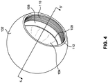
- FIG. 4 shows a perspective view of body 102 for adjustable weight shot 100.
- opening 112 may be smaller than a diameter of adjustable weight shot 100, and/or the circumference of opening 112 may be smaller than the equatorial circumference of the body 102 or shot 100.
- FIG. 5 shows a cross section view of body 102 taken at the line 5 - 5' of FIG. 4 .
- Body 102 has a center 200. Center 200 may be the geometric center of adjustable weight shot 100 when cap 120 is coupled to body 102. In some embodiments center 200 may also be the center of mass of an assembled adjustable weight shot 100.
- body weight cavity 104 may have a cavity radius 202.
- Cavity radius 202 is defined as the distance between center 200 and shot cavity wall 106. In some embodiments cavity radius may be between 30 mm and 50mm. For example, cavity radius may be 45mm.
- Center 200 may also be used to define a shot radius.
- shot radius 208 is the radius of the shot when assembled and also defines the radius of curvature of the outer surfaces of shot 102 and cap 120. In some embodiment shot radius 208 may be between 50 and 80mm. In some embodiments, shot radius 208 may be 65.22mm, giving the adjustable weight shot a diameter of 130.44mm. Shot radius 208 may be governed by athletic standards such as those developed under the International Association of Athletics Federations (IAAF).
- IAAF International Association of Athletics Federations
- FIG. 5 also shows a cap seat width 204 and a cap threaded width 206.
- the cap seat width 204 and the cap threaded width 206 may be substantially the same, while in other embodiments they will differ.
- cap threaded width 206 may be between approximately 12mm and 20mm.
- cap threaded width 206 may be approximately 15mm.
- cap seat width 204 may be between 15mm and 20mm.
- seat cap width 204 may be 18mm.
- Opening radius 214 is a distance between opening 112 and center 200 of body 102.
- Cap seat width 204 may be greater than twice cavity radius 202.
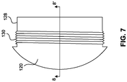
- FIGS. 6 and 7 shows cap 120 with cap cavity 124.
- Cap cavity 124 is bounded by a cap cavity wall 126.
- a cap sleeve 128 surrounds cap cavity 124.
- cap sleeve 128 is substantially cylindrical.
- An upper portion of cap 120 has cap screw threads 130. In one embodiment, when considered in cross section, the cap 120 has five threads. In other embodiments, the cap may have three, four, six, or seven threads.
- Cap threads 130 are configured to engage body threads 110 by screwing into them to secure cap 120 to body 102.
- FIG. 8 is a cross section of cap 120 taken at the line 8 - 8' of FIG. 7 .
- FIG. 8 shows cap 120 with tool port 122.
- the shape of tool port 122 may depend on both the tool that tool port is configured to receive and manufacturing considerations.
- tool port 122 may have a hexagonal shape.
- the hexagonal shape of tool port 122 is configured to mate with a tool (not shown) having a hexagonal shape.
- the tool may be an standard sized hex key, also known as an Allen wrench.
- Tool port 122 may also include a tool port weight 132 located within the tool port, such as at the bottom of tool port 122 as depicted in FIG. 8 .
- tool port weight 132 may be a liner or a filling applied to tool port 122.
- Tool port weight 132 is configured to counter balance the amount of weight removed from adjustable weight shot 100 when tool port 122 is formed. For this reason, in some embodiments, tool port weight 132 may be made of a material having a higher density than the material that makes up cap 120. In some embodiments, tool port weight 132 has a weight equal to approximately the weight of the material removed to from tool port 122. In some embodiments, a tool port plug (not shown) may be used to plug tool port 122.
- tool port 122 may have a threaded top or other means to secure the tool port plug to tool port 122.
- the tool port plug may have a key hole, which may be a configured to receive the edge of a coin, that can be used to loosen tool port plug from tool port 122.
- FIG. 9 shows an exemplary weight portion 140.
- Weight portion 140 is formed of two weight portion hemispheres 150. While the weight portion of FIG. 9 is depicted as having two substantially equal half portion hemispheres 150, in some embodiments, one portion may be larger than the other.
- Weight portions 140 may have a weight portion key port 180 located in or near a seam 174.
- key port 180 may be near seam 174 when it key port 180 is on seam 174 or when key port 180 is adjacent to key port 180. In some embodiments, key port 180 may be located further from seam 174.
- Seam 174 is the division between the two weight portion hemispheres. In some embodiments where one of the two parts of weight portion 140 is larger than the other part, the seam 174 may not divide the weigh portion 140 approximately in half.
- Key port 180 may be used to help an athlete separate two weight portion 140 parts, such as hemispheres 150.
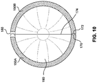
- FIG. 10 shows a cross section of a weight portion 140 taken through the line 10 - 10' shown in FIG. 9 .
- FIG. 10 shows two hemispheres 150A and 150B. The hemispheres meet at seam 174. Hemispheres 150A and 150B may have complementary edges at seam 174. For example, as shown in FIG. 10 , hemisphere 150A may have a step 170 extending from the edge of the hemisphere which is configured to mate with a corresponding recess 172 formed in the edge of hemisphere 150B. Hemispheres 150A and 150B may come together with a mating mechanism such as those shown in FIG. 10 or by other means.
- hemispheres 150A and 150B may have threaded edges such that the athlete can screw hemispheres 150A and 150B together.
- a weight portion cavity 190 is formed inside of weight portion 140 when hemispheres 150A and 150B are brought together.
- the weight portion 140 may not be formed from substantially equal hemispheres, but may be formed from two or more unequally sized portions.
- the total weight of adjustable weight shot 100 can be varied by adding to or removing weight portions 140 from adjustable weight shot 100, or by using weight portions 140 of materials having different volumes, weights, and/or densities.
- a weight portion 140 is made from the same material as body 102, cap 120, and/or core 160.
- one or more of any weight portions 140, the body 102, the cap 120, and the core 160 may be made of different materials having different volumes, weights, and/or densities.
- adjustable weight shot 100 in FIG. 1 shows adjustable weight shot 100 with several nesting weight portions 140.
- core 160 is inside weight portion 158, which is formed from hemispheres 158A and 158A.
- Weight portion 158 is inside weight port 156, which is formed from hemispheres 156A and 156B.
- Weight portion 156 is inside weight port 154, which is formed from hemispheres 154A and 154B.
- Weight portion 154 is inside weight port 152, which is formed from hemispheres 152A and 152B. This continues until weight portion 150, which is formed from hemispheres 150A and 150B, which holds all the preceding weight portions 158 through 152, and core 160.
- weight portions 140 nest inside each other.
- Core 160 may be described as an inner weight portion and weight portion 150 may be an outer weight portion.
- Inner and outer weight portions 140 either may be adjacent to one other or may be separated by another weight portion 140. In some embodiments there are substantially no gaps between adjacent weight portions 140, whereas in other embodiments there are gaps between adjacent weight portions 140.
- Balance may be an important consideration of adjustable weight shot 100.
- the balance of adjustable weight shot 100 can be considered in two ways. First, the balance of adjustable weight shot 100 can be considered as the stability of adjustable weight shot 100 and portions thereof during the throw. Weight portions 140 should not significantly shift inside adjustable weight shot 100 during the throw. If weight portions 140 do significantly shift during the throw, the athlete could be knocked off balance or the throw's trajectory could be negatively affected. Second, the balance of adjustable weight shot 100 can be considered as an even distribution of weight around a center 200 of adjustable weight portion, as depicted in FIG. 5 . In some embodiments, weight should be substantially evenly distributed around the center 200.
- Stability balance means that the tolerances of the components of adjustable weight shot 100 should be tight.
- a coarse threading may be used for cap threads 130 and body threads 110.
- the threading may be an M96x2.5 thread. Corse threads may reduce the shifting of cap 120 relative to body 102 during a throw or normal use.
- weight portions 140 should be tightly secured in adjustable weight shot 100. When weight portions 140 are nested, such as is shown in FIGS. 1 and 3 , each weight portion 140 may fit tightly or snuggly in each outer weight portion 140's weight portion weight cavity 190.
- manufacturing tolerance for the interior and exterior diameters of weight portions 140 may be between 0.5 mm and 0 mm, between 0.5 mm and 0.1 mm, between 0.25 mm and 0 mm, between 0.25 mm and 0.1 mm, between 0.1 mm and 0 mm, or the tolerance may be approximately 0.1 mm.
- Adjustable weight shot 100 may maintain balance using several features.
- weight portions 140 are spherical. Using spherical weight portions 140 may give a general uniform density at a given distance from center 200 of adjustable weight shot 100. As mentioned above, when tool port 122 is formed in cap 120, a tool port weight 132 may be added to tool port 122 to compensate for the amount of mass absent from the volume of tool port 122. In some embodiments, additional weight portions may be added to certain portions of adjustable weight shot 100 to add any necessary balance to adjustable weight shot 100.
- weight portions 140 are shown in the figures as spherical, other shapes are possible.
- weight portions could be non-spherical such as cylindrical, ellipsoidal, disc-shaped, or ring shaped.
- the shape of the weight portion may be dictated by the use of the adjustable weight shot. For example, when an adjustable weight shot 100 is used as a hammer, in the context of the hammer throw sport, the internal balance of the shot may be less important because the weight is swung around the central pivot (i.e., the athlete throwing the hammer).
- the form, specifically the shape and weighting characteristics, of adjustable weight shot 100 may be different when used as a hammer.
- the adjustable weight shot 100 may include a swivel attached to adjustable weight shot 100.
- the swivel may attach to a wire for the athlete to hold.
- cylindrical weight potions 140 may be hollow cylinders open on each end in which additional cylinders may be inserted. Cylindrical weight portions 140, even when hollowed out, are typically easier to manufacture than spherical hollow hemispheres. Therefore, when the internal balance is less critical, use of cylindrical weight portions 140, or other shapes, may be desirable because of the reduced manufacturing costs.
- Components of adjustable weight shot 100 may be made of a variety of materials. In some embodiments, all components of adjustable weight shot 100 are made of the same material. In some embodiments, different components of adjustable weight shot 100 are made of different materials. The use of different materials for different components of adjustable weight shot 100 may give the athlete more flexibility in choosing the weight amount for the specific training.
- body 102, cap 120, or weight portions 140 are formed of aluminum, cast iron, mild steels, ferrous steels, stainless steels, tungsten, brass, bronze, other alloys, ceramics, natural stones, plastics, rubbers, or a granular load such as sand or shot load.
- An adjustable weight shot 100 having nesting weight portions 140 made from different materials gives an athlete significant flexibility in selecting the amount of weight for each shot.
- body 102 and cap 120 may be made of mild steel and have a weight of approximately 2 kilograms.
- An outer weight portion 140 may fit snuggly inside body 102's body weight cavity 104.
- Outer weight portion 140 may be made of a hard rubber and weight 0.5 kilograms.
- An inner weight portion 140 may fit snuggly inside outer weight portion 140's weight cavity 190.
- Inner weight portion 140 is formed of aluminum and weighs 1 kilogram. Altogether, the total weight of adjustable weight shot 100 may be approximately 3.5 kilograms.
- Adjustable weight shot 100 may experience stresses during use. The largest stress that adjustable weight shot 100 may experience during use is the impact with the ground, or other object, after adjustable weight shot 100 is thrown. The large impact forces experienced at impact may cause certain components of adjustable weight shot 100 to become wedged tightly together. In some embodiments, adjustable weight shot 100 minimizes the risks of overtightening. Adjustable weight shot 100 may use cap 120 that has a smaller outer surface area than body 102. This creates a seam between cap 120 and body 102 that is shorter than if the seam 174 were located closer to the largest latitudinal circumference of the shot 100.
- the outer surface area of body 102 and cap 120 when described in this context means the exposed surface of each when body 102 and cap 120 are assembled into adjustable weight shot 100.
- FIG. 2 shows the exposed surfaces of each of body 102 and cap 120.
- key port 180 in weight portions 140 may function as hinge ports to wedge weight portions 140 apart.
- key port 180 may aid in the manufacturing process, such as, aiding in applying painting or electroplating.
- weight portions 140 may be able to hang from key port 180 during the manufacturing process.
- FIGS. 11-16 show an adjustable weight shot system according to some embodiments. Adjustable weight shot may be used, for example, during a hammer throw competition. Adjustable weight shot includes a cap 520 (shown in cross section in FIG. 11 with a cross section taken at the line 8 - 8' of FIG. 7 ) and a body 502 (shown in FIG. 12 ). In some embodiments, cap 520 is configured to engage with and close opening 512 in body 502.
- FIG. 13 shows a cross section of body 502 taken at the line 13 - 13'. Body 502 has a cap seat 508 configured to receive a portion of cap 520. As shown in FIG. 13 , body 502 may have one or more levels of weight seats 509 configured to receive weight portions 140.
- weight portions 140 may be formed in different shapes.
- the shape and configuration of weight seats 509 may change depending on the shape and configuration of weight portions 140.
- FIG. 13 shows weight seats 509 that may be well suited to receive cylindrical weight portions 140.
- Weight seat 509 may located opposite of opening 512.
- body 502 may also include one or more attachment points 510 on the exterior portion body 502. Attachment points 510 may be configured to engage additional members.
- FIG. 13 shows attachment point 510 as a threaded member configured to receive a threaded attachment.
- attachment point 510 may be configure to receive a member to aid that athlete in practicing the hammer throw.
- a threaded insert 530 may be on the interior side of adjustable weight shot.
- threaded insert 530 may be on the interior side of cap 520, as shown in FIG. 11 .
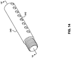
- Threaded insert 530 may be configured to receive a weight pin 540 (shown in FIGS. 14-16 ).
- Weight pin 540 may be used to organize weight portions 140.
- Weight pin 540 may be used to secure weight portions 140 in adjustable weight shot.
- weight portions 140 may be either hollow cylinders or hollow disks and weight pin 540 may pass through the hole in each weight portion 140 to keep weight portions 140 neatly stacked.
- Weight pin 540 may include slots 542 configured to receive a pin to prevent the movement of the weight portions 140 along weight pin 540.
- FIG. 17 shows an embodiment of an adjustable weight shot system 700.
- the adjustable weight shot system 700 has cap 510 and body 502.
- weight portions 600 are configured to be secured in body 502 with cap 510.
- Weight portions 600 may include a cylindrical core 602A.
- a hollow cylindrical inner weight portion 602B is configured to receive a cylindrical core 602A.
- a hollow cylindrical outer weight portion 602C is configured to receive inner cylindrical weight portion 602B.
- An athlete may use one or more weight portions 600 to adjust the total weight of the shot.
- cylindrical weight portions even when hollowed out, are typically easier to manufacture than spherical hollow hemispheres. Therefore, when the internal balance is less critical, use of cylindrical weight portions, or other shapes, may be desirable because of the reduced manufacturing costs.
Landscapes
- Health & Medical Sciences (AREA)
- General Health & Medical Sciences (AREA)
- Physical Education & Sports Medicine (AREA)
- Life Sciences & Earth Sciences (AREA)
- Biophysics (AREA)
- Orthopedic Medicine & Surgery (AREA)
- Engineering & Computer Science (AREA)
- Mechanical Engineering (AREA)
- Golf Clubs (AREA)
Abstract
Description
- Shot put is a weight throwing sport. Athletes train with the goal of throwing a heavy, typically spherical, shot as far as possible. As part of the training routine, athletes may use shots of different weights.
- The described embodiments relate generally to an adjustable weight throwing implement, for example, a shot.
- In some embodiments, an adjustable weight shot system comprises a core, an inner weight portion, an outer weight portion, a body, and a cap. The inner weight portion may be formed of two coupling hemispheres configured to receive the core in an inner weight portion cavity. The outer weight portion may be formed of two coupling hemispheres configured to receive the inner weight portion in an outer weight portion cavity. The body and cap may be configured to retain the outer weight portion in a body weight cavity defined by the body and the cap.
- In some embodiments, an adjustable weight shot system includes intermediate weight portions. Each intermediate weight portion may have two coupling hemispheres configured to receive one of a smaller intermediate weight portion and the inner weight portion in an intermediate weight portion cavity. In some embodiments, there are three intermediate weight portions. In some embodiments, an outer surface of the body is larger than an outer surface of the cap.
- In some embodiments, the body and the cap may couple in a variety of ways. For example, the body and the cap may be coupled with a threaded connection. The cap may include a cap sleeve and cap threads may be formed on the cap sleeve.
- In some embodiments, an adjustable weight shot includes a body that defines a shot cavity. The shot cavity of the adjustable weight shot may be semispherical. A first weight portion may be positioned in the shot cavity. The first weight portion may be formed of two coupling first weight portion hemispheres. The two coupling first weight portion hemispheres may define a first weight cavity. A second weight portion may be positioned in the first weight cavity and formed of two coupling second weight portion hemispheres. The two coupling second weight portion hemispheres may define a second weight cavity. The adjustable weight shot may also include weight portion key holes formed in each removable weight portion. The key holes may aid in separating the two coupling weight portion hemispheres. The key holes may be formed near the boundary of the two coupling hemispheres. In some embodiments, the hemispheres of the removable weight portions interlock using a snap-fit connection. In some embodiments, the hemispheres of the removable weight portions interlock using threads, pins, bayonet type couplings, or other interlocking devices.
- In some embodiments, an adjustable weight shot includes a cap. The body may be configured to receive the cap at an opening of the body. The cap may include a tool port configured to receive a tool. In some embodiments, the tool port includes a tool port weight disposed in the tool port.
- In some embodiments, the opening in the body has a cap seat and the cap has a cavity sleeve. The cavity sleeve is configured to engage the cap seat. In some embodiments, the shot cavity is semispherical and has a shot cavity diameter. The diameter of the cap seat may be greater than the shot cavity diameter.
- In some embodiments, an adjustable weight shot system includes a body and a cap. The cap is configured to engage an opening formed in the body. The cap may include a tool port. Additionally, an adjustable weight shot system may include a plurality of weight portion, each formed of two coupling hollow hemispheres, may be configured to receive another of the weight portion. In some embodiments, the plurality of weight portions are nested.
- The disclosure will be readily understood by the following detailed description in conjunction with the accompanying drawings, wherein like reference numerals designate like structural elements, and in which:
-
FIG. 1 shows an exploded view of an adjustable weight shot according to some embodiments. -
FIG. 2 shows the adjustable weight shot ofFIG. 1 in a collapsed view. -
FIG. 3 shows a cross section of the adjustable weight shot ofFIG. 2 taken through the line 3 - 3'. -
FIG. 4 shows a perspective view of a body for an adjustable weight shot according to some embodiments. -
FIG. 5 show a cross section of the body for the adjustable weight shot ofFIG. 4 taken through the line 5 - 5'. -
FIG. 6 shows a perspective view of a cap for an adjustable weight shot according to some embodiments. -
FIG. 7 shows a right side view of the cap for the adjustable weight shot ofFIG. 6 . -
FIG. 8 shows a cross section of the cap for the adjustable weight shot ofFIG. 7 taken at the line 8 - 8'. -
FIG. 9 shows a perspective view of a weight portion for an adjustable weight shot according to some embodiments. -
FIG. 10 shows a cross section of the weight portion for the adjustable weight shot ofFIG. 9 taken at the line 10 - 10'. -
FIG. 11 shows a cross section of a cap for an adjustable weight shot according to some embodiments. -
FIG. 12 shows a body of an adjustable weight shot according to some embodiments. -
FIG. 13 shows a cross section of the body of the adjustable shot ofFIG. 12 taken at the line 13 - 13'. -
FIG. 14 shows a perspective view of a weight pin according to some embodiments. -
FIG. 15 shows a plan view of the weight pin ofFIG. 14 . -
FIG. 16 shows a cross section of the weight pin 14 taken at the line 16 - 16'. -
FIG. 17 shows an adjustable weight shot according to some embodiments. - Reference will now be made in detail to representative embodiments illustrated in the accompanying drawings. It should be understood that the following descriptions are not intended to limit the embodiments to one preferred embodiment. To the contrary, it is intended to cover alternatives, modifications, and equivalents as can be included within the spirit and scope of the described embodiments as defined by the claims.
- The present disclosure is directed to an adjustable weight shot. The adjustable weight shot may be used during athletic training for shot put competitions.
- At a professional and Olympic level, men's shots weigh 7.260 kilograms and women's shots weight 4 kilograms. Other weights are used in other competitions or at different levels, such as college, junior, school, or masters competitions. During competition, shot put athletes throw the shot in a specified target area. The distance of the throw is measured. The goal of the competition is to throw the shot as far as possible.
- As part of the rigorous training routine for shot put, athletes may use shots of different weights to hone technique, improve muscle memory and mass, or avoid stressing muscles during warm ups. Currently, shot put athletes may rely on several shots of various weights for this complicated training regime. Practice shots may weigh less than competition shots and can be used by the athlete during training and warmup. The practice shots are often the same diameter as the competition shot to aid in developing muscle memory. Often, training implements of differing weights are made inconsistently (in finish and surface quality) and to slightly different size than the competition implements. This inconsistency in training implements can lead to reduced or inconsistent training quality, injury, or generally decreased competition performance.
- When traveling, athletes may travel with both competition and practice shots. Although men's competition shots weigh 7.260 kilograms and women's competition shots weight 4 kilograms, athletes may travel with several times that weight in practice shot when attending competitions. For example, men's practice shots may weigh 4 kilograms, 5 kilograms, and 6 kilograms and women's practice shots may weigh between from 2.5 kilograms to 6.5 kilograms. However, there are no set weight limits that an athlete may use during trainings so training weights may exceed competition weights. For example, men's practice weights may be in excess of 10 kilograms. Because athletes often travel with competition and practice shots, shot put athletes travel with a lot of weight. Additionally, because the practice shots have the same diameter as the competition shots, the numerous shots take up a large volume. The weight and volume increases travel strain and may increase travel costs, including, for example, excess weight or baggage charges.
- The current solutions to this problem have many drawbacks. Current solutions may use a shot filled with sand or another fluid like medium to change the weight of the shot. Alternatively, the weight may be changed by drilling holes in the shots. These methods are cumbersome and clumsy and can create an unbalanced shot. Of course, this may create a dangerous throwing implement because of the unbalanced shot. An unbalanced shot is dangerous to both the athlete and spectators. An unbalanced shot can create an uneven pressure on the athlete's hand, adding strain to a particular portion of the hand. Moreover, an unbalanced shot may cause the athlete to "miss" the shot causing ballistic and damaging hyperextension of the elbow and an expected trajectory of the shot. Additionally, the current solutions also often use moveable, delicate latch systems that are easily damaged during regular use. Regular use may also cause parts of such shots to become permanently stuck closed and rendered useless.
- The present disclosure is directed to an adjustable weight shot. The adjustable weight shot has a body and a cap. The cap closes a body weight cavity formed in the body. The body and the cap together may define the body weight cavity. The body may include a cap seat configured to receive the cap and body threads. The body threads are configured to engage cap threads on the cap.
- The body weight cavity is configured to receive various weight portions. Each weight portions may be formed of two or more portions. For example, each weight portions may be spherical and formed of two hemispheres. The two hemispheres may be substantially the same size, for example, each substantially half of a sphere. In some embodiments, the two hemispheres may be of unequal size. For example, one hemisphere may be substantially larger than the other hemisphere. The two hemispheres of the weight portions may be coupled together to form a weight portion. In some embodiments, the two hemispheres lock together to from the weight portion. For example, the two hemispheres may lock using a snap fit, threaded connection, pins, bayonet type couplings, or other interference fit or interlocking device techniques. Each weight portion may also include a weight portion cavity configured to receive another weight portion. That is, each weight portion may be configured to receive a weight portion and then be located in a weight portion cavity of another weight portion. In this way, the weight portions may "nest" within one another. The weight portions may also nest within the body weight cavity defined by the body and the cap.
- The cap may include a tool port configured to receive a tool. Using a tool in the tool port allows the athlete to increase the torque on the cap to more easily remove the cap from the body. Additionally, some or all of the weight portions may have key ports that help to separate portions of the weight portions from one another or help separate weight portions from each other.
- In some embodiments, for example as shown in
FIG. 1 , an adjustable weight shot 100 has abody 102. Acap 120 closes anopening 112 inbody 102. In some embodiments,cap 120 andbody 102 may be coupled using a threaded connection or other mechanical means.FIG. 1 showsbody threads 110 located inside opening 112 ofbody 102.Cap threads 130 are on acap sleeve 128 ofcap 120.Cap threads 130 are configured to engagebody threads 110 to close abody weight cavity 104. In some embodiments,body 102 defines abody weight cavity 104. In some embodiments,body 102 andcap 120 definebody weight cavity 104.FIG. 1 also shows acentral axis 300.Central axis 300 extends through the center ofbody 102 andopening 112. In some embodiments, thebody 102 and/or thecap 120 are substantially rotationally symmetrical about thecentral axis 300. -
FIG. 1 shows an exploded view of adjustable weight shot 100.Weight portions 140 are shown.Weight portions 140 are configured to be housed inbody weight cavity 104 ofbody 102. As shown inFIG. 1 , eachweight portion 140 may be formed of one or more portions, for example, two substantially equally sized portions. For example,weight portions 140 may be formed of coupling shells. As shown inFIG. 1 ,weight portions 140 are a series of coupling weight shells or hemispheres (corresponding pairs labeled as A and B).FIG. 1 shows a firstweight shell member 150 having coupling firstweight shell member 150A and firstweight shell member 150B. Firstweight shell members first weight shell 150.First weight shell 150 is hollow and defines a shell weight cavity 190 (shown inFIG. 10 ) configured to receive a secondweight shell member 152. Firstweight shell member 150 may be considered an outer weight portion because it is an outer weight portion with respect to one or more other weight portions (i.e. other weight portions are or can be placed inside it). Like firstweight shell member 150, secondweight shell member 152 is formed of two coupling hemispheres, secondweight shell members FIG. 1 shows thirdweight shell members weight shell members weight shell members weight shell member 158 may be considered an inner weight portion because it is located in the interior with respect toother weight portions 140. In some embodiments, fewer than fiveweight portions 140 may be used, such as one, two, three, or four sets ofweight portions 140. In other embodiments, more than five weighportions 140 may be used, such as six, seven, eight, nine, or tenweight portions 140. Each shell member may form weight cavities configured to receive weight portions. In some embodiments, acore 160 is located inside a weight portion, such as the innermost weight portion 140.Core 160 is also a weight portion and may be consider as an inner weight portion as well.Core 160 may be hollow or solid. In some embodiments, acore 160 may be distinguished from a weight portion in that a core is not formed from separable portions. In other embodiments, an adjustable weight shot 100 does not include acore 160. -
FIG. 2 shows adjustable weight shot 100 withcap 120 secured tobody 102 atopening 112.Cap 120 closes opening 112 ofbody 102. Atool port 122 is formed incap 120.Tool port 122 is configured to receive a tool that can be used to aid in the release ofcap 120 frombody 102. In some embodiments the tool is, for example, a hex key. In some embodiments, theopening 112 of thebody 102, thecap 120 itself, and/or thetool port 122 are substantially rotationally symmetrical about an axis, such as thecentral axis 300. In some embodiments, the junction between the opening 112 of thebody 102 and thecap 120 is substantially circular latitudinal circumference. In an embodiment, the substantially circular latitudinal circumference is between 200mm and 400mm. In some embodiments, the substantially circular latitudinal circumference is between 300mm and 350mm, for example, 320mm. -
FIG. 3 shows a cross section of adjustable weight shot 100 taken at the line 3 - 3' inFIG. 2 . For purposes of clarity, radiallyadjacent weight portions 140 are shaded differently.FIG. 3 showsweight portions 140 retained inbody weight cavity 104 defined bybody 102'scavity wall 106 and cap 120'scap cavity wall 126.Cap 120 hascap sleeve 128.Cap sleeve 128 extends intobody 102 and is seated incap seat 108.Cap seat 108 hascap ledge 109.Cap ledge 109 may form a transition betweenbody cavity wall 106 andcap seat 108.Cap ledge 109 may extend at a right angle relative tocavity wall 106 andcap seat 108. In some embodiments,cap ledge 109 may be formed at an angle other than 90° relative tocavity wall 106 andcap seat 108. For example,cap ledge 109 may be formed at a 45° angle or a 135° angle relative tocavity wall 106. In other embodiments,cap ledge 109 may be formed at an angle between 45° and 90°, or between 90° and 135°. Using the smaller angles between 45° and 90° may ease cleaning debris, such as dirt, frombody weight cavity 104. In an alternative embodiment, instead ofcap sleeve 128 extending intobody 102, the construction may differ such that a portion ofbody 102 extends into a portion ofcap 120. In some embodiments, awasher 192 may be included betweencap 120 andbody 102.Washer 192 may be made of plastic or other materials and may help sealcap 120 andbody 102. Additionally,washer 192 may prevent sticking betweencap 120 andbody 102. Other features described above could be incorporated into such an embodiment. - The
weight portions 140 illustrated inFIG. 3 are depicted as having varied radial thicknesses. In some embodiments, all weighportions 140 may have the same radial thickness. In one embodiment, the radial thicknesses of a givenweight portion 140 is substantially constant in all radial directions, which is to say theweight portion 140 is substantially symmetrical. In another embodiment, a givenweight portion 140 may not be substantially symmetrical. In some embodiments, alternatingweight portions 140 arranged radially in a nested fashion may have alternating thinner and thicker radial thicknesses. In other embodiments, a giveninner weigh portion 140 may have a thinner or a thicker radial thickness compared to a givenouter weight portion 140. Likewise in still other embodiments, a givenouter weigh portion 140 may have a thinner or a thicker radial thickness compared to a giveninner weight portion 140. In some embodiments, weight portion radial thicknesses may be between 1mm and 5mm, for example 2.5mm. -
FIG. 4 shows a perspective view ofbody 102 for adjustable weight shot 100. In some embodiments, for example, as shown inFIG. 4 , opening 112 may be smaller than a diameter of adjustable weight shot 100, and/or the circumference ofopening 112 may be smaller than the equatorial circumference of thebody 102 or shot 100.FIG. 5 shows a cross section view ofbody 102 taken at the line 5 - 5' ofFIG. 4 .Body 102 has acenter 200.Center 200 may be the geometric center of adjustable weight shot 100 whencap 120 is coupled tobody 102. In someembodiments center 200 may also be the center of mass of an assembled adjustable weight shot 100. - As shown in
FIG. 5 ,body weight cavity 104 may have acavity radius 202.Cavity radius 202 is defined as the distance betweencenter 200 and shotcavity wall 106. In some embodiments cavity radius may be between 30 mm and 50mm. For example, cavity radius may be 45mm.Center 200 may also be used to define a shot radius. A shown inFIG. 5 , shotradius 208 is the radius of the shot when assembled and also defines the radius of curvature of the outer surfaces ofshot 102 andcap 120. In some embodiment shotradius 208 may be between 50 and 80mm. In some embodiments, shotradius 208 may be 65.22mm, giving the adjustable weight shot a diameter of 130.44mm.Shot radius 208 may be governed by athletic standards such as those developed under the International Association of Athletics Federations (IAAF). -
FIG. 5 also shows acap seat width 204 and a cap threadedwidth 206. In some embodiments, thecap seat width 204 and the cap threadedwidth 206 may be substantially the same, while in other embodiments they will differ. In some embodiments, cap threadedwidth 206 may be between approximately 12mm and 20mm. For example, cap threadedwidth 206 may be approximately 15mm. In some embodiments,cap seat width 204 may be between 15mm and 20mm. In some embodiments,seat cap width 204 may be 18mm.Opening radius 214 is a distance betweenopening 112 andcenter 200 ofbody 102.Cap seat width 204 may be greater than twicecavity radius 202. -
FIGS. 6 and7 shows cap 120 withcap cavity 124.Cap cavity 124 is bounded by acap cavity wall 126. Acap sleeve 128 surroundscap cavity 124. In some embodiments,cap sleeve 128 is substantially cylindrical. An upper portion ofcap 120 hascap screw threads 130. In one embodiment, when considered in cross section, thecap 120 has five threads. In other embodiments, the cap may have three, four, six, or seven threads.Cap threads 130 are configured to engagebody threads 110 by screwing into them to securecap 120 tobody 102. -
FIG. 8 is a cross section ofcap 120 taken at the line 8 - 8' ofFIG. 7 .FIG. 8 shows cap 120 withtool port 122. The shape oftool port 122 may depend on both the tool that tool port is configured to receive and manufacturing considerations. For example, as shown inFIG. 8 ,tool port 122 may have a hexagonal shape. The hexagonal shape oftool port 122 is configured to mate with a tool (not shown) having a hexagonal shape. For example, the tool may be an standard sized hex key, also known as an Allen wrench. -
Tool port 122 may also include atool port weight 132 located within the tool port, such as at the bottom oftool port 122 as depicted inFIG. 8 . In some embodiments,tool port weight 132 may be a liner or a filling applied totool port 122.Tool port weight 132 is configured to counter balance the amount of weight removed from adjustable weight shot 100 whentool port 122 is formed. For this reason, in some embodiments,tool port weight 132 may be made of a material having a higher density than the material that makes upcap 120. In some embodiments,tool port weight 132 has a weight equal to approximately the weight of the material removed to fromtool port 122. In some embodiments, a tool port plug (not shown) may be used to plugtool port 122. In some embodiments,tool port 122 may have a threaded top or other means to secure the tool port plug totool port 122. In some embodiments, the tool port plug may have a key hole, which may be a configured to receive the edge of a coin, that can be used to loosen tool port plug fromtool port 122. -
FIG. 9 shows anexemplary weight portion 140.Weight portion 140 is formed of two weight portion hemispheres 150. While the weight portion ofFIG. 9 is depicted as having two substantially equalhalf portion hemispheres 150, in some embodiments, one portion may be larger than the other.Weight portions 140 may have a weight portionkey port 180 located in or near aseam 174. For example,key port 180 may be nearseam 174 when itkey port 180 is onseam 174 or whenkey port 180 is adjacent tokey port 180. In some embodiments,key port 180 may be located further fromseam 174.Seam 174 is the division between the two weight portion hemispheres. In some embodiments where one of the two parts ofweight portion 140 is larger than the other part, theseam 174 may not divide theweigh portion 140 approximately in half.Key port 180 may be used to help an athlete separate twoweight portion 140 parts, such ashemispheres 150. -
FIG. 10 shows a cross section of aweight portion 140 taken through the line 10 - 10' shown inFIG. 9 .FIG. 10 shows twohemispheres seam 174.Hemispheres seam 174. For example, as shown inFIG. 10 ,hemisphere 150A may have astep 170 extending from the edge of the hemisphere which is configured to mate with acorresponding recess 172 formed in the edge ofhemisphere 150B.Hemispheres FIG. 10 or by other means. For example,hemispheres hemispheres weight portion cavity 190 is formed inside ofweight portion 140 whenhemispheres weight portion 140 may not be formed from substantially equal hemispheres, but may be formed from two or more unequally sized portions. - The total weight of adjustable weight shot 100 can be varied by adding to or removing
weight portions 140 from adjustable weight shot 100, or by usingweight portions 140 of materials having different volumes, weights, and/or densities. In some embodiments, aweight portion 140 is made from the same material asbody 102,cap 120, and/orcore 160. In other embodiments, one or more of anyweight portions 140, thebody 102, thecap 120, and thecore 160 may be made of different materials having different volumes, weights, and/or densities. - The exploded view of adjustable weight shot 100 in
FIG. 1 shows adjustable weight shot 100 with severalnesting weight portions 140. At the center iscore 160.Core 160 is insideweight portion 158, which is formed fromhemispheres Weight portion 158 is insideweight port 156, which is formed fromhemispheres Weight portion 156 is insideweight port 154, which is formed fromhemispheres Weight portion 154 is insideweight port 152, which is formed fromhemispheres weight portion 150, which is formed fromhemispheres weight portions 158 through 152, andcore 160. In this manner,weight portions 140 nest inside each other.Core 160 may be described as an inner weight portion andweight portion 150 may be an outer weight portion. Inner andouter weight portions 140 either may be adjacent to one other or may be separated by anotherweight portion 140. In some embodiments there are substantially no gaps betweenadjacent weight portions 140, whereas in other embodiments there are gaps betweenadjacent weight portions 140. - Balance may be an important consideration of adjustable weight shot 100. The balance of adjustable weight shot 100 can be considered in two ways. First, the balance of adjustable weight shot 100 can be considered as the stability of adjustable weight shot 100 and portions thereof during the throw.
Weight portions 140 should not significantly shift inside adjustable weight shot 100 during the throw. Ifweight portions 140 do significantly shift during the throw, the athlete could be knocked off balance or the throw's trajectory could be negatively affected. Second, the balance of adjustable weight shot 100 can be considered as an even distribution of weight around acenter 200 of adjustable weight portion, as depicted inFIG. 5 . In some embodiments, weight should be substantially evenly distributed around thecenter 200. - Stability balance means that the tolerances of the components of adjustable weight shot 100 should be tight. For example, a coarse threading may be used for
cap threads 130 andbody threads 110. In some embodiments, the threading may be an M96x2.5 thread. Corse threads may reduce the shifting ofcap 120 relative tobody 102 during a throw or normal use. Additionally,weight portions 140 should be tightly secured in adjustable weight shot 100. Whenweight portions 140 are nested, such as is shown inFIGS. 1 and3 , eachweight portion 140 may fit tightly or snuggly in eachouter weight portion 140's weightportion weight cavity 190. For example, manufacturing tolerance for the interior and exterior diameters of weight portions 140 (when weight portions are spherical) may be between 0.5 mm and 0 mm, between 0.5 mm and 0.1 mm, between 0.25 mm and 0 mm, between 0.25 mm and 0.1 mm, between 0.1 mm and 0 mm, or the tolerance may be approximately 0.1 mm. - Adjustable weight shot 100 may maintain balance using several features. In some embodiments,
weight portions 140 are spherical. Usingspherical weight portions 140 may give a general uniform density at a given distance fromcenter 200 of adjustable weight shot 100. As mentioned above, whentool port 122 is formed incap 120, atool port weight 132 may be added totool port 122 to compensate for the amount of mass absent from the volume oftool port 122. In some embodiments, additional weight portions may be added to certain portions of adjustable weight shot 100 to add any necessary balance to adjustable weight shot 100. - Although
weight portions 140 are shown in the figures as spherical, other shapes are possible. For example, weight portions could be non-spherical such as cylindrical, ellipsoidal, disc-shaped, or ring shaped. In some embodiments the shape of the weight portion may be dictated by the use of the adjustable weight shot. For example, when an adjustable weight shot 100 is used as a hammer, in the context of the hammer throw sport, the internal balance of the shot may be less important because the weight is swung around the central pivot (i.e., the athlete throwing the hammer). The form, specifically the shape and weighting characteristics, of adjustable weight shot 100 may be different when used as a hammer. For example, the adjustable weight shot 100 may include a swivel attached to adjustable weight shot 100. The swivel may attach to a wire for the athlete to hold. In some embodiments,cylindrical weight potions 140 may be hollow cylinders open on each end in which additional cylinders may be inserted.Cylindrical weight portions 140, even when hollowed out, are typically easier to manufacture than spherical hollow hemispheres. Therefore, when the internal balance is less critical, use ofcylindrical weight portions 140, or other shapes, may be desirable because of the reduced manufacturing costs. - Components of adjustable weight shot 100 may be made of a variety of materials. In some embodiments, all components of adjustable weight shot 100 are made of the same material. In some embodiments, different components of adjustable weight shot 100 are made of different materials. The use of different materials for different components of adjustable weight shot 100 may give the athlete more flexibility in choosing the weight amount for the specific training. In some embodiments,
body 102,cap 120, orweight portions 140 are formed of aluminum, cast iron, mild steels, ferrous steels, stainless steels, tungsten, brass, bronze, other alloys, ceramics, natural stones, plastics, rubbers, or a granular load such as sand or shot load. - An adjustable weight shot 100 having
nesting weight portions 140 made from different materials gives an athlete significant flexibility in selecting the amount of weight for each shot. For example,body 102 andcap 120 may be made of mild steel and have a weight of approximately 2 kilograms. Anouter weight portion 140 may fit snuggly insidebody 102'sbody weight cavity 104.Outer weight portion 140 may be made of a hard rubber and weight 0.5 kilograms. Aninner weight portion 140 may fit snuggly insideouter weight portion 140'sweight cavity 190.Inner weight portion 140 is formed of aluminum and weighs 1 kilogram. Altogether, the total weight of adjustable weight shot 100 may be approximately 3.5 kilograms. - Adjustable weight shot 100 may experience stresses during use. The largest stress that adjustable weight shot 100 may experience during use is the impact with the ground, or other object, after adjustable weight shot 100 is thrown. The large impact forces experienced at impact may cause certain components of adjustable weight shot 100 to become wedged tightly together. In some embodiments, adjustable weight shot 100 minimizes the risks of overtightening. Adjustable weight shot 100 may use
cap 120 that has a smaller outer surface area thanbody 102. This creates a seam betweencap 120 andbody 102 that is shorter than if theseam 174 were located closer to the largest latitudinal circumference of theshot 100. Since overtightening is more likely to occur when an impact occurs at theseam 174, reducing the length and size of theseam 174 may be important to reducing overtightening events. The outer surface area ofbody 102 andcap 120 when described in this context means the exposed surface of each whenbody 102 andcap 120 are assembled into adjustable weight shot 100. For example,FIG. 2 shows the exposed surfaces of each ofbody 102 andcap 120. - Should overtightening occur, an athlete can use a tool key in
tool port 122 to increase the torque oncap 120 relative tobody 102 to releasecap 120 frombody 102. Additionally,key port 180 inweight portions 140 may function as hinge ports to wedgeweight portions 140 apart. In some embodiments,key port 180 may aid in the manufacturing process, such as, aiding in applying painting or electroplating. For example,weight portions 140 may be able to hang fromkey port 180 during the manufacturing process. -
FIGS. 11-16 show an adjustable weight shot system according to some embodiments. Adjustable weight shot may be used, for example, during a hammer throw competition. Adjustable weight shot includes a cap 520 (shown in cross section inFIG. 11 with a cross section taken at the line 8 - 8' ofFIG. 7 ) and a body 502 (shown inFIG. 12 ). In some embodiments,cap 520 is configured to engage with andclose opening 512 inbody 502.FIG. 13 shows a cross section ofbody 502 taken at the line 13 - 13'.Body 502 has acap seat 508 configured to receive a portion ofcap 520. As shown inFIG. 13 ,body 502 may have one or more levels ofweight seats 509 configured to receiveweight portions 140. As discussed above,weight portions 140 may be formed in different shapes. The shape and configuration ofweight seats 509 may change depending on the shape and configuration ofweight portions 140. For example,FIG. 13 showsweight seats 509 that may be well suited to receivecylindrical weight portions 140.Weight seat 509 may located opposite ofopening 512. In some embodiments,body 502 may also include one or more attachment points 510 on theexterior portion body 502. Attachment points 510 may be configured to engage additional members. For example,FIG. 13 shows attachment point 510 as a threaded member configured to receive a threaded attachment. In this and other embodiments,attachment point 510 may be configure to receive a member to aid that athlete in practicing the hammer throw. - In some embodiments, a threaded
insert 530 may be on the interior side of adjustable weight shot. For example, threadedinsert 530 may be on the interior side ofcap 520, as shown inFIG. 11 . Threadedinsert 530 may be configured to receive a weight pin 540 (shown inFIGS. 14-16 ).Weight pin 540 may be used to organizeweight portions 140.Weight pin 540 may be used to secureweight portions 140 in adjustable weight shot. For example,weight portions 140 may be either hollow cylinders or hollow disks andweight pin 540 may pass through the hole in eachweight portion 140 to keepweight portions 140 neatly stacked.Weight pin 540 may includeslots 542 configured to receive a pin to prevent the movement of theweight portions 140 alongweight pin 540. -
FIG. 17 shows an embodiment of an adjustable weight shotsystem 700. The adjustable weight shotsystem 700 hascap 510 andbody 502. In some embodiments,weight portions 600 are configured to be secured inbody 502 withcap 510.Weight portions 600 may include acylindrical core 602A. A hollow cylindricalinner weight portion 602B is configured to receive acylindrical core 602A. A hollow cylindricalouter weight portion 602C is configured to receive innercylindrical weight portion 602B. An athlete may use one ormore weight portions 600 to adjust the total weight of the shot. As previously noted, cylindrical weight portions, even when hollowed out, are typically easier to manufacture than spherical hollow hemispheres. Therefore, when the internal balance is less critical, use of cylindrical weight portions, or other shapes, may be desirable because of the reduced manufacturing costs. - The foregoing descriptions of the specific embodiments described herein are presented for purposes of illustration and description. These exemplary embodiments are not intended to be exhaustive or to limit the embodiments to the precise forms disclosed. All specific details described are not required in order to practice the described embodiments.
- It will be apparent to one of ordinary skill in the art that many modifications and variations are possible in view of the above teachings, and that by applying knowledge within the skill of the art, one may readily modify and/or adapt for various applications such specific embodiments, without undue experimentation, without departing from the general concept of the present invention. Such adaptations and modifications are intended to be within the meaning and range of equivalents of the disclosed embodiments, based on the teaching and guidance presented herein.
- The Detailed Description section is intended to be used to interpret the claims. The Summary and Abstract sections may set forth one or more but not all exemplary embodiments of the present invention as contemplated by the inventor(s), and thus, are not intended to limit the present invention and the claims.
- The phraseology or terminology used herein is for the purpose of description and not limitation, such that the terminology or phraseology of the present specification is to be interpreted by the skilled artisan.
- The breadth and scope of the present invention(s) should not be limited by any of the above-described exemplary embodiments, but should be defined only in accordance with the claims and their equivalents.
- In accordance with the invention disclosed therein, the following preferred embodiments are disclosed:
- 1. An adjustable weight shot system comprising:
- a core;
- an inner weight portion comprising two coupling hemispheres configured to receive the core in an inner weight portion cavity;
- an outer weight portion comprising two coupling hemispheres configured to receive the inner weight portion in an outer weight portion cavity; and
- a body and a cap coupled to the body, wherein the body and cap are configured to retain the outer weight portion in a body weight cavity defined by the body and the cap.
- 2. The adjustable weight shot system of
embodiment 1, further comprising:
one or more intermediate weight portions, each intermediate weight portion comprising two coupling hemispheres defining an intermediate weight portion cavity. - 3. The adjustable weight shot system of embodiment 2, wherein the number of intermediate weight portions is three.
- 4. The adjustable weight shot system of
embodiment 1, wherein an outer surface area of the body is larger than an outer surface area of the cap. - 5. The adjustable weight shot system of
embodiment 1, wherein the body and cap are configured to be coupled using a threaded connection. - 6. The adjustable weight shot system of
embodiment 1,- the cap comprising a cap sleeve; and
- the cap sleeve comprising cap threads.
- 7. An adjustable weight shot comprising:
- a body defining a shot cavity
- a weight portion configured to be positioned in the shot cavity and comprising two coupling weight portion hemispheres, the two coupling weight portion hemispheres defining a weight cavity.
- 8. The adjustable weight shot of embodiment 7, further comprising:
- a cap, wherein the body is configured to receive the cap at an opening of the body.
- 9. The adjustable weight shot of embodiment 7, wherein the weight portion is a first weight portion, the weight portion hemispheres are first weight portion hemispheres, and the weight cavities are first weight cavities, further comprising:
a second weight portion configured to be positioned in the first weight cavity and comprising two coupling second weight portion hemispheres, the two coupling weight portion hemispheres defining a second weight cavity. - 10. The adjustable weight shot of embodiment 7, the weight portion further comprising a weight portion key hole.
- 11. The adjustable weight shot of
embodiment 10, wherein the weight portion key hole is formed near a boundary of the two coupling weight portion hemispheres. - 12. The adjustable weight shot of embodiment 7, wherein the weight portion hemispheres of the removable weight portion are configured to couple using a snap-fit connection.
- 13. The adjustable weight shot of embodiment 7, wherein the shot cavity is semispherical.
- 14. The adjustable weight shot of
embodiment 8, the cap comprising a tool port. - 15. The adjustable weight shot of embodiment 14, the tool port comprising a tool port weight.
- 16. The adjustable weight shot of
embodiment 8,- the body comprising a cap seat extending radially inward from the opening; and
- the cap comprising a cavity sleeve, wherein the cavity sleeve is configured to engage the cap seat.
- 17. The adjustable weight shot of
embodiment 16,- wherein the shot cavity is semispherical and has a shot cavity radius,
- wherein the cap seat has a cap seat diameter, and
- wherein the cap seat diameter is greater than the shot cavity diameter.
- 18. An adjustable weight shot system comprising:
- a body and a cap, the cap configured to engage an opening formed in the body; and
- a plurality of weight portions, each weight portion comprising two coupling hollow hemispheres,
- wherein the plurality of weight portions are configured to nest inside the body.
- 19. The adjustable weight shot system of embodiment 18, wherein the plurality of weight portions is five weight portions.
- 20. The adjustable weight shot system of embodiment 19, the cap comprising a tool port formed on an exterior surface of the cap.
- 21. An adjustable weight shot system comprising:
- a body and a cap, the cap configured to engage an opening formed in the body; and
- a plurality of cylindrical weight portions,
- wherein the plurality of weight portions are configured to nest inside the body.
- 22. An adjustable weight shot system comprising:
- a cylindrical core;
- a hollow cylindrical inner weight portion configured to receive the cylindrical core;
- a hollow cylindrical outer weight portion configured to receive the hollow cylindrical inner weight portion;
- a body configured to receive the hollow cylindrical outer weight portion; and
- a cap;
wherein the cap and body have a spherical shape when the cap is secured to the body. - 23. The adjustable weight shot system of embodiment 22, wherein the cap comprises a tool port.
- 24. The adjustable weight shot system of embodiment 22, wherein the body further comprises a recess configured to receive a portion of the cylindrical core.
Claims (15)
- An adjustable weight shot system comprising:- a core;- an inner weight portion comprising two coupling hemispheres configured to receive the core in an inner weight portion cavity;- an outer weight portion comprising two coupling hemispheres configured to receive the inner weight portion in an outer weight portion cavity; and- a body and a cap coupled to the body, wherein the body and cap are configured to retain the outer weight portion in a body weight cavity defined by the body and the cap.
- The adjustable weight shot system of claim 1, further comprising:
one or more intermediate weight portions, each intermediate weight portion comprising two coupling hemispheres defining an intermediate weight portion cavity, preferably wherein the number of intermediate weight portions is three. - The adjustable weight shot system of claim 1 or 2, wherein an outer surface area of the body is larger than an outer surface area of the cap and/or wherein the body and cap are configured to be coupled using a threaded connection.
- The adjustable weight shot system of any of the preceding claims,- the cap comprising a cap sleeve; and- the cap sleeve comprising cap threads.
- An adjustable weight shot comprising:- a body defining a shot cavity,- a weight portion configured to be positioned in the shot cavity and comprising two coupling weight portion hemispheres, the two coupling weight portion hemispheres defining a weight cavity, and- preferably a cap, wherein the body is configured to receive the cap at an opening of the body.
- The adjustable weight shot of claim 5, wherein the weight portion is a first weight portion, the weight portion hemispheres are first weight portion hemispheres, and the weight cavities are first weight cavities, further comprising:
a second weight portion configured to be positioned in the first weight cavity and comprising two coupling second weight portion hemispheres, the two coupling weight portion hemispheres defining a second weight cavity. - The adjustable weight shot of claim 5 or 6, wherein the weight portion further comprises a weight portion key hole, preferably wherein the weight portion key hole is formed near a boundary of the two coupling weight portion hemispheres,
and/or wherein
the weight portion hemispheres of the removable weight portion are configured to couple using a snap-fit connection.. - The adjustable weight shot of any of claims 5 to 7, wherein the shot cavity is semispherical
and/or wherein
the cap comprises a tool port, the tool port preferably comprising a tool port weight. - The adjustable weight shot of any of claims 5 to 8,- the body comprising a cap seat extending radially inward from the opening; and- the cap comprising a cavity sleeve,- wherein the cavity sleeve is configured to engage the cap seat.
- The adjustable weight shot of claim 9,- wherein the shot cavity is semispherical and has a shot cavity radius,- wherein the cap seat has a cap seat diameter, and- wherein the cap seat diameter is greater than the shot cavity diameter.
- An adjustable weight shot system comprising:- a body and a cap, the cap configured to engage an opening formed in the body; and- a plurality of weight portions, each weight portion comprising two coupling hollow hemispheres,- wherein the plurality of weight portions are configured to nest inside the body.
- The adjustable weight shot system of claim 11, wherein the plurality of weight portions is five weight portions
and/or wherein
the cap comprises a tool port formed on an exterior surface of the cap. - An adjustable weight shot system comprising:- a body and a cap, the cap configured to engage an opening formed in the body; and- a plurality of cylindrical weight portions,- wherein the plurality of weight portions are configured to nest inside the body.
- An adjustable weight shot system comprising:- a cylindrical core;- a hollow cylindrical inner weight portion configured to receive the cylindrical core;- a hollow cylindrical outer weight portion configured to receive the hollow cylindrical inner weight portion;- a body configured to receive the hollow cylindrical outer weight portion; and- a cap;- wherein the cap is configured to retain the outer weight portion in the body, and- wherein the cap and body have a spherical shape when the cap is secured to the body.
- The adjustable weight shot system of claim 14, wherein the cap comprises a tool port
and/or wherein
the body further comprises a recess configured to receive a portion of the cylindrical core.
Applications Claiming Priority (2)
| Application Number | Priority Date | Filing Date | Title |
|---|---|---|---|
| US201962809130P | 2019-02-22 | 2019-02-22 | |
| US16/795,983 US20200269107A1 (en) | 2019-02-22 | 2020-02-20 | Adjustable weight shot |
Publications (1)
| Publication Number | Publication Date |
|---|---|
| EP3711825A1 true EP3711825A1 (en) | 2020-09-23 |
Family
ID=69740109
Family Applications (1)
| Application Number | Title | Priority Date | Filing Date |
|---|---|---|---|
| EP20158666.6A Withdrawn EP3711825A1 (en) | 2019-02-22 | 2020-02-21 | Adjustable weight shot |
Country Status (2)
| Country | Link |
|---|---|
| US (1) | US20200269107A1 (en) |
| EP (1) | EP3711825A1 (en) |
Families Citing this family (3)
| Publication number | Priority date | Publication date | Assignee | Title |
|---|---|---|---|---|
| US11724207B2 (en) * | 2019-02-26 | 2023-08-15 | Flambeau, Inc. | Adjustable counterweight for a rotatable performance device |
| EP4405061A4 (en) * | 2021-09-22 | 2025-06-25 | Alexander Bui | Multi-modal portable exercise equipment |
| WO2026029717A1 (en) | 2024-07-29 | 2026-02-05 | Agrebi Brahim | Ballistic training and rehabilitation device for shoulders and arms, providing instant throwing variables feedback |
Citations (4)
| Publication number | Priority date | Publication date | Assignee | Title |
|---|---|---|---|---|
| US1986687A (en) * | 1934-07-09 | 1935-01-01 | Tenison Samuel Alfred | Shot |
| US6387022B1 (en) * | 1999-08-26 | 2002-05-14 | Robert S. Smith | Adjustable weight medicine ball with handle |
| CN203989762U (en) * | 2014-07-24 | 2014-12-10 | 江苏海事职业技术学院 | A kind of training shot of adjustable weight |
| US20160256730A1 (en) * | 2015-03-05 | 2016-09-08 | Mike Bartos | Adjustable weight workout stone |
Family Cites Families (9)
| Publication number | Priority date | Publication date | Assignee | Title |
|---|---|---|---|---|
| CA1285297C (en) * | 1988-03-30 | 1991-06-25 | Gordon K. Russell | Inflatable ball |
| US5335907A (en) * | 1988-06-13 | 1994-08-09 | Donald Spector | Variable weight playball |
| US7381157B2 (en) * | 2005-12-13 | 2008-06-03 | Diani, Llc | Exercise device and method |
| US7491157B1 (en) * | 2008-03-03 | 2009-02-17 | Asia Regent Limited | Weight-adjustable dumbbell |
| US8568280B2 (en) * | 2010-08-25 | 2013-10-29 | Ernest Richard MENDOZA | Separable weight adjustable medicine ball |
| WO2014124055A2 (en) * | 2013-02-06 | 2014-08-14 | AryaBall, LLC | Multi-sport ball, multi-sport apparatus, and computing device, software and methods for indicating multiple sports |
| US9352180B2 (en) * | 2014-10-20 | 2016-05-31 | Gproducts, Llc | Variable weight medicine ball |
| US20190076715A1 (en) * | 2017-09-12 | 2019-03-14 | Derek Denton | Variable weight shot put assembly |
| US10561915B1 (en) * | 2019-01-29 | 2020-02-18 | Michael Z. McGuiness | Pitch training device |
-
2020
- 2020-02-20 US US16/795,983 patent/US20200269107A1/en not_active Abandoned
- 2020-02-21 EP EP20158666.6A patent/EP3711825A1/en not_active Withdrawn
Patent Citations (4)
| Publication number | Priority date | Publication date | Assignee | Title |
|---|---|---|---|---|
| US1986687A (en) * | 1934-07-09 | 1935-01-01 | Tenison Samuel Alfred | Shot |
| US6387022B1 (en) * | 1999-08-26 | 2002-05-14 | Robert S. Smith | Adjustable weight medicine ball with handle |
| CN203989762U (en) * | 2014-07-24 | 2014-12-10 | 江苏海事职业技术学院 | A kind of training shot of adjustable weight |
| US20160256730A1 (en) * | 2015-03-05 | 2016-09-08 | Mike Bartos | Adjustable weight workout stone |
Also Published As
| Publication number | Publication date |
|---|---|
| US20200269107A1 (en) | 2020-08-27 |
Similar Documents
| Publication | Publication Date | Title |
|---|---|---|
| US20200269107A1 (en) | Adjustable weight shot | |
| US7048678B2 (en) | Dumbbell having interlocking components | |
| US6387022B1 (en) | Adjustable weight medicine ball with handle | |
| US4453710A (en) | Dumbbell | |
| US4076236A (en) | Bar-bell type exercising device | |
| US9388842B2 (en) | Weight screw | |
| US6120420A (en) | Exercise device | |
| US9682268B2 (en) | Dead blow weight control system | |
| US12070645B2 (en) | Adjustable and fillable weight plate | |
| US5603666A (en) | Golf putter | |
| US10561915B1 (en) | Pitch training device | |
| US9352180B2 (en) | Variable weight medicine ball | |
| US20240023719A1 (en) | Submergible Stool | |
| GB2151493A (en) | Barbell with weight clamping means | |
| US20250041675A1 (en) | Pickleball apparatus | |
| US20160256730A1 (en) | Adjustable weight workout stone | |
| JP2024503240A (en) | Interchangeable golf club grips with shaft attachment system | |
| US4905992A (en) | Collapsible weight system | |
| US6089998A (en) | Center element for hockey puck | |
| US20070298938A1 (en) | Exercise device construction | |
| US20030224867A1 (en) | Golf swing training club with adjustable weight | |
| US5776004A (en) | Putting practice device | |
| US3400929A (en) | Bowling ball with replaceable grip and adjustable weight | |
| US5522780A (en) | Discus for throwing | |
| CN101099884A (en) | Adjustable dumbbell system |
Legal Events
| Date | Code | Title | Description |
|---|---|---|---|
| PUAI | Public reference made under article 153(3) epc to a published international application that has entered the european phase |
Free format text: ORIGINAL CODE: 0009012 |
|
| STAA | Information on the status of an ep patent application or granted ep patent |
Free format text: STATUS: THE APPLICATION HAS BEEN PUBLISHED |
|
| AK | Designated contracting states |
Kind code of ref document: A1 Designated state(s): AL AT BE BG CH CY CZ DE DK EE ES FI FR GB GR HR HU IE IS IT LI LT LU LV MC MK MT NL NO PL PT RO RS SE SI SK SM TR |
|
| AX | Request for extension of the european patent |
Extension state: BA ME |
|
| STAA | Information on the status of an ep patent application or granted ep patent |
Free format text: STATUS: REQUEST FOR EXAMINATION WAS MADE |
|
| 17P | Request for examination filed |
Effective date: 20201223 |
|
| RBV | Designated contracting states (corrected) |
Designated state(s): AL AT BE BG CH CY CZ DE DK EE ES FI FR GB GR HR HU IE IS IT LI LT LU LV MC MK MT NL NO PL PT RO RS SE SI SK SM TR |
|
| GRAP | Despatch of communication of intention to grant a patent |
Free format text: ORIGINAL CODE: EPIDOSNIGR1 |
|
| STAA | Information on the status of an ep patent application or granted ep patent |
Free format text: STATUS: GRANT OF PATENT IS INTENDED |
|
| INTG | Intention to grant announced |
Effective date: 20210526 |
|
| STAA | Information on the status of an ep patent application or granted ep patent |
Free format text: STATUS: THE APPLICATION IS DEEMED TO BE WITHDRAWN |
|
| 18D | Application deemed to be withdrawn |
Effective date: 20211006 |