EP3711631A1 - Case bracket and electric equipment - Google Patents
Case bracket and electric equipment Download PDFInfo
- Publication number
- EP3711631A1 EP3711631A1 EP20155034.0A EP20155034A EP3711631A1 EP 3711631 A1 EP3711631 A1 EP 3711631A1 EP 20155034 A EP20155034 A EP 20155034A EP 3711631 A1 EP3711631 A1 EP 3711631A1
- Authority
- EP
- European Patent Office
- Prior art keywords
- case
- case bracket
- mounting portion
- main body
- body frame
- Prior art date
- Legal status (The legal status is an assumption and is not a legal conclusion. Google has not performed a legal analysis and makes no representation as to the accuracy of the status listed.)
- Pending
Links
Images





Classifications
-
- H—ELECTRICITY
- H05—ELECTRIC TECHNIQUES NOT OTHERWISE PROVIDED FOR
- H05K—PRINTED CIRCUITS; CASINGS OR CONSTRUCTIONAL DETAILS OF ELECTRIC APPARATUS; MANUFACTURE OF ASSEMBLAGES OF ELECTRICAL COMPONENTS
- H05K5/00—Casings, cabinets or drawers for electric apparatus
- H05K5/02—Details
- H05K5/0204—Mounting supporting structures on the outside of casings
-
- A—HUMAN NECESSITIES
- A47—FURNITURE; DOMESTIC ARTICLES OR APPLIANCES; COFFEE MILLS; SPICE MILLS; SUCTION CLEANERS IN GENERAL
- A47B—TABLES; DESKS; OFFICE FURNITURE; CABINETS; DRAWERS; GENERAL DETAILS OF FURNITURE
- A47B96/00—Details of cabinets, racks or shelf units not covered by a single one of groups A47B43/00 - A47B95/00; General details of furniture
- A47B96/06—Brackets or similar supporting means for cabinets, racks or shelves
-
- H—ELECTRICITY
- H05—ELECTRIC TECHNIQUES NOT OTHERWISE PROVIDED FOR
- H05K—PRINTED CIRCUITS; CASINGS OR CONSTRUCTIONAL DETAILS OF ELECTRIC APPARATUS; MANUFACTURE OF ASSEMBLAGES OF ELECTRICAL COMPONENTS
- H05K5/00—Casings, cabinets or drawers for electric apparatus
- H05K5/02—Details
- H05K5/0217—Mechanical details of casings
- H05K5/023—Handles; Grips
-
- H—ELECTRICITY
- H05—ELECTRIC TECHNIQUES NOT OTHERWISE PROVIDED FOR
- H05K—PRINTED CIRCUITS; CASINGS OR CONSTRUCTIONAL DETAILS OF ELECTRIC APPARATUS; MANUFACTURE OF ASSEMBLAGES OF ELECTRICAL COMPONENTS
- H05K5/00—Casings, cabinets or drawers for electric apparatus
- H05K5/02—Details
- H05K5/0217—Mechanical details of casings
- H05K5/0234—Feet; Stands; Pedestals, e.g. wheels for moving casing on floor
-
- H—ELECTRICITY
- H05—ELECTRIC TECHNIQUES NOT OTHERWISE PROVIDED FOR
- H05K—PRINTED CIRCUITS; CASINGS OR CONSTRUCTIONAL DETAILS OF ELECTRIC APPARATUS; MANUFACTURE OF ASSEMBLAGES OF ELECTRICAL COMPONENTS
- H05K7/00—Constructional details common to different types of electric apparatus
- H05K7/14—Mounting supporting structure in casing or on frame or rack
- H05K7/1422—Printed circuit boards receptacles, e.g. stacked structures, electronic circuit modules or box like frames
- H05K7/1427—Housings
- H05K7/1432—Housings specially adapted for power drive units or power converters
-
- H—ELECTRICITY
- H02—GENERATION; CONVERSION OR DISTRIBUTION OF ELECTRIC POWER
- H02S—GENERATION OF ELECTRIC POWER BY CONVERSION OF INFRARED RADIATION, VISIBLE LIGHT OR ULTRAVIOLET LIGHT, e.g. USING PHOTOVOLTAIC [PV] MODULES
- H02S40/00—Components or accessories in combination with PV modules, not provided for in groups H02S10/00 - H02S30/00
- H02S40/30—Electrical components
-
- Y—GENERAL TAGGING OF NEW TECHNOLOGICAL DEVELOPMENTS; GENERAL TAGGING OF CROSS-SECTIONAL TECHNOLOGIES SPANNING OVER SEVERAL SECTIONS OF THE IPC; TECHNICAL SUBJECTS COVERED BY FORMER USPC CROSS-REFERENCE ART COLLECTIONS [XRACs] AND DIGESTS
- Y02—TECHNOLOGIES OR APPLICATIONS FOR MITIGATION OR ADAPTATION AGAINST CLIMATE CHANGE
- Y02E—REDUCTION OF GREENHOUSE GAS [GHG] EMISSIONS, RELATED TO ENERGY GENERATION, TRANSMISSION OR DISTRIBUTION
- Y02E10/00—Energy generation through renewable energy sources
- Y02E10/50—Photovoltaic [PV] energy
Definitions
- the present application relates to the technical field of mounting brackets, and in particular to a case bracket.
- the present application also relates to an electrical equipment having the case bracket
- An electrical structure is usually mounted in a case body of a case, such as an inverter case.
- a handle is usually provided on a side wall of the case for facilitating staff carrying.
- a hanging device is usually provided on a rear wall of the case. The inverter is connected to a wall hanging plate through the hanging device, so as to achieve the hanging mounting of the inverter.
- mounting locations are provided on a side and a rear wall of the case, and a handle and a hanging device are separately mounted by the staff.
- a case bracket is provided by the present application for improving the mounting efficiency of the case bracket.
- a case having the case bracket is further provided by the present application.
- the case bracket provided according to the present application includes a main body frame, a handle portion provided on the main body frame, and a hanging device provided on the main body frame.
- the main body frame includes a mounting portion for fixedly connecting to a case body.
- the handle portion is a handle protrusion protruding outward from the mounting portion, and the handle protrusion and the mounting portion are formed as an integral structure.
- the handle portion is an operation hole provided in the mounting portion.
- the operation hole is provided along a length direction of the mounting portion.
- the operation hole is an oblong hole.
- the main body frame further includes two support legs fixedly connected to the mounting portion, the two support legs are arranged along the length direction of the mounting portion, two hanging devices are provided, and the two hanging devices are respectively mounted on the support legs.
- the hanging device is a hanging protrusion or a hanging recess configured to allow the case body to be hung up.
- the hanging device and the support leg are formed as an integral structure.
- an end of the hanging device facing away from the mounting portion is a support surface, and the support surface protrudes outward from a side of the case.
- the hanging device is detachably connected to the support leg.
- the main body frame further includes a reinforcing rib plate having two ends connected to the support leg and the mounting portion, respectively.
- An electrical equipment includes a case body and a case bracket, and the case bracket is fixedly connected to the case body and configured to achieve the hanging of the case body, and the case bracket is the case bracket according to any one of the above.
- the electrical equipment is an inverter or a combiner box.
- two case brackets are provided, and the two case brackets are symmetrically arranged on opposite sides of the case body.
- the case bracket according to the present application includes a main body frame, a handle portion provided on the main body frame, and a hanging device provided on the main body frame.
- the hanging device and the handle portion are both provided on the main body frame to achieve an integrated setting, thereby effectively improving the mounting efficiency of the case bracket.
- a case bracket is provided by the present application for improving the mounting efficiency of the case bracket.
- a case having the case bracket is further provided by the present application.
- a case bracket according to the specific embodiment of the present application includes a main body frame 2, a handle portion provided on the main body frame 2, and a hanging device 5 provided on the main body frame 2.
- the hanging device 5 may be a conventional hook.
- the hanging device 5 may be a hanging protrusion or a hanging recess 7 that allows the case body to be hung up.
- the case body is connected to the wall hanging plate 10 through the hanging recess 7 to achieve the hanging of the case.
- the wall hanging plate 10 is provided with a limiting hole 11 for limiting the hanging device 5.
- the structure of the hanging device 5 may be adaptively designed according to the structure of the wall hanging plate 10, which is not limited to two embodiments.
- the wall hanging function may be achieved by a single case bracket 13, or two case brackets 13 on opposite sides of the case body 1 together with other parts.
- the handle portion may be one or more hanging ring mounted on the main body frame 2, which depends on actual requirements.
- the handle portion may be handled by human hands for carrying and mounting the case.
- the main body frame 2 includes a mounting portion 6 for fixedly connecting with the case body 1.
- the mounting portion 6 may be detachably connected to the case body 1.
- the case bracket 13 may be integrally formed with the casing of the case body 1
- the mounting portion 6 is a part of the casing of the case body 1, that is, the mounting portion 6 is not required to be individually provided.
- the handle portion is a handle protrusion protruding outward from the mounting portion 6, and the handle protrusion and the mounting portion 6 are formed as an integral structure. Specifically, during processing, the integral structure of the handle protrusion and the mounting portion 6 may be formed by extrusion.
- the handle portion is an operation hole 3 provided in the mounting portion 6, and specifically, the number of the operation hole 3 may be one, two or more. Considering that an operator usually uses both hands when carrying the case, as shown in Figure 6 , preferably, the number of the operation holes 3 are two. In order to facilitate arranging the operation holes 3 and reducing the overall area, the operation holes 3 are preferably provided along a length direction of the mounting portion 6.
- the operation hole 3 is preferably an oblong hole.
- the case bracket 13 when the case bracket 13 is mounted, the case body 1 is vertically placed and supported by the case body bracket 12 of the case body 1, and then the case bracket 13 is mounted on the case body 1 through a locking member.
- the locking member is preferably a threaded fastener.
- the hanging device 5 and the handle portion are both provided on the main body frame 2 to achieve an integrated setting, and the main body frame 2 is directly mounted with the case body, that is, achieving the mounting of the handle portion and the hanging device 5 with the case, thereby the mounting efficiency of the case bracket 13 is effectively improved.
- the main body frame 2 further includes two support legs 9 fixedly connected to the mounting portion 6.
- the two support legs 9 are arranged along the length direction of the mounting portion 6.
- Two hanging devices 5 are provided and are respectively mounted on the two support leg 9. With the setting of the support legs 9, it is convenient for the hanging device 5 to better achieve the hanging, the overall structural layout is more reasonable, and interference between operations is avoided.
- the hanging device 5 and the support leg 9 are preferably formed as an integral structure.
- an end of the hanging device 5 facing away from the mounting portion 6 is a support surface, and the support surface protrudes outwards from a side of the case body.
- the case body 1 may be supported by the end of the hanging device 5.
- a support plate 8 is preferably provided on the support surface.
- the hanging device 5 is detachably connected to the support leg 9. Specifically, in order to facilitate disassembly of the hanging device 5, the hanging device 5 and the support leg 9 are separated into two parts. Preferably, the hanging device 5 is connected to the support leg 9 by threads.
- the main body frame 2 further includes a reinforcing rib plate 4 having two ends connected to the support legs 9 and the mounting portion 6, respectively.
- the shape and number of the reinforcing rib plates 4 are determined according to the actual requirements, which are not specifically limited in this application.
- the main body frame 2 is formed as an integral structure.
- the case bracket 13 is formed as an integral structure, thereby reducing the number of the parts of the case bracket 13, and the handle portion is simply the operation hole 3, which avoids the situation of individually providing a handle structure, reduces costs, and reduces assembly difficulty.
- the case bracket 13 integrates multiple functions such as carrying, wall hanging and supporting, which is easy to operate, convenient to widespread use, simplifies the number of the parts and reduces costs.
- Electrical equipment includes a case body 1 and a case bracket 13 which is fixedly connected to the case body 1 and used to achieve the hanging of the case body 1, and the case bracket 13 is any one of the above case brackets 13.
- the specific structure and technical effects of the case bracket 13 have been described above.
- the case body according to the present application includes the above case bracket 13 and also has the above technical effects.
- the electrical equipment may be an inverter or a combiner box.
- the case bracket 13 may also be used for hanging other electrical devices.
- two case brackets 13 are provided, and the two case brackets 13 are symmetrically arranged on opposite sides of the case body 1. More preferably, as shown in Figure 10 , after hanging, the length direction of the mounting portion 6 is arranged perpendicular to the horizontal direction.
Landscapes
- Engineering & Computer Science (AREA)
- Microelectronics & Electronic Packaging (AREA)
- Casings For Electric Apparatus (AREA)
Abstract
Description
- The present application relates to the technical field of mounting brackets, and in particular to a case bracket. The present application also relates to an electrical equipment having the case bracket
- An electrical structure is usually mounted in a case body of a case, such as an inverter case. A handle is usually provided on a side wall of the case for facilitating staff carrying. A hanging device is usually provided on a rear wall of the case. The inverter is connected to a wall hanging plate through the hanging device, so as to achieve the hanging mounting of the inverter.
- Specifically, mounting locations are provided on a side and a rear wall of the case, and a handle and a hanging device are separately mounted by the staff.
- A case bracket is provided by the present application for improving the mounting efficiency of the case bracket. A case having the case bracket is further provided by the present application.
- The case bracket provided according to the present application includes a main body frame, a handle portion provided on the main body frame, and a hanging device provided on the main body frame.
- Preferably, the main body frame includes a mounting portion for fixedly connecting to a case body.
- Preferably, the handle portion is a handle protrusion protruding outward from the mounting portion, and the handle protrusion and the mounting portion are formed as an integral structure.
- Preferably, the handle portion is an operation hole provided in the mounting portion.
- Preferably, the operation hole is provided along a length direction of the mounting portion.
- Preferably, the operation hole is an oblong hole.
- Preferably, the main body frame further includes two support legs fixedly connected to the mounting portion, the two support legs are arranged along the length direction of the mounting portion, two hanging devices are provided, and the two hanging devices are respectively mounted on the support legs.
- Preferably, the hanging device is a hanging protrusion or a hanging recess configured to allow the case body to be hung up.
- Preferably, the hanging device and the support leg are formed as an integral structure.
- Preferably, an end of the hanging device facing away from the mounting portion is a support surface, and the support surface protrudes outward from a side of the case.
- Preferably, the hanging device is detachably connected to the support leg.
- Preferably, the main body frame further includes a reinforcing rib plate having two ends connected to the support leg and the mounting portion, respectively.
- An electrical equipment includes a case body and a case bracket, and the case bracket is fixedly connected to the case body and configured to achieve the hanging of the case body, and the case bracket is the case bracket according to any one of the above.
- Preferably, the electrical equipment is an inverter or a combiner box.
- Preferably, two case brackets are provided, and the two case brackets are symmetrically arranged on opposite sides of the case body.
- In the above technical solution, the case bracket according to the present application includes a main body frame, a handle portion provided on the main body frame, and a hanging device provided on the main body frame.
- From the above description, it can be known that, in the case bracket according to the present application, the hanging device and the handle portion are both provided on the main body frame to achieve an integrated setting, thereby effectively improving the mounting efficiency of the case bracket.
- For clearer illustration of the technical solutions according to embodiments of the present application or conventional techniques, hereinafter are briefly described the drawings to be applied in embodiments of the present application or conventional techniques. Apparently, the drawings in the following descriptions are only some embodiments of the present application, and other drawings may be obtained by those skilled in the art based on the provided drawings without creative efforts.
-
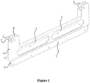
Figure 1 is a schematic view showing the structure of a case bracket according to a first embodiment of the present application; -
Figure 2 is a schematic view showing the structure of the case bracket shown inFigure 1 when the case bracket supports the case; -
Figure 3 is a schematic view showing the structure of the case bracket shown inFigure 2 in a supporting state; -
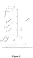
Figure 4 is a structural position view of the case shown inFigure 2 and a wall hanging plate; -
Figure 5 is a structural position view of the case when the case as shown inFigure 2 is vertically mounted; -
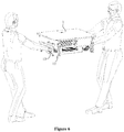
Figure 6 is a structural position view of the case when the case as shown inFigure 2 is horizontally carried; -
Figure 7 is a three-dimensional structure view of the case shown inFigure 2 ; -
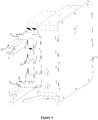
Figure 8 is a three-dimensional structural view of a case bracket according to a second embodiment of the present application; -
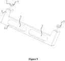
Figure 9 is a three-dimensional structural view of a case bracket according to a third embodiment of the present application; and -
Figure 10 is a structural position view of the case shown inFigure 8 and the wall hanging plate. - A case bracket is provided by the present application for improving the mounting efficiency of the case bracket. A case having the case bracket is further provided by the present application.
- In order to make those skilled in the art to better understand the solution of the present application, the present application will be further described in detail below in conjunction with the drawings and specific embodiments.
- Please refer to
Figures 1 to 10 . - In a specific embodiment, a case bracket according to the specific embodiment of the present application includes a
main body frame 2, a handle portion provided on themain body frame 2, and ahanging device 5 provided on themain body frame 2. - The
hanging device 5 may be a conventional hook. The hangingdevice 5 may be a hanging protrusion or ahanging recess 7 that allows the case body to be hung up. The case body is connected to thewall hanging plate 10 through thehanging recess 7 to achieve the hanging of the case. Specifically, thewall hanging plate 10 is provided with alimiting hole 11 for limiting thehanging device 5. The structure of thehanging device 5 may be adaptively designed according to the structure of thewall hanging plate 10, which is not limited to two embodiments. The wall hanging function may be achieved by asingle case bracket 13, or twocase brackets 13 on opposite sides of thecase body 1 together with other parts. - Specifically, the handle portion may be one or more hanging ring mounted on the
main body frame 2, which depends on actual requirements. The handle portion may be handled by human hands for carrying and mounting the case. - Further, the
main body frame 2 includes amounting portion 6 for fixedly connecting with thecase body 1. Specifically, themounting portion 6 may be detachably connected to thecase body 1. In an actual application, when thecase bracket 13 may be integrally formed with the casing of thecase body 1, themounting portion 6 is a part of the casing of thecase body 1, that is, themounting portion 6 is not required to be individually provided. - The handle portion is a handle protrusion protruding outward from the
mounting portion 6, and the handle protrusion and themounting portion 6 are formed as an integral structure. Specifically, during processing, the integral structure of the handle protrusion and themounting portion 6 may be formed by extrusion. - In order to improve the processing efficiency of the
case bracket 13, preferably, the handle portion is anoperation hole 3 provided in themounting portion 6, and specifically, the number of theoperation hole 3 may be one, two or more. Considering that an operator usually uses both hands when carrying the case, as shown inFigure 6 , preferably, the number of theoperation holes 3 are two. In order to facilitate arranging the operation holes 3 and reducing the overall area, the operation holes 3 are preferably provided along a length direction of the mountingportion 6. - As shown in
Figures 1 to 3 , in order to avoid the situations of the local stress concentration of theoperation hole 3 and scratching the operator, theoperation hole 3 is preferably an oblong hole. - Specifically, when the
case bracket 13 is mounted, thecase body 1 is vertically placed and supported by thecase body bracket 12 of thecase body 1, and then thecase bracket 13 is mounted on thecase body 1 through a locking member. Specifically, the locking member is preferably a threaded fastener. - From the above description, it can be known that, in the case bracket according to the specific embodiment of the present application, the hanging
device 5 and the handle portion are both provided on themain body frame 2 to achieve an integrated setting, and themain body frame 2 is directly mounted with the case body, that is, achieving the mounting of the handle portion and the hangingdevice 5 with the case, thereby the mounting efficiency of thecase bracket 13 is effectively improved. - Further, the
main body frame 2 further includes twosupport legs 9 fixedly connected to the mountingportion 6. The twosupport legs 9 are arranged along the length direction of the mountingportion 6. Twohanging devices 5 are provided and are respectively mounted on the twosupport leg 9. With the setting of thesupport legs 9, it is convenient for the hangingdevice 5 to better achieve the hanging, the overall structural layout is more reasonable, and interference between operations is avoided. - In order to improve the processing efficiency of the
case bracket 13 and reduce the labor intensity of the staff in assembling thecase bracket 13, the hangingdevice 5 and thesupport leg 9 are preferably formed as an integral structure. - Preferably, an end of the hanging
device 5 facing away from the mountingportion 6 is a support surface, and the support surface protrudes outwards from a side of the case body. When the case body is laid flat, as shown inFigure 7 , thecase body 1 may be supported by the end of the hangingdevice 5. Specifically, in order to prolong the service life of thecase bracket 13, asupport plate 8 is preferably provided on the support surface. - In another embodiment, as shown in
Figures 8 to 10 , for example, the second case body bracket shown inFigure 8 and the third case body bracket shown inFigure 9 , the hangingdevice 5 is detachably connected to thesupport leg 9. Specifically, in order to facilitate disassembly of the hangingdevice 5, the hangingdevice 5 and thesupport leg 9 are separated into two parts. Preferably, the hangingdevice 5 is connected to thesupport leg 9 by threads. - In order to improve the use stability of the
case bracket 13 and prolong the service life of thecase bracket 13, preferably, themain body frame 2 further includes a reinforcingrib plate 4 having two ends connected to thesupport legs 9 and the mountingportion 6, respectively. The shape and number of the reinforcingrib plates 4 are determined according to the actual requirements, which are not specifically limited in this application. - Preferably, the
main body frame 2 is formed as an integral structure. More preferably, thecase bracket 13 is formed as an integral structure, thereby reducing the number of the parts of thecase bracket 13, and the handle portion is simply theoperation hole 3, which avoids the situation of individually providing a handle structure, reduces costs, and reduces assembly difficulty. - The
case bracket 13 according to the present application integrates multiple functions such as carrying, wall hanging and supporting, which is easy to operate, convenient to widespread use, simplifies the number of the parts and reduces costs. - Electrical equipment according to the present application includes a
case body 1 and acase bracket 13 which is fixedly connected to thecase body 1 and used to achieve the hanging of thecase body 1, and thecase bracket 13 is any one of theabove case brackets 13. The specific structure and technical effects of thecase bracket 13 have been described above. The case body according to the present application includes theabove case bracket 13 and also has the above technical effects. - Specifically, the electrical equipment may be an inverter or a combiner box. Of course, in specific applications, the
case bracket 13 may also be used for hanging other electrical devices. - In order to ensure the stability of the hanging of the case, preferably, two
case brackets 13 are provided, and the twocase brackets 13 are symmetrically arranged on opposite sides of thecase body 1. More preferably, as shown inFigure 10 , after hanging, the length direction of the mountingportion 6 is arranged perpendicular to the horizontal direction. - The above embodiments are described in a progressive manner. Each of the embodiments is mainly focused on describing its differences from other embodiments, and references may be made among these embodiments with respect to the same or similar sections among these embodiments.
- Based on the above description of the disclosed embodiments, the person skilled in the art can carry out or use the present application. It is obvious for the person skilled in the art to make many modifications to these embodiments. The general principle defined herein may be applied to other embodiments without departing from the spirit or scope of the present application. Therefore, the present application is not limited to the embodiments illustrated herein, but should be defined by the broadest scope consistent with the principle and novel features disclosed herein.
| 1 | case body, | 2 | main body frame, |
| 3 | operation hole, | 4 | reinforcing rib plate, |
| 5 | hanging device, | 6 | mounting portion, |
| 7 | hanging recess, | 8 | supporting plate, |
| 9 | support leg, | 10 | wall hanging plate, |
| 11 | limiting hole, | 12 | case body bracket, |
| 13 | case bracket. |
Claims (15)
- A case bracket, comprising a main body frame (2), a handle portion provided on the main body frame (2), and a hanging device (5) provided on the main body frame (2).
- The case bracket according to claim 1, wherein the main body frame (2) comprises a mounting portion (6) for fixedly connecting to a case body (1).
- The case bracket according to claim 2, wherein the handle portion is a handle protrusion protruding outward from the mounting portion (6), and the handle protrusion and the mounting portion (6) are formed as an integral structure.
- The case bracket according to claim 2, wherein the handle portion is an operation hole (3) provided in the mounting portion (6).
- The case bracket according to claim 4, wherein the operation hole (3) is provided along a length direction of the mounting portion (6).
- The case bracket according to claim 4, wherein the operation hole (3) is an oblong hole.
- The case bracket according to claim 2, wherein the main body frame (2) further comprises two support legs (9) fixedly connected to the mounting portion (6), the two support legs (9) are arranged along the length direction of the mounting portion (6), two hanging devices (5) are provided, the two hanging device (5) are respectively mounted on the two support legs (9).
- The case bracket according to claim 7, wherein the hanging device (5) is a hanging protrusion or a hanging recess (7) configured to allow the case body to be hung up.
- The case bracket according to claim 7, wherein the hanging device (5) and the support leg (9) are formed as an integral structure.
- The case bracket according to claim 9, wherein an end of the hanging device (5) facing away from the mounting portion (6) is a support surface, and the support surface protrudes outward from a side of the case.
- The case bracket according to claim 7, wherein the hanging device (5) is detachably connected to the support leg (9).
- The case bracket according to any one of claims 7 to 11, wherein the main body frame (2) further comprises a reinforcing rib plate (4) having two ends connected to the support leg (9) and the mounting portion (6), respectively.
- An electrical equipment, comprising a case body (1), wherein the electric equipment further comprises a case bracket (13) fixedly connected to the case body (1) and configured to allow the case body (1) to be hung up, and the case bracket (13) is the case bracket (13) according to any one of claims 1 to 12.
- The electrical equipment according to claim 13, wherein the electrical equipment is an inverter or a combiner box.
- The electrical equipment according to claim 13, wherein two case brackets (13) are provided, and the two case brackets (13) are symmetrically arranged on opposite sides of the case body (1).
Applications Claiming Priority (1)
| Application Number | Priority Date | Filing Date | Title |
|---|---|---|---|
| CN201910214112.XA CN109862731B (en) | 2019-03-20 | 2019-03-20 | Chassis brackets and electrical equipment |
Publications (1)
| Publication Number | Publication Date |
|---|---|
| EP3711631A1 true EP3711631A1 (en) | 2020-09-23 |
Family
ID=66901371
Family Applications (1)
| Application Number | Title | Priority Date | Filing Date |
|---|---|---|---|
| EP20155034.0A Pending EP3711631A1 (en) | 2019-03-20 | 2020-01-31 | Case bracket and electric equipment |
Country Status (4)
| Country | Link |
|---|---|
| EP (1) | EP3711631A1 (en) |
| KR (2) | KR102533053B1 (en) |
| CN (1) | CN109862731B (en) |
| AU (2) | AU2020200403B2 (en) |
Citations (2)
| Publication number | Priority date | Publication date | Assignee | Title |
|---|---|---|---|---|
| US4285484A (en) * | 1979-06-07 | 1981-08-25 | Follows James S | Shelf and clothes rod assembly for a closet |
| US20180110346A1 (en) * | 2016-10-24 | 2018-04-26 | Lowes Companies, Inc. | Wall-Mountable Bracket for Various Shelf Configurations |
Family Cites Families (15)
| Publication number | Priority date | Publication date | Assignee | Title |
|---|---|---|---|---|
| US3471112A (en) * | 1967-11-21 | 1969-10-07 | Px Ind Inc | Combination shelf support and anchor |
| DE4232841C2 (en) * | 1992-09-30 | 1995-02-09 | Siemens Ag | Arrangement for attaching a cuboid device |
| CN2532516Y (en) * | 2002-03-22 | 2003-01-22 | 力捷电脑股份有限公司 | Dual-use structure of handle and hanger |
| US6811039B2 (en) * | 2002-12-06 | 2004-11-02 | King Slide Works Co., Ltd. | Detachable device of a cable management arm for furniture |
| JP5289866B2 (en) * | 2008-08-29 | 2013-09-11 | 三菱電線工業株式会社 | Optical termination box |
| CN202302635U (en) * | 2011-10-20 | 2012-07-04 | 深圳古瑞瓦特新能源有限公司 | Wall-hanging structure and inverter comprising same |
| CN202404484U (en) * | 2011-12-09 | 2012-08-29 | 公信电子股份有限公司 | Simple computer hanging rack structure |
| CN202634911U (en) * | 2012-04-25 | 2012-12-26 | 深圳市英威腾电气股份有限公司 | Case |
| CN204350486U (en) * | 2014-12-17 | 2015-05-20 | 精英电脑股份有限公司 | combination device |
| CN205051594U (en) * | 2015-11-02 | 2016-02-24 | 阳光电源股份有限公司 | Hanging structure and wall -hanging power inverter who has said hanging structure |
| CN205910642U (en) * | 2016-06-15 | 2017-01-25 | 联想(北京)有限公司 | Hard disc support and quick -witted case |
| CN205812567U (en) * | 2016-06-30 | 2016-12-14 | 广州视睿电子科技有限公司 | Multifunctional handle device for intelligent tablet computer |
| CN205960987U (en) * | 2016-08-22 | 2017-02-15 | 深圳市一元科技股份有限公司 | Hanging dc -to -ac converter |
| CN208074534U (en) * | 2018-04-19 | 2018-11-09 | 北京汉能光伏投资有限公司 | Hanging structure |
| CN208401798U (en) * | 2018-07-23 | 2019-01-18 | 安徽国际商务职业学院 | A kind of novel wall-mounted photovoltaic DC-to-AC converter |
-
2019
- 2019-03-20 CN CN201910214112.XA patent/CN109862731B/en active Active
-
2020
- 2020-01-21 AU AU2020200403A patent/AU2020200403B2/en active Active
- 2020-01-21 KR KR1020200007685A patent/KR102533053B1/en active Active
- 2020-01-31 EP EP20155034.0A patent/EP3711631A1/en active Pending
-
2021
- 2021-11-03 AU AU2021261874A patent/AU2021261874B2/en active Active
-
2022
- 2022-01-03 KR KR1020220000080A patent/KR20220009467A/en not_active Ceased
Patent Citations (2)
| Publication number | Priority date | Publication date | Assignee | Title |
|---|---|---|---|---|
| US4285484A (en) * | 1979-06-07 | 1981-08-25 | Follows James S | Shelf and clothes rod assembly for a closet |
| US20180110346A1 (en) * | 2016-10-24 | 2018-04-26 | Lowes Companies, Inc. | Wall-Mountable Bracket for Various Shelf Configurations |
Also Published As
| Publication number | Publication date |
|---|---|
| KR20220009467A (en) | 2022-01-24 |
| AU2020200403A1 (en) | 2020-10-08 |
| KR102533053B1 (en) | 2023-05-16 |
| AU2021261874B2 (en) | 2023-08-31 |
| CN109862731A (en) | 2019-06-07 |
| KR20200113158A (en) | 2020-10-06 |
| CN109862731B (en) | 2021-11-02 |
| AU2021261874A1 (en) | 2021-12-02 |
| AU2020200403B2 (en) | 2021-08-05 |
Similar Documents
| Publication | Publication Date | Title |
|---|---|---|
| KR102623220B1 (en) | Framework of laundry processing device, and laundry processing device | |
| WO2018095144A1 (en) | Bracket connection structure and bracket | |
| CN109843159A (en) | Medical Devices | |
| AU2020200403B2 (en) | Case bracket and electric equipment | |
| CN210432281U (en) | An intelligent touch panel with its own snap connection structure | |
| CN206211073U (en) | A kind of open-ended energization and load-bearing link and connector | |
| CN209950819U (en) | A sofa and its components | |
| CN209994503U (en) | A storage rack for IoT gateway installation | |
| CN210643462U (en) | Show shelf structure with adjustable plywood | |
| CN210609991U (en) | Display screen box body structure and LED display screen with same | |
| CN217603807U (en) | Wall hanging device | |
| CN222503318U (en) | Wall-mounted structure and wall-mounted integrated machine | |
| CN216163025U (en) | Packaging structure of switching power supply | |
| CN219414325U (en) | Inverter wall hanging device and electrical equipment | |
| CN218219504U (en) | Light and handy negotiation table | |
| CN210518124U (en) | Inverter cabinet structure | |
| CN112952561B (en) | Power distribution cabinet frame structure and matching method | |
| CN110307496A (en) | Borderless Panel Light | |
| CN212786476U (en) | High-power circuit board | |
| CN218791159U (en) | electric heating table | |
| CN219249468U (en) | Lifting table with screen | |
| CN218732969U (en) | Fixed bolster for control line | |
| KR101569082B1 (en) | Solar power roof apparatus | |
| CN219889090U (en) | Wall-hanging structure of inverter | |
| CN223334281U (en) | An electrical cabinet |
Legal Events
| Date | Code | Title | Description |
|---|---|---|---|
| PUAI | Public reference made under article 153(3) epc to a published international application that has entered the european phase |
Free format text: ORIGINAL CODE: 0009012 |
|
| STAA | Information on the status of an ep patent application or granted ep patent |
Free format text: STATUS: THE APPLICATION HAS BEEN PUBLISHED |
|
| AK | Designated contracting states |
Kind code of ref document: A1 Designated state(s): AL AT BE BG CH CY CZ DE DK EE ES FI FR GB GR HR HU IE IS IT LI LT LU LV MC MK MT NL NO PL PT RO RS SE SI SK SM TR |
|
| AX | Request for extension of the european patent |
Extension state: BA ME |
|
| RAP1 | Party data changed (applicant data changed or rights of an application transferred) |
Owner name: SUNGROW POWER SUPPLY CO., LTD. |
|
| RIN1 | Information on inventor provided before grant (corrected) |
Inventor name: HUANG, ZHIFENG Inventor name: SHEN, ZHANLIANG |
|
| STAA | Information on the status of an ep patent application or granted ep patent |
Free format text: STATUS: REQUEST FOR EXAMINATION WAS MADE |
|
| 17P | Request for examination filed |
Effective date: 20201013 |
|
| RBV | Designated contracting states (corrected) |
Designated state(s): AL AT BE BG CH CY CZ DE DK EE ES FI FR GB GR HR HU IE IS IT LI LT LU LV MC MK MT NL NO PL PT RO RS SE SI SK SM TR |
|
| STAA | Information on the status of an ep patent application or granted ep patent |
Free format text: STATUS: EXAMINATION IS IN PROGRESS |
|
| 17Q | First examination report despatched |
Effective date: 20201218 |
|
| GRAP | Despatch of communication of intention to grant a patent |
Free format text: ORIGINAL CODE: EPIDOSNIGR1 |
|
| STAA | Information on the status of an ep patent application or granted ep patent |
Free format text: STATUS: GRANT OF PATENT IS INTENDED |
|
| INTG | Intention to grant announced |
Effective date: 20260414 |