EP3711604A1 - Aerosol delivery system - Google Patents
Aerosol delivery system Download PDFInfo
- Publication number
- EP3711604A1 EP3711604A1 EP19164457.4A EP19164457A EP3711604A1 EP 3711604 A1 EP3711604 A1 EP 3711604A1 EP 19164457 A EP19164457 A EP 19164457A EP 3711604 A1 EP3711604 A1 EP 3711604A1
- Authority
- EP
- European Patent Office
- Prior art keywords
- aerosol
- fluid
- heater
- transfer article
- carrier
- Prior art date
- Legal status (The legal status is an assumption and is not a legal conclusion. Google has not performed a legal analysis and makes no representation as to the accuracy of the status listed.)
- Ceased
Links
- 239000000443 aerosol Substances 0.000 title claims abstract description 175
- 238000012546 transfer Methods 0.000 claims abstract description 80
- 230000004913 activation Effects 0.000 claims abstract description 52
- 239000002243 precursor Substances 0.000 claims abstract description 46
- 230000037361 pathway Effects 0.000 claims abstract description 18
- 239000000463 material Substances 0.000 claims description 26
- 239000011521 glass Substances 0.000 claims description 9
- 239000002861 polymer material Substances 0.000 claims description 7
- OKTJSMMVPCPJKN-UHFFFAOYSA-N Carbon Chemical compound [C] OKTJSMMVPCPJKN-UHFFFAOYSA-N 0.000 claims description 6
- 229910052799 carbon Inorganic materials 0.000 claims description 6
- 239000000919 ceramic Substances 0.000 claims description 6
- 238000004891 communication Methods 0.000 claims description 5
- 239000002657 fibrous material Substances 0.000 claims description 4
- 239000011888 foil Substances 0.000 claims description 4
- 239000000835 fiber Substances 0.000 claims description 3
- 239000006260 foam Substances 0.000 claims description 3
- 239000012530 fluid Substances 0.000 abstract description 19
- SNICXCGAKADSCV-JTQLQIEISA-N (-)-Nicotine Chemical compound CN1CCC[C@H]1C1=CC=CN=C1 SNICXCGAKADSCV-JTQLQIEISA-N 0.000 description 20
- 229960002715 nicotine Drugs 0.000 description 20
- SNICXCGAKADSCV-UHFFFAOYSA-N nicotine Natural products CN1CCCC1C1=CC=CN=C1 SNICXCGAKADSCV-UHFFFAOYSA-N 0.000 description 20
- 239000011148 porous material Substances 0.000 description 14
- 239000007788 liquid Substances 0.000 description 13
- 230000008867 communication pathway Effects 0.000 description 12
- 241000208125 Nicotiana Species 0.000 description 8
- 235000002637 Nicotiana tabacum Nutrition 0.000 description 8
- 238000010438 heat treatment Methods 0.000 description 8
- -1 nicotine compound Chemical class 0.000 description 7
- 239000000758 substrate Substances 0.000 description 7
- 238000000034 method Methods 0.000 description 6
- 239000000203 mixture Substances 0.000 description 6
- 230000008569 process Effects 0.000 description 5
- 230000000391 smoking effect Effects 0.000 description 5
- 239000004696 Poly ether ether ketone Substances 0.000 description 4
- 239000004697 Polyetherimide Substances 0.000 description 4
- 239000004642 Polyimide Substances 0.000 description 4
- 239000004743 Polypropylene Substances 0.000 description 4
- 230000004888 barrier function Effects 0.000 description 4
- 230000000694 effects Effects 0.000 description 4
- 239000003595 mist Substances 0.000 description 4
- 229920002530 polyetherether ketone Polymers 0.000 description 4
- 229920001601 polyetherimide Polymers 0.000 description 4
- 229920000139 polyethylene terephthalate Polymers 0.000 description 4
- 239000005020 polyethylene terephthalate Substances 0.000 description 4
- 229920001721 polyimide Polymers 0.000 description 4
- 229920001155 polypropylene Polymers 0.000 description 4
- 229920001343 polytetrafluoroethylene Polymers 0.000 description 4
- 239000004810 polytetrafluoroethylene Substances 0.000 description 4
- 239000000126 substance Substances 0.000 description 4
- 238000009834 vaporization Methods 0.000 description 4
- DNIAPMSPPWPWGF-UHFFFAOYSA-N Propylene glycol Chemical compound CC(O)CO DNIAPMSPPWPWGF-UHFFFAOYSA-N 0.000 description 3
- 150000001875 compounds Chemical class 0.000 description 3
- PEDCQBHIVMGVHV-UHFFFAOYSA-N Glycerine Chemical compound OCC(O)CO PEDCQBHIVMGVHV-UHFFFAOYSA-N 0.000 description 2
- 239000004699 Ultra-high molecular weight polyethylene Substances 0.000 description 2
- 238000012387 aerosolization Methods 0.000 description 2
- 238000000889 atomisation Methods 0.000 description 2
- 230000015556 catabolic process Effects 0.000 description 2
- 230000008859 change Effects 0.000 description 2
- 235000019504 cigarettes Nutrition 0.000 description 2
- 230000008878 coupling Effects 0.000 description 2
- 238000010168 coupling process Methods 0.000 description 2
- 238000005859 coupling reaction Methods 0.000 description 2
- 238000006731 degradation reaction Methods 0.000 description 2
- 239000003571 electronic cigarette Substances 0.000 description 2
- 238000001914 filtration Methods 0.000 description 2
- 239000000796 flavoring agent Substances 0.000 description 2
- 230000006870 function Effects 0.000 description 2
- 238000003780 insertion Methods 0.000 description 2
- 230000037431 insertion Effects 0.000 description 2
- 210000004072 lung Anatomy 0.000 description 2
- 238000002670 nicotine replacement therapy Methods 0.000 description 2
- 235000019505 tobacco product Nutrition 0.000 description 2
- 229920000785 ultra high molecular weight polyethylene Polymers 0.000 description 2
- 238000011144 upstream manufacturing Methods 0.000 description 2
- 230000008016 vaporization Effects 0.000 description 2
- HBBGRARXTFLTSG-UHFFFAOYSA-N Lithium ion Chemical compound [Li+] HBBGRARXTFLTSG-UHFFFAOYSA-N 0.000 description 1
- 206010057852 Nicotine dependence Diseases 0.000 description 1
- 230000009471 action Effects 0.000 description 1
- 239000013543 active substance Substances 0.000 description 1
- 238000013019 agitation Methods 0.000 description 1
- 230000006399 behavior Effects 0.000 description 1
- 230000008901 benefit Effects 0.000 description 1
- 238000009835 boiling Methods 0.000 description 1
- 239000002775 capsule Substances 0.000 description 1
- 235000019506 cigar Nutrition 0.000 description 1
- 238000002485 combustion reaction Methods 0.000 description 1
- 238000010276 construction Methods 0.000 description 1
- 230000007423 decrease Effects 0.000 description 1
- 230000003247 decreasing effect Effects 0.000 description 1
- 238000001514 detection method Methods 0.000 description 1
- 238000009792 diffusion process Methods 0.000 description 1
- 239000003814 drug Substances 0.000 description 1
- 238000001704 evaporation Methods 0.000 description 1
- 230000008020 evaporation Effects 0.000 description 1
- 230000007717 exclusion Effects 0.000 description 1
- 239000010419 fine particle Substances 0.000 description 1
- 235000011187 glycerol Nutrition 0.000 description 1
- 230000000977 initiatory effect Effects 0.000 description 1
- 239000007791 liquid phase Substances 0.000 description 1
- 229910001416 lithium ion Inorganic materials 0.000 description 1
- 230000007774 longterm Effects 0.000 description 1
- 230000004048 modification Effects 0.000 description 1
- 238000012986 modification Methods 0.000 description 1
- 210000004877 mucosa Anatomy 0.000 description 1
- 210000004400 mucous membrane Anatomy 0.000 description 1
- 229940087730 nicorette Drugs 0.000 description 1
- 239000002245 particle Substances 0.000 description 1
- 239000012071 phase Substances 0.000 description 1
- 229920003023 plastic Polymers 0.000 description 1
- 239000004033 plastic Substances 0.000 description 1
- 230000002685 pulmonary effect Effects 0.000 description 1
- 230000000717 retained effect Effects 0.000 description 1
- 238000007789 sealing Methods 0.000 description 1
- 230000035807 sensation Effects 0.000 description 1
- 239000000779 smoke Substances 0.000 description 1
- 230000001225 therapeutic effect Effects 0.000 description 1
- 231100000167 toxic agent Toxicity 0.000 description 1
- 239000003440 toxic substance Substances 0.000 description 1
- 230000007704 transition Effects 0.000 description 1
- 239000006200 vaporizer Substances 0.000 description 1
- 239000011800 void material Substances 0.000 description 1
Images




Classifications
-
- A—HUMAN NECESSITIES
- A24—TOBACCO; CIGARS; CIGARETTES; SIMULATED SMOKING DEVICES; SMOKERS' REQUISITES
- A24F—SMOKERS' REQUISITES; MATCH BOXES; SIMULATED SMOKING DEVICES
- A24F40/00—Electrically operated smoking devices; Component parts thereof; Manufacture thereof; Maintenance or testing thereof; Charging means specially adapted therefor
- A24F40/40—Constructional details, e.g. connection of cartridges and battery parts
- A24F40/44—Wicks
-
- A—HUMAN NECESSITIES
- A61—MEDICAL OR VETERINARY SCIENCE; HYGIENE
- A61M—DEVICES FOR INTRODUCING MEDIA INTO, OR ONTO, THE BODY; DEVICES FOR TRANSDUCING BODY MEDIA OR FOR TAKING MEDIA FROM THE BODY; DEVICES FOR PRODUCING OR ENDING SLEEP OR STUPOR
- A61M11/00—Sprayers or atomisers specially adapted for therapeutic purposes
- A61M11/001—Particle size control
- A61M11/003—Particle size control by passing the aerosol trough sieves or filters
-
- A—HUMAN NECESSITIES
- A61—MEDICAL OR VETERINARY SCIENCE; HYGIENE
- A61M—DEVICES FOR INTRODUCING MEDIA INTO, OR ONTO, THE BODY; DEVICES FOR TRANSDUCING BODY MEDIA OR FOR TAKING MEDIA FROM THE BODY; DEVICES FOR PRODUCING OR ENDING SLEEP OR STUPOR
- A61M11/00—Sprayers or atomisers specially adapted for therapeutic purposes
- A61M11/04—Sprayers or atomisers specially adapted for therapeutic purposes operated by the vapour pressure of the liquid to be sprayed or atomised
- A61M11/041—Sprayers or atomisers specially adapted for therapeutic purposes operated by the vapour pressure of the liquid to be sprayed or atomised using heaters
- A61M11/042—Sprayers or atomisers specially adapted for therapeutic purposes operated by the vapour pressure of the liquid to be sprayed or atomised using heaters electrical
-
- A—HUMAN NECESSITIES
- A61—MEDICAL OR VETERINARY SCIENCE; HYGIENE
- A61M—DEVICES FOR INTRODUCING MEDIA INTO, OR ONTO, THE BODY; DEVICES FOR TRANSDUCING BODY MEDIA OR FOR TAKING MEDIA FROM THE BODY; DEVICES FOR PRODUCING OR ENDING SLEEP OR STUPOR
- A61M15/00—Inhalators
- A61M15/06—Inhaling appliances shaped like cigars, cigarettes or pipes
-
- A—HUMAN NECESSITIES
- A24—TOBACCO; CIGARS; CIGARETTES; SIMULATED SMOKING DEVICES; SMOKERS' REQUISITES
- A24F—SMOKERS' REQUISITES; MATCH BOXES; SIMULATED SMOKING DEVICES
- A24F40/00—Electrically operated smoking devices; Component parts thereof; Manufacture thereof; Maintenance or testing thereof; Charging means specially adapted therefor
- A24F40/10—Devices using liquid inhalable precursors
-
- A—HUMAN NECESSITIES
- A61—MEDICAL OR VETERINARY SCIENCE; HYGIENE
- A61M—DEVICES FOR INTRODUCING MEDIA INTO, OR ONTO, THE BODY; DEVICES FOR TRANSDUCING BODY MEDIA OR FOR TAKING MEDIA FROM THE BODY; DEVICES FOR PRODUCING OR ENDING SLEEP OR STUPOR
- A61M16/00—Devices for influencing the respiratory system of patients by gas treatment, e.g. ventilators; Tracheal tubes
- A61M16/0003—Accessories therefor, e.g. sensors, vibrators, negative pressure
- A61M2016/0015—Accessories therefor, e.g. sensors, vibrators, negative pressure inhalation detectors
- A61M2016/0018—Accessories therefor, e.g. sensors, vibrators, negative pressure inhalation detectors electrical
-
- A—HUMAN NECESSITIES
- A61—MEDICAL OR VETERINARY SCIENCE; HYGIENE
- A61M—DEVICES FOR INTRODUCING MEDIA INTO, OR ONTO, THE BODY; DEVICES FOR TRANSDUCING BODY MEDIA OR FOR TAKING MEDIA FROM THE BODY; DEVICES FOR PRODUCING OR ENDING SLEEP OR STUPOR
- A61M2205/00—General characteristics of the apparatus
- A61M2205/33—Controlling, regulating or measuring
- A61M2205/3368—Temperature
-
- A—HUMAN NECESSITIES
- A61—MEDICAL OR VETERINARY SCIENCE; HYGIENE
- A61M—DEVICES FOR INTRODUCING MEDIA INTO, OR ONTO, THE BODY; DEVICES FOR TRANSDUCING BODY MEDIA OR FOR TAKING MEDIA FROM THE BODY; DEVICES FOR PRODUCING OR ENDING SLEEP OR STUPOR
- A61M2205/00—General characteristics of the apparatus
- A61M2205/75—General characteristics of the apparatus with filters
Definitions
- the present invention relates to an aerosol delivery system, and an aerosol-generation apparatus for an aerosol delivery system.
- the present invention preferably relates to an aerosol delivery system including a heater configured to heat an aerosol precursor to generate an aerosolised composition for inhalation by a user, and to an aerosol-generation apparatus therefor.
- Pharmaceutical medicament physiologically active substances and flavourings for example may be delivered to the human body by inhalation through the mouth and/or nose.
- Such material or substances may be delivered directly to the mucosa or mucous membrane lining the nasal and oral passages and/or the pulmonary system.
- nicotine is consumed for therapeutic or recreational purposes and may be delivered to the body in a number of ways. Nicotine replacement therapies are aimed at people who wish to stop smoking and overcome their dependence on nicotine. Nicotine is delivered to the body in the form of aerosol delivery devices and systems, also known as smoking-substitute devices or nicotine delivery devices. Such devices may be non-powered or powered.
- Devices or systems that are non-powered may comprise nicotine replacement therapy devices such as "inhalators”, e.g. Nicorette® Inhalator. These generally have the appearance of a plastic cigarette and are used by people who crave the behaviour associated with consumption of combustible tobacco - the so-called hand-to-mouth aspect - of smoking tobacco.
- Inhalators generally allow nicotine-containing aerosol to be inhaled through an elongate tube in which a container containing a nicotine carrier, for example, a substrate, is located. An air stream caused by suction through the tube by the user carries nicotine vapours into the lungs of the user to satisfy a nicotine craving.
- the container may comprise a replaceable cartridge, which includes a cartridge housing and a passageway in the housing in which a nicotine reservoir is located.
- the reservoir holds a measured amount of nicotine in the form of the nicotine carrier.
- the measured amount of nicotine is an amount suitable for delivering a specific number of "doses".
- the form of the nicotine carrier is such as to allow nicotine vapour to be released into a fluid stream passing around or through the reservoir. This process is known as aerosolization and or atomization. Aerosolization is the process or act of converting a physical substance into the form of particles small and light enough to be carried on the air i.e. into an aerosol.
- Atomization is the process or act of separating or reducing a physical substance into fine particles and may include the generation of aerosols.
- the passageway generally has an opening at each end for communication with the exterior of the housing and for allowing the fluid stream through the passageway.
- a nicotine-impermeable barrier seals the reservoir from atmosphere.
- the barrier includes passageway barrier portions for sealing the passageway on both sides of the reservoir. These barrier portions are frangible so as to be penetrable for opening the passageway to atmosphere.
- a device or a system that is powered can fall into two sub-categories.
- such devices or systems may comprise electronic devices or systems that permit a user to simulate the act of smoking by producing an aerosol mist or vapour that is drawn into the lungs through the mouth and then exhaled.
- the electronic devices or systems typically cause the vaporization of a liquid containing nicotine and entrainment of the vapour into an airstream. Vaporization of an element or compound is a phase transition from the liquid phase to vapour i.e. evaporation or boiling.
- the user experiences a similar satisfaction and physical sensation to those experienced from a traditional smoking or tobacco product, and exhales an aerosol mist or vapour of similar appearance to the smoke exhaled when using such traditional smoking or tobacco products.
- devices or systems of the second, powered category include, but are not limited to, electronic nicotine delivery systems, electronic cigarettes, e-cigarettes, e-cigs, vaping cigarettes, pipes, cigars, cigarillos, vaporizers and devices of a similar nature that function to produce an aerosol mist or vapour that is inhaled by a user.
- Such nicotine delivery devices or systems of the second category incorporate a liquid reservoir element generally including a vaporizer or misting element such as a heating element or other suitable element, and are known, inter alia, as atomizers, cartomizers, or clearomizers.
- Some electronic cigarettes are disposable; others are reusable, with replaceable and refillable parts.
- Aerosol delivery devices or systems in a first sub-category of the second, powered category generally use heat and/or ultrasonic agitation to vaporize a solution comprising nicotine and/or other flavouring, propylene glycol and/or glycerine-based base into an aerosol mist of vapour for inhalation.
- Aerosol delivery devices or systems in a second sub-category of the second, powered category may typically comprise devices or systems in which tobacco is heated rather than combusted.
- volatile compounds may be released from the tobacco by heat transfer from the heat source and entrained in air drawn through the aerosol delivery device or system.
- Direct contact between a heat source of the aerosol delivery device or system and the tobacco heats the tobacco to form an aerosol.
- the aerosol containing the released compounds passes through the device, it cools and condenses to form an aerosol for inhalation by the user.
- heating, as opposed to burning the tobacco may reduce the odour that can arise through combustion and pyrolytic degradation of tobacco.
- Aerosol delivery devices or systems falling into the first sub-category of powered devices or systems may typically comprise a powered unit, comprising a heater element, which is arranged to heat a portion of a carrier that holds an aerosol precursor.
- the carrier comprises a substrate formed of a "wicking" material, which can absorb aerosol precursor liquid from a reservoir and hold the aerosol precursor liquid.
- aerosol precursor liquid in the portion of the carrier in the vicinity of the heater element is vaporised and released from the carrier into an airstream flowing around the heater and carrier. Released aerosol precursor is entrained into the airstream to be borne by the airstream to an outlet of the device or system, from where it can be inhaled by a user.
- the heater element is typically a resistive coil heater, which is wrapped around a portion of the carrier and is usually located in the liquid reservoir of the device or system. Consequently, the surface of the heater may always be in contact with the aerosol precursor liquid, and long-term exposure may result in the degradation of either or both of the liquid and heater. Furthermore, residues may build up upon the surface of the heater element, which may result in undesirable toxicants being inhaled by the user. Furthermore, as the level of liquid in the reservoir diminishes through use, regions of the heater element may become exposed and overheat.
- the present invention has been devised in light of the above considerations.
- an aerosol-generation apparatus has a fluid-transfer article which holds aerosol precursor and which transfers that aerosol precursor to an activation surface. That activation surface is in abutting unbonded contact with a heater of the aerosol-generation apparatus, and an air-flow pathway is defined on the opposite side of the heater from the activation surface.
- the fluid-transfer article is separable from the rest of the aerosol-generation apparatus.
- the activation surface is in contact with the heater so that it will be heated when the heater is active. Since that contact is unbonded, the activation surface and heater are separable and will separate from one another when the fluid-transfer article is removed from the rest of the aerosol-generation apparatus. Since the aerosol precursor will be consumed as the user uses the apparatus, this will allow the fluid-transfer article to be removed, and be replaced or refilled with aerosol precursor, without needing to replace the heater.
- an aerosol-generation apparatus comprising a heater and a separable fluid-transfer article, the fluid-transfer article comprising a first region for holding an aerosol precursor and for transferring said aerosol precursor to an activation surface of a second region of said fluid-transfer article, said activation surface being being in abutting unbonded contact with said heater so as to interact thermally with said heater, the apparatus having an air-flow pathway on the opposite side of said heater from said activation surface.
- the activation surface is preferably planar to allow it to make good contact with the heater.
- the heater is preferably a foil or mesh heater.
- the heater will normally need to have at least one gap forming an opening therein to enable heated aerosol precursor, in the form of vapour and/or a vapour/aerosol mixture, to pass through the heater from the activation surface to the air-flow pathway.
- the second region of the fluid-transfer article which forms the activation surface will normally have a wicking effect, so that aerosol precursor in the fluid-transfer article will be transported to the activation surface.
- second region may be formed of a porous polymer material.
- it may be formed of a fibrous material, such as glass or ceramic fibre material.
- Other alternatives include sintered glass, ceramic or carbon, or carbon or glass foam.
- the first part of the fluid-transfer article may act as a reservoir for the aerosol precursor. That region may simply be a tank for liquid, or may be of porous polymer material which holds the aerosol precursor.
- the aerosol-generation apparatus may form part of an aerosol delivery system which has a carrier and which may include a housing containing the fluid-transfer apparatus. There may then be a further housing supporting the heater and in which a part of the air-flow pathway is formed. Thus, the fluid-transfer article may be separable from the rest of the apparatus by removing the carrier therefrom.
- the invention includes the combination of the aspects and preferred features described except where such a combination is clearly impermissible or expressly avoided.
- one or more embodiments in accordance with the present invention may provide a system for aerosol delivery in which an aerosol carrier may be inserted into a receptacle (e.g. a "heating chamber") of an apparatus for initiating and maintaining release of an aerosol from the aerosol carrier.
- a receptacle e.g. a "heating chamber”
- Another end, or another end portion, of the aerosol carrier may protrude from the apparatus and can be inserted into the mouth of a user for the inhalation of aerosol released from the aerosol carrier cartridge during operation of the apparatus.
- system for aerosol delivery shall be referred to as "aerosol delivery system”.
- FIG. 1 there is illustrated a perspective view of an aerosol delivery system 10 comprising an aerosol generation apparatus 12 operative to initiate and maintain release of aerosol from a fluid-transfer article in an aerosol carrier 14.
- the aerosol carrier 14 is shown with a first end 16 thereof and a portion of the length of the aerosol carrier 14 located within a receptacle of the apparatus 12. A remaining portion of the aerosol carrier 14 extends out of the receptacle. This remaining portion of the aerosol carrier 14, terminating at a second end 18 of the aerosol carrier, is configured for insertion into a user's mouth.
- a vapour and/or aerosol is produced when a heater (not shown in Figure 1 ) of the apparatus 12 heats a fluid-transfer article in the aerosol carrier 14 to release a vapour and/or an aerosol, and this can be delivered to the user, when the user sucks or inhales, via a fluid passage in communication with an outlet of the aerosol carrier 14 from the fluid-transfer article to the second end 18.
- the device 12 also comprises air-intake apertures 20 in the housing of the apparatus 12 to provide a passage for air to be drawn into the interior of the apparatus 12 (when the user sucks or inhales) for delivery to the first end 16 of the aerosol carrier 14, so that the air can be drawn across an activation surface of a fluid-transfer article located within a housing of the aerosol carrier cartridge 14 during use.
- these apertures may be perforations in the housing of the apparatus 12.
- a fluid-transfer article (not shown in Figure 1 , but described hereinafter with reference to Figs. 5 to 7 is located within a housing of the aerosol carrier 14.
- the fluid-transfer article contains an aerosol precursor material, which may include at least one of: nicotine; a nicotine precursor material; a nicotine compound; and one or more flavourings.
- the fluid-transfer article is located within the housing of the aerosol carrier 14 to allow air drawn into the aerosol carrier 14 at, or proximal, the first end 16 to flow across an activation surface of the fluid-transfer article.
- an aerosol may be entrained in the air stream from a substrate forming the fluid-transfer article, e.g. via diffusion from the substrate to the air stream and/or via vaporisation of the aerosol precursor material and release from the fluid-transfer article under heating.
- the substrate forming the fluid-transfer article 34 may at least partly comprise a porous material where pores of the porous material hold, contain, carry, or bear the aerosol precursor material.
- the porous material of the fluid-transfer article is a porous polymer material such as, for example, a sintered material.
- material suitable for the fluid-transfer article include: Polyetherimide (PEI); Polytetrafluoroethylene (PTFE); Polyether ether ketone (PEEK); Polyimide (PI); Polyethersulphone (PES); and Ultra-High Molecular Weight Polyethylene.
- Other suitable materials may comprise, for example, BioVyonTM (by Porvair Filtration Group Ltd) and materials available from Porex®.
- a substrate forming the fluid-transfer article may comprise Polypropylene (PP) or Polyethylene Terephthalate (PET). All such materials may be described as heat resistant polymeric wicking material in the context of the present invention.
- the aerosol carrier 14 is removable from the apparatus 12 so that it may be disposed of when expired. After removal of a used aerosol carrier 14, a replacement aerosol carrier 14 can be inserted into the apparatus 12 to replace the used aerosol carrier 14.
- FIG 2 is a cross-sectional side view illustration of a part of apparatus 12 of the aerosol delivery system 10.
- the apparatus 12 comprises a receptacle 22 in which is located a portion of the aerosol carrier 14. In one or more optional arrangements, the receptacle 22 may enclose the aerosol carrier 14.
- the apparatus 12 also comprises a heater 24, which opposes an activation surface of the fluid-transfer article (not shown in Figure 2 ) of the aerosol carrier 14 when an aerosol carrier 14 is located within the receptacle 22.
- an aerosol is released, or liberated, from the fluid-transfer article, and is drawn from the material of the aerosol carrier unit by the air flowing across the activation surface and is transported in the air flow to via outlet conduits (not shown in Figure 2 ) in the housing of the aerosol carrier 14 to the second end 18.
- outlet conduits not shown in Figure 2
- the direction of air flow is illustrated by arrows in Figure 2 .
- the fluid-transfer article of the aerosol carrier 14 is heated by the heater 24.
- the aerosol released from the fluid-transfer article and entrained in the air flowing across the activation surface of the fluid-transfer article is drawn through the outlet conduits (not shown) in the housing of the aerosol carrier 14 towards the second end 18 and onwards into the user's mouth.
- apparatus 12 comprises a housing 26, in which are located the receptacle 22 and heater 24.
- the housing 26 also contains control circuitry (not shown) operative by a user, or upon detection of air and/or vapour being drawn into the device 12 through air-intake apertures 20, i.e. when the user sucks or inhales.
- the housing 26 comprises an electrical energy supply 28, for example a battery.
- the battery comprises a rechargeable lithium ion battery.
- the housing 26 also comprises a coupling 30 for electrically (and optionally mechanically) coupling the electrical energy supply 28 to control circuitry (not shown) for powering and controlling operation of the heater 24.
- the heater 24 heats the fluid-transfer article (not shown in Figure 3 ) of aerosol carrier 14.
- This heating process initiates (and, through continued operation, maintains) release of vapour and/or an aerosol from the activation surface of the fluid-transfer article.
- the vapour and/or aerosol formed as a result of the heating process is entrained into a stream of air (as the user sucks or inhales).
- the stream of air with the entrained vapour and/or aerosol passes through the aerosol carrier 14 via outlet conduits (not shown) and exits the aerosol carrier 14 at second end 18 for delivery to the user.
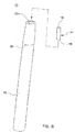
- Figures 4 to 6 schematically illustrate the aerosol carrier 14 in more detail (and, in Figure 5 , features within the receptacle in more detail).
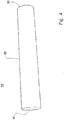
- Figure 4 illustrates an exterior of the aerosol carrier 14, and
- Figure 5 illustrates internal components of the aerosol carrier 14 in one optional configuration.
- Fig. 4 illustrates the exterior of the aerosol carrier 14, which comprises housing 32 for housing said fluid-transfer article (not shown) and at least one other internal component.
- the particular housing 32 illustrated in Figure 4 comprises a tubular member, which may be generally cylindrical in form, and which is configured to be received within the receptacle of the apparatus.
- First end 16 of the aerosol carrier 14 is for location to oppose the heater of the apparatus, and second end 18 (and the region adjacent the second end 18) is configured for insertion into a user's mouth.
- FIG. 5 illustrates some internal components of the aerosol carrier 14 and of the heater 24 of apparatus 12, in in one embodiment of the invention.
- the aerosol carrier 14 comprises a fluid-transfer article 34.
- the aerosol carrier 14 is located within the receptacle of the apparatus such that the activation surface of the fluid-transfer article is in contact with the heater 24 of the apparatus and receives heat directly from the heater 24 of the apparatus.
- FIG. 5 Further components not shown in Figure 5 comprise: an inlet conduit, via which air can be drawn into the aerosol carrier 14; an outlet conduit, via which an air stream entrained with aerosol can be drawn from the aerosol carrier 14; a filter element; and a reservoir for storing aerosol precursor material and for providing the aerosol precursor material to the fluid-transfer article 34.
- the aerosol carrier is shown as comprising the fluid-transfer article 34 located within housing 32.
- the fluid transfer article 34 comprises a first region 34a holding an aerosol precursor.
- the first region of 34a of the fluid transfer article 34 comprises a reservoir for holding the aerosol precursor.
- the first region 34a can be the sole reservoir of the aerosol carrier 14, or it can be arranged in fluid communication with a separate reservoir, where aerosol precursor is stored for supply to the first region 34a.
- the material forming the first region of 34a comprises a porous structure, whose pore diameter size varies between one end of the first region 34a and another end of the first region 34a.
- the pore diameter size decreases from a first end remote from heater 24 (the upper end is as shown in the figure) to a second end.
- the pore diameter size may change in a step-wise manner (i.e. a first part with pores having a diameter of first size, and a second part with pores having a diameter of second, smaller size), or the change in pore size in the first region 34a may be gradual rather than step-wise.
- This configuration of pores having a decreasing diameter size can provide a wicking effect, which can serve to draw fluid through the first region 34a, towards heater 24.
- the first region 34a may be a simple liquid reservoir, void except when filled with liquid, and the porous material is not used.
- the fluid transfer article 34 also comprises a second region 34b. Aerosol precursor is drawn from the first region of 34a through the second region 34b by the wicking effect of the material forming the second region 34b. Thus, the second region 34b is configured to transfer the aerosol precursor to an activation surface 35 of the article 34.
- the second region 34b itself may comprise a porous structure formed by a porous polymer material. It is then preferable that the pore diameter size of the porous structure of the second region 34b is smaller than the pore diameter size of the immediately adjacent part of the first region 34a.
- the porous polymer material may be a sintered material.
- material suitable for the fluid-transfer article include: Polyetherimide (PEI); Polytetrafluoroethylene (PTFE); Polyether ether ketone (PEEK); Polyimide (PI); Polyethersulphone (PES); and Ultra-High Molecular Weight Polyethylene.
- Other suitable materials may comprise, for example, BioVyonTM (by Porvair Filtration Group Ltd) and materials available from Porex®.
- a substrate forming the fluid-transfer article may comprise Polypropylene (PP) or Polyethylene Terephthalate (PET).
- the second region 34b may be formed of fibrous material such as glass or ceramic fibre material, or from sintered glass, ceramic or carbon, or from carbon or glass foam.
- the second region 34b terminates in the activation surface 35 which is in abutting unbonded contact with the heater 24.
- the heater 24 comprises a plurality of heater elements, with gaps forming spacing between the heater elements.
- Figure 5 also illustrates an opening 38 in a housing 43, which opening 38 is in communication with the air-intake apertures 20.
- a further opening 39 communicates with a duct 40 within the housing 32, which duct 40 communicates with the second end 18.
- the housing 43 supports the heater 24.
- the housing 43 may be integral with the housing 26 containing the electrical energy supply 28.
- an air-flow pathway for air (hereinafter referred to as an air-flow pathway) between openings 38 and 39, linking the apertures 20 and the second end 18 of the aerosol carrier.
- One or more droplets of the aerosol precursor will form at the activation surface 35 and be heated, to release vapour or a mixture of aerosol and vapour from the activation surface 35, and through the gaps in the heater 24, into the air flowing in the air-flow pathway between the openings 38, 39.
- the vapour or mixture passes, as the user sucks and inhales, to the second end 18.
- the heater 24 is not bonded to the activation surface 35, but is separable therefrom.
- the activation surface makes contact with the heater 24, to be directly heated.
- the activation surface 35 is preferably planar.
- the housing 32 containing the fluid-transfer article 34 is separable from the housing 43 which supports the heater 24, along the line B-B in Figure 5 . This allows the carrier 14 including the housing 32 and the fluid-transfer article 34 to be removed from the rest of the apparatus, without removing the heater 24.
- Figure 5 also illustrates a plate 33 of housing 43, which plate 33 is spaced from the activation surface 35 and forms a boundary of the air-flow pathway along the activation surface 35.
- the first region 34a of the fluid-transfer article 34 is located at an "upstream” end of the fluid-transfer article 34 and the second region 34b is located at a downstream" end of the fluid-transfer article 34. That is, aerosol precursor is wicked, or is drawn, from the "upstream” end of the fluid-transfer article 34 to the "downstream” end of the fluid-transfer article 34 (as denoted by arrow A in Figure 5 ).
- the heater 24 When the heater 24 is active, heated aerosol precursor in the form of vapour and/or vapour/aerosol mixture must pass into the air-flow pathway between the openings 38 and 39. It must therefore pass through the heater 24, which is why there need to be gaps in the heater 24 as mentioned previously.
- the relative proportion of the activation surface 35 covered by elements of the heater 24 compared with the area open to the air-flow pathway due to the gaps in the heater, will represent a balance between the heating effect needed to vaporise the aerosol precursor, and the movement of that vapour into the air-flow pathway.
- the heater 24 may thus be a mesh heater, with the spaces in the mesh forming the gaps referred to previously.
- the heater may be a foil heater, provided that the foil does not cover all of the activation surface 35. Other heating configurations may be possible.
- Figures 6 and 7 show an alternative configuration, in which the fluid-transfer article is annular, and the second part 34b is then in the form of annular diaphragm.
- the arrangement of the fluid-transfer article 34 and heater 24 may be generally the same as in Figure 5 , albeit with an annular construction.
- the heater 24 is not illustrated in Figures 6 and 7 , to enable the airflow and the apparatus to be illustrated clearly.
- the parts which are similar to those in Figure 5 are indicated by the same reference numerals.
- Figures 6 and 7 illustrate an aerosol carrier 14 according to one or more possible arrangements in more detail.
- the aerosol carrier 14 is generally tubular in form.
- the aerosol carrier 14 comprises housing 32, which defines the external walls of the aerosol carrier 14 and which defines therein a chamber in which are disposed the fluid-transfer article 34 (adjacent the first end 16 of the aerosol carrier 14) and internal walls defining the fluid communication pathway 48.
- Fluid communication pathway 48 defines a fluid pathway for an outgoing air stream from the channels 40 to the second end 18 of the aerosol carrier 14.
- the fluid-transfer article 34 is an annular shaped element located around the fluid communication pathway 48.
- inlet apertures 50 to provide a fluid communication pathway for an incoming air stream to reach the fluid-transfer article 34, and in particular the air-flow pathway defined between the activation surface of the fluid-transfer article 34 and the plate 33.
- the aerosol carrier 14 further comprises a filter element 52.
- the filter element 52 is located across the fluid communication pathway 48 such that an outgoing air stream passing through the fluid communication pathway 48 passes through the filter element 52.
- An incoming air stream 42a from a first side of the aerosol carrier 14 is directed to a first side of the second part 34b of the fluid-transfer article 34 (e.g. via a gas communication pathway within the housing of the carrier).
- An incoming air stream 42b from a second side of the aerosol carrier 14 is directed to a second side of the second part 34a of the fluid-transfer article 34 (e.g. via a gas communication pathway within the housing of the carrier).
- the heater 24 of the apparatus is operable to raise a temperature of the activation surface 35 to a sufficient temperature to release, or liberate, captive substances (i.e. the aerosol precursor) to form a vapour and/or aerosol, which is drawn downstream.
- the air streams 44a and 44b continue their passages, more released aerosol precursor is entrained within the air streams 44a and 44b.
- the air streams 44a and 44b entrained with aerosol precursor meet at a mouth of the outlet fluid communication pathway 48, they enter the outlet fluid communication pathway 48 and continue until they pass through filter element 52 and exit outlet fluid communication pathway 48, either as a single outgoing air stream, or as separate outgoing air streams 46 (as shown).
- the outgoing air streams 46 are directed to an outlet, from where it can be inhaled by the user directly (if the second end 18 of the aerosol capsule 14 is configured as a mouthpiece), or via a mouthpiece.
- the outgoing air streams 46 entrained with aerosol precursor are directed to the outlet (e.g. via a gas communication pathway within the housing of the carrier).
- the second part 34b may have a thickness of less than 5mm. In other embodiments it may have a thickness of: less than 3.5mm, less than 3mm, less than 2.5mm, less than 2mm, less than 1.9mm, less than 1.8mm, less than 1.7mm, less than 1.6mm, less than 1.5mm, less than 1.4mm, less than 1.3mm, less than 1.2mm, less than 1.1mm, less than 1mm, less than 0.9mm, less than 0.8mm, less than 0.7mm, less than 0.6mm, less than 0.5mm, less than 0.4mm, less than 0.3mm, less than 0.2mm, or less than 0.1mm.
- Figure 8 is an exploded perspective view illustration of a kit-of-parts for assembling an aerosol delivery system 10.
- the fluid-transfer article 34 is provided within a housing 32 of the aerosol carrier 14.
- the housing of the carrier 14 serves to protect the aerosol precursor-containing fluid-transfer article 34, whilst also allowing the carrier 14 to be handled by a user without his/her fingers coming into contact with the aerosol precursor liquid retained therein.
Landscapes
- Health & Medical Sciences (AREA)
- Engineering & Computer Science (AREA)
- Life Sciences & Earth Sciences (AREA)
- Animal Behavior & Ethology (AREA)
- Anesthesiology (AREA)
- Biomedical Technology (AREA)
- Heart & Thoracic Surgery (AREA)
- Hematology (AREA)
- Veterinary Medicine (AREA)
- Public Health (AREA)
- General Health & Medical Sciences (AREA)
- Pulmonology (AREA)
- Bioinformatics & Cheminformatics (AREA)
- Chemical & Material Sciences (AREA)
- Dispersion Chemistry (AREA)
- Medicinal Preparation (AREA)
- Nozzles (AREA)
Abstract
An aerosol delivery system has a fluid transfer article with a first region for holding an aerosol precursor and a second region to which the aerosol precursor is transferred from the first region. The second region includes an activation surface which interacts thermally with a heater of the aerosol delivery system to form an aerosol from said aerosol precursor. The activation surface is in contact with the heater but is separable therefrom. An air-flow pathway is formed on the other side of the heater from the activation surface. When the user sucks or inhales through the aerosol delivery system, air-flows through the air-flow pathway so that aerosol passes from the activation surface through the heater and to the user in the air-flow.
Description
- The present invention relates to an aerosol delivery system, and an aerosol-generation apparatus for an aerosol delivery system. The present invention preferably relates to an aerosol delivery system including a heater configured to heat an aerosol precursor to generate an aerosolised composition for inhalation by a user, and to an aerosol-generation apparatus therefor.
- Pharmaceutical medicament, physiologically active substances and flavourings for example may be delivered to the human body by inhalation through the mouth and/or nose. Such material or substances may be delivered directly to the mucosa or mucous membrane lining the nasal and oral passages and/or the pulmonary system. For example, nicotine is consumed for therapeutic or recreational purposes and may be delivered to the body in a number of ways. Nicotine replacement therapies are aimed at people who wish to stop smoking and overcome their dependence on nicotine. Nicotine is delivered to the body in the form of aerosol delivery devices and systems, also known as smoking-substitute devices or nicotine delivery devices. Such devices may be non-powered or powered.
- Devices or systems that are non-powered may comprise nicotine replacement therapy devices such as "inhalators", e.g. Nicorette® Inhalator. These generally have the appearance of a plastic cigarette and are used by people who crave the behaviour associated with consumption of combustible tobacco - the so-called hand-to-mouth aspect - of smoking tobacco. Inhalators generally allow nicotine-containing aerosol to be inhaled through an elongate tube in which a container containing a nicotine carrier, for example, a substrate, is located. An air stream caused by suction through the tube by the user carries nicotine vapours into the lungs of the user to satisfy a nicotine craving. The container may comprise a replaceable cartridge, which includes a cartridge housing and a passageway in the housing in which a nicotine reservoir is located. The reservoir holds a measured amount of nicotine in the form of the nicotine carrier. The measured amount of nicotine is an amount suitable for delivering a specific number of "doses". The form of the nicotine carrier is such as to allow nicotine vapour to be released into a fluid stream passing around or through the reservoir. This process is known as aerosolization and or atomization. Aerosolization is the process or act of converting a physical substance into the form of particles small and light enough to be carried on the air i.e. into an aerosol. Atomization is the process or act of separating or reducing a physical substance into fine particles and may include the generation of aerosols. The passageway generally has an opening at each end for communication with the exterior of the housing and for allowing the fluid stream through the passageway. A nicotine-impermeable barrier seals the reservoir from atmosphere. The barrier includes passageway barrier portions for sealing the passageway on both sides of the reservoir. These barrier portions are frangible so as to be penetrable for opening the passageway to atmosphere.
- A device or a system that is powered can fall into two sub-categories. In both subcategories, such devices or systems may comprise electronic devices or systems that permit a user to simulate the act of smoking by producing an aerosol mist or vapour that is drawn into the lungs through the mouth and then exhaled. The electronic devices or systems typically cause the vaporization of a liquid containing nicotine and entrainment of the vapour into an airstream. Vaporization of an element or compound is a phase transition from the liquid phase to vapour i.e. evaporation or boiling. In use, the user experiences a similar satisfaction and physical sensation to those experienced from a traditional smoking or tobacco product, and exhales an aerosol mist or vapour of similar appearance to the smoke exhaled when using such traditional smoking or tobacco products.
- A person of ordinary skill in the art will appreciate that devices or systems of the second, powered category as used herein include, but are not limited to, electronic nicotine delivery systems, electronic cigarettes, e-cigarettes, e-cigs, vaping cigarettes, pipes, cigars, cigarillos, vaporizers and devices of a similar nature that function to produce an aerosol mist or vapour that is inhaled by a user. Such nicotine delivery devices or systems of the second category incorporate a liquid reservoir element generally including a vaporizer or misting element such as a heating element or other suitable element, and are known, inter alia, as atomizers, cartomizers, or clearomizers. Some electronic cigarettes are disposable; others are reusable, with replaceable and refillable parts.
- Aerosol delivery devices or systems in a first sub-category of the second, powered category generally use heat and/or ultrasonic agitation to vaporize a solution comprising nicotine and/or other flavouring, propylene glycol and/or glycerine-based base into an aerosol mist of vapour for inhalation.
- Aerosol delivery devices or systems in a second sub-category of the second, powered category may typically comprise devices or systems in which tobacco is heated rather than combusted. During use, volatile compounds may be released from the tobacco by heat transfer from the heat source and entrained in air drawn through the aerosol delivery device or system. Direct contact between a heat source of the aerosol delivery device or system and the tobacco heats the tobacco to form an aerosol. As the aerosol containing the released compounds passes through the device, it cools and condenses to form an aerosol for inhalation by the user. In such devices or systems, heating, as opposed to burning, the tobacco may reduce the odour that can arise through combustion and pyrolytic degradation of tobacco.
- Aerosol delivery devices or systems falling into the first sub-category of powered devices or systems may typically comprise a powered unit, comprising a heater element, which is arranged to heat a portion of a carrier that holds an aerosol precursor. The carrier comprises a substrate formed of a "wicking" material, which can absorb aerosol precursor liquid from a reservoir and hold the aerosol precursor liquid. Upon activation of the heater element, aerosol precursor liquid in the portion of the carrier in the vicinity of the heater element is vaporised and released from the carrier into an airstream flowing around the heater and carrier. Released aerosol precursor is entrained into the airstream to be borne by the airstream to an outlet of the device or system, from where it can be inhaled by a user.
- The heater element is typically a resistive coil heater, which is wrapped around a portion of the carrier and is usually located in the liquid reservoir of the device or system. Consequently, the surface of the heater may always be in contact with the aerosol precursor liquid, and long-term exposure may result in the degradation of either or both of the liquid and heater. Furthermore, residues may build up upon the surface of the heater element, which may result in undesirable toxicants being inhaled by the user. Furthermore, as the level of liquid in the reservoir diminishes through use, regions of the heater element may become exposed and overheat.
- The present invention has been devised in light of the above considerations.
- At its most general, the present invention proposes that an aerosol-generation apparatus has a fluid-transfer article which holds aerosol precursor and which transfers that aerosol precursor to an activation surface. That activation surface is in abutting unbonded contact with a heater of the aerosol-generation apparatus, and an air-flow pathway is defined on the opposite side of the heater from the activation surface. The fluid-transfer article is separable from the rest of the aerosol-generation apparatus.
- Thus, when the fluid-transfer article is mounted to the rest of the aerosol-generation apparatus, the activation surface is in contact with the heater so that it will be heated when the heater is active. Since that contact is unbonded, the activation surface and heater are separable and will separate from one another when the fluid-transfer article is removed from the rest of the aerosol-generation apparatus. Since the aerosol precursor will be consumed as the user uses the apparatus, this will allow the fluid-transfer article to be removed, and be replaced or refilled with aerosol precursor, without needing to replace the heater.
- Thus, according to the present invention, there may be provided an aerosol-generation apparatus comprising a heater and a separable fluid-transfer article, the fluid-transfer article comprising a first region for holding an aerosol precursor and for transferring said aerosol precursor to an activation surface of a second region of said fluid-transfer article, said activation surface being being in abutting unbonded contact with said heater so as to interact thermally with said heater, the apparatus having an air-flow pathway on the opposite side of said heater from said activation surface.
- The activation surface is preferably planar to allow it to make good contact with the heater. The heater is preferably a foil or mesh heater. The heater will normally need to have at least one gap forming an opening therein to enable heated aerosol precursor, in the form of vapour and/or a vapour/aerosol mixture, to pass through the heater from the activation surface to the air-flow pathway.
- The second region of the fluid-transfer article which forms the activation surface will normally have a wicking effect, so that aerosol precursor in the fluid-transfer article will be transported to the activation surface. For example, second region may be formed of a porous polymer material. Alternatively, it may be formed of a fibrous material, such as glass or ceramic fibre material. Other alternatives include sintered glass, ceramic or carbon, or carbon or glass foam. The first part of the fluid-transfer article may act as a reservoir for the aerosol precursor. That region may simply be a tank for liquid, or may be of porous polymer material which holds the aerosol precursor.
- The aerosol-generation apparatus may form part of an aerosol delivery system which has a carrier and which may include a housing containing the fluid-transfer apparatus. There may then be a further housing supporting the heater and in which a part of the air-flow pathway is formed. Thus, the fluid-transfer article may be separable from the rest of the apparatus by removing the carrier therefrom.
- The invention includes the combination of the aspects and preferred features described except where such a combination is clearly impermissible or expressly avoided.
- So that the invention may be understood, and so that further aspects and features thereof may be appreciated, embodiments illustrating the principles of the invention will now be discussed in further detail with reference to the accompanying figures, in which:
-
Figure 1 is a perspective view illustration of a system for aerosol delivery according to one or more embodiments of the present invention; -
Figure 2 is a cross-section side view illustration of part of an apparatus of the system for aerosol delivery ofFigure 1 ; -
Figure 3 is a cross-section side view illustration of the system and apparatus for aerosol delivery ofFigure 1 ; -
Figure 4 is a perspective view illustration of an aerosol carrier for use in the system for aerosol delivery according to one or more embodiments of the present invention; -
Figure 5 is a cross-section side view of elements of an aerosol carrier and a part of an apparatus of the system for aerosol delivery according to one or more embodiments of the present invention; -
Figure 6 is a cross-section side view of aerosol carrier according to one or more embodiments of the present invention; -
Figure 7 is a perspective cross-section side view of the aerosol carrier ofFigure 7 , and; -
Figure 8 is an exploded perspective view illustration of a kit-of-parts for assembling the system according to one or more embodiments of the present invention. - Aspects and embodiments of the present invention will now be discussed with reference to the accompanying figures. Further aspects and embodiments will be apparent to those skilled in the art. All documents mentioned in this text are incorporated herein by reference.
- In general outline, one or more embodiments in accordance with the present invention may provide a system for aerosol delivery in which an aerosol carrier may be inserted into a receptacle (e.g. a "heating chamber") of an apparatus for initiating and maintaining release of an aerosol from the aerosol carrier. Another end, or another end portion, of the aerosol carrier may protrude from the apparatus and can be inserted into the mouth of a user for the inhalation of aerosol released from the aerosol carrier cartridge during operation of the apparatus.
- Hereinafter, and for convenience only, "system for aerosol delivery" shall be referred to as "aerosol delivery system".
- Referring now to
Figure 1 , there is illustrated a perspective view of anaerosol delivery system 10 comprising anaerosol generation apparatus 12 operative to initiate and maintain release of aerosol from a fluid-transfer article in anaerosol carrier 14. In the arrangement ofFigure 1 , theaerosol carrier 14 is shown with afirst end 16 thereof and a portion of the length of theaerosol carrier 14 located within a receptacle of theapparatus 12. A remaining portion of theaerosol carrier 14 extends out of the receptacle. This remaining portion of theaerosol carrier 14, terminating at asecond end 18 of the aerosol carrier, is configured for insertion into a user's mouth. A vapour and/or aerosol is produced when a heater (not shown inFigure 1 ) of theapparatus 12 heats a fluid-transfer article in theaerosol carrier 14 to release a vapour and/or an aerosol, and this can be delivered to the user, when the user sucks or inhales, via a fluid passage in communication with an outlet of theaerosol carrier 14 from the fluid-transfer article to thesecond end 18. - The
device 12 also comprises air-intake apertures 20 in the housing of theapparatus 12 to provide a passage for air to be drawn into the interior of the apparatus 12 (when the user sucks or inhales) for delivery to thefirst end 16 of theaerosol carrier 14, so that the air can be drawn across an activation surface of a fluid-transfer article located within a housing of theaerosol carrier cartridge 14 during use. Optionally, these apertures may be perforations in the housing of theapparatus 12. - A fluid-transfer article (not shown in
Figure 1 , but described hereinafter with reference toFigs. 5 to 7 is located within a housing of theaerosol carrier 14. The fluid-transfer article contains an aerosol precursor material, which may include at least one of: nicotine; a nicotine precursor material; a nicotine compound; and one or more flavourings. The fluid-transfer article is located within the housing of theaerosol carrier 14 to allow air drawn into theaerosol carrier 14 at, or proximal, thefirst end 16 to flow across an activation surface of the fluid-transfer article. As air passes across the activation surface of the fluid-transfer article, an aerosol may be entrained in the air stream from a substrate forming the fluid-transfer article, e.g. via diffusion from the substrate to the air stream and/or via vaporisation of the aerosol precursor material and release from the fluid-transfer article under heating. - The substrate forming the fluid-
transfer article 34 may at least partly comprise a porous material where pores of the porous material hold, contain, carry, or bear the aerosol precursor material. In particular, the porous material of the fluid-transfer article is a porous polymer material such as, for example, a sintered material. Particular examples of material suitable for the fluid-transfer article include: Polyetherimide (PEI); Polytetrafluoroethylene (PTFE); Polyether ether ketone (PEEK); Polyimide (PI); Polyethersulphone (PES); and Ultra-High Molecular Weight Polyethylene. Other suitable materials may comprise, for example, BioVyonTM (by Porvair Filtration Group Ltd) and materials available from Porex®. Further optionally, a substrate forming the fluid-transfer article may comprise Polypropylene (PP) or Polyethylene Terephthalate (PET). All such materials may be described as heat resistant polymeric wicking material in the context of the present invention. - The
aerosol carrier 14 is removable from theapparatus 12 so that it may be disposed of when expired. After removal of a usedaerosol carrier 14, areplacement aerosol carrier 14 can be inserted into theapparatus 12 to replace the usedaerosol carrier 14. -
Figure 2 is a cross-sectional side view illustration of a part ofapparatus 12 of theaerosol delivery system 10. Theapparatus 12 comprises areceptacle 22 in which is located a portion of theaerosol carrier 14. In one or more optional arrangements, thereceptacle 22 may enclose theaerosol carrier 14. Theapparatus 12 also comprises aheater 24, which opposes an activation surface of the fluid-transfer article (not shown inFigure 2 ) of theaerosol carrier 14 when anaerosol carrier 14 is located within thereceptacle 22. - Air flows into the apparatus 12 (in particular, into a closed end of the receptacle 22) via air-
intake apertures 20. From the closed end of thereceptacle 22, the air is drawn into the aerosol carrier 14 (under the action of the user inhaling or sucking on the second end 18) and expelled at thesecond end 18. As the air flows into theaerosol carrier 14, it passes across the activation surface of the fluid-transfer article. Heat from theheater 24, which acts on the activation surface of the fluid-transfer article, causes vaporisation of aerosol precursor material at the activation surface of the fluid-transfer article and an aerosol is created in the air flowing over the activation surface. Thus, through the application of heat in the region of the activation surface of the fluid-transfer article, an aerosol is released, or liberated, from the fluid-transfer article, and is drawn from the material of the aerosol carrier unit by the air flowing across the activation surface and is transported in the air flow to via outlet conduits (not shown inFigure 2 ) in the housing of theaerosol carrier 14 to thesecond end 18. The direction of air flow is illustrated by arrows inFigure 2 . - To achieve release of the captive aerosol from the fluid-transfer article, the fluid-transfer article of the
aerosol carrier 14 is heated by theheater 24. As a user sucks or inhales onsecond end 18 of theaerosol carrier 14, the aerosol released from the fluid-transfer article and entrained in the air flowing across the activation surface of the fluid-transfer article is drawn through the outlet conduits (not shown) in the housing of theaerosol carrier 14 towards thesecond end 18 and onwards into the user's mouth. - Turning now to
Figure 3 , a cross-sectional side view of theaerosol delivery system 10 is schematically illustrated showing the features described above in relation toFigures 1 and2 in more detail. As can be seen,apparatus 12 comprises ahousing 26, in which are located thereceptacle 22 andheater 24. Thehousing 26 also contains control circuitry (not shown) operative by a user, or upon detection of air and/or vapour being drawn into thedevice 12 through air-intake apertures 20, i.e. when the user sucks or inhales. Additionally, thehousing 26 comprises anelectrical energy supply 28, for example a battery. Optionally, the battery comprises a rechargeable lithium ion battery. Thehousing 26 also comprises acoupling 30 for electrically (and optionally mechanically) coupling theelectrical energy supply 28 to control circuitry (not shown) for powering and controlling operation of theheater 24. - Responsive to activation of the control circuitry of
apparatus 12, theheater 24 heats the fluid-transfer article (not shown inFigure 3 ) ofaerosol carrier 14. This heating process initiates (and, through continued operation, maintains) release of vapour and/or an aerosol from the activation surface of the fluid-transfer article. The vapour and/or aerosol formed as a result of the heating process is entrained into a stream of air (as the user sucks or inhales). The stream of air with the entrained vapour and/or aerosol passes through theaerosol carrier 14 via outlet conduits (not shown) and exits theaerosol carrier 14 atsecond end 18 for delivery to the user. This process is briefly described above in relation toFigure 2 , where arrows schematically denote the flow of the air stream into thedevice 12 and through theaerosol carrier 14, and the flow of the air stream with the entrained vapour and/or aerosol through theaerosol carrier cartridge 14. -
Figures 4 to 6 schematically illustrate theaerosol carrier 14 in more detail (and, inFigure 5 , features within the receptacle in more detail).Figure 4 illustrates an exterior of theaerosol carrier 14, andFigure 5 illustrates internal components of theaerosol carrier 14 in one optional configuration. -
Fig. 4 illustrates the exterior of theaerosol carrier 14, which compriseshousing 32 for housing said fluid-transfer article (not shown) and at least one other internal component. Theparticular housing 32 illustrated inFigure 4 comprises a tubular member, which may be generally cylindrical in form, and which is configured to be received within the receptacle of the apparatus. First end 16 of theaerosol carrier 14 is for location to oppose the heater of the apparatus, and second end 18 (and the region adjacent the second end 18) is configured for insertion into a user's mouth. -
Figure 5 illustrates some internal components of theaerosol carrier 14 and of theheater 24 ofapparatus 12, in in one embodiment of the invention. - As described above, the
aerosol carrier 14 comprises a fluid-transfer article 34. In one or more arrangements, theaerosol carrier 14 is located within the receptacle of the apparatus such that the activation surface of the fluid-transfer article is in contact with theheater 24 of the apparatus and receives heat directly from theheater 24 of the apparatus. - Further components not shown in
Figure 5 comprise: an inlet conduit, via which air can be drawn into theaerosol carrier 14; an outlet conduit, via which an air stream entrained with aerosol can be drawn from theaerosol carrier 14; a filter element; and a reservoir for storing aerosol precursor material and for providing the aerosol precursor material to the fluid-transfer article 34. - In
Figure 5 , the aerosol carrier is shown as comprising the fluid-transfer article 34 located withinhousing 32. Thefluid transfer article 34 comprises afirst region 34a holding an aerosol precursor. In one or more arrangements, the first region of 34a of thefluid transfer article 34 comprises a reservoir for holding the aerosol precursor. Thefirst region 34a can be the sole reservoir of theaerosol carrier 14, or it can be arranged in fluid communication with a separate reservoir, where aerosol precursor is stored for supply to thefirst region 34a. As shown inFigure 5 , the material forming the first region of 34a comprises a porous structure, whose pore diameter size varies between one end of thefirst region 34a and another end of thefirst region 34a. The pore diameter size decreases from a first end remote from heater 24 (the upper end is as shown in the figure) to a second end. The pore diameter size may change in a step-wise manner (i.e. a first part with pores having a diameter of first size, and a second part with pores having a diameter of second, smaller size), or the change in pore size in thefirst region 34a may be gradual rather than step-wise. This configuration of pores having a decreasing diameter size can provide a wicking effect, which can serve to draw fluid through thefirst region 34a, towardsheater 24. - Alternatively, the
first region 34a may be a simple liquid reservoir, void except when filled with liquid, and the porous material is not used. - The
fluid transfer article 34 also comprises a second region 34b. Aerosol precursor is drawn from the first region of 34a through the second region 34b by the wicking effect of the material forming the second region 34b. Thus, the second region 34b is configured to transfer the aerosol precursor to anactivation surface 35 of thearticle 34. - The second region 34b itself may comprise a porous structure formed by a porous polymer material. It is then preferable that the pore diameter size of the porous structure of the second region 34b is smaller than the pore diameter size of the immediately adjacent part of the
first region 34a. As mentioned above, the porous polymer material may be a sintered material. Particular examples of material suitable for the fluid-transfer article include: Polyetherimide (PEI); Polytetrafluoroethylene (PTFE); Polyether ether ketone (PEEK); Polyimide (PI); Polyethersulphone (PES); and Ultra-High Molecular Weight Polyethylene. Other suitable materials may comprise, for example, BioVyonTM (by Porvair Filtration Group Ltd) and materials available from Porex®. Further optionally, a substrate forming the fluid-transfer article may comprise Polypropylene (PP) or Polyethylene Terephthalate (PET). - Other materials may be used to form the second region 34b. For example, it may be formed of fibrous material such as glass or ceramic fibre material, or from sintered glass, ceramic or carbon, or from carbon or glass foam.
- In
Figure 5 , the second region 34b terminates in theactivation surface 35 which is in abutting unbonded contact with theheater 24. InFigure 5 , theheater 24 comprises a plurality of heater elements, with gaps forming spacing between the heater elements. When theheater 24 is activated, aerosol precursor at theactivation surface 35 is released as vapour and/or a mixture of vapour and aerosol, which may then pass through the gaps in the heater. -
Figure 5 also illustrates anopening 38 in ahousing 43, whichopening 38 is in communication with the air-intake apertures 20. Afurther opening 39 communicates with aduct 40 within thehousing 32, whichduct 40 communicates with thesecond end 18. Thehousing 43 supports theheater 24. Thehousing 43 may be integral with thehousing 26 containing theelectrical energy supply 28. - There is thus a fluid-flow path for air (hereinafter referred to as an air-flow pathway) between
openings apertures 20 and thesecond end 18 of the aerosol carrier. When the user sucks or inhales, air is drawn along the air-flow pathway, along theactivation surface 35 of the second region 34b. - One or more droplets of the aerosol precursor will form at the
activation surface 35 and be heated, to release vapour or a mixture of aerosol and vapour from theactivation surface 35, and through the gaps in theheater 24, into the air flowing in the air-flow pathway between theopenings second end 18. - As mentioned above, the
heater 24 is not bonded to theactivation surface 35, but is separable therefrom. When in the position shown inFigure 5 , the activation surface makes contact with theheater 24, to be directly heated. To assist in this, theactivation surface 35 is preferably planar. However, thehousing 32 containing the fluid-transfer article 34 is separable from thehousing 43 which supports theheater 24, along the line B-B inFigure 5 . This allows thecarrier 14 including thehousing 32 and the fluid-transfer article 34 to be removed from the rest of the apparatus, without removing theheater 24. -
Figure 5 also illustrates a plate 33 ofhousing 43, which plate 33 is spaced from theactivation surface 35 and forms a boundary of the air-flow pathway along theactivation surface 35. - In the illustrative examples of
Figure 5 , thefirst region 34a of the fluid-transfer article 34 is located at an "upstream" end of the fluid-transfer article 34 and the second region 34b is located at a downstream" end of the fluid-transfer article 34. That is, aerosol precursor is wicked, or is drawn, from the "upstream" end of the fluid-transfer article 34 to the "downstream" end of the fluid-transfer article 34 (as denoted by arrow A inFigure 5 ). - When the
heater 24 is active, heated aerosol precursor in the form of vapour and/or vapour/aerosol mixture must pass into the air-flow pathway between theopenings heater 24, which is why there need to be gaps in theheater 24 as mentioned previously. The relative proportion of theactivation surface 35 covered by elements of theheater 24 compared with the area open to the air-flow pathway due to the gaps in the heater, will represent a balance between the heating effect needed to vaporise the aerosol precursor, and the movement of that vapour into the air-flow pathway. Theheater 24 may thus be a mesh heater, with the spaces in the mesh forming the gaps referred to previously. Alternatively, the heater may be a foil heater, provided that the foil does not cover all of theactivation surface 35. Other heating configurations may be possible. - In the arrangement shown in
Figure 5 , theapertures housing 32.Figures 6 and7 show an alternative configuration, in which the fluid-transfer article is annular, and the second part 34b is then in the form of annular diaphragm. InFigures 6 and7 , the arrangement of the fluid-transfer article 34 andheater 24 may be generally the same as inFigure 5 , albeit with an annular construction. Theheater 24 is not illustrated inFigures 6 and7 , to enable the airflow and the apparatus to be illustrated clearly. The parts which are similar to those inFigure 5 are indicated by the same reference numerals. Thus,Figures 6 and7 illustrate anaerosol carrier 14 according to one or more possible arrangements in more detail. - As can be seen from
Figures 6 and7 , theaerosol carrier 14 is generally tubular in form. Theaerosol carrier 14 compriseshousing 32, which defines the external walls of theaerosol carrier 14 and which defines therein a chamber in which are disposed the fluid-transfer article 34 (adjacent thefirst end 16 of the aerosol carrier 14) and internal walls defining thefluid communication pathway 48.Fluid communication pathway 48 defines a fluid pathway for an outgoing air stream from thechannels 40 to thesecond end 18 of theaerosol carrier 14. In the examples illustrated inFigures 6 and7 , the fluid-transfer article 34 is an annular shaped element located around thefluid communication pathway 48. - In walls of the
housing 43 supporting theheater 24, there are providedinlet apertures 50 to provide a fluid communication pathway for an incoming air stream to reach the fluid-transfer article 34, and in particular the air-flow pathway defined between the activation surface of the fluid-transfer article 34 and the plate 33. - In the illustrated example of
Figures 6 and7 , theaerosol carrier 14 further comprises afilter element 52. Thefilter element 52 is located across thefluid communication pathway 48 such that an outgoing air stream passing through thefluid communication pathway 48 passes through thefilter element 52. - With reference to
Figure 6 , when a user sucks on a mouthpiece of the apparatus (or on thesecond end 18 of theaerosol carrier 14, if configured as a mouthpiece), air is drawn into the carrier throughinlet apertures 50 extending through walls in thehousing 43. - An
incoming air stream 42a from a first side of theaerosol carrier 14 is directed to a first side of the second part 34b of the fluid-transfer article 34 (e.g. via a gas communication pathway within the housing of the carrier). Anincoming air stream 42b from a second side of theaerosol carrier 14 is directed to a second side of thesecond part 34a of the fluid-transfer article 34 (e.g. via a gas communication pathway within the housing of the carrier). When theincoming air stream 42a from the first side of theaerosol carrier 14 reaches the first side of the second part 34b, theincoming air stream 42a from the first side of theaerosol carrier 14 flows between the second part 34b and the plate 33. Likewise, when theincoming air stream 42b from the second side of theaerosol carrier 14 reaches the second side of thesecond part 34a, theincoming air stream 42b from the second side of theaerosol carrier 14 flows between thesecond part 34a and the plate 33. The air streams from each side are denoted by dashedlines 44a and 44b inFigure 8 . As theseair streams 44a and 44b flow, aerosol precursor on theactivation surface 35 is entrained inair streams 44a and 44b. - In use, the
heater 24 of the apparatus is operable to raise a temperature of theactivation surface 35 to a sufficient temperature to release, or liberate, captive substances (i.e. the aerosol precursor) to form a vapour and/or aerosol, which is drawn downstream. As the air streams 44a and 44b continue their passages, more released aerosol precursor is entrained within the air streams 44a and 44b. When the air streams 44a and 44b entrained with aerosol precursor meet at a mouth of the outletfluid communication pathway 48, they enter the outletfluid communication pathway 48 and continue until they pass throughfilter element 52 and exit outletfluid communication pathway 48, either as a single outgoing air stream, or as separate outgoing air streams 46 (as shown). The outgoing air streams 46 are directed to an outlet, from where it can be inhaled by the user directly (if thesecond end 18 of theaerosol capsule 14 is configured as a mouthpiece), or via a mouthpiece. The outgoing air streams 46 entrained with aerosol precursor are directed to the outlet (e.g. via a gas communication pathway within the housing of the carrier). - In any of the embodiments described above the second part 34b may have a thickness of less than 5mm. In other embodiments it may have a thickness of: less than 3.5mm, less than 3mm, less than 2.5mm, less than 2mm, less than 1.9mm, less than 1.8mm, less than 1.7mm, less than 1.6mm, less than 1.5mm, less than 1.4mm, less than 1.3mm, less than 1.2mm, less than 1.1mm, less than 1mm, less than 0.9mm, less than 0.8mm, less than 0.7mm, less than 0.6mm, less than 0.5mm, less than 0.4mm, less than 0.3mm, less than 0.2mm, or less than 0.1mm.
-
Figure 8 is an exploded perspective view illustration of a kit-of-parts for assembling anaerosol delivery system 10. - As will be appreciated, in the arrangements described above, the fluid-
transfer article 34 is provided within ahousing 32 of theaerosol carrier 14. In such arrangements, the housing of thecarrier 14 serves to protect the aerosol precursor-containing fluid-transfer article 34, whilst also allowing thecarrier 14 to be handled by a user without his/her fingers coming into contact with the aerosol precursor liquid retained therein. - The features disclosed in the foregoing description, or in the following claims, or in the accompanying drawings, expressed in their specific forms or in terms of a means for performing the disclosed function, or a method or process for obtaining the disclosed results, as appropriate, may, separately, or in any combination of such features, be utilised for realising the invention in diverse forms thereof.
- While the invention has been described in conjunction with the exemplary embodiments described above, many equivalent modifications and variations will be apparent to those skilled in the art when given this disclosure. Accordingly, the exemplary embodiments of the invention set forth above are considered to be illustrative and not limiting. Various changes to the described embodiments may be made without departing from the spirit and scope of the invention.
- For the avoidance of any doubt, any theoretical explanations provided herein are provided for the purposes of improving the understanding of a reader. The inventors do not wish to be bound by any of these theoretical explanations.
- Any section headings used herein are for organizational purposes only and are not to be construed as limiting the subject matter described.
- Throughout this specification, including the claims which follow, unless the context requires otherwise, the words "have", "comprise", and "include", and variations such as "having", "comprises", "comprising", and "including" will be understood to imply the inclusion of a stated integer or step or group of integers or steps but not the exclusion of any other integer or step or group of integers or steps.
- It must be noted that, as used in the specification and the appended claims, the singular forms "a," "an," and "the" include plural referents unless the context clearly dictates otherwise. Ranges may be expressed herein as from "about" one particular value, and/or to "about" another particular value. When such a range is expressed, another embodiment includes from the one particular value and/or to the other particular value. Similarly, when values are expressed as approximations, by the use of the antecedent "about," it will be understood that the particular value forms another embodiment. The term "about" in relation to a numerical value is optional and means, for example, +/- 10%.
- The words "preferred" and "preferably" are used herein refer to embodiments of the invention that may provide certain benefits under some circumstances. It is to be appreciated, however, that other embodiments may also be preferred under the same or different circumstances. The recitation of one or more preferred embodiments therefore does not mean or imply that other embodiments are not useful, and is not intended to exclude other embodiments from the scope of the disclosure, or from the scope of the claims.
Claims (12)
- An aerosol-generation apparatus comprising a heater and a separable fluid-transfer article, the fluid-transfer article comprising a first region for holding an aerosol precursor and for transferring said aerosol precursor to an activation surface of a second region of said fluid-transfer article, said activation surface being being in abutting unbonded contact with said heater so as to interact thermally with said heater, the apparatus having an air-flow pathway on the opposite side of said heater from said activation surface.
- An aerosol-generation apparatus according to claim 1, wherein said second region of said fluid-transfer article is formed of porous polymer material
- An aerosol-generation apparatus according to claim 1, wherein said second region of said fluid-transfer article is formed of a fibrous material.
- An aerosol-generation apparatus according to claim 3, wherein said fibrous material is a glass or ceramic fibre material.
- An aerosol-generation apparatus according to claim 1, wherein said second region of said fluid-transfer article is of a sintered glass, ceramic or carbon.
- An aerosol-generation apparatus according to claim 1, wherein said second region of said fluid-transfer article is of carbon or glass foam.
- An aerosol-generation apparatus according to any one of the preceding claims, wherein the first region of said fluid-transfer article is also formed from porous polymer material.
- An aerosol-generation apparatus according to any one of the preceding claims, wherein the activation surface is planar.
- An aerosol generation apparatus according any one of the preceding claims, wherein said heater has at least one gap therethrough, whereby said activation surface is in communication with said air-flow pathway through said at least one gap.
- An aerosol-generation apparatus according to any one of the preceding claims, wherein said heater is a foil or mesh heater.
- An aerosol-generation apparatus according to any one of the preceding claims, wherein said
- An aerosol-delivery system comprising an aerosol-generation apparatus according to any one of the claims 1 to 10, a carrier comprising a housing containing said fluid-transfer article and a further housing supporting said heater and in which a part of said air-flow pathway is formed.
Priority Applications (4)
| Application Number | Priority Date | Filing Date | Title |
|---|---|---|---|
| EP19164457.4A EP3711604A1 (en) | 2019-03-21 | 2019-03-21 | Aerosol delivery system |
| PCT/EP2020/057310 WO2020187920A1 (en) | 2019-03-21 | 2020-03-17 | Aerosol delivery system |
| EP20721423.0A EP3941556B1 (en) | 2019-03-21 | 2020-03-17 | Aerosol delivery system |
| US17/478,574 US12458070B2 (en) | 2019-03-21 | 2021-09-17 | Aerosol delivery system |
Applications Claiming Priority (1)
| Application Number | Priority Date | Filing Date | Title |
|---|---|---|---|
| EP19164457.4A EP3711604A1 (en) | 2019-03-21 | 2019-03-21 | Aerosol delivery system |
Publications (1)
| Publication Number | Publication Date |
|---|---|
| EP3711604A1 true EP3711604A1 (en) | 2020-09-23 |
Family
ID=65904238
Family Applications (2)
| Application Number | Title | Priority Date | Filing Date |
|---|---|---|---|
| EP19164457.4A Ceased EP3711604A1 (en) | 2019-03-21 | 2019-03-21 | Aerosol delivery system |
| EP20721423.0A Active EP3941556B1 (en) | 2019-03-21 | 2020-03-17 | Aerosol delivery system |
Family Applications After (1)
| Application Number | Title | Priority Date | Filing Date |
|---|---|---|---|
| EP20721423.0A Active EP3941556B1 (en) | 2019-03-21 | 2020-03-17 | Aerosol delivery system |
Country Status (2)
| Country | Link |
|---|---|
| EP (2) | EP3711604A1 (en) |
| WO (1) | WO2020187920A1 (en) |
Families Citing this family (1)
| Publication number | Priority date | Publication date | Assignee | Title |
|---|---|---|---|---|
| CN114259091B (en) * | 2021-12-30 | 2023-10-13 | 深圳市大迈发展有限公司 | Atomization structural parts, atomizers and aerosol generating devices |
Citations (2)
| Publication number | Priority date | Publication date | Assignee | Title |
|---|---|---|---|---|
| US20140007863A1 (en) * | 2011-05-12 | 2014-01-09 | Zhiping CHEN | Automization nozzle of electronic atomization inhaler |
| WO2017207419A1 (en) * | 2016-05-31 | 2017-12-07 | Philip Morris Products S.A. | Aerosol generating device with integral heater assembly |
-
2019
- 2019-03-21 EP EP19164457.4A patent/EP3711604A1/en not_active Ceased
-
2020
- 2020-03-17 EP EP20721423.0A patent/EP3941556B1/en active Active
- 2020-03-17 WO PCT/EP2020/057310 patent/WO2020187920A1/en not_active Ceased
Patent Citations (2)
| Publication number | Priority date | Publication date | Assignee | Title |
|---|---|---|---|---|
| US20140007863A1 (en) * | 2011-05-12 | 2014-01-09 | Zhiping CHEN | Automization nozzle of electronic atomization inhaler |
| WO2017207419A1 (en) * | 2016-05-31 | 2017-12-07 | Philip Morris Products S.A. | Aerosol generating device with integral heater assembly |
Also Published As
| Publication number | Publication date |
|---|---|
| EP3941556B1 (en) | 2024-04-24 |
| WO2020187920A1 (en) | 2020-09-24 |
| EP3941556A1 (en) | 2022-01-26 |
Similar Documents
| Publication | Publication Date | Title |
|---|---|---|
| EP3941289B1 (en) | Aerosol delivery system | |
| NZ502419A (en) | Vaporizer and method for extraction of active ingredients from a crude natural product by providing a continuous gas flow which prevents inhalation of larger particles by the user | |
| EP3711603A1 (en) | Aerosol delivery system | |
| EP3711595A1 (en) | Aerosol delivery system | |
| EP3711799A1 (en) | Aerosol delivery system | |
| EP3941556B1 (en) | Aerosol delivery system | |
| EP3941232B1 (en) | Aerosol delivery system | |
| EP3941281B1 (en) | Aerosol delivery system | |
| EP3941280B1 (en) | Aerosol delivery system | |
| EP3711592A1 (en) | Aerosol delivery system | |
| EP3711800A1 (en) | Aerosol delivery system | |
| EP3711601A1 (en) | Aerosol-generation apparatus and aerosol delivery system | |
| EP3711607A1 (en) | Aerosol delivery system | |
| EP3711608A1 (en) | Aerosol delivery system | |
| EP3711606A1 (en) | Aerosol delivery system | |
| EP3711795A1 (en) | Aerosol delivery system | |
| EP3711591A1 (en) | Aerosol delivery system | |
| EP3711597A1 (en) | Aerosol delivery system | |
| EP3711593A1 (en) | Aerosol delivery system |
Legal Events
| Date | Code | Title | Description |
|---|---|---|---|
| PUAI | Public reference made under article 153(3) epc to a published international application that has entered the european phase |
Free format text: ORIGINAL CODE: 0009012 |
|
| STAA | Information on the status of an ep patent application or granted ep patent |
Free format text: STATUS: THE APPLICATION HAS BEEN PUBLISHED |
|
| AK | Designated contracting states |
Kind code of ref document: A1 Designated state(s): AL AT BE BG CH CY CZ DE DK EE ES FI FR GB GR HR HU IE IS IT LI LT LU LV MC MK MT NL NO PL PT RO RS SE SI SK SM TR |
|
| AX | Request for extension of the european patent |
Extension state: BA ME |
|
| 18R | Application refused |
Effective date: 20201214 |