EP3710892B1 - Structure for protruding handle to release developer cartridge - Google Patents
Structure for protruding handle to release developer cartridge Download PDFInfo
- Publication number
- EP3710892B1 EP3710892B1 EP18920625.3A EP18920625A EP3710892B1 EP 3710892 B1 EP3710892 B1 EP 3710892B1 EP 18920625 A EP18920625 A EP 18920625A EP 3710892 B1 EP3710892 B1 EP 3710892B1
- Authority
- EP
- European Patent Office
- Prior art keywords
- developer cartridge
- handle
- main body
- rocker arm
- locking portion
- Prior art date
- Legal status (The legal status is an assumption and is not a legal conclusion. Google has not performed a legal analysis and makes no representation as to the accuracy of the status listed.)
- Active
Links
Images


Classifications
-
- G—PHYSICS
- G03—PHOTOGRAPHY; CINEMATOGRAPHY; ANALOGOUS TECHNIQUES USING WAVES OTHER THAN OPTICAL WAVES; ELECTROGRAPHY; HOLOGRAPHY
- G03G—ELECTROGRAPHY; ELECTROPHOTOGRAPHY; MAGNETOGRAPHY
- G03G21/00—Arrangements not provided for by groups G03G13/00 - G03G19/00, e.g. cleaning, elimination of residual charge
- G03G21/16—Mechanical means for facilitating the maintenance of the apparatus, e.g. modular arrangements
- G03G21/1604—Arrangement or disposition of the entire apparatus
- G03G21/1623—Means to access the interior of the apparatus
-
- G—PHYSICS
- G03—PHOTOGRAPHY; CINEMATOGRAPHY; ANALOGOUS TECHNIQUES USING WAVES OTHER THAN OPTICAL WAVES; ELECTROGRAPHY; HOLOGRAPHY
- G03G—ELECTROGRAPHY; ELECTROPHOTOGRAPHY; MAGNETOGRAPHY
- G03G21/00—Arrangements not provided for by groups G03G13/00 - G03G19/00, e.g. cleaning, elimination of residual charge
- G03G21/16—Mechanical means for facilitating the maintenance of the apparatus, e.g. modular arrangements
- G03G21/1661—Mechanical means for facilitating the maintenance of the apparatus, e.g. modular arrangements means for handling parts of the apparatus in the apparatus
- G03G21/1676—Mechanical means for facilitating the maintenance of the apparatus, e.g. modular arrangements means for handling parts of the apparatus in the apparatus for the developer unit
-
- G—PHYSICS
- G03—PHOTOGRAPHY; CINEMATOGRAPHY; ANALOGOUS TECHNIQUES USING WAVES OTHER THAN OPTICAL WAVES; ELECTROGRAPHY; HOLOGRAPHY
- G03G—ELECTROGRAPHY; ELECTROPHOTOGRAPHY; MAGNETOGRAPHY
- G03G21/00—Arrangements not provided for by groups G03G13/00 - G03G19/00, e.g. cleaning, elimination of residual charge
- G03G21/16—Mechanical means for facilitating the maintenance of the apparatus, e.g. modular arrangements
- G03G21/18—Mechanical means for facilitating the maintenance of the apparatus, e.g. modular arrangements using a processing cartridge, whereby the process cartridge comprises at least two image processing means in a single unit
- G03G21/1839—Means for handling the process cartridge in the apparatus body
- G03G21/1842—Means for handling the process cartridge in the apparatus body for guiding and mounting the process cartridge, positioning, alignment, locks
- G03G21/1846—Means for handling the process cartridge in the apparatus body for guiding and mounting the process cartridge, positioning, alignment, locks using a handle for carrying or pulling out of the main machine, legs of casings
-
- G—PHYSICS
- G03—PHOTOGRAPHY; CINEMATOGRAPHY; ANALOGOUS TECHNIQUES USING WAVES OTHER THAN OPTICAL WAVES; ELECTROGRAPHY; HOLOGRAPHY
- G03G—ELECTROGRAPHY; ELECTROPHOTOGRAPHY; MAGNETOGRAPHY
- G03G2221/00—Processes not provided for by group G03G2215/00, e.g. cleaning or residual charge elimination
- G03G2221/16—Mechanical means for facilitating the maintenance of the apparatus, e.g. modular arrangements and complete machine concepts
- G03G2221/1651—Mechanical means for facilitating the maintenance of the apparatus, e.g. modular arrangements and complete machine concepts for connecting the different parts
- G03G2221/1654—Locks and means for positioning or alignment
-
- G—PHYSICS
- G03—PHOTOGRAPHY; CINEMATOGRAPHY; ANALOGOUS TECHNIQUES USING WAVES OTHER THAN OPTICAL WAVES; ELECTROGRAPHY; HOLOGRAPHY
- G03G—ELECTROGRAPHY; ELECTROPHOTOGRAPHY; MAGNETOGRAPHY
- G03G2221/00—Processes not provided for by group G03G2215/00, e.g. cleaning or residual charge elimination
- G03G2221/16—Mechanical means for facilitating the maintenance of the apparatus, e.g. modular arrangements and complete machine concepts
- G03G2221/18—Cartridge systems
- G03G2221/183—Process cartridge
- G03G2221/1846—Process cartridge using a handle for carrying or pulling out of the main machine
Definitions
- a printer using an electrophotographic method is a printer that supplies toner to an electrostatic latent image formed on a photoconductor to form a visible toner image on the photoconductor, transfers the toner image to a printing medium via an intermediate transfer medium or directly to a printing medium, and then fixes the transferred toner image on the printing medium.
- the toner is a consumable developer.
- the printer employs a structure capable of replenishing the developer.
- the developer may be accommodated in a developer cartridge, and the developer cartridge may be removably mounted to a main body of the printer. When the developer accommodated in the developer cartridge is exhausted, the developer cartridge is removed from the main body of the printer, and a new developer cartridge may be mounted to the main body.
- US2012195628A1 relates to an image forming apparatus including a cartridge holder that is movable between an outer position and an inner position relative to the apparatus main body;
- EP2919075A1 relates to a cartridge that is attached to or detached from a main body of an image forming apparatus;
- JP2003241615A relates to a fixing device that can be attached/detached to/from an image forming device.
- An example embodiment of a printer includes: a main body including a printing unit to print an image on a printing medium and including an interior space to accommodate a removable developer cartridge that includes a developer to be supplied to the printing unit; a releasing member, provided in a rear portion of the interior space of the main body, that when the developer cartridge is installed in the main body and is to be removed from the main body, is to rotate so as to move the developer cartridge in a removal direction to remove the developer cartridge from the main body; and a latching portion, provided in a front portion of the interior space of the main body, that when the developer cartridge is installed in the main body is latched to a portion of the developer cartridge so that a handle of the developer cartridge is maintained in a first position, and when the developer cartridge is removed from the main body the latching portion is unlatched from the portion of the developer cartridge so that the handle is concurrently moved to a second position to protrude from the developer cartridge.
- the developer cartridge may include: a rocker arm provided on the developer cartridge to switch between a third position at which the rocker arm holds the developer cartridge at a mounting position where the developer cartridge is locked to the main body and holds the handle at the first position, and a fourth position at which the rocker arm allows the developer cartridge to move to a removal position where the developer cartridge is unlocked from the main body and allows the handle to be switched to the second position; a first elastic member to apply an elastic force to the rocker arm in a direction so that the rocker arm is held in the third position; and a second elastic member to apply an elastic force to the handle in a direction to switch the handle to the second position.
- the rocker arm may be switched from the third position to the fourth position by the movement of the developer cartridge to the removal position.
- the rocker arm may have a first locking portion and a second locking portion, the portion of the developer cartridge may correspond to the first locking portion and the latching portion may be to latch to the first locking portion when the rocker arm is located at the third position, and the handle may be provided with a handle latching portion to latch the second locking portion when the rocker arm is located at the third position.
- the rocker arm may include an intermediate position between the third position and the fourth position, where the latching of the first locking portion and the latching portion is maintained and the latching of the second locking portion and the handle latching portion is released.
- a first latching distance between the first locking portion and the latching portion may be greater than a second latching distance between the second locking portion and the handle latching portion.
- the handle may include a locking portion, and the portion of the developer cartridge may correspond to the locking portion and the locking portion may be latched to the latching portion when the handle is at the first position to lock the developer cartridge to a mounting position where the developer cartridge is locked to the main body and the locking portion may be released from the latching portion when the handle is at the second position.
- the developer cartridge may include an elastic member to apply an elastic force to the handle in a direction to switch the handle to the first position.
- the main body may include an interference portion to interfere with the locking portion to hold the handle in the second position when the developer cartridge moves from the mounting position to a removal position where the developer cartridge is unlocked from the main body.
- An example developer cartridge which is installable in a printer, includes: a body having a rear side and a front side; a handle, provided on the front side of the body, movable between a first position at which the handle is adjacent to the front side of the body to a second position at which the handle protrudes from the front side of the body; and a rocker arm provided in the developer cartridge to move from a third position, at which the developer cartridge is locked to a main body of the printer when the developer cartridge is installed in the main body, to a fourth position, at which the developer cartridge is unlocked from the main body when the developer cartridge is removed from the main body by a force applied to the rear side of the body in a rear to front direction of the body,
- the rocker arm is to hold the handle in the first position when the rocker arm is in the third position and is to allow the handle to move from the first position to the second position when the rocker arm moves from the third position to the fourth position.
- the developer cartridge may further include: a first elastic member to apply an elastic force to the rocker arm in a direction so that the rocker arm is held in the third position; and a second elastic member to apply an elastic force to the handle in a direction to switch the handle to the second position.
- the rocker arm may have a first locking portion and a second locking portion, the main body of the printer may be provided with a first latching portion to latch the first locking portion when the rocker arm is located at the third position, and the developer cartridge may be provided with a second latching portion to latch the second locking portion when the rocker arm is located at the third position.
- a first latching distance between the first locking portion and the first latching portion may be greater than a second latching distance between the second locking portion and the second latching portion.
- the rocker arm and the handle may be integrally formed, and the developer cartridge may further include: an elastic member to apply an elastic force to the handle in a direction to switch the handle to the first position.
- the main body of the printer may include an interference portion to interfere with the rocker arm to hold the handle in the second position when the developer cartridge is moved from a mounting position where the developer cartridge is locked to the main body to a removal position where the developer cartridge is unlocked from the main body.
- the force applied to the rear side of the body of the developer cartridge may be applied by a releasing member provided in the main body of the printer to push the developer cartridge in a removal direction to switch the rocker arm from the third position to the fourth position.
- FIG. 1 is a configuration diagram of an example of an electrophotographic printer.
- the electrophotographic printer includes a main body 1 of the electrophotographic printer and a developer cartridge 20 which is removably mounted to the main body 1.
- the developer cartridge 20 is also referred to as a 'toner cartridge'.
- the main body 1 includes a printing unit 2 for printing an image on a printing medium P by an electrophotographic method.
- the printing unit 2 of the example prints an image on the printing medium P by the electrophotographic method.
- the printing unit 2 may include a developing unit 10, an exposure unit 50, a transfer unit, and a fixing unit 80.
- the electrophotographic printer may include the developer cartridge 20 containing a developer.
- the developer cartridge 20 accommodates the developer to be supplied to the printing unit 2.
- the developer cartridge 20 is mounted to the main body 1 and connected to the developing unit 10 and the developer accommodated in the developer cartridge 20 is supplied to the developing unit 10.
- the developer cartridge 20 may be connected to, for example, the developing unit 10 via a supply duct 40.
- a supply unit for regulating a supply amount of the developer may be interposed between the developer cartridge 20 and the developing unit 10.
- the developer cartridge 20 may have a carrying member for carrying the developer contained therein to the supply duct 40.
- the carrying member may be connected to a driving motor (not shown) provided in the main body 1 when the developer cartridge 20 is mounted to the main body 1.
- the developing unit 10 supplies toner to an electrostatic latent image formed on a photosensitive drum 14 to develop the electrostatic latent image into a visible toner image.
- the developing unit 10 may include the photosensitive drum 14 on which the electrostatic latent image is formed and a developing roller 13 for supplying toner to the electrostatic latent image to develop the electrostatic latent image into a visible toner image.
- the photosensitive drum 14 is an example of a photoconductor, and may include a conductive metal pipe and a photosensitive layer formed on the periphery thereof.
- a charging roller 15 is an example of a charger that charges the photosensitive drum 14 to have a uniform surface potential. Instead of the charging roller 15, a charging brush, a corona charger, or the like may be employed.
- the developing unit 10 may further include a charging roller cleaner for removing foreign materials such as a developer or dust adhered to the charging roller 15, a cleaning member 17 for removing a developer remaining on a surface of the photosensitive drum 14 after an intermediate transfer process described later below, and a regulating member (not shown) for regulating the amount of a developer supplied to a developing area where the photosensitive drum 14 and the developing roller 13 face each other.
- the cleaning member 17 may be, for example, a cleaning blade that contacts the surface of the photosensitive drum 14 to scrape a developer.
- the cleaning member 17 may be a cleaning brush that contacts a surface of the photosensitive drum 14 while rotating and scrapes a developer.
- a one-component developing system using toner as a developer may be classified into a contact developing method in which the developing roller 13 and the photosensitive drum 14 are rotated in contact with each other and a non-contact developing method in which the developing roller 13 and the photosensitive drum 14 are rotated and located so as to be spaced apart from each other by tens to hundreds of microns.
- the developing roller 13 is located so as to be spaced apart from the photosensitive drum 14 by tens to hundreds of microns.
- the developing roller 13 may include a hollow cylindrical sleeve to be rotated and a magnetic roller fixedly arranged in the sleeve.
- the toner is attached to a surface of the magnetic carrier.
- the magnetic carrier is attached to a surface of the developing roller 13 and carried to a developing area where the photosensitive drum 14 and the developing roller 13 face each other.
- the toner is supplied to the photosensitive drum 14 by a developing bias voltage applied between the developing roller 13 and the photosensitive drum 14 to develop the electrostatic latent image formed on a surface of the photosensitive drum 14 into a visible toner image.
- a two-component developing method is employed.
- the inside of the developing unit 10 may be divided into a stirring chamber 10a and a developing chamber 10b by a barrier wall 11.
- a developer supplied from the developer cartridge 20 may be flow into, for example, the stirring chamber 10a.
- a stirrer 12a axially carries the developer inside the stirring chamber 10a.
- a stirrer 12b carries the developer inside the developing chamber 10b in a direction opposite the carrying direction of the stirrer 12a.
- the pair of stirrers 12a and 12b may be implemented, for example, by an auger.
- Openings for communicating the stirring chamber 10a and the developing chamber 10b with each other are provided on both sides of the barrier wall 11 in an axial direction, respectively, whereby the developer is circulated inside the stirring chambers 10a and 10b by the pair of the stirrers 12a and 12b. While the developer is carried by the stirrers 12a and 12b, toner is electrically charged by friction with a carrier.
- the developing roller 13 supplies toner inside the developing chamber 10b to the photosensitive drum 14 to develop the electrostatic latent image formed on the surface of the photosensitive drum 14 into a visible toner image.
- the developer cartridge 20 receives toner as a developer.
- toner may be accommodated in the developer cartridge 20, or toner and a carrier may be accommodated.
- toner and a carrier may be accommodated in the developer cartridge 20.
- the exposure unit 50 irradiates light modulated corresponding to image information onto the photosensitive drum 14 to form the electrostatic latent image on the photosensitive drum 14.
- Examples of the exposure unit 50 include a laser scanning unit (LSU) using a laser diode as a light source or a light emitting diode (LED) exposure unit using an LED as a light source.
- LSU laser scanning unit
- LED light emitting diode
- the transfer unit transfers a toner image formed on the photosensitive drum 14 to the printing medium P.
- the transfer unit may include a transfer roller 70.
- the transfer roller 70 is located facing the photosensitive drum 14.
- a transfer bias voltage for transferring the toner image formed on the photosensitive drum 14 to the printing medium P is applied to the transfer roller 70.
- the fixing unit 80 applies heat and/or pressure to the toner image transferred to the printing medium P to fix the toner image on the printing medium P.
- a configuration of the fixing unit 80 is not limited to the example shown in FIG. 1 .
- the exposure unit 50 scans the photosensitive drum 14 with light modulated corresponding to image information to be printed, thereby forming the electrostatic latent image on the photosensitive drum 14.
- the electrostatic latent image on the photosensitive drum 14 is developed into a visible toner image by the developer supplied from the developer cartridge 20 to the developing unit 10.
- the printing medium P mounted to a paper feeding device 90 is carried between the transfer roller 70 and the photosensitive drum 14 along a paper feeding path 91.
- the toner image on the photosensitive drum 14 is transferred to the printing medium P by the transfer bias voltage applied to the transfer roller 70.
- the toner image is fixed to the printing medium P by heat and pressure.
- the printing medium P to which the toner image is fixed is discharged by a discharge roller 92.
- the developer cartridge 20 is mountable to and removable from the main body 1. When the developer accommodated in the developer cartridge 20 is exhausted, the developer cartridge 20 may be replaced with a new developer cartridge 20.
- FIG. 2 is a perspective view of an example of a printer.
- the main body 1 of the printer may be provided with a mounting portion 3 to which the developer cartridge 20 is mounted.
- a door 4 opens and closes a part of the main body 1 to mount/remove the developer cartridge 20 to/from the main body 1.
- the mounting portion(interior space) 3 is exposed when the door 4 is in an open position and the developer cartridge 20 may be slid in a mounting direction A and mounted to the mounting portion 3.
- the developer cartridge 20 reaches a mounting position 3a where the developer cartridge 20 is locked to the main body 1.
- a process of removing the developer cartridge 20 from the main body 1 may include a process of releasing the locking of the developer cartridge 20.
- the developer cartridge 20 is moved to a removal position 3b slightly moved in a removal direction B from the mounting position 3a by a releasing member 6 (of FIG. 3 ) described later below.
- the locking of the developer cartridge 20 to the main body 1 is released in the process of moving the developer cartridge 20 from the mounting position 3a to the removal position 3b.
- the releasing member 6 is provided in a rear portion of the mounting portion(interior space) 3 and pushes the developer cartridge 20 located at the mounting position 3a to move from the mounting position 3a to the removal position 3b.
- the developer cartridge 20 may be slid in the removal direction B and removed from the main body 1.
- a distance between the mounting position 3a and the removal position 3b is not particularly limited as long as it can be visually confirmed that the developer cartridge 20 is in a removable state.
- the developer cartridge 20 is locked to the main body 1 so that a user cannot arbitrarily remove it.
- a portion of the developer cartridge 20 facing the door 4, for example, a front portion 21, may have no grooves or protrusions that can be held by a user.
- Release of the locking of the developer cartridge 20 may be performed by driving the releasing member 6. For example, when a remaining amount of the developer in the developer cartridge 20 reaches a remaining amount as a replacement reference, it is possible to output a replacement signal that a user can perceive to replace the developer cartridge 20 through an output device (not shown) such as a display, a buzzer, a lighting device, or the like.
- the replacement signal may be, for example, a video signal displayed on a display, a sound signal through a buzzer, an optical signal through a lighting device, or the like.
- a user may input an operation for requesting replacement of the developer cartridge 20 via an operation panel.
- a control unit (not shown) may guide a user's operation procedure for replacing the developer cartridge 20, for example, via a display, and a user may replace the developer cartridge 20 in accordance with the guide.
- the operation procedure may include a password input.
- the control unit operates the releasing member 6 to push the developer cartridge 20 to the removal position 3b in the removal direction B in accordance with the user's operation. Then, the locking of the developer cartridge 20 to the main body 1 is released, and the developer cartridge 20 may be removed.
- the developer cartridge 20 includes a body 20a having a rear side 20b and a front side(front portion) 21.
- the developer cartridge 20 is be provided with a handle 5.
- the handle 5 is provided at a portion of the developer cartridge 20 facing the door 4, for example, the front portion 21.
- the handle 5, in conjunction with the movement of the developer cartridge 20 from the mounting position 3a to the removal position 3b of the developer cartridge 20, may be switched from a first position adjacent to a side of the developer cartridge 20, for example, the front portion 21, to a second position protruding from the side, for example, the front portion 21, so as to be gripped.
- the handle 5 when the developer cartridge 20 is located at the mounting position 3a, the handle 5 is located at the first position, so that the handle 5 cannot be gripped. Therefore, arbitrary removal of the developer cartridge 20 may be prevented. Further, when the developer cartridge 20 is located at the removal position 3b, the handle 5 is located at the second position where the handle 5 can be gripped, so that the developer cartridge 20 may be easily removed by holding the handle 5.
- the release member 6 may apply a force to the rear side 20b of the body 20a of the developer cartridge 20 to push the developer cartridge 20 in the removal direction B.
- examples of the releasing member 6 for moving the developer cartridge 20 from the mounting position 3a to the removal position 3b and examples of an interlocking structure of movement of the developer cartridge 20 from the mounting position 3a to the removal position 3b and switching of the handle 5 to the first and second positions will be described.
- FIGS. 3 to 5 are views of a process in which the developer cartridge 20 moves from the mounting position 3a to the removal position 3b.
- FIG. 3 shows a state in which the developer cartridge 20 is located in the mounting position 3a
- FIG. 4 shows a state in which locking of the developer cartridge 20 is released
- FIG. 5 shows a state in which the developer cartridge 20 is located in the removal position 3b.
- the releasing member 6 may include a cam 61 and a motor 62 for rotating the cam 61.
- the motor 62 may be a dedicated motor for driving the cam 61.
- the motor 62 may be a main motor that drives rotational elements of a printer.
- a clutch (not shown) for selectively transmitting rotational force of the motor 62 to the cam 61 may be interposed between the motor 62 and the cam 61.
- the releasing member 6 may be implemented in various forms such as a linear actuator having a stroke that can push the developer cartridge 20 from the mounting position 3a to the removal position 3b.
- the developer cartridge 20 is provided with a rocker arm 7.
- the rocker arm 7 may be switched between a third position ( FIG. 3 ) for respectively holding the developer cartridge 20 and the handle 5 at a mounting position 3a and the first position and a fourth position ( FIG. 4 ) for respectively allowing the developer cartridge 20 and the handle 5 to be switched to the removal position 3b and the second position.
- the rocker arm 7 may be switched from the third position to the fourth position by movement of the developer cartridge 20 from the mounting position 3a to the removal position 3b.
- the rocker arm 7 may be installed in the developer cartridge 20 so as to be pivotable to the third and fourth positions around a pivot shaft 22.
- a first elastic member 81 applies elastic force to the rocker arm 7 in a direction held in the third position.
- the first elastic member 81 may be implemented in various forms such as a coil spring, a leaf spring, and the like. In the example, a torsion coil spring is employed as the first elastic member 81.
- the handle 5 may be installed on the developer cartridge 20 so as to be pivotable around a pivot shaft 23 in the first position ( FIG. 3 ) and the second position ( FIG. 4 ).
- the front portion 21 of the developer cartridge 20 may be provided with a sunken portion 24, which is sunken in the mounting direction A.
- the handle 5 may be located in the sunken portion 24 at the first position and may be pivoted at the second position so as to protrude from the front portion 21 by coming out of the sunken portion 24.
- a second elastic member 82 applies elastic force to the handle 5 in a direction of switching to the second position.
- the second elastic member 82 may be implemented in various forms such as a coil spring, a leaf spring, and the like. In the example, a torsion coil spring is employed as the second elastic member 82.
- the second elastic member 82 may be implemented by an elastic arm formed integrally with the handle 5 as shown in FIG. 7 (d) .
- the developer cartridge 20 is mounted to the main body 1 and located at the mounting position 3a.
- a bottom dead portion 61a of the cam 61 faces the developer cartridge 20.
- the rocker arm 7 is located at the third position to hold the developer cartridge 20 in the mounting position and simultaneously hold the handle 5 in the first position.
- the rocker arm 7 may have a first locking portion 71 and a second locking portion 72.
- the main body 1 may be provided with a first latching portion(latching portion) 31 for latching the first locking portion 71 when the rocker arm 7 is located at the third position.
- the handle 5 may be provided with a second latching portion(handle latching portion) 51 for latching the second locking portion 72 when the rocker arm 7 is located at the third position.
- the first and second locking portions 71 and 72 may be hook-shaped and the first and second latching portions 31 and 51 may have a complementary shape interlocking with the first and second locking portions 71 and 72. According to such a configuration, the developer cartridge 20 and the handle 5 are respectively held in the mounting position 3a and the first position by the rocker arm 7 in a state where the developer cartridge 20 is mounted to the main body 1.
- the control unit drives the motor 62 to rotate the cam 61.
- the cam 61 pushes the developer cartridge 20 in the removal direction B.
- reaction force is applied to the first locking portion 71 by the first latching portion 31 and the rocker arm 7 is rotated in the opposite direction of the elastic force of the first elastic member 81 and located at the fourth position.
- the latching of the first locking portion 71 and the first latching portion 31 is released, and the latching of the second locking portion 72 and the second latching portion 51 is also released.
- the handle 5 is rotated to the second position by the elastic force of the second elastic member 82.
- the control unit in preparation for re-mounting of the developer cartridge 20, may rotate the cam 61 until the bottom dead portion 61a faces the developer cartridge 20 as shown by a dashed line in FIG. 5 and may stop the cam 61 at that position.
- the developer cartridge 20 may be removed from the main body 1 in this state. Since the handle 5 is located at the second position, a user may remove the developer cartridge 20 from the main body 1 by pulling the developer cartridge 20 in the removal direction B by holding the handle 5, so that the ease of removal may be improved.
- a process of mounting the developer cartridge 20 to the main body 1 is a reverse order of the removal process described above.
- the cam 61 is in a state in which the bottom dead portion 61a faces the developer cartridge 20 as shown by the dashed line in FIG. 5 .
- the developer cartridge 20 is pushed into the main body 1 in the mounting direction A in accordance with the mounting portion 3.
- the rocker arm 7 is rotated in the opposite direction of the elastic force of the first elastic member 81 from the third position while the first locking portion 71 and the first latching portion 31 interfere with each other in the reverse direction.
- the rocker arm 7 is returned to the third position by the elastic force of the first elastic member 81, and the first locking portion 71 is latched to the first latching portion 31 and the developer cartridge 20 is locked to the mounting position 3a.
- the handle 5 may be located at the second position even after the developer cartridge 20 reaches the mounting position 3a. In this case, the handle 5 may be pressed to be switched from the second position to the first position.
- the rocker arm 7 is slightly rotated in a direction opposite the elastic force of the first elastic member 81 from the third position while the second locking portion 72 and the second latching portion 51 interfere with each other in the reverse direction.
- the rocker arm 7 is returned to the third position by the elastic force of the first elastic member 81 and the second locking portion 72 is latched to the second latching portion 51 so that the handle 5 is held in the first position.
- FIG. 6 shows a behavior of the rocker arm 7 in a process of switching the handle 5 from the second position to the first position.
- a first latching distance C1 between the first locking portion 71 and the first latching portion 31 is greater than a second latching distance C2 between the second locking portion 72 and the second latching portion 51.
- the rocker arm 7 may have an intermediate position (a position shown by a dashed line in FIG. 6 ) where latching of the first locking portion 71 and the first latching portion 31 is maintained between the third position and the fourth position and latching of the second locking portion 72 and the second latching portion 51 is released.
- the rocker arm 7 is slightly rotated in a direction opposite the elastic force of the first elastic member 81 from the third position while the second locking portion 72 and the second latching portion 51 interfere with each other in the reverse direction. Since the first latching distance C1 is greater than the second latching distance C2, as shown by a dashed line in FIG. 6 , the latching of the first locking portion 71 and the first latching portion 31 is maintained even when the reverse interference between the second locking portion 72 and the second latching portion 51 becomes maximum.
- the rocker arm 7 reaches an intermediate position where the reverse interference between the second locking portion 72 and the second latching portion 51 becomes maximum, and the handle 5 may be returned from the second position to the first position. Therefore, even when the handle 5 is switched from the second position to the first position, locking of the developer cartridge 20 to the mounting position 3a may be maintained.
- FIG. 7 shows various forms of the handle 5.
- the handle 5 may have a size corresponding to a shape of the front portion 21 of the developer cartridge 20. This configuration may guide a user to push the developer cartridge 20 in the mounting direction A while pressing the handle 5 when the developer cartridge 20 is mounted to the main body 1.
- the handle 5 may be switched from the second position to the first position by the mounting operation of the developer cartridge 20. Therefore, there is no need to perform an additional operation of pressing the handle 5 to switch the handle 5 from the second position to the first position after the developer cartridge 20 reaches the mounting position 3a, and user convenience may be improved.
- the handle 5 may be smaller than the front portion 21 of the developer cartridge 20.
- the user may drop the developer cartridge 20 without supporting the weight of the developer cartridge 20 as soon as the developer cartridge 20 completely disengages from the mounting portion 3.
- Such a small handle 5 is used for pulling the developer cartridge 20 in the removal direction B to remove the developer cartridge 20 from the main body 1 and may guide the user to hold the developer cartridge 20 with the other hand after a certain portion of the developer cartridge 20 is slid out of the main body 1. Accordingly, the developer cartridge 20 may be removed safely, and the risk of breakage due to the dropping of the developer cartridge 20 in the process of removing the developer cartridge 20 may be reduced.
- the handle 5 is rotated in a longitudinal direction to be switched to the first and second positions.
- the handle 5 may be rotated in a lateral direction to be switched to the first and second positions.
- the handle 5 may move in forward and backward directions, that is, in the mounting direction A and the removal direction B to be switched to the first and second positions.
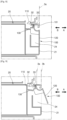
- FIGS. 8 and 9 are schematic cross-sectional views showing an example of the developer cartridge 20 employing a handle formed integrally with a rocker arm.
- FIG. 8 shows a state in which the developer cartridge 20 is located in the mounting position 3a
- FIG. 9 shows a state in which the developer cartridge 20 is located in the removal position 3b.
- a handle 100 is provided with a grip portion 120 that can be gripped by a user.
- the grip portion 120 of the handle 100 in conjunction with the movement of the developer cartridge 20 from the mounting position 3a to the removal position 3b of the developer cartridge 20, may be switched from a first position ( FIG. 8 ) adjacent to a side of the developer cartridge 20, for example, the front portion 21, to a second position ( FIG. 9 ) protruding from the side, for example, the front portion 21, so as to be gripped.
- the grip portion 120 may be located in the sunken portion 24 provided at the front portion 21 and may protrude from the sunken portion 24 at the second position.
- the handle 100 may be installed on the developer cartridge 20 so as to be pivotable around a pivot shaft 101 in the first position and the second position.
- the handle 100 provides a locking portion 110 which is latched to the latching portion 32 provided in the main body 1 at the first position to lock the developer cartridge 20 to the mounting position 3a and released from the latching portion 32 at the second position.
- the locking portion 110 may have a hook shape and the latching portion 32 may have a complementary shape interlocking with the locking portion 110.
- a third elastic member 130 applies elastic force to the handle 5 in a direction of switching to the first position.
- the third elastic member 130 may be implemented in various forms such as a coil spring, a leaf spring, and the like.
- the third elastic member 130 may be implemented by an elastic arm integrally formed with the handle 100 and having one end supported by the front portion 21.
- a tension coil spring is employed as the third elastic member 130.
- the main body 1 may be provided with an interference portion 33 for interfering with the locking portion 110 when the developer cartridge 20 is located at the removal position 3b to hold the handle 100 in the second position.
- the developer cartridge 20 may move from the mounting position 3a to the removal position 3b by the releasing member 6 shown in FIG. 3 .
- the developer cartridge 20 is mounted to the main body 1 and located at the mounting position 3a.
- the handle 100 is located at the first position and the locking portion 110 is latched to the latching portion 32. According to such a configuration, the developer cartridge 20 and the handle 100 are respectively held in the mounting position 3a and the first position in a state where the developer cartridge 20 is mounted to the main body 1.
- the developer cartridge 20 may be removed from the main body 1 in this state. Since the handle 100 is located at the second position, a user may remove the developer cartridge 20 from the main body 1 by pulling the developer cartridge 20 in the removal direction B by holding the grip portion 120 of the handle 100, so that the ease of removal may be improved. When the developer cartridge 20 is completely removed from the main body 1, the handle 100 is returned to the first position by the elastic force of the third elastic member 130.
- a process of mounting the developer cartridge 20 to the main body 1 is a reverse order of the removal process described above.
- the developer cartridge 20 is pushed into the main body 1 in the mounting direction A in accordance with the mounting portion 3.
- the locking portion 110 and the interference portion 33 interfere with each other, and the handle 100 is rotated in a direction opposite the elastic force of the third elastic member 130.
- the handle 100 is returned to the first position by the elastic force of the third elastic member 130, and the locking portion 110 is latched to the latching portion 32 and the developer cartridge 20 is locked to the mounting position 3a.
Landscapes
- Physics & Mathematics (AREA)
- General Physics & Mathematics (AREA)
- Engineering & Computer Science (AREA)
- Computer Vision & Pattern Recognition (AREA)
- Electrophotography Configuration And Component (AREA)
- Dry Development In Electrophotography (AREA)
Description
- A printer using an electrophotographic method is a printer that supplies toner to an electrostatic latent image formed on a photoconductor to form a visible toner image on the photoconductor, transfers the toner image to a printing medium via an intermediate transfer medium or directly to a printing medium, and then fixes the transferred toner image on the printing medium.
- The toner is a consumable developer. For example, the printer employs a structure capable of replenishing the developer. For example, the developer may be accommodated in a developer cartridge, and the developer cartridge may be removably mounted to a main body of the printer. When the developer accommodated in the developer cartridge is exhausted, the developer cartridge is removed from the main body of the printer, and a new developer cartridge may be mounted to the main body.
US2012195628A1 relates to an image forming apparatus including a cartridge holder that is movable between an outer position and an inner position relative to the apparatus main body;EP2919075A1 relates to a cartridge that is attached to or detached from a main body of an image forming apparatus;JP2003241615A -
-
FIG. 1 is a configuration diagram of an example of an electrophotographic printer; -
FIG. 2 is a perspective view of an example of an electrophotographic printer showing mounting/removal of a developer cartridge; -
FIGS. 3 to 5 are views of a process in which a developer cartridge moves from a mounting position to a removal position, whereinFIG. 3 shows a state in which the developer cartridge is located in the mounting position,FIG. 4 shows a state in which locking of the developer cartridge is released, andFIG. 5 shows a state in which the developer cartridge is located in the removal position; -
FIG. 6 shows a behavior of a rocker arm in a process of switching a handle from a second position to a first position; -
FIG. 7 shows various forms of a handle; and -
FIGS. 8 and 9 are cross-sectional views showing an example of a developer cartridge employing a handle formed integrally with a rocker arm, whereinFIG. 8 shows a state in which the developer cartridge is located in a mounting position, andFIG. 9 shows a state in which the developer cartridge is located in a removal position. - An example embodiment of a printer includes: a main body including a printing unit to print an image on a printing medium and including an interior space to accommodate a removable developer cartridge that includes a developer to be supplied to the printing unit; a releasing member, provided in a rear portion of the interior space of the main body, that when the developer cartridge is installed in the main body and is to be removed from the main body, is to rotate so as to move the developer cartridge in a removal direction to remove the developer cartridge from the main body; and a latching portion, provided in a front portion of the interior space of the main body, that when the developer cartridge is installed in the main body is latched to a portion of the developer cartridge so that a handle of the developer cartridge is maintained in a first position, and when the developer cartridge is removed from the main body the latching portion is unlatched from the portion of the developer cartridge so that the handle is concurrently moved to a second position to protrude from the developer cartridge.
- The developer cartridge may include: a rocker arm provided on the developer cartridge to switch between a third position at which the rocker arm holds the developer cartridge at a mounting position where the developer cartridge is locked to the main body and holds the handle at the first position, and a fourth position at which the rocker arm allows the developer cartridge to move to a removal position where the developer cartridge is unlocked from the main body and allows the handle to be switched to the second position; a first elastic member to apply an elastic force to the rocker arm in a direction so that the rocker arm is held in the third position; and a second elastic member to apply an elastic force to the handle in a direction to switch the handle to the second position.
- The rocker arm may be switched from the third position to the fourth position by the movement of the developer cartridge to the removal position.
- The rocker arm may have a first locking portion and a second locking portion, the portion of the developer cartridge may correspond to the first locking portion and the latching portion may be to latch to the first locking portion when the rocker arm is located at the third position, and the handle may be provided with a handle latching portion to latch the second locking portion when the rocker arm is located at the third position.
- The rocker arm may include an intermediate position between the third position and the fourth position, where the latching of the first locking portion and the latching portion is maintained and the latching of the second locking portion and the handle latching portion is released.
- A first latching distance between the first locking portion and the latching portion may be greater than a second latching distance between the second locking portion and the handle latching portion.
- The handle may include a locking portion, and the portion of the developer cartridge may correspond to the locking portion and the locking portion may be latched to the latching portion when the handle is at the first position to lock the developer cartridge to a mounting position where the developer cartridge is locked to the main body and the locking portion may be released from the latching portion when the handle is at the second position.
- The developer cartridge may include an elastic member to apply an elastic force to the handle in a direction to switch the handle to the first position.
- The main body may include an interference portion to interfere with the locking portion to hold the handle in the second position when the developer cartridge moves from the mounting position to a removal position where the developer cartridge is unlocked from the main body.
- An example developer cartridge, which is installable in a printer, includes: a body having a rear side and a front side; a handle, provided on the front side of the body, movable between a first position at which the handle is adjacent to the front side of the body to a second position at which the handle protrudes from the front side of the body; and a rocker arm provided in the developer cartridge to move from a third position, at which the developer cartridge is locked to a main body of the printer when the developer cartridge is installed in the main body, to a fourth position, at which the developer cartridge is unlocked from the main body when the developer cartridge is removed from the main body by a force applied to the rear side of the body in a rear to front direction of the body,
- The rocker arm is to hold the handle in the first position when the rocker arm is in the third position and is to allow the handle to move from the first position to the second position when the rocker arm moves from the third position to the fourth position.
- The developer cartridge may further include: a first elastic member to apply an elastic force to the rocker arm in a direction so that the rocker arm is held in the third position; and a second elastic member to apply an elastic force to the handle in a direction to switch the handle to the second position. The rocker arm may have a first locking portion and a second locking portion, the main body of the printer may be provided with a first latching portion to latch the first locking portion when the rocker arm is located at the third position, and the developer cartridge may be provided with a second latching portion to latch the second locking portion when the rocker arm is located at the third position.
- A first latching distance between the first locking portion and the first latching portion may be greater than a second latching distance between the second locking portion and the second latching portion.
- The rocker arm and the handle may be integrally formed, and the developer cartridge may further include: an elastic member to apply an elastic force to the handle in a direction to switch the handle to the first position.
- The main body of the printer may include an interference portion to interfere with the rocker arm to hold the handle in the second position when the developer cartridge is moved from a mounting position where the developer cartridge is locked to the main body to a removal position where the developer cartridge is unlocked from the main body.
- The force applied to the rear side of the body of the developer cartridge may be applied by a releasing member provided in the main body of the printer to push the developer cartridge in a removal direction to switch the rocker arm from the third position to the fourth position.
-
FIG. 1 is a configuration diagram of an example of an electrophotographic printer. Referring toFIG. 1 , the electrophotographic printer includes amain body 1 of the electrophotographic printer and adeveloper cartridge 20 which is removably mounted to themain body 1. Thedeveloper cartridge 20 is also referred to as a 'toner cartridge'. Themain body 1 includes aprinting unit 2 for printing an image on a printing medium P by an electrophotographic method. Theprinting unit 2 of the example prints an image on the printing medium P by the electrophotographic method. Theprinting unit 2 may include a developingunit 10, anexposure unit 50, a transfer unit, and afixing unit 80. - The electrophotographic printer may include the
developer cartridge 20 containing a developer. Thedeveloper cartridge 20 accommodates the developer to be supplied to theprinting unit 2. Thedeveloper cartridge 20 is mounted to themain body 1 and connected to the developingunit 10 and the developer accommodated in thedeveloper cartridge 20 is supplied to the developingunit 10. Thedeveloper cartridge 20 may be connected to, for example, the developingunit 10 via asupply duct 40. Although not shown in the drawings, a supply unit for regulating a supply amount of the developer may be interposed between thedeveloper cartridge 20 and the developingunit 10. Although not shown in the drawings, thedeveloper cartridge 20 may have a carrying member for carrying the developer contained therein to thesupply duct 40. The carrying member may be connected to a driving motor (not shown) provided in themain body 1 when thedeveloper cartridge 20 is mounted to themain body 1. - The developing
unit 10 supplies toner to an electrostatic latent image formed on aphotosensitive drum 14 to develop the electrostatic latent image into a visible toner image. The developingunit 10 may include thephotosensitive drum 14 on which the electrostatic latent image is formed and a developingroller 13 for supplying toner to the electrostatic latent image to develop the electrostatic latent image into a visible toner image. Thephotosensitive drum 14 is an example of a photoconductor, and may include a conductive metal pipe and a photosensitive layer formed on the periphery thereof. Acharging roller 15 is an example of a charger that charges thephotosensitive drum 14 to have a uniform surface potential. Instead of the chargingroller 15, a charging brush, a corona charger, or the like may be employed. Although not shown in the figure, the developingunit 10 may further include a charging roller cleaner for removing foreign materials such as a developer or dust adhered to thecharging roller 15, acleaning member 17 for removing a developer remaining on a surface of thephotosensitive drum 14 after an intermediate transfer process described later below, and a regulating member (not shown) for regulating the amount of a developer supplied to a developing area where thephotosensitive drum 14 and the developingroller 13 face each other. Thecleaning member 17 may be, for example, a cleaning blade that contacts the surface of thephotosensitive drum 14 to scrape a developer. Although not shown in the drawings, thecleaning member 17 may be a cleaning brush that contacts a surface of thephotosensitive drum 14 while rotating and scrapes a developer. - A one-component developing system using toner as a developer may be classified into a contact developing method in which the developing
roller 13 and thephotosensitive drum 14 are rotated in contact with each other and a non-contact developing method in which the developingroller 13 and thephotosensitive drum 14 are rotated and located so as to be spaced apart from each other by tens to hundreds of microns. - In the case of a two-component development system using toner and a carrier as a developer, the developing
roller 13 is located so as to be spaced apart from thephotosensitive drum 14 by tens to hundreds of microns. Although not shown in the drawings, the developingroller 13 may include a hollow cylindrical sleeve to be rotated and a magnetic roller fixedly arranged in the sleeve. The toner is attached to a surface of the magnetic carrier. The magnetic carrier is attached to a surface of the developingroller 13 and carried to a developing area where thephotosensitive drum 14 and the developingroller 13 face each other. The toner is supplied to thephotosensitive drum 14 by a developing bias voltage applied between the developingroller 13 and thephotosensitive drum 14 to develop the electrostatic latent image formed on a surface of thephotosensitive drum 14 into a visible toner image. - In the example, a two-component developing method is employed. The inside of the developing
unit 10 may be divided into astirring chamber 10a and a developingchamber 10b by abarrier wall 11. A developer supplied from thedeveloper cartridge 20 may be flow into, for example, thestirring chamber 10a. Astirrer 12a axially carries the developer inside the stirringchamber 10a. Astirrer 12b carries the developer inside the developingchamber 10b in a direction opposite the carrying direction of thestirrer 12a. The pair ofstirrers chamber 10a and the developingchamber 10b with each other are provided on both sides of thebarrier wall 11 in an axial direction, respectively, whereby the developer is circulated inside the stirringchambers stirrers stirrers roller 13 supplies toner inside the developingchamber 10b to thephotosensitive drum 14 to develop the electrostatic latent image formed on the surface of thephotosensitive drum 14 into a visible toner image. - In a case of the one-component developing method, the
developer cartridge 20 receives toner as a developer. In a case of the two-component developing method, toner may be accommodated in thedeveloper cartridge 20, or toner and a carrier may be accommodated. When a trickle developing method is employed, toner and a carrier may be accommodated in thedeveloper cartridge 20. - The
exposure unit 50 irradiates light modulated corresponding to image information onto thephotosensitive drum 14 to form the electrostatic latent image on thephotosensitive drum 14. Examples of theexposure unit 50 include a laser scanning unit (LSU) using a laser diode as a light source or a light emitting diode (LED) exposure unit using an LED as a light source. - The transfer unit transfers a toner image formed on the
photosensitive drum 14 to the printing medium P. The transfer unit may include atransfer roller 70. Thetransfer roller 70 is located facing thephotosensitive drum 14. A transfer bias voltage for transferring the toner image formed on thephotosensitive drum 14 to the printing medium P is applied to thetransfer roller 70. - The fixing
unit 80 applies heat and/or pressure to the toner image transferred to the printing medium P to fix the toner image on the printing medium P. A configuration of the fixingunit 80 is not limited to the example shown inFIG. 1 . - According to the above configuration, the
exposure unit 50 scans thephotosensitive drum 14 with light modulated corresponding to image information to be printed, thereby forming the electrostatic latent image on thephotosensitive drum 14. The electrostatic latent image on thephotosensitive drum 14 is developed into a visible toner image by the developer supplied from thedeveloper cartridge 20 to the developingunit 10. The printing medium P mounted to apaper feeding device 90 is carried between thetransfer roller 70 and thephotosensitive drum 14 along apaper feeding path 91. The toner image on thephotosensitive drum 14 is transferred to the printing medium P by the transfer bias voltage applied to thetransfer roller 70. When the printing medium P passes the fixingunit 80, the toner image is fixed to the printing medium P by heat and pressure. The printing medium P to which the toner image is fixed is discharged by adischarge roller 92. - The
developer cartridge 20 is mountable to and removable from themain body 1. When the developer accommodated in thedeveloper cartridge 20 is exhausted, thedeveloper cartridge 20 may be replaced with anew developer cartridge 20. -
FIG. 2 is a perspective view of an example of a printer. Referring toFIG. 2 , themain body 1 of the printer may be provided with a mountingportion 3 to which thedeveloper cartridge 20 is mounted. Adoor 4 opens and closes a part of themain body 1 to mount/remove thedeveloper cartridge 20 to/from themain body 1. As shown inFIG. 2 , the mounting portion(interior space) 3 is exposed when thedoor 4 is in an open position and thedeveloper cartridge 20 may be slid in a mounting direction A and mounted to the mountingportion 3. When the mounting is completed, thedeveloper cartridge 20 reaches a mountingposition 3a where thedeveloper cartridge 20 is locked to themain body 1. - A process of removing the
developer cartridge 20 from themain body 1 may include a process of releasing the locking of thedeveloper cartridge 20. Thedeveloper cartridge 20 is moved to aremoval position 3b slightly moved in a removal direction B from the mountingposition 3a by a releasing member 6 (ofFIG. 3 ) described later below. The locking of thedeveloper cartridge 20 to themain body 1 is released in the process of moving thedeveloper cartridge 20 from the mountingposition 3a to theremoval position 3b. - For example, the releasing
member 6 is provided in a rear portion of the mounting portion(interior space) 3 and pushes thedeveloper cartridge 20 located at the mountingposition 3a to move from the mountingposition 3a to theremoval position 3b. In this state, thedeveloper cartridge 20 may be slid in the removal direction B and removed from themain body 1. A distance between the mountingposition 3a and theremoval position 3b is not particularly limited as long as it can be visually confirmed that thedeveloper cartridge 20 is in a removable state. - As described above, at the mounting
position 3a, thedeveloper cartridge 20 is locked to themain body 1 so that a user cannot arbitrarily remove it. A portion of thedeveloper cartridge 20 facing thedoor 4, for example, afront portion 21, may have no grooves or protrusions that can be held by a user. Release of the locking of thedeveloper cartridge 20 may be performed by driving the releasingmember 6. For example, when a remaining amount of the developer in thedeveloper cartridge 20 reaches a remaining amount as a replacement reference, it is possible to output a replacement signal that a user can perceive to replace thedeveloper cartridge 20 through an output device (not shown) such as a display, a buzzer, a lighting device, or the like. The replacement signal may be, for example, a video signal displayed on a display, a sound signal through a buzzer, an optical signal through a lighting device, or the like. A user may input an operation for requesting replacement of thedeveloper cartridge 20 via an operation panel. A control unit (not shown) may guide a user's operation procedure for replacing thedeveloper cartridge 20, for example, via a display, and a user may replace thedeveloper cartridge 20 in accordance with the guide. In order to prevent an arbitrary replacement of thedeveloper cartridge 20, the operation procedure may include a password input. The control unit operates the releasingmember 6 to push thedeveloper cartridge 20 to theremoval position 3b in the removal direction B in accordance with the user's operation. Then, the locking of thedeveloper cartridge 20 to themain body 1 is released, and thedeveloper cartridge 20 may be removed. - The
developer cartridge 20 includes abody 20a having arear side 20b and a front side(front portion) 21. Thedeveloper cartridge 20 is be provided with ahandle 5. As an example, thehandle 5 is provided at a portion of thedeveloper cartridge 20 facing thedoor 4, for example, thefront portion 21. Thehandle 5, in conjunction with the movement of thedeveloper cartridge 20 from the mountingposition 3a to theremoval position 3b of thedeveloper cartridge 20, may be switched from a first position adjacent to a side of thedeveloper cartridge 20, for example, thefront portion 21, to a second position protruding from the side, for example, thefront portion 21, so as to be gripped. According to such a configuration, when thedeveloper cartridge 20 is located at the mountingposition 3a, thehandle 5 is located at the first position, so that thehandle 5 cannot be gripped. Therefore, arbitrary removal of thedeveloper cartridge 20 may be prevented. Further, when thedeveloper cartridge 20 is located at theremoval position 3b, thehandle 5 is located at the second position where thehandle 5 can be gripped, so that thedeveloper cartridge 20 may be easily removed by holding thehandle 5. - The
release member 6 may apply a force to therear side 20b of thebody 20a of thedeveloper cartridge 20 to push thedeveloper cartridge 20 in the removal direction B. Hereinafter, examples of the releasingmember 6 for moving thedeveloper cartridge 20 from the mountingposition 3a to theremoval position 3b and examples of an interlocking structure of movement of thedeveloper cartridge 20 from the mountingposition 3a to theremoval position 3b and switching of thehandle 5 to the first and second positions will be described. -
FIGS. 3 to 5 are views of a process in which thedeveloper cartridge 20 moves from the mountingposition 3a to theremoval position 3b.FIG. 3 shows a state in which thedeveloper cartridge 20 is located in the mountingposition 3a,FIG. 4 shows a state in which locking of thedeveloper cartridge 20 is released, andFIG. 5 shows a state in which thedeveloper cartridge 20 is located in theremoval position 3b. - Referring to
FIGS. 3 to 5 , the releasingmember 6 may include acam 61 and amotor 62 for rotating thecam 61. Themotor 62 may be a dedicated motor for driving thecam 61. Themotor 62 may be a main motor that drives rotational elements of a printer. In this case, a clutch (not shown) for selectively transmitting rotational force of themotor 62 to thecam 61 may be interposed between themotor 62 and thecam 61. Although not shown in the drawings, the releasingmember 6 may be implemented in various forms such as a linear actuator having a stroke that can push thedeveloper cartridge 20 from the mountingposition 3a to theremoval position 3b. - The
developer cartridge 20 is provided with arocker arm 7. Therocker arm 7 may be switched between a third position (FIG. 3 ) for respectively holding thedeveloper cartridge 20 and thehandle 5 at a mountingposition 3a and the first position and a fourth position (FIG. 4 ) for respectively allowing thedeveloper cartridge 20 and thehandle 5 to be switched to theremoval position 3b and the second position. Therocker arm 7 may be switched from the third position to the fourth position by movement of thedeveloper cartridge 20 from the mountingposition 3a to theremoval position 3b. For example, therocker arm 7 may be installed in thedeveloper cartridge 20 so as to be pivotable to the third and fourth positions around apivot shaft 22. A firstelastic member 81 applies elastic force to therocker arm 7 in a direction held in the third position. The firstelastic member 81 may be implemented in various forms such as a coil spring, a leaf spring, and the like. In the example, a torsion coil spring is employed as the firstelastic member 81. - As an example, the
handle 5 may be installed on thedeveloper cartridge 20 so as to be pivotable around apivot shaft 23 in the first position (FIG. 3 ) and the second position (FIG. 4 ). For example, thefront portion 21 of thedeveloper cartridge 20 may be provided with asunken portion 24, which is sunken in the mounting direction A. Thehandle 5 may be located in thesunken portion 24 at the first position and may be pivoted at the second position so as to protrude from thefront portion 21 by coming out of thesunken portion 24. A secondelastic member 82 applies elastic force to thehandle 5 in a direction of switching to the second position. The secondelastic member 82 may be implemented in various forms such as a coil spring, a leaf spring, and the like. In the example, a torsion coil spring is employed as the secondelastic member 82. The secondelastic member 82 may be implemented by an elastic arm formed integrally with thehandle 5 as shown inFIG. 7 (d) . - Referring to
FIG. 3 , thedeveloper cartridge 20 is mounted to themain body 1 and located at the mountingposition 3a. A bottomdead portion 61a of thecam 61 faces thedeveloper cartridge 20. Therocker arm 7 is located at the third position to hold thedeveloper cartridge 20 in the mounting position and simultaneously hold thehandle 5 in the first position. For example, therocker arm 7 may have afirst locking portion 71 and asecond locking portion 72. Themain body 1 may be provided with a first latching portion(latching portion) 31 for latching thefirst locking portion 71 when therocker arm 7 is located at the third position. Thehandle 5 may be provided with a second latching portion(handle latching portion) 51 for latching thesecond locking portion 72 when therocker arm 7 is located at the third position. The first andsecond locking portions second latching portions second locking portions developer cartridge 20 and thehandle 5 are respectively held in the mountingposition 3a and the first position by therocker arm 7 in a state where thedeveloper cartridge 20 is mounted to themain body 1. - In order to remove the
developer cartridge 20, the control unit drives themotor 62 to rotate thecam 61. Thecam 61 pushes thedeveloper cartridge 20 in the removal direction B. When thedeveloper cartridge 20 is pushed in the removal direction B, reaction force is applied to thefirst locking portion 71 by thefirst latching portion 31 and therocker arm 7 is rotated in the opposite direction of the elastic force of the firstelastic member 81 and located at the fourth position. Then, as shown inFIG. 4 , the latching of thefirst locking portion 71 and thefirst latching portion 31 is released, and the latching of thesecond locking portion 72 and thesecond latching portion 51 is also released. Thehandle 5 is rotated to the second position by the elastic force of the secondelastic member 82. - When the
cam 61 is continuously rotated, thedeveloper cartridge 20 continues to be pushed in the removal direction B. When a topdead portion 61b of thecam 61 faces thedeveloper cartridge 20, thedeveloper cartridge 20 is located at theremoval position 3b as shown inFIG. 5 . Therocker arm 7 is returned to the third position by the elastic force of the firstelastic member 81. The control unit, in preparation for re-mounting of thedeveloper cartridge 20, may rotate thecam 61 until the bottomdead portion 61a faces thedeveloper cartridge 20 as shown by a dashed line inFIG. 5 and may stop thecam 61 at that position. - The
developer cartridge 20 may be removed from themain body 1 in this state. Since thehandle 5 is located at the second position, a user may remove thedeveloper cartridge 20 from themain body 1 by pulling thedeveloper cartridge 20 in the removal direction B by holding thehandle 5, so that the ease of removal may be improved. - A process of mounting the
developer cartridge 20 to themain body 1 is a reverse order of the removal process described above. Thecam 61 is in a state in which the bottomdead portion 61a faces thedeveloper cartridge 20 as shown by the dashed line inFIG. 5 . Thedeveloper cartridge 20 is pushed into themain body 1 in the mounting direction A in accordance with the mountingportion 3. When thedeveloper cartridge 20 reaches the position shown inFIG. 4 through theremoval position 3b, therocker arm 7 is rotated in the opposite direction of the elastic force of the firstelastic member 81 from the third position while thefirst locking portion 71 and thefirst latching portion 31 interfere with each other in the reverse direction. When thedeveloper cartridge 20 reaches the mountingposition 3a shown inFIG. 3 , therocker arm 7 is returned to the third position by the elastic force of the firstelastic member 81, and thefirst locking portion 71 is latched to thefirst latching portion 31 and thedeveloper cartridge 20 is locked to the mountingposition 3a. - The
handle 5 may be located at the second position even after thedeveloper cartridge 20 reaches the mountingposition 3a. In this case, thehandle 5 may be pressed to be switched from the second position to the first position. When thehandle 5 located at the second position is rotated in the first position by being pushed in a direction opposite the elastic force of the secondelastic member 82, therocker arm 7 is slightly rotated in a direction opposite the elastic force of the firstelastic member 81 from the third position while thesecond locking portion 72 and thesecond latching portion 51 interfere with each other in the reverse direction. When thehandle 5 reaches the first position as shown inFIG. 3 , therocker arm 7 is returned to the third position by the elastic force of the firstelastic member 81 and thesecond locking portion 72 is latched to thesecond latching portion 51 so that thehandle 5 is held in the first position. -
FIG. 6 shows a behavior of therocker arm 7 in a process of switching thehandle 5 from the second position to the first position. Referring toFIG. 6 , a first latching distance C1 between thefirst locking portion 71 and thefirst latching portion 31 is greater than a second latching distance C2 between thesecond locking portion 72 and thesecond latching portion 51. Therocker arm 7 may have an intermediate position (a position shown by a dashed line inFIG. 6 ) where latching of thefirst locking portion 71 and thefirst latching portion 31 is maintained between the third position and the fourth position and latching of thesecond locking portion 72 and thesecond latching portion 51 is released. - As described above, in a process of returning the
handle 5 from the second position to the first position, therocker arm 7 is slightly rotated in a direction opposite the elastic force of the firstelastic member 81 from the third position while thesecond locking portion 72 and thesecond latching portion 51 interfere with each other in the reverse direction. Since the first latching distance C1 is greater than the second latching distance C2, as shown by a dashed line inFIG. 6 , the latching of thefirst locking portion 71 and thefirst latching portion 31 is maintained even when the reverse interference between thesecond locking portion 72 and thesecond latching portion 51 becomes maximum. That is, before reaching the fourth position, therocker arm 7 reaches an intermediate position where the reverse interference between thesecond locking portion 72 and thesecond latching portion 51 becomes maximum, and thehandle 5 may be returned from the second position to the first position. Therefore, even when thehandle 5 is switched from the second position to the first position, locking of thedeveloper cartridge 20 to the mountingposition 3a may be maintained. - The form of the
handle 5 and the mode of switching to the first and second positions may vary.FIG. 7 shows various forms of thehandle 5. As shown inFIG. 7 (a) , thehandle 5 may have a size corresponding to a shape of thefront portion 21 of thedeveloper cartridge 20. This configuration may guide a user to push thedeveloper cartridge 20 in the mounting direction A while pressing thehandle 5 when thedeveloper cartridge 20 is mounted to themain body 1. Thehandle 5 may be switched from the second position to the first position by the mounting operation of thedeveloper cartridge 20. Therefore, there is no need to perform an additional operation of pressing thehandle 5 to switch thehandle 5 from the second position to the first position after thedeveloper cartridge 20 reaches the mountingposition 3a, and user convenience may be improved. - As shown in
FIG. 7 (b) , thehandle 5 may be smaller than thefront portion 21 of thedeveloper cartridge 20. When a user removes thedeveloper cartridge 20 from themain body 1 with one hand, the user may drop thedeveloper cartridge 20 without supporting the weight of thedeveloper cartridge 20 as soon as thedeveloper cartridge 20 completely disengages from the mountingportion 3. Such asmall handle 5 is used for pulling thedeveloper cartridge 20 in the removal direction B to remove thedeveloper cartridge 20 from themain body 1 and may guide the user to hold thedeveloper cartridge 20 with the other hand after a certain portion of thedeveloper cartridge 20 is slid out of themain body 1. Accordingly, thedeveloper cartridge 20 may be removed safely, and the risk of breakage due to the dropping of thedeveloper cartridge 20 in the process of removing thedeveloper cartridge 20 may be reduced. - In
FIGS. 7 (a) and (b) , thehandle 5 is rotated in a longitudinal direction to be switched to the first and second positions. As shown inFIG. 7 (d) , thehandle 5 may be rotated in a lateral direction to be switched to the first and second positions. Furthermore, as shown inFIG. 7 (c) , thehandle 5 may move in forward and backward directions, that is, in the mounting direction A and the removal direction B to be switched to the first and second positions. - The
handle 5 and therocker arm 7 may be integrally formed.FIGS. 8 and 9 are schematic cross-sectional views showing an example of thedeveloper cartridge 20 employing a handle formed integrally with a rocker arm.FIG. 8 shows a state in which thedeveloper cartridge 20 is located in the mountingposition 3a, andFIG. 9 shows a state in which thedeveloper cartridge 20 is located in theremoval position 3b. - Referring to
FIGS. 8 and 9 , ahandle 100 is provided with agrip portion 120 that can be gripped by a user. Thegrip portion 120 of thehandle 100, in conjunction with the movement of thedeveloper cartridge 20 from the mountingposition 3a to theremoval position 3b of thedeveloper cartridge 20, may be switched from a first position (FIG. 8 ) adjacent to a side of thedeveloper cartridge 20, for example, thefront portion 21, to a second position (FIG. 9 ) protruding from the side, for example, thefront portion 21, so as to be gripped. For example, at the first position, thegrip portion 120 may be located in thesunken portion 24 provided at thefront portion 21 and may protrude from thesunken portion 24 at the second position. - For example, the
handle 100 may be installed on thedeveloper cartridge 20 so as to be pivotable around apivot shaft 101 in the first position and the second position. Thehandle 100 provides a lockingportion 110 which is latched to the latchingportion 32 provided in themain body 1 at the first position to lock thedeveloper cartridge 20 to the mountingposition 3a and released from the latchingportion 32 at the second position. The lockingportion 110 may have a hook shape and the latchingportion 32 may have a complementary shape interlocking with the lockingportion 110. A thirdelastic member 130 applies elastic force to thehandle 5 in a direction of switching to the first position. The thirdelastic member 130 may be implemented in various forms such as a coil spring, a leaf spring, and the like. The thirdelastic member 130 may be implemented by an elastic arm integrally formed with thehandle 100 and having one end supported by thefront portion 21. In the example, a tension coil spring is employed as the thirdelastic member 130. Themain body 1 may be provided with aninterference portion 33 for interfering with the lockingportion 110 when thedeveloper cartridge 20 is located at theremoval position 3b to hold thehandle 100 in the second position. Although not shown inFIG. 8 , thedeveloper cartridge 20 may move from the mountingposition 3a to theremoval position 3b by the releasingmember 6 shown inFIG. 3 . - Referring to
FIG. 8 , thedeveloper cartridge 20 is mounted to themain body 1 and located at the mountingposition 3a. Thehandle 100 is located at the first position and the lockingportion 110 is latched to the latchingportion 32. According to such a configuration, thedeveloper cartridge 20 and thehandle 100 are respectively held in the mountingposition 3a and the first position in a state where thedeveloper cartridge 20 is mounted to themain body 1. - When the
developer cartridge 20 is pushed in the removal direction B by the releasingmember 6, a reaction force is applied to the lockingportion 110 by the latchingportion 32 and thehandle 100 is rotated in the opposite direction of the elastic force of the thirdelastic member 130 and located at the second position. Then, as shown inFIG. 9 , the latching of the lockingportion 110 and the latchingportion 32 is released. Thedeveloper cartridge 20 is continuously pushed by the releasingmember 6 in the removal direction B to reach theremoval position 3b. The lockingportion 110 is brought into contact with theinterference portion 33. Thus, thehandle 100 is held in the second position. - The
developer cartridge 20 may be removed from themain body 1 in this state. Since thehandle 100 is located at the second position, a user may remove thedeveloper cartridge 20 from themain body 1 by pulling thedeveloper cartridge 20 in the removal direction B by holding thegrip portion 120 of thehandle 100, so that the ease of removal may be improved. When thedeveloper cartridge 20 is completely removed from themain body 1, thehandle 100 is returned to the first position by the elastic force of the thirdelastic member 130. - A process of mounting the
developer cartridge 20 to themain body 1 is a reverse order of the removal process described above. Thedeveloper cartridge 20 is pushed into themain body 1 in the mounting direction A in accordance with the mountingportion 3. When thedeveloper cartridge 20 passes theremoval position 3b, the lockingportion 110 and theinterference portion 33 interfere with each other, and thehandle 100 is rotated in a direction opposite the elastic force of the thirdelastic member 130. When thedeveloper cartridge 20 reaches the mountingposition 3a as shown inFIG. 8 , thehandle 100 is returned to the first position by the elastic force of the thirdelastic member 130, and the lockingportion 110 is latched to the latchingportion 32 and thedeveloper cartridge 20 is locked to the mountingposition 3a. - According to such a configuration, since the
handle 100 is returned to the first position by the operation of mounting thedeveloper cartridge 20 to the mountingportion 3, there is no need for a user to perform additional operations for returning thehandle 100 to the first position. Further, since thehandle 100 also locks thedeveloper cartridge 20 to themain body 1, material cost may be reduced. - It should be understood that the disclosure described herein should be considered in a descriptive sense and is not intended to be limiting. Descriptions of features within each example should be considered as available for other similar features in other examples. Therefore, the scope of the disclosure is defined not by the detailed description of the disclosure but by the appended claims.
Claims (15)
- A printer, comprising:a main body (1) including a printing unit (2) to print an image on a printing medium and including an interior space (3) to accommodate a removable developer cartridge (20) that includes a developer to be supplied to the printing unit (2);characterized in that the printer comprises:a releasing member (6), provided in a rear portion of the interior space (3) of the main body (1), that when the developer cartridge (20) is installed in the main body (1) and is to be removed from the main body (1), is to rotate so as to move the developer cartridge (20) in a removal direction to remove the developer cartridge (20) from the main body (1); anda latching portion (31, 32), provided in a front portion of the interior space (3) of the main body (1), that when the developer cartridge (20) is installed in the main body (1) is latched to a portion of the developer cartridge (20) so that a handle (5, 100) of the developer cartridge (20) is maintained in a first position, and when the developer cartridge (20) is removed from the main body the latching portion (31, 32) is unlatched from the portion of the developer cartridge (20) so that the handle (5, 100) is concurrently moved to a second position to protrude from the developer cartridge (20).
- The printer of claim 1, wherein the developer cartridge (20) includes:a rocker arm (7) provided on the developer cartridge (20) to switch between a third position at which the rocker arm (7) holds the developer cartridge (20) at a mounting position where the developer cartridge (20) is locked to the main body (1) and holds the handle (7) at the first position, and a fourth position at which the rocker arm (7) allows the developer cartridge (20) to move to a removal position where the developer cartridge (20) is unlocked from the main body (1) and allows the handle (5) to be switched to the second position;a first elastic member (81) to apply an elastic force to the rocker arm in a direction so that the rocker arm is held in the third position; anda second elastic member (82) to apply an elastic force to the handle (5) in a direction to switch the handle (5) to the second position.
- The printer of claim 2, wherein the rocker arm (7) is switched from the third position to the fourth position by the movement of the developer cartridge (20) to the removal position.
- The printer of claim 3, whereinthe rocker arm (7) has a first locking portion (71) and a second locking portion (72),the portion of the developer cartridge (20) corresponds to the first locking portion (71) and the latching portion (31) is to latch to the first locking portion (71) when the rocker arm (7) is located at the third position, andthe handle (5) is provided with a handle latching portion (51) to latch the second locking portion (72) when the rocker arm (7) is located at the third position.
- The printer of claim 4, wherein the rocker arm (7) includes an intermediate position between the third position and the fourth position, where the latching of the first locking portion (71) and the latching portion (31) is maintained and the latching of the second locking portion (72) and the handle latching portion (51) is released.
- The printer of claim 5, wherein a first latching distance between the first locking portion (71) and the latching portion (31) is greater than a second latching distance between the second locking portion (72) and the handle latching portion (51).
- The printer of claim 1, whereinthe handle (100) includes a locking portion (110), andthe portion of the developer cartridge (20) corresponds to the locking portion (110) and the locking portion (110) is latched to the latching portion (32) when the handle (100) is at the first position to lock the developer cartridge (20) to a mounting position where the developer cartridge (20) is locked to the main body (1) and the locking portion (110) is released from the latching portion (32) when the handle (100) is at the second position.
- The printer of claim 7, wherein the developer cartridge (20) includes an elastic member to apply an elastic force (130) to the handle (100) in a direction to switch the handle (100) to the first position.
- The printer of claim 8, wherein the main body (1) includes an interference portion (33) to interfere with the locking portion (110) to hold the handle (100) in the second position when the developer cartridge (20) moves from the mounting position to a removal position where the developer cartridge (20) is unlocked from the main body (1).
- A developer cartridge (20) which is installable in a printer, the developer cartridge comprising:a body (20a) having a rear side (20b) and a front side (21);a handle (5, 100), provided on the front side (21) of the body (20a), movable between a first position at which the handle (5, 100) is adjacent to the front side (21) of the body (20a) to a second position at which the handle (5) protrudes from the front side (21) of the body (20a); anda rocker arm provided in the developer cartridge (20) to move from a third position, at which the developer cartridge (20) is locked to a main body (1) of the printer when the developer cartridge (20) is installed in the main body (1), to a fourth position, at which the developer cartridge (20) is unlocked from the main body (1) when the developer cartridge (20) is removed from the main body (1) by a force applied to the rear side (20b) of the body (20a) in a rear to front direction ofcharacterized in that the rocker arm is to hold the handle (5, 100) in the first position when the rocker arm is in the third position and is to allow the handle (5, 100) to move from the first position to the second position when the rocker arm moves from the third position to the fourth position.
- The developer cartridge (20) of claim 10, further comprising:a first elastic member (81) to apply an elastic force to the rocker arm (7) in a direction so that the rocker arm is held in the third position; anda second elastic member (82) to apply an elastic force to the handle (5) in a direction to switch the handle (5) to the second position,whereinthe rocker arm (7) has a first locking portion (71) and a second locking portion (72),the main body (1) of the printer is provided with a first latching portion (31) to latch the first locking portion (71) when the rocker arm (7) is located at the third position, andthe developer cartridge (20) is provided with a second latching portion (51) to latch the second locking portion (72) when the rocker arm (7) is located at the third position.
- The developer cartridge (20) of claim 11, wherein a first latching distance between the first locking portion (71) and the first latching portion (31) is greater than a second latching distance between the second locking portion (72) and the second latching portion (51).
- The developer cartridge (20) of claim 10, wherein the rocker arm and the handle (100) are integrally formed, and
the developer cartridge (20) further comprises:
an elastic member (130) to apply an elastic force to the handle (100) in a direction to switch the handle (100) to the first position. - The developer cartridge of claim 13, wherein the main body (1) of the printer includes an interference portion (33) to interfere with the rocker arm to hold the handle (100) in the second position when the developer cartridge (20) is moved from a mounting position where the developer cartridge (20) is locked to the main body (1) to a removal position where the developer cartridge (20) is unlocked from the main body (1).
- The developer cartridge of claim 11, wherein the force applied to the rear side (20b) of the body (20a) of the developer cartridge (20) is applied by a releasing member (6) provided in the main body (1) of the printer to push the developer cartridge (20) in a removal direction to switch the rocker arm from the third position to the fourth position.
Applications Claiming Priority (2)
| Application Number | Priority Date | Filing Date | Title |
|---|---|---|---|
| KR1020180060633A KR20190135317A (en) | 2018-05-28 | 2018-05-28 | structure for protruding handle to release developer cartridge |
| PCT/KR2018/012078 WO2019231059A1 (en) | 2018-05-28 | 2018-10-15 | Structure for protruding handle to release developer cartridge |
Publications (3)
| Publication Number | Publication Date |
|---|---|
| EP3710892A1 EP3710892A1 (en) | 2020-09-23 |
| EP3710892A4 EP3710892A4 (en) | 2021-06-23 |
| EP3710892B1 true EP3710892B1 (en) | 2023-05-10 |
Family
ID=68697620
Family Applications (1)
| Application Number | Title | Priority Date | Filing Date |
|---|---|---|---|
| EP18920625.3A Active EP3710892B1 (en) | 2018-05-28 | 2018-10-15 | Structure for protruding handle to release developer cartridge |
Country Status (5)
| Country | Link |
|---|---|
| US (1) | US11262688B2 (en) |
| EP (1) | EP3710892B1 (en) |
| KR (1) | KR20190135317A (en) |
| CN (1) | CN111989623B (en) |
| WO (1) | WO2019231059A1 (en) |
Families Citing this family (10)
| Publication number | Priority date | Publication date | Assignee | Title |
|---|---|---|---|---|
| KR20200107454A (en) * | 2019-03-08 | 2020-09-16 | 휴렛-팩커드 디벨롭먼트 컴퍼니, 엘.피. | Structure to selectively expose grip portion of toner cartridge |
| US11287770B2 (en) | 2019-12-11 | 2022-03-29 | Lexmark International, Inc. | Toner cartridge latching |
| US11307528B2 (en) * | 2020-05-26 | 2022-04-19 | Kyocera Document Solutions Inc. | Image forming apparatus having a locking mechanism for a unit |
| KR20210153283A (en) * | 2020-06-10 | 2021-12-17 | 휴렛-팩커드 디벨롭먼트 컴퍼니, 엘.피. | toner cartridge having front cover |
| KR20220005192A (en) | 2020-07-06 | 2022-01-13 | 휴렛-팩커드 디벨롭먼트 컴퍼니, 엘.피. | toner cartridge having front cover |
| KR20230057223A (en) | 2021-10-21 | 2023-04-28 | 휴렛-팩커드 디벨롭먼트 컴퍼니, 엘.피. | unlocking toner cartridge by click operation |
| JP7799425B2 (en) * | 2021-10-22 | 2026-01-15 | キヤノン株式会社 | Image forming device |
| JP7750071B2 (en) * | 2021-12-08 | 2025-10-07 | 沖電気工業株式会社 | Developing device and image forming apparatus |
| JP7781657B2 (en) * | 2022-01-28 | 2025-12-08 | キヤノン株式会社 | Image forming device |
| KR20240058564A (en) * | 2022-10-26 | 2024-05-07 | 휴렛-팩커드 디벨롭먼트 컴퍼니, 엘.피. | printer device for preventing arbitrary toner cartridge removal |
Family Cites Families (15)
| Publication number | Priority date | Publication date | Assignee | Title |
|---|---|---|---|---|
| JP3320038B2 (en) | 1999-08-03 | 2002-09-03 | 新潟富士ゼロックス製造株式会社 | cartridge |
| JP4886127B2 (en) | 2001-09-13 | 2012-02-29 | キヤノン株式会社 | Cartridge and electrophotographic image forming apparatus |
| JP2003241615A (en) | 2002-02-19 | 2003-08-29 | Canon Inc | Fixing device and image forming device |
| KR100601681B1 (en) * | 2004-05-29 | 2006-07-14 | 삼성전자주식회사 | Electrophotographic image forming apparatus |
| JP4696613B2 (en) | 2005-03-16 | 2011-06-08 | ブラザー工業株式会社 | ink cartridge |
| JP5144367B2 (en) | 2008-05-19 | 2013-02-13 | シャープ株式会社 | Process cartridge and image processing apparatus including the same |
| JP2011123250A (en) * | 2009-12-10 | 2011-06-23 | Canon Inc | Cartridge and image forming apparatus |
| JP2012155266A (en) * | 2011-01-28 | 2012-08-16 | Brother Ind Ltd | Image forming device |
| JP2014109599A (en) * | 2012-11-30 | 2014-06-12 | Canon Inc | Process cartridge and electrophotographic image forming apparatus |
| KR101474305B1 (en) * | 2013-01-24 | 2014-12-18 | 삼성전자주식회사 | Electrophotographic image forming apparatus and development cartridge |
| KR101585058B1 (en) * | 2014-03-12 | 2016-01-13 | 삼성전자주식회사 | Cartridge and electrophotographic image forming apparatus using the same |
| JP6396235B2 (en) | 2015-02-23 | 2018-09-26 | シャープ株式会社 | Image forming apparatus |
| KR20160143391A (en) * | 2015-06-05 | 2016-12-14 | 에스프린팅솔루션 주식회사 | Developer cartridge and electrophotographic image forming apparatus using the same |
| KR101649277B1 (en) * | 2015-12-18 | 2016-08-18 | 삼성전자주식회사 | Cartridge and electrophotographic image forming apparatus using the same |
| JP6946686B2 (en) * | 2017-03-17 | 2021-10-06 | ブラザー工業株式会社 | Process cartridge |
-
2018
- 2018-05-28 KR KR1020180060633A patent/KR20190135317A/en not_active Withdrawn
- 2018-10-15 CN CN201880092049.0A patent/CN111989623B/en not_active Expired - Fee Related
- 2018-10-15 US US17/050,600 patent/US11262688B2/en not_active Expired - Fee Related
- 2018-10-15 EP EP18920625.3A patent/EP3710892B1/en active Active
- 2018-10-15 WO PCT/KR2018/012078 patent/WO2019231059A1/en not_active Ceased
Also Published As
| Publication number | Publication date |
|---|---|
| KR20190135317A (en) | 2019-12-06 |
| CN111989623A (en) | 2020-11-24 |
| WO2019231059A1 (en) | 2019-12-05 |
| CN111989623B (en) | 2023-06-06 |
| EP3710892A1 (en) | 2020-09-23 |
| EP3710892A4 (en) | 2021-06-23 |
| US11262688B2 (en) | 2022-03-01 |
| US20210240127A1 (en) | 2021-08-05 |
Similar Documents
| Publication | Publication Date | Title |
|---|---|---|
| US11262688B2 (en) | Structure for protruding handle to release developer cartridge | |
| JP6602409B2 (en) | Image forming apparatus | |
| JP4995211B2 (en) | Electrophotographic image forming apparatus | |
| EP1600826B1 (en) | Electrophotographic photosensitive drum, process cartridge and electrophotographic image forming apparatus | |
| JP4882517B2 (en) | Process unit and image forming apparatus | |
| US8571440B2 (en) | Image forming apparatus with cartridge supporting member and preventing member for preventing movement of cartridge supporting member | |
| US9046871B2 (en) | Process cartridge, main cartridge, sub cartridge, and image forming apparatus | |
| US11698602B2 (en) | Toner cartridge having front cover | |
| US11199791B2 (en) | Structure to selectively expose grip portion of toner cartridge | |
| JP2015232690A (en) | Image forming apparatus |
Legal Events
| Date | Code | Title | Description |
|---|---|---|---|
| STAA | Information on the status of an ep patent application or granted ep patent |
Free format text: STATUS: THE INTERNATIONAL PUBLICATION HAS BEEN MADE |
|
| PUAI | Public reference made under article 153(3) epc to a published international application that has entered the european phase |
Free format text: ORIGINAL CODE: 0009012 |
|
| STAA | Information on the status of an ep patent application or granted ep patent |
Free format text: STATUS: REQUEST FOR EXAMINATION WAS MADE |
|
| 17P | Request for examination filed |
Effective date: 20200618 |
|
| AK | Designated contracting states |
Kind code of ref document: A1 Designated state(s): AL AT BE BG CH CY CZ DE DK EE ES FI FR GB GR HR HU IE IS IT LI LT LU LV MC MK MT NL NO PL PT RO RS SE SI SK SM TR |
|
| AX | Request for extension of the european patent |
Extension state: BA ME |
|
| A4 | Supplementary search report drawn up and despatched |
Effective date: 20210526 |
|
| RIC1 | Information provided on ipc code assigned before grant |
Ipc: G03G 21/16 20060101AFI20210519BHEP Ipc: G03G 21/18 20060101ALI20210519BHEP Ipc: G03G 15/08 20060101ALI20210519BHEP |
|
| DAV | Request for validation of the european patent (deleted) | ||
| DAX | Request for extension of the european patent (deleted) | ||
| GRAP | Despatch of communication of intention to grant a patent |
Free format text: ORIGINAL CODE: EPIDOSNIGR1 |
|
| STAA | Information on the status of an ep patent application or granted ep patent |
Free format text: STATUS: GRANT OF PATENT IS INTENDED |
|
| INTG | Intention to grant announced |
Effective date: 20230120 |
|
| GRAS | Grant fee paid |
Free format text: ORIGINAL CODE: EPIDOSNIGR3 |
|
| GRAA | (expected) grant |
Free format text: ORIGINAL CODE: 0009210 |
|
| STAA | Information on the status of an ep patent application or granted ep patent |
Free format text: STATUS: THE PATENT HAS BEEN GRANTED |
|
| AK | Designated contracting states |
Kind code of ref document: B1 Designated state(s): AL AT BE BG CH CY CZ DE DK EE ES FI FR GB GR HR HU IE IS IT LI LT LU LV MC MK MT NL NO PL PT RO RS SE SI SK SM TR |
|
| REG | Reference to a national code |
Ref country code: GB Ref legal event code: FG4D |
|
| REG | Reference to a national code |
Ref country code: AT Ref legal event code: REF Ref document number: 1567291 Country of ref document: AT Kind code of ref document: T Effective date: 20230515 Ref country code: CH Ref legal event code: EP |
|
| REG | Reference to a national code |
Ref country code: DE Ref legal event code: R096 Ref document number: 602018049881 Country of ref document: DE |
|
| REG | Reference to a national code |
Ref country code: NL Ref legal event code: FP Ref country code: IE Ref legal event code: FG4D |
|
| REG | Reference to a national code |
Ref country code: LT Ref legal event code: MG9D |
|
| REG | Reference to a national code |
Ref country code: AT Ref legal event code: MK05 Ref document number: 1567291 Country of ref document: AT Kind code of ref document: T Effective date: 20230510 |
|
| PG25 | Lapsed in a contracting state [announced via postgrant information from national office to epo] |
Ref country code: SE Free format text: LAPSE BECAUSE OF FAILURE TO SUBMIT A TRANSLATION OF THE DESCRIPTION OR TO PAY THE FEE WITHIN THE PRESCRIBED TIME-LIMIT Effective date: 20230510 Ref country code: PT Free format text: LAPSE BECAUSE OF FAILURE TO SUBMIT A TRANSLATION OF THE DESCRIPTION OR TO PAY THE FEE WITHIN THE PRESCRIBED TIME-LIMIT Effective date: 20230911 Ref country code: NO Free format text: LAPSE BECAUSE OF FAILURE TO SUBMIT A TRANSLATION OF THE DESCRIPTION OR TO PAY THE FEE WITHIN THE PRESCRIBED TIME-LIMIT Effective date: 20230810 Ref country code: ES Free format text: LAPSE BECAUSE OF FAILURE TO SUBMIT A TRANSLATION OF THE DESCRIPTION OR TO PAY THE FEE WITHIN THE PRESCRIBED TIME-LIMIT Effective date: 20230510 Ref country code: AT Free format text: LAPSE BECAUSE OF FAILURE TO SUBMIT A TRANSLATION OF THE DESCRIPTION OR TO PAY THE FEE WITHIN THE PRESCRIBED TIME-LIMIT Effective date: 20230510 |
|
| PGFP | Annual fee paid to national office [announced via postgrant information from national office to epo] |
Ref country code: NL Payment date: 20230922 Year of fee payment: 6 Ref country code: GB Payment date: 20230920 Year of fee payment: 6 |
|
| PG25 | Lapsed in a contracting state [announced via postgrant information from national office to epo] |
Ref country code: RS Free format text: LAPSE BECAUSE OF FAILURE TO SUBMIT A TRANSLATION OF THE DESCRIPTION OR TO PAY THE FEE WITHIN THE PRESCRIBED TIME-LIMIT Effective date: 20230510 Ref country code: PL Free format text: LAPSE BECAUSE OF FAILURE TO SUBMIT A TRANSLATION OF THE DESCRIPTION OR TO PAY THE FEE WITHIN THE PRESCRIBED TIME-LIMIT Effective date: 20230510 Ref country code: LV Free format text: LAPSE BECAUSE OF FAILURE TO SUBMIT A TRANSLATION OF THE DESCRIPTION OR TO PAY THE FEE WITHIN THE PRESCRIBED TIME-LIMIT Effective date: 20230510 Ref country code: LT Free format text: LAPSE BECAUSE OF FAILURE TO SUBMIT A TRANSLATION OF THE DESCRIPTION OR TO PAY THE FEE WITHIN THE PRESCRIBED TIME-LIMIT Effective date: 20230510 Ref country code: IS Free format text: LAPSE BECAUSE OF FAILURE TO SUBMIT A TRANSLATION OF THE DESCRIPTION OR TO PAY THE FEE WITHIN THE PRESCRIBED TIME-LIMIT Effective date: 20230910 Ref country code: HR Free format text: LAPSE BECAUSE OF FAILURE TO SUBMIT A TRANSLATION OF THE DESCRIPTION OR TO PAY THE FEE WITHIN THE PRESCRIBED TIME-LIMIT Effective date: 20230510 Ref country code: GR Free format text: LAPSE BECAUSE OF FAILURE TO SUBMIT A TRANSLATION OF THE DESCRIPTION OR TO PAY THE FEE WITHIN THE PRESCRIBED TIME-LIMIT Effective date: 20230811 |
|
| PGFP | Annual fee paid to national office [announced via postgrant information from national office to epo] |
Ref country code: FR Payment date: 20230920 Year of fee payment: 6 |
|
| PG25 | Lapsed in a contracting state [announced via postgrant information from national office to epo] |
Ref country code: FI Free format text: LAPSE BECAUSE OF FAILURE TO SUBMIT A TRANSLATION OF THE DESCRIPTION OR TO PAY THE FEE WITHIN THE PRESCRIBED TIME-LIMIT Effective date: 20230510 |
|
| PG25 | Lapsed in a contracting state [announced via postgrant information from national office to epo] |
Ref country code: SK Free format text: LAPSE BECAUSE OF FAILURE TO SUBMIT A TRANSLATION OF THE DESCRIPTION OR TO PAY THE FEE WITHIN THE PRESCRIBED TIME-LIMIT Effective date: 20230510 |
|
| PG25 | Lapsed in a contracting state [announced via postgrant information from national office to epo] |
Ref country code: SM Free format text: LAPSE BECAUSE OF FAILURE TO SUBMIT A TRANSLATION OF THE DESCRIPTION OR TO PAY THE FEE WITHIN THE PRESCRIBED TIME-LIMIT Effective date: 20230510 Ref country code: SK Free format text: LAPSE BECAUSE OF FAILURE TO SUBMIT A TRANSLATION OF THE DESCRIPTION OR TO PAY THE FEE WITHIN THE PRESCRIBED TIME-LIMIT Effective date: 20230510 Ref country code: RO Free format text: LAPSE BECAUSE OF FAILURE TO SUBMIT A TRANSLATION OF THE DESCRIPTION OR TO PAY THE FEE WITHIN THE PRESCRIBED TIME-LIMIT Effective date: 20230510 Ref country code: EE Free format text: LAPSE BECAUSE OF FAILURE TO SUBMIT A TRANSLATION OF THE DESCRIPTION OR TO PAY THE FEE WITHIN THE PRESCRIBED TIME-LIMIT Effective date: 20230510 Ref country code: DK Free format text: LAPSE BECAUSE OF FAILURE TO SUBMIT A TRANSLATION OF THE DESCRIPTION OR TO PAY THE FEE WITHIN THE PRESCRIBED TIME-LIMIT Effective date: 20230510 Ref country code: CZ Free format text: LAPSE BECAUSE OF FAILURE TO SUBMIT A TRANSLATION OF THE DESCRIPTION OR TO PAY THE FEE WITHIN THE PRESCRIBED TIME-LIMIT Effective date: 20230510 |
|
| PGFP | Annual fee paid to national office [announced via postgrant information from national office to epo] |
Ref country code: DE Payment date: 20230920 Year of fee payment: 6 |
|
| REG | Reference to a national code |
Ref country code: DE Ref legal event code: R097 Ref document number: 602018049881 Country of ref document: DE |
|
| PLBE | No opposition filed within time limit |
Free format text: ORIGINAL CODE: 0009261 |
|
| STAA | Information on the status of an ep patent application or granted ep patent |
Free format text: STATUS: NO OPPOSITION FILED WITHIN TIME LIMIT |
|
| 26N | No opposition filed |
Effective date: 20240213 |
|
| PG25 | Lapsed in a contracting state [announced via postgrant information from national office to epo] |
Ref country code: SI Free format text: LAPSE BECAUSE OF FAILURE TO SUBMIT A TRANSLATION OF THE DESCRIPTION OR TO PAY THE FEE WITHIN THE PRESCRIBED TIME-LIMIT Effective date: 20230510 |
|
| PG25 | Lapsed in a contracting state [announced via postgrant information from national office to epo] |
Ref country code: SI Free format text: LAPSE BECAUSE OF FAILURE TO SUBMIT A TRANSLATION OF THE DESCRIPTION OR TO PAY THE FEE WITHIN THE PRESCRIBED TIME-LIMIT Effective date: 20230510 Ref country code: IT Free format text: LAPSE BECAUSE OF FAILURE TO SUBMIT A TRANSLATION OF THE DESCRIPTION OR TO PAY THE FEE WITHIN THE PRESCRIBED TIME-LIMIT Effective date: 20230510 Ref country code: MC Free format text: LAPSE BECAUSE OF FAILURE TO SUBMIT A TRANSLATION OF THE DESCRIPTION OR TO PAY THE FEE WITHIN THE PRESCRIBED TIME-LIMIT Effective date: 20230510 |
|
| REG | Reference to a national code |
Ref country code: CH Ref legal event code: PL |
|
| REG | Reference to a national code |
Ref country code: BE Ref legal event code: MM Effective date: 20231031 |
|
| PG25 | Lapsed in a contracting state [announced via postgrant information from national office to epo] |
Ref country code: LU Free format text: LAPSE BECAUSE OF NON-PAYMENT OF DUE FEES Effective date: 20231015 |
|
| PG25 | Lapsed in a contracting state [announced via postgrant information from national office to epo] |
Ref country code: LU Free format text: LAPSE BECAUSE OF NON-PAYMENT OF DUE FEES Effective date: 20231015 |
|
| PG25 | Lapsed in a contracting state [announced via postgrant information from national office to epo] |
Ref country code: CH Free format text: LAPSE BECAUSE OF NON-PAYMENT OF DUE FEES Effective date: 20231031 |
|
| PG25 | Lapsed in a contracting state [announced via postgrant information from national office to epo] |
Ref country code: CH Free format text: LAPSE BECAUSE OF NON-PAYMENT OF DUE FEES Effective date: 20231031 |
|
| PG25 | Lapsed in a contracting state [announced via postgrant information from national office to epo] |
Ref country code: BE Free format text: LAPSE BECAUSE OF NON-PAYMENT OF DUE FEES Effective date: 20231031 |
|
| PG25 | Lapsed in a contracting state [announced via postgrant information from national office to epo] |
Ref country code: IE Free format text: LAPSE BECAUSE OF NON-PAYMENT OF DUE FEES Effective date: 20231015 |
|
| PG25 | Lapsed in a contracting state [announced via postgrant information from national office to epo] |
Ref country code: IE Free format text: LAPSE BECAUSE OF NON-PAYMENT OF DUE FEES Effective date: 20231015 |
|
| PG25 | Lapsed in a contracting state [announced via postgrant information from national office to epo] |
Ref country code: BG Free format text: LAPSE BECAUSE OF FAILURE TO SUBMIT A TRANSLATION OF THE DESCRIPTION OR TO PAY THE FEE WITHIN THE PRESCRIBED TIME-LIMIT Effective date: 20230510 |
|
| PG25 | Lapsed in a contracting state [announced via postgrant information from national office to epo] |
Ref country code: BG Free format text: LAPSE BECAUSE OF FAILURE TO SUBMIT A TRANSLATION OF THE DESCRIPTION OR TO PAY THE FEE WITHIN THE PRESCRIBED TIME-LIMIT Effective date: 20230510 |
|
| REG | Reference to a national code |
Ref country code: DE Ref legal event code: R119 Ref document number: 602018049881 Country of ref document: DE |
|
| REG | Reference to a national code |
Ref country code: NL Ref legal event code: MM Effective date: 20241101 |
|
| GBPC | Gb: european patent ceased through non-payment of renewal fee |
Effective date: 20241015 |
|
| PG25 | Lapsed in a contracting state [announced via postgrant information from national office to epo] |
Ref country code: DE Free format text: LAPSE BECAUSE OF NON-PAYMENT OF DUE FEES Effective date: 20250501 |
|
| PG25 | Lapsed in a contracting state [announced via postgrant information from national office to epo] |
Ref country code: GB Free format text: LAPSE BECAUSE OF NON-PAYMENT OF DUE FEES Effective date: 20241015 |
|
| PG25 | Lapsed in a contracting state [announced via postgrant information from national office to epo] |
Ref country code: NL Free format text: LAPSE BECAUSE OF NON-PAYMENT OF DUE FEES Effective date: 20241101 |
|
| PG25 | Lapsed in a contracting state [announced via postgrant information from national office to epo] |
Ref country code: FR Free format text: LAPSE BECAUSE OF NON-PAYMENT OF DUE FEES Effective date: 20241031 |
|
| PG25 | Lapsed in a contracting state [announced via postgrant information from national office to epo] |
Ref country code: CY Free format text: LAPSE BECAUSE OF FAILURE TO SUBMIT A TRANSLATION OF THE DESCRIPTION OR TO PAY THE FEE WITHIN THE PRESCRIBED TIME-LIMIT; INVALID AB INITIO Effective date: 20181015 |
|
| PG25 | Lapsed in a contracting state [announced via postgrant information from national office to epo] |
Ref country code: HU Free format text: LAPSE BECAUSE OF FAILURE TO SUBMIT A TRANSLATION OF THE DESCRIPTION OR TO PAY THE FEE WITHIN THE PRESCRIBED TIME-LIMIT; INVALID AB INITIO Effective date: 20181015 |
|
| PG25 | Lapsed in a contracting state [announced via postgrant information from national office to epo] |
Ref country code: TR Free format text: LAPSE BECAUSE OF FAILURE TO SUBMIT A TRANSLATION OF THE DESCRIPTION OR TO PAY THE FEE WITHIN THE PRESCRIBED TIME-LIMIT Effective date: 20230510 |