EP3710740B1 - Support and stabilisation systems - Google Patents
Support and stabilisation systems Download PDFInfo
- Publication number
- EP3710740B1 EP3710740B1 EP18804106.5A EP18804106A EP3710740B1 EP 3710740 B1 EP3710740 B1 EP 3710740B1 EP 18804106 A EP18804106 A EP 18804106A EP 3710740 B1 EP3710740 B1 EP 3710740B1
- Authority
- EP
- European Patent Office
- Prior art keywords
- stabilisation system
- base
- linear actuators
- telescopic element
- stabilisation
- Prior art date
- Legal status (The legal status is an assumption and is not a legal conclusion. Google has not performed a legal analysis and makes no representation as to the accuracy of the status listed.)
- Active
Links
Images


Classifications
-
- F—MECHANICAL ENGINEERING; LIGHTING; HEATING; WEAPONS; BLASTING
- F16—ENGINEERING ELEMENTS AND UNITS; GENERAL MEASURES FOR PRODUCING AND MAINTAINING EFFECTIVE FUNCTIONING OF MACHINES OR INSTALLATIONS; THERMAL INSULATION IN GENERAL
- F16M—FRAMES, CASINGS OR BEDS OF ENGINES, MACHINES OR APPARATUS, NOT SPECIFIC TO ENGINES, MACHINES OR APPARATUS PROVIDED FOR ELSEWHERE; STANDS; SUPPORTS
- F16M11/00—Stands or trestles as supports for apparatus or articles placed thereon ; Stands for scientific apparatus such as gravitational force meters
- F16M11/42—Stands or trestles as supports for apparatus or articles placed thereon ; Stands for scientific apparatus such as gravitational force meters with arrangement for propelling the support stands on wheels
-
- B—PERFORMING OPERATIONS; TRANSPORTING
- B60—VEHICLES IN GENERAL
- B60R—VEHICLES, VEHICLE FITTINGS, OR VEHICLE PARTS, NOT OTHERWISE PROVIDED FOR
- B60R11/00—Arrangements for holding or mounting articles, not otherwise provided for
- B60R11/04—Mounting of cameras operative during drive; Arrangement of controls thereof relative to the vehicle
-
- B—PERFORMING OPERATIONS; TRANSPORTING
- B63—SHIPS OR OTHER WATERBORNE VESSELS; RELATED EQUIPMENT
- B63B—SHIPS OR OTHER WATERBORNE VESSELS; EQUIPMENT FOR SHIPPING
- B63B79/00—Monitoring properties or operating parameters of vessels in operation
- B63B79/10—Monitoring properties or operating parameters of vessels in operation using sensors, e.g. pressure sensors, strain gauges or accelerometers
-
- B—PERFORMING OPERATIONS; TRANSPORTING
- B64—AIRCRAFT; AVIATION; COSMONAUTICS
- B64D—EQUIPMENT FOR FITTING IN OR TO AIRCRAFT; FLIGHT SUITS; PARACHUTES; ARRANGEMENT OR MOUNTING OF POWER PLANTS OR PROPULSION TRANSMISSIONS IN AIRCRAFT
- B64D47/00—Equipment not otherwise provided for
- B64D47/08—Arrangements of cameras
-
- F—MECHANICAL ENGINEERING; LIGHTING; HEATING; WEAPONS; BLASTING
- F16—ENGINEERING ELEMENTS AND UNITS; GENERAL MEASURES FOR PRODUCING AND MAINTAINING EFFECTIVE FUNCTIONING OF MACHINES OR INSTALLATIONS; THERMAL INSULATION IN GENERAL
- F16M—FRAMES, CASINGS OR BEDS OF ENGINES, MACHINES OR APPARATUS, NOT SPECIFIC TO ENGINES, MACHINES OR APPARATUS PROVIDED FOR ELSEWHERE; STANDS; SUPPORTS
- F16M11/00—Stands or trestles as supports for apparatus or articles placed thereon ; Stands for scientific apparatus such as gravitational force meters
- F16M11/02—Heads
- F16M11/04—Means for attachment of apparatus; Means allowing adjustment of the apparatus relatively to the stand
-
- F—MECHANICAL ENGINEERING; LIGHTING; HEATING; WEAPONS; BLASTING
- F16—ENGINEERING ELEMENTS AND UNITS; GENERAL MEASURES FOR PRODUCING AND MAINTAINING EFFECTIVE FUNCTIONING OF MACHINES OR INSTALLATIONS; THERMAL INSULATION IN GENERAL
- F16M—FRAMES, CASINGS OR BEDS OF ENGINES, MACHINES OR APPARATUS, NOT SPECIFIC TO ENGINES, MACHINES OR APPARATUS PROVIDED FOR ELSEWHERE; STANDS; SUPPORTS
- F16M11/00—Stands or trestles as supports for apparatus or articles placed thereon ; Stands for scientific apparatus such as gravitational force meters
- F16M11/02—Heads
- F16M11/04—Means for attachment of apparatus; Means allowing adjustment of the apparatus relatively to the stand
- F16M11/06—Means for attachment of apparatus; Means allowing adjustment of the apparatus relatively to the stand allowing pivoting
- F16M11/10—Means for attachment of apparatus; Means allowing adjustment of the apparatus relatively to the stand allowing pivoting around a horizontal axis
-
- F—MECHANICAL ENGINEERING; LIGHTING; HEATING; WEAPONS; BLASTING
- F16—ENGINEERING ELEMENTS AND UNITS; GENERAL MEASURES FOR PRODUCING AND MAINTAINING EFFECTIVE FUNCTIONING OF MACHINES OR INSTALLATIONS; THERMAL INSULATION IN GENERAL
- F16M—FRAMES, CASINGS OR BEDS OF ENGINES, MACHINES OR APPARATUS, NOT SPECIFIC TO ENGINES, MACHINES OR APPARATUS PROVIDED FOR ELSEWHERE; STANDS; SUPPORTS
- F16M11/00—Stands or trestles as supports for apparatus or articles placed thereon ; Stands for scientific apparatus such as gravitational force meters
- F16M11/02—Heads
- F16M11/04—Means for attachment of apparatus; Means allowing adjustment of the apparatus relatively to the stand
- F16M11/06—Means for attachment of apparatus; Means allowing adjustment of the apparatus relatively to the stand allowing pivoting
- F16M11/12—Means for attachment of apparatus; Means allowing adjustment of the apparatus relatively to the stand allowing pivoting in more than one direction
-
- F—MECHANICAL ENGINEERING; LIGHTING; HEATING; WEAPONS; BLASTING
- F16—ENGINEERING ELEMENTS AND UNITS; GENERAL MEASURES FOR PRODUCING AND MAINTAINING EFFECTIVE FUNCTIONING OF MACHINES OR INSTALLATIONS; THERMAL INSULATION IN GENERAL
- F16M—FRAMES, CASINGS OR BEDS OF ENGINES, MACHINES OR APPARATUS, NOT SPECIFIC TO ENGINES, MACHINES OR APPARATUS PROVIDED FOR ELSEWHERE; STANDS; SUPPORTS
- F16M11/00—Stands or trestles as supports for apparatus or articles placed thereon ; Stands for scientific apparatus such as gravitational force meters
- F16M11/02—Heads
- F16M11/04—Means for attachment of apparatus; Means allowing adjustment of the apparatus relatively to the stand
- F16M11/06—Means for attachment of apparatus; Means allowing adjustment of the apparatus relatively to the stand allowing pivoting
- F16M11/12—Means for attachment of apparatus; Means allowing adjustment of the apparatus relatively to the stand allowing pivoting in more than one direction
- F16M11/14—Means for attachment of apparatus; Means allowing adjustment of the apparatus relatively to the stand allowing pivoting in more than one direction with ball-joint
-
- F—MECHANICAL ENGINEERING; LIGHTING; HEATING; WEAPONS; BLASTING
- F16—ENGINEERING ELEMENTS AND UNITS; GENERAL MEASURES FOR PRODUCING AND MAINTAINING EFFECTIVE FUNCTIONING OF MACHINES OR INSTALLATIONS; THERMAL INSULATION IN GENERAL
- F16M—FRAMES, CASINGS OR BEDS OF ENGINES, MACHINES OR APPARATUS, NOT SPECIFIC TO ENGINES, MACHINES OR APPARATUS PROVIDED FOR ELSEWHERE; STANDS; SUPPORTS
- F16M11/00—Stands or trestles as supports for apparatus or articles placed thereon ; Stands for scientific apparatus such as gravitational force meters
- F16M11/02—Heads
- F16M11/18—Heads with mechanism for moving the apparatus relatively to the stand
-
- F—MECHANICAL ENGINEERING; LIGHTING; HEATING; WEAPONS; BLASTING
- F16—ENGINEERING ELEMENTS AND UNITS; GENERAL MEASURES FOR PRODUCING AND MAINTAINING EFFECTIVE FUNCTIONING OF MACHINES OR INSTALLATIONS; THERMAL INSULATION IN GENERAL
- F16M—FRAMES, CASINGS OR BEDS OF ENGINES, MACHINES OR APPARATUS, NOT SPECIFIC TO ENGINES, MACHINES OR APPARATUS PROVIDED FOR ELSEWHERE; STANDS; SUPPORTS
- F16M11/00—Stands or trestles as supports for apparatus or articles placed thereon ; Stands for scientific apparatus such as gravitational force meters
- F16M11/20—Undercarriages with or without wheels
- F16M11/2007—Undercarriages with or without wheels comprising means allowing pivoting adjustment
- F16M11/2035—Undercarriages with or without wheels comprising means allowing pivoting adjustment in more than one direction
- F16M11/2042—Undercarriages with or without wheels comprising means allowing pivoting adjustment in more than one direction constituted of several dependent joints
-
- F—MECHANICAL ENGINEERING; LIGHTING; HEATING; WEAPONS; BLASTING
- F16—ENGINEERING ELEMENTS AND UNITS; GENERAL MEASURES FOR PRODUCING AND MAINTAINING EFFECTIVE FUNCTIONING OF MACHINES OR INSTALLATIONS; THERMAL INSULATION IN GENERAL
- F16M—FRAMES, CASINGS OR BEDS OF ENGINES, MACHINES OR APPARATUS, NOT SPECIFIC TO ENGINES, MACHINES OR APPARATUS PROVIDED FOR ELSEWHERE; STANDS; SUPPORTS
- F16M11/00—Stands or trestles as supports for apparatus or articles placed thereon ; Stands for scientific apparatus such as gravitational force meters
- F16M11/20—Undercarriages with or without wheels
- F16M11/24—Undercarriages with or without wheels changeable in height or length of legs, also for transport only, e.g. by means of tubes screwed into each other
- F16M11/26—Undercarriages with or without wheels changeable in height or length of legs, also for transport only, e.g. by means of tubes screwed into each other by telescoping, with or without folding
- F16M11/28—Undercarriages for supports with one single telescoping pillar
-
- G—PHYSICS
- G03—PHOTOGRAPHY; CINEMATOGRAPHY; ANALOGOUS TECHNIQUES USING WAVES OTHER THAN OPTICAL WAVES; ELECTROGRAPHY; HOLOGRAPHY
- G03B—APPARATUS OR ARRANGEMENTS FOR TAKING PHOTOGRAPHS OR FOR PROJECTING OR VIEWING THEM; APPARATUS OR ARRANGEMENTS EMPLOYING ANALOGOUS TECHNIQUES USING WAVES OTHER THAN OPTICAL WAVES; ACCESSORIES THEREFOR
- G03B17/00—Details of cameras or camera bodies; Accessories therefor
- G03B17/56—Accessories
-
- G—PHYSICS
- G03—PHOTOGRAPHY; CINEMATOGRAPHY; ANALOGOUS TECHNIQUES USING WAVES OTHER THAN OPTICAL WAVES; ELECTROGRAPHY; HOLOGRAPHY
- G03B—APPARATUS OR ARRANGEMENTS FOR TAKING PHOTOGRAPHS OR FOR PROJECTING OR VIEWING THEM; APPARATUS OR ARRANGEMENTS EMPLOYING ANALOGOUS TECHNIQUES USING WAVES OTHER THAN OPTICAL WAVES; ACCESSORIES THEREFOR
- G03B17/00—Details of cameras or camera bodies; Accessories therefor
- G03B17/56—Accessories
- G03B17/561—Support related camera accessories
-
- H—ELECTRICITY
- H01—ELECTRIC ELEMENTS
- H01Q—ANTENNAS, i.e. RADIO AERIALS
- H01Q1/00—Details of, or arrangements associated with, antennas
- H01Q1/12—Supports; Mounting means
- H01Q1/18—Means for stabilising antennas on an unstable platform
-
- B—PERFORMING OPERATIONS; TRANSPORTING
- B60—VEHICLES IN GENERAL
- B60R—VEHICLES, VEHICLE FITTINGS, OR VEHICLE PARTS, NOT OTHERWISE PROVIDED FOR
- B60R11/00—Arrangements for holding or mounting articles, not otherwise provided for
- B60R2011/0001—Arrangements for holding or mounting articles, not otherwise provided for characterised by position
- B60R2011/004—Arrangements for holding or mounting articles, not otherwise provided for characterised by position outside the vehicle
-
- B—PERFORMING OPERATIONS; TRANSPORTING
- B60—VEHICLES IN GENERAL
- B60R—VEHICLES, VEHICLE FITTINGS, OR VEHICLE PARTS, NOT OTHERWISE PROVIDED FOR
- B60R11/00—Arrangements for holding or mounting articles, not otherwise provided for
- B60R2011/0042—Arrangements for holding or mounting articles, not otherwise provided for characterised by mounting means
- B60R2011/008—Adjustable or movable supports
-
- F—MECHANICAL ENGINEERING; LIGHTING; HEATING; WEAPONS; BLASTING
- F16—ENGINEERING ELEMENTS AND UNITS; GENERAL MEASURES FOR PRODUCING AND MAINTAINING EFFECTIVE FUNCTIONING OF MACHINES OR INSTALLATIONS; THERMAL INSULATION IN GENERAL
- F16M—FRAMES, CASINGS OR BEDS OF ENGINES, MACHINES OR APPARATUS, NOT SPECIFIC TO ENGINES, MACHINES OR APPARATUS PROVIDED FOR ELSEWHERE; STANDS; SUPPORTS
- F16M2200/00—Details of stands or supports
- F16M2200/04—Balancing means
- F16M2200/041—Balancing means for balancing rotational movement of the head
Definitions
- the present invention relates to support and stabilisation systems.
- the support platform is movable, such as a on a vehicle
- a camera it is desirable to maintain the camera stable for providing images of a suitable quality.
- systems In order to compensate for movement of the vehicle, systems have been proposed that make use of a complex arrangement of multi-axis gimbals and powered actuators.
- US 2011/163222 A1 discloses a tracking device for automatically following a moving light source that is detectable in the presence of ambient light.
- US 2012/026467 A1 discloses a camera crane mobile base has a drive motor assembly at each corner of a chassis.
- the first portion of the telescopic element is rotatably engaged with the base by a first rotational bearing element.
- each linear actuator is rotatably engaged with the base by a second rotational bearing element.
- each linear actuator is rotatably engaged with the second portion of the telescopic element by a third rotational bearing element.
- the first bearing element is chosen from a group including multi-axis pivot, a gimbal, a two-pivot joint, a ball joint, and a flexible resilient member.
- the second bearing element is chosen from a group including multi-axis pivot, a gimbal, a two-pivot joint, a ball joint, and a flexible resilient member.
- the third bearing element is chosen from a group including multi-axis pivot, a gimbal, a two-pivot joint, a ball joint, and a flexible resilient member.
- the base is provided by a substantially planar base portion.
- the telescopic element defines a longitudinal axis of the system
- the linear actuators define respective actuator longitudinal axes, which are arranged to extend from the base towards the longitudinal axis of the system.
- the linear actuators are engaged with the second portion of the telescopic element at substantially the same axial position on that second portion.
- One example system comprises three such linear actuators.
- One example system comprises four such linear actuators.
- control unit is operable to control the linear actuators so as to maintain the linear and angular position of the attachment element with respect to a predetermined reference.
- the predetermined reference is a horizon.
- control unit is operable to maintain the attachment element at a predetermined height with respect to the predetermined reference.
- the first object is a vehicle.
- the vehicle may be one of a wheeled vehicle, a tracked vehicle, and a water-borne vehicle.
- the second object is a camera device, an image recording device, or a video or film camera device.
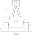
- Figures 1 and 2 illustrate mounting of an object 1 on a platform 2 in accordance with the principles of the present invention.
- the platform 2 is illustrated as a moveable wheeled vehicle 2, and the object is an image capture device, such as a camera 1.
- the object 1 and platform 2 are not limited to these examples, which are used for clarity of description below.
- the principles of the present invention are applicable to the support and stabilisation of any appropriate object, on any appropriate platform.
- the object and platform may be of any appropriate scale and size.
- the object may be supported by another stabilisation platform if required.
- the wheeled vehicle 2 has a plurality of ground engaging wheels 4 mounted on a chassis 5.
- the wheels 4 engage a ground surface 3 and, as is well known and understood, enable the vehicle 2 to move across the ground surface 3.
- a support and stabilisation system 6 is mounted on the chassis 5, and the camera 1 is mounted on the support 6. It will be appreciated that the support and stabilisation system 6 is illustrate schematically in Figure 1 and 2 for the sake of clarity of these drawings.
- the support and stabilisation system 6 enables the camera 1 to be supported above the chassis 5 of the vehicle 2, such that the size of the support and stabilisation system 6 is small or non-existent in images generated by the camera 2.
- a support and stabilisation system 6 embodying the principles of the present invention is mountable within the footprint of the vehicle 2 or another platform.
- the support and stabilisation system 6 extends above the chassis 5 sufficiently to enable the camera to capture images that do not include the chassis 5 or support and stabilisation system 6, or that contain a minimal view of those components.
- the support and stabilisation system 6 is designed to have a small footprint such that wide-angle image capture, such as 360° capture, does not result in the chassis 5 or support and stabilisation system 6 being seen significantly in the resulting images.
- the support and stabilisation system 6 is arranged to enable the camera 1 to be maintained in a desirable position relative to the ground surface 3, and to an initial reference position. Where the amount of translation and/or rotation of the vehicle 2 exceeds the amount of compensating movement available to the support and stabilisation system 6, then the system 6 serves to smooth out such movements, such that the positional changes of the camera 1 are typically slower than the positional changes of the vehicle 2.
- the camera 1 may be mounted on the support and stabilisation system 6 using a movable mount to allow the camera to be rotated (about one or more axes) with respect to the support and stabilisation system 6.
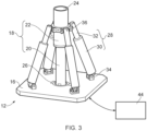
- FIG 3 illustrates a support and stabilisation system 10 embodying the present invention.
- the system 10 comprises a support and stabilisation system 12 and a control unit 14.
- the support and stabilisation system 12 will be referred to as the "support 12" in the following description.
- the control unit 14 is illustrated as being separate from the support 12, but it will be readily appreciated that the control unit may be located in any convenient position.
- the support 12 comprises a base 16 for attachment to a first object, for example the vehicle or other support object.
- the base 16 is preferably provided by a substantially planar base portion.
- the base 16 is preferably of a substantially rigid material.
- a telescopic element 18 is mounted on the base 16, and defines a longitudinal axis of the system 10.
- the telescopic element 18 has a first portion 20 rotatably engaged with the base 16, and a second portion 22 linearly slidably engaged with the first portion 20.
- the second portion 22 of the telescopic element 18 defines an attachment portion 24 adapted for reception of a second object, for example a camera or other device.
- the second object may be attached directly to the attachment portion, or may be attached via a secondary stabilisation platform or system.
- the first portion 20 of the telescopic element 18 is attached to the base 16 by a multi-axis gimbal 26.
- the multi-axis gimbal 26 is centred on the longitudinal axis, and enables the telescopic element 18 to rotate freely in any polar orientation with respect to the base 16, about the centre of the gimbal 26, so as to provide the telescopic element 16 with a range of angular movement with respect to the base 16.
- a neutral position as shown in Figure 3 , the telescopic element 18 extends substantially perpendicularly with respect to the substantially planar base 16.
- the support 12 further comprises a plurality of linear actuators 28; in the example of Figure 3 , four linear actuators 28 are shown. Preferably, at least three linear actuators 28 are provided.
- the linear actuators 28 may be electrical (for example driven by a motor or other electrical component), hydraulic, or pneumatic.
- Each linear actuator 28 has a first portion rotatably engaged with the base 16, and a second portion 32 linearly slidably engaged with the first portion 30 of the actuator 28 concerned.
- the second portion 32 of each linear actuator 28 is rotatably engaged with the second portion 22 of the telescopic element 18.
- the linear actuators 28 define respective longitudinal axes, and each linear actuator 18 is operable to drive the second portion 32 thereof linearly along its longitudinal axis with respect to the first portion 30 thereof. Accordingly, extension and retraction of the second portions 32 of the linear actuators 28 causes the second portion 22 of the telescopic element 18 to move linearly with respect to the first portion 20, and rotationally with respect to the base 16 in a controlled manner.
- the first portions 30 of the linear actuators 28 are attached to the base 16 by respective first two-axis pivoting joints 34.
- the second portions 32 of the linear actuators 28 are attached to the second portions 22 of the telescopic element 18 by respective second two-axis pivoting joints 36.
- the second portions 32 of the linear actuators 28 are shown extending from inside the first portions 30. It will be readily appreciated that the opposite configuration is also possible, with the second portions 32 extending around the first portions 30.
- the first portions 30 of the linear actuators 28 may be attached to the planar base 16, or may be attached to the base 16 via suitable mounting portions.
- Each of the first two-axis pivoting joints 34 allow the respective first portions 32 of the linear actuators 28 to rotate with respect to the base 16 about two axes.
- the first axis extends substantially parallel to the plane of the base 16, and the second axis extends substantially transversely to the longitudinal axis of the linear actuator 28 concerned.
- Each of the second two-axis pivoting joints 36 allow the respective second portions 32 of the linear actuators 28 to rotate with respect to the respective second portions 32 of the telescopic element 18 about two axes.
- the first axis extends substantially tangentially to the respective second portion 32 of the telescopic element 18, and the second axis extends substantially transversely to the longitudinal axis of the linear actuator 28 concerned.
- the linear actuators 28 may be electrically, hydraulically or pneumatically actuated, and are controlled by the control unit 14.
- the control unit 14 is connected to receive sensor information, and operates to use that sensor information to supply control signals to the linear actuators. This control of the linear actuators 28 adjusts the relative linear position of the second portions 32 with respect to the first portions 30 of the respective linear actuators, thereby controlling the linear and polar position of the telescopic element 18.
- Sensors are provided on or in the support and stabilisation system 6, and operate to provide the sensor information to the control unit.
- the sensors may be provided by any suitable combination of sensors.
- a six-axis inertial measurement unit IMU
- an IMU is an electronic device that measures and reports specific force, angular rate, and sometimes the magnetic field surrounding an object, using a combination of accelerometers and gyroscopes, sometimes also magnetometers.
- Other possible sensors include a linear position sensor for the telescopic element 18 and/or for each linear actuator 28, an angular position sensor for the telescopic element 18, a multi axis accelerometer, a gravity sensor for determining a vertical direction, and an altimeter.
- Additional sensors and feedback devices may be provided on the vehicle or other platform for supplying additional information to the control unit 14. Furthermore, the control unit 14 may make use of additional information, such as positional information derived from Global Positioning System (GPS) data (or similar), for control of the support and stabilisation system 6.
- GPS Global Positioning System
- the control unit 14 operates to maintain the telescopic element 14 in a desired position and orientation relative to a predetermined reference, within the range of movement provided by the support and stabilisation system 6. In this manner, the attachment portion can be maintained in a desired position and orientation with respect to the predetermined reference, thereby maintaining the camera 1 in a desired position and orientation.
- the predetermined reference may be internal to the vehicle 2 and support 12, or may be external to the system, such as the horizon.
- the system 6 serves to smooth out such movements, such that the positional changes of the camera 1 are typically slower than the positional changes of the vehicle 2.
- control unit 14 operates in real time in order to maintain the camera 1 in the desired position and orientation in real time.
- the system can then be described as "active" system.
- This predetermined reference may be set upon initial calibration of the support and stabilisation system 6. Following attachment of the camera 1 to the system 6, the user sets an initial position for the camera 1 and system 6, and calibrates the control system 14 in order to set the predetermined reference. For optimum performance, this initial calibration can also include mechanical balancing of the system 6.
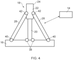
- Figure 4 shows a simplified side view of another support and stabilisation system embodying the present invention.
- the Figure 4 embodiment is a generalised version of the Figure 3 embodiment, and is of the same overall structure.
- the Figure 4 embodiment differs from the Figure 3 embodiment by virtue of the general nature of the mounting rotational mounting of the telescopic element 18 and the linear actuators 28.
- first bearing element 38 may be a multi axis pivot, such as a gimbal as in Figure 3 , a two-pivot joint, a ball joint, a flexible resilient member, or any other appropriate bearing element that allows the first portion 20 of the telescopic element 18 to rotate with respect to the base 16.
- Different first bearing elements 38 allow for different respective axes of rotation of the telescopic element.
- a two-axis gimbal allows for rotation about two axes, each of which is substantially perpendicular to the longitudinal axis of the telescopic element 18.
- a ball joint would allow this two-axis rotation, and also allow for rotation of the telescopic element 18 about the longitudinal axis thereof.
- respective second bearing elements 40 attach the linear actuators 28 to the base 16, and respective third bearing elements 42 attach the linear actuators 28 to the second portion 22 of the telescopic element 18.
- the second and third bearing elements 40 and 42 may be of the same type, or may be of different types.
- the second and third bearing elements 40 and 42 may be provided by any suitable rotational element, such as a multi-axis pivot, such as a gimbal, a two-pivot joint, a ball joint, a flexible resilient member, or any other appropriate bearing element that allows the linear actuator 28 to rotate with respect to the base 16 and second portion 22 of the telescopic element 18.
- Figure 4 the second portion 22 of the telescopic element 18 extends outside of first portion thereof.
- Figure 5 illustrates the opposite situation in which the second portion 22 of the telescopic element 18 extends within the first portion 20 thereof.
- the remaining configuration and operation of the example of Figure 5 is substantially the same as that for Figure 4 , with the same reference numerals used in each of Figures 4 and 5 .
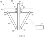
- Figure 6 illustrates, in partial cross-sectional simplified schematic side view, another support and stabilisation system embodying the present invention.
- the system of Figure 6 Is similar in overall concept to the embodiments shown in, and described with reference to, the previous Figures.
- the linear actuators extend to a side of the base opposite to that of the attachment portion for the object being supported.
- a support 50 comprises a base 52 for attachment to the platform.
- a telescopic element 54 extends through the base 52, through an aperture 62 defined in the base 52.
- the telescopic element 54 comprises a first portion 56, arranged for rotational engagement with the base 52, and a second portion 58 which extends through the first portion 56, and through the aperture 62 in the base 52.
- the second portion 58 of the telescopic element 54 is arranged for linear movement with respect to the first portion 56.
- the second portion of the telescopic element 54 provides an attachment portion 60 for the attachment of the object to the support 50.
- the first portion 56 of the telescopic element 54 is mounted on the base 52 by way of a first bearing element 64.
- the first bearing element 64 may be a multi axis pivot, such as a gimbal, a two-pivot joint, a ball joint, a flexible resilient member, or any other appropriate bearing element that allows the first portion 56 of the telescopic element 54 to rotate with respect to the base 52.
- Different first bearing elements 64 allow for different respective axes of rotation of the telescopic element.
- a two-axis gimbal allows for rotation about two axes, each of which is substantially perpendicular to the longitudinal axis of the telescopic element 54.
- a ball joint would allow this two-axis rotation, and also allow for rotation of the telescopic element 54 about the longitudinal axis thereof.
- a plurality of linear actuators 66 are attached between the base 52 and the second portion 58 of the telescopic element 54.
- Respective second bearing elements 68 attach the linear actuators 66 to the base 52
- respective third bearing elements 70 attach the linear actuators 66 to the second portion 58 of the telescopic element 54.
- the second and third bearing elements 68 and 70 may be of the same type, or may be of different types.
- the second and third bearing elements 68 and 70 may be provided by any suitable rotational element, such as a multi-axis pivot, such as a gimbal, a two-pivot joint, a ball joint, a flexible resilient member, or any other appropriate bearing element that allows the linear actuator 66 to rotate with respect to the base 52 and second portion 58 of the telescopic element 54.
- a multi-axis pivot such as a gimbal, a two-pivot joint, a ball joint, a flexible resilient member, or any other appropriate bearing element that allows the linear actuator 66 to rotate with respect to the base 52 and second portion 58 of the telescopic element 54.
- a control unit 72 is provided, and operates as the control unit described above.
- a support and stabilisation system embodying the present invention would be mounting a camera 1 to the roof of a vehicle 2.
- the vehicle 2 can then drive over bumpy and angled terrain and the support and stabilisation system is able to control the position the camera 1 such that, for example, the camera remains substantially level with respect to the horizon.
- the system is able to control the position of the camera so as to remove or reduce any sudden vertical displacements or rotations that might create undesirable output from the camera 1.
- the stabiliser system is able to reduce displacement as a result of the vehicle pitching or rolling.
- Figures 1 and 2 illustrate a wheeled vehicle 2, it is to be understood that the principles of the present invention apply to any type of support vehicle or object.
- vehicles include wheeled vehicles, tracked vehicles, airborne and water borne vehicles.
- the support 12 may be attached directly to a vehicle, or may be attached to any other piece of equipment.
- a system embodying the principles of the present invention may be used to attach any first object to any second object.
- the description above relates to image capturing devices, such as cameras, but it will be readily appreciated that other devices may benefit from enhanced stability.
- a support and stabilisation system embodying the principles of the present invention may be used to provide a satellite antenna with a stabilised support.
- Other objects and systems requiring stabilised support may also benefit from a support and stabilisation system embodying the principles of the present invention.
Landscapes
- Engineering & Computer Science (AREA)
- General Engineering & Computer Science (AREA)
- Mechanical Engineering (AREA)
- Aviation & Aerospace Engineering (AREA)
- Physics & Mathematics (AREA)
- General Physics & Mathematics (AREA)
- Chemical & Material Sciences (AREA)
- Combustion & Propulsion (AREA)
- Ocean & Marine Engineering (AREA)
- Accessories Of Cameras (AREA)
- Studio Devices (AREA)
Description
- The present invention relates to support and stabilisation systems.
- It is often desirable to mount an object, such as a camera, onto a support platform. In the case when the platform is stationary, such mounting presents no particular issues.
- However, when the support platform is movable, such as a on a vehicle, there are significant issues to be overcome in order to maintain the object in a stable condition. In the example of a camera, it is desirable to maintain the camera stable for providing images of a suitable quality. In particular, there are significant challenges presented by mounting a camera on a vehicle that traverses rough ground, on a water-borne vehicle, due to the ever-changing nature of the surface on which the vehicle and camera are supported. Similar issues occur with airborne vehicles, and affect mounting of other objects, such as sensor devices, or projection apparatus. In order to compensate for movement of the vehicle, systems have been proposed that make use of a complex arrangement of multi-axis gimbals and powered actuators.
- However, such previous-considered designs have several drawbacks. Firstly, the support structures are cumbersome and heavy, which restricts the possible applications for the resulting system. Secondly, previously-considered designs are not able to maintain an object position with respect to an initial reference position. For example, previously-considered designs are not able to maintain the camera in a substantially fixed, or smoothly changing, vertical position with respect to the horizon in real time. Thirdly, previously considered designs are not suitable for wide angle image capture, since the structure of the support restricts the angle of view.
-
US 2011/163222 A1 discloses a tracking device for automatically following a moving light source that is detectable in the presence of ambient light.US 2012/026467 A1 discloses a camera crane mobile base has a drive motor assembly at each corner of a chassis. - It is, therefore, desirable to provide a support and stabilisation system that seeks to address the issues of the previously-considered designs.
- According to an aspect of the present invention, there is provided a support and stabilisation system as claimed in claim 1.
- In one example, the first portion of the telescopic element is rotatably engaged with the base by a first rotational bearing element.
- In one example, the first portion of each linear actuator is rotatably engaged with the base by a second rotational bearing element.
- In one example, the second portion of each linear actuator is rotatably engaged with the second portion of the telescopic element by a third rotational bearing element.
- In one example, the first bearing element is chosen from a group including multi-axis pivot, a gimbal, a two-pivot joint, a ball joint, and a flexible resilient member.
- In one example, the second bearing element is chosen from a group including multi-axis pivot, a gimbal, a two-pivot joint, a ball joint, and a flexible resilient member.
- In one example, the third bearing element is chosen from a group including multi-axis pivot, a gimbal, a two-pivot joint, a ball joint, and a flexible resilient member.
- In one example, the base is provided by a substantially planar base portion.
- In one example, the telescopic element defines a longitudinal axis of the system, and the linear actuators define respective actuator longitudinal axes, which are arranged to extend from the base towards the longitudinal axis of the system.
- In one example, the linear actuators are engaged with the second portion of the telescopic element at substantially the same axial position on that second portion.
- One example system comprises three such linear actuators.
- One example system comprises four such linear actuators.
- In one example, the control unit is operable to control the linear actuators so as to maintain the linear and angular position of the attachment element with respect to a predetermined reference.
- In one example, the predetermined reference is a horizon.
- In one example, the control unit is operable to maintain the attachment element at a predetermined height with respect to the predetermined reference.
- In one example, the first object is a vehicle. The vehicle may be one of a wheeled vehicle, a tracked vehicle, and a water-borne vehicle.
- In one example, the second object is a camera device, an image recording device, or a video or film camera device.
-
-
Figures 1 and2 are schematic side and end illustrations respectively of an object mounted on a platform; -
Figure 3 is a schematic illustration of a support and stabilisation system embodying the present invention; -
Figure 4 is a simplified schematic side view of another support and stabilisation system embodying the present invention; -
Figure 5 is a simplified schematic side view of another support and stabilisation system embodying the present invention; and -
Figure 6 is a simplified schematic partially cross-sectional side view of another support and stabilisation system embodying the present invention. -
Figures 1 and2 illustrate mounting of an object 1 on aplatform 2 in accordance with the principles of the present invention. In the example ofFigures 1 and2 , theplatform 2 is illustrated as a moveablewheeled vehicle 2, and the object is an image capture device, such as a camera 1. It will be readily appreciated that the object 1 andplatform 2 are not limited to these examples, which are used for clarity of description below. The principles of the present invention are applicable to the support and stabilisation of any appropriate object, on any appropriate platform. The object and platform may be of any appropriate scale and size. The object may be supported by another stabilisation platform if required. - In the example of
Figures 1 and2 , thewheeled vehicle 2 has a plurality of ground engaging wheels 4 mounted on a chassis 5. The wheels 4 engage aground surface 3 and, as is well known and understood, enable thevehicle 2 to move across theground surface 3. A support and stabilisation system 6 is mounted on the chassis 5, and the camera 1 is mounted on the support 6. It will be appreciated that the support and stabilisation system 6 is illustrate schematically inFigure 1 and2 for the sake of clarity of these drawings. - The support and stabilisation system 6 enables the camera 1 to be supported above the chassis 5 of the
vehicle 2, such that the size of the support and stabilisation system 6 is small or non-existent in images generated by thecamera 2. In particular, a support and stabilisation system 6 embodying the principles of the present invention is mountable within the footprint of thevehicle 2 or another platform. As will be described in more detail below, the support and stabilisation system 6 extends above the chassis 5 sufficiently to enable the camera to capture images that do not include the chassis 5 or support and stabilisation system 6, or that contain a minimal view of those components. In addition, the support and stabilisation system 6 is designed to have a small footprint such that wide-angle image capture, such as 360° capture, does not result in the chassis 5 or support and stabilisation system 6 being seen significantly in the resulting images. - As the
vehicle 2 moves across theground surface 3, the chassis 5 experiences vertical translation T (i.e. translation substantially perpendicular to the ground surface 3), and rotation about a plurality of axes. Two such axes are illustrated by arrows R1 and R2 in the Figures. The support and stabilisation system 6 is arranged to enable the camera 1 to be maintained in a desirable position relative to theground surface 3, and to an initial reference position. Where the amount of translation and/or rotation of thevehicle 2 exceeds the amount of compensating movement available to the support and stabilisation system 6, then the system 6 serves to smooth out such movements, such that the positional changes of the camera 1 are typically slower than the positional changes of thevehicle 2. - The camera 1 may be mounted on the support and stabilisation system 6 using a movable mount to allow the camera to be rotated (about one or more axes) with respect to the support and stabilisation system 6.
-
Figure 3 illustrates a support and stabilisation system 10 embodying the present invention. The system 10 comprises a support andstabilisation system 12 and acontrol unit 14. The support andstabilisation system 12 will be referred to as the "support 12" in the following description. Thecontrol unit 14 is illustrated as being separate from thesupport 12, but it will be readily appreciated that the control unit may be located in any convenient position. - The
support 12 comprises abase 16 for attachment to a first object, for example the vehicle or other support object. Thebase 16 is preferably provided by a substantially planar base portion. Thebase 16 is preferably of a substantially rigid material. Atelescopic element 18 is mounted on thebase 16, and defines a longitudinal axis of the system 10. Thetelescopic element 18 has afirst portion 20 rotatably engaged with thebase 16, and asecond portion 22 linearly slidably engaged with thefirst portion 20. Thesecond portion 22 of thetelescopic element 18 defines anattachment portion 24 adapted for reception of a second object, for example a camera or other device. The second object may be attached directly to the attachment portion, or may be attached via a secondary stabilisation platform or system. - In one example, the
first portion 20 of thetelescopic element 18 is attached to thebase 16 by amulti-axis gimbal 26. Themulti-axis gimbal 26 is centred on the longitudinal axis, and enables thetelescopic element 18 to rotate freely in any polar orientation with respect to thebase 16, about the centre of thegimbal 26, so as to provide thetelescopic element 16 with a range of angular movement with respect to thebase 16. In a neutral position, as shown inFigure 3 , thetelescopic element 18 extends substantially perpendicularly with respect to the substantiallyplanar base 16. - The
support 12 further comprises a plurality oflinear actuators 28; in the example ofFigure 3 , fourlinear actuators 28 are shown. Preferably, at least threelinear actuators 28 are provided. Thelinear actuators 28 may be electrical (for example driven by a motor or other electrical component), hydraulic, or pneumatic. - Each
linear actuator 28 has a first portion rotatably engaged with thebase 16, and asecond portion 32 linearly slidably engaged with thefirst portion 30 of theactuator 28 concerned. Thesecond portion 32 of eachlinear actuator 28 is rotatably engaged with thesecond portion 22 of thetelescopic element 18. Thelinear actuators 28 define respective longitudinal axes, and eachlinear actuator 18 is operable to drive thesecond portion 32 thereof linearly along its longitudinal axis with respect to thefirst portion 30 thereof. Accordingly, extension and retraction of thesecond portions 32 of thelinear actuators 28 causes thesecond portion 22 of thetelescopic element 18 to move linearly with respect to thefirst portion 20, and rotationally with respect to the base 16 in a controlled manner. - The
first portions 30 of thelinear actuators 28 are attached to thebase 16 by respective first two-axis pivoting joints 34. Thesecond portions 32 of thelinear actuators 28 are attached to thesecond portions 22 of thetelescopic element 18 by respective second two-axis pivoting joints 36. In the example ofFigure 3 , thesecond portions 32 of thelinear actuators 28 are shown extending from inside thefirst portions 30. It will be readily appreciated that the opposite configuration is also possible, with thesecond portions 32 extending around thefirst portions 30. Thefirst portions 30 of thelinear actuators 28 may be attached to theplanar base 16, or may be attached to thebase 16 via suitable mounting portions. - Each of the first two-axis pivoting joints 34 allow the respective
first portions 32 of thelinear actuators 28 to rotate with respect to the base 16 about two axes. The first axis extends substantially parallel to the plane of thebase 16, and the second axis extends substantially transversely to the longitudinal axis of thelinear actuator 28 concerned. - Each of the second two-axis pivoting joints 36 allow the respective
second portions 32 of thelinear actuators 28 to rotate with respect to the respectivesecond portions 32 of thetelescopic element 18 about two axes. The first axis extends substantially tangentially to the respectivesecond portion 32 of thetelescopic element 18, and the second axis extends substantially transversely to the longitudinal axis of thelinear actuator 28 concerned. - The
linear actuators 28 may be electrically, hydraulically or pneumatically actuated, and are controlled by thecontrol unit 14. Thecontrol unit 14 is connected to receive sensor information, and operates to use that sensor information to supply control signals to the linear actuators. This control of thelinear actuators 28 adjusts the relative linear position of thesecond portions 32 with respect to thefirst portions 30 of the respective linear actuators, thereby controlling the linear and polar position of thetelescopic element 18. - Sensors are provided on or in the support and stabilisation system 6, and operate to provide the sensor information to the control unit. The sensors may be provided by any suitable combination of sensors. For example, a six-axis inertial measurement unit (IMU) may be provided. As is well known and understood, an IMU is an electronic device that measures and reports specific force, angular rate, and sometimes the magnetic field surrounding an object, using a combination of accelerometers and gyroscopes, sometimes also magnetometers. Other possible sensors include a linear position sensor for the
telescopic element 18 and/or for eachlinear actuator 28, an angular position sensor for thetelescopic element 18, a multi axis accelerometer, a gravity sensor for determining a vertical direction, and an altimeter. Additional sensors and feedback devices may be provided on the vehicle or other platform for supplying additional information to thecontrol unit 14. Furthermore, thecontrol unit 14 may make use of additional information, such as positional information derived from Global Positioning System (GPS) data (or similar), for control of the support and stabilisation system 6. - The
control unit 14 operates to maintain thetelescopic element 14 in a desired position and orientation relative to a predetermined reference, within the range of movement provided by the support and stabilisation system 6. In this manner, the attachment portion can be maintained in a desired position and orientation with respect to the predetermined reference, thereby maintaining the camera 1 in a desired position and orientation. The predetermined reference may be internal to thevehicle 2 andsupport 12, or may be external to the system, such as the horizon. - Where the amount of translation and/or rotation of the
vehicle 2 exceeds the amount of compensating movement available to the support and stabilisation system 6, then the system 6 serves to smooth out such movements, such that the positional changes of the camera 1 are typically slower than the positional changes of thevehicle 2. - Preferably, the
control unit 14 operates in real time in order to maintain the camera 1 in the desired position and orientation in real time. The system can then be described as "active" system. - This predetermined reference may be set upon initial calibration of the support and stabilisation system 6. Following attachment of the camera 1 to the system 6, the user sets an initial position for the camera 1 and system 6, and calibrates the
control system 14 in order to set the predetermined reference. For optimum performance, this initial calibration can also include mechanical balancing of the system 6. -
Figure 4 shows a simplified side view of another support and stabilisation system embodying the present invention. TheFigure 4 embodiment is a generalised version of theFigure 3 embodiment, and is of the same overall structure. TheFigure 4 embodiment differs from theFigure 3 embodiment by virtue of the general nature of the mounting rotational mounting of thetelescopic element 18 and thelinear actuators 28. - In
Figure 4 , thefirst portion 20 of thetelescopic element 18 is mounted on thebase 16 by way of afirst bearing element 38. Thefirst bearing element 38 may be a multi axis pivot, such as a gimbal as inFigure 3 , a two-pivot joint, a ball joint, a flexible resilient member, or any other appropriate bearing element that allows thefirst portion 20 of thetelescopic element 18 to rotate with respect to thebase 16. Differentfirst bearing elements 38 allow for different respective axes of rotation of the telescopic element. For example, a two-axis gimbal allows for rotation about two axes, each of which is substantially perpendicular to the longitudinal axis of thetelescopic element 18. A ball joint would allow this two-axis rotation, and also allow for rotation of thetelescopic element 18 about the longitudinal axis thereof. - Also illustrated in
Figure 4 , respectivesecond bearing elements 40 attach thelinear actuators 28 to thebase 16, and respectivethird bearing elements 42 attach thelinear actuators 28 to thesecond portion 22 of thetelescopic element 18. The second andthird bearing elements third bearing elements linear actuator 28 to rotate with respect to thebase 16 andsecond portion 22 of thetelescopic element 18. - In
Figure 4 , thesecond portion 22 of thetelescopic element 18 extends outside of first portion thereof.Figure 5 illustrates the opposite situation in which thesecond portion 22 of thetelescopic element 18 extends within thefirst portion 20 thereof. The remaining configuration and operation of the example ofFigure 5 is substantially the same as that forFigure 4 , with the same reference numerals used in each ofFigures 4 and5 . -
Figure 6 illustrates, in partial cross-sectional simplified schematic side view, another support and stabilisation system embodying the present invention. The system ofFigure 6 Is similar in overall concept to the embodiments shown in, and described with reference to, the previous Figures. In the example ofFigure 6 , the linear actuators extend to a side of the base opposite to that of the attachment portion for the object being supported. - In
Figure 6 , asupport 50 comprises abase 52 for attachment to the platform. Atelescopic element 54 extends through thebase 52, through anaperture 62 defined in thebase 52. Thetelescopic element 54 comprises afirst portion 56, arranged for rotational engagement with thebase 52, and asecond portion 58 which extends through thefirst portion 56, and through theaperture 62 in thebase 52. Thesecond portion 58 of thetelescopic element 54 is arranged for linear movement with respect to thefirst portion 56. The second portion of thetelescopic element 54 provides anattachment portion 60 for the attachment of the object to thesupport 50. - The
first portion 56 of thetelescopic element 54 is mounted on thebase 52 by way of afirst bearing element 64. Thefirst bearing element 64 may be a multi axis pivot, such as a gimbal, a two-pivot joint, a ball joint, a flexible resilient member, or any other appropriate bearing element that allows thefirst portion 56 of thetelescopic element 54 to rotate with respect to thebase 52. Differentfirst bearing elements 64 allow for different respective axes of rotation of the telescopic element. For example, a two-axis gimbal allows for rotation about two axes, each of which is substantially perpendicular to the longitudinal axis of thetelescopic element 54. A ball joint would allow this two-axis rotation, and also allow for rotation of thetelescopic element 54 about the longitudinal axis thereof. - A plurality of
linear actuators 66 are attached between the base 52 and thesecond portion 58 of thetelescopic element 54. Respectivesecond bearing elements 68 attach thelinear actuators 66 to thebase 52, and respectivethird bearing elements 70 attach thelinear actuators 66 to thesecond portion 58 of thetelescopic element 54. The second andthird bearing elements third bearing elements linear actuator 66 to rotate with respect to thebase 52 andsecond portion 58 of thetelescopic element 54. - A
control unit 72 is provided, and operates as the control unit described above. - The example system of
Figure 6 allows the object being supported to be closer to the base of the support system, whilst retaining the advantages of an embodiment of the present invention. - One particular example of the use of a support and stabilisation system embodying the present invention would be mounting a camera 1 to the roof of a
vehicle 2. Thevehicle 2 can then drive over bumpy and angled terrain and the support and stabilisation system is able to control the position the camera 1 such that, for example, the camera remains substantially level with respect to the horizon. The system is able to control the position of the camera so as to remove or reduce any sudden vertical displacements or rotations that might create undesirable output from the camera 1. - If the
base 16 is located at the centre of thevehicle 2, the stabiliser system is able to reduce displacement as a result of the vehicle pitching or rolling. - Although
Figures 1 and2 illustrate awheeled vehicle 2, it is to be understood that the principles of the present invention apply to any type of support vehicle or object. Examples of vehicles include wheeled vehicles, tracked vehicles, airborne and water borne vehicles. Thesupport 12 may be attached directly to a vehicle, or may be attached to any other piece of equipment. It will also be readily appreciated that a system embodying the principles of the present invention may be used to attach any first object to any second object. The description above relates to image capturing devices, such as cameras, but it will be readily appreciated that other devices may benefit from enhanced stability. For example, a support and stabilisation system embodying the principles of the present invention may be used to provide a satellite antenna with a stabilised support. Other objects and systems requiring stabilised support may also benefit from a support and stabilisation system embodying the principles of the present invention.
Claims (15)
- An active stabilisation system (12) for mounting an object to a movable platform, the stabilisation system comprising:a base (16) for attachment to a moveable platform (2);a telescopic element (18) having a first portion (20) rotatably engaged with the base (16), and a second portion (22) linearly slidably engaged with the first portion (20) and having an attachment portion (24) adapted for reception of an object (1);a plurality of linear actuators (28), each linear actuator (28) having a first portion (30) rotatably engaged with the base (16), and a second portion (32) linearly slidably engaged with the first portion (30) of the actuator concerned, and rotatably engaged with the second portion (22) of the telescopic element, the plurality of linear actuators (28) being operable to drive the second portion (22) of the telescopic element linearly with respect to the first portion of the telescopic element (20) and rotationally with respect to the base (16);a plurality of sensors on or in the stabilisation system, and operable to provide sensor data relating to a position of the attachment portion; anda control unit (14) operable to receive the sensor data and to supply real time control signals to the linear actuators (28) in response to reception of the sensor data, thereby to control the relative linear positions of the second portions (32) of the linear actuators with respect to the first portions (30) of the respective linear actuators.
- A stabilisation system (12) as claimed in claim 1, wherein the first portion (20) of the telescopic element (18) is rotatably engaged with the base by a first rotational bearing element (26).
- A stabilisation system (12) as claimed in claim 1 or 2, wherein the first portion (20) of each linear actuator (28) is rotatably engaged with the base (16) by a second rotational bearing element (26).
- A stabilisation system (12) as claimed in claim 1, 2 or 3, wherein the second portion (32) of each linear actuator is rotatably engaged with the second portion (22) of the telescopic element (18) by a third rotational bearing element (36).
- A stabilisation system (12) as claimed in any one of claims 2, 3 and 4, wherein one or more of:
the first bearing element (26) and/or the second bearing element (34) and/or the third bearing element (36) is chosen from a group including multi-axis pivot, a gimbal, a two-pivot joint, a ball joint, and a flexible resilient member. - A stabilisation system (12) as claimed in any one of the preceding claims, wherein the telescopic element (18) defines a longitudinal axis of the system, and the linear actuators (28) define respective actuator longitudinal axes, which are arranged to extend from the base (16) towards the longitudinal axis of the system (12).
- A stabilisation system (12) as claimed in any one of the preceding claims, wherein the linear actuators (28) are engaged with the second portion (22) of the telescopic element at substantially the same axial position on that second portion (22).
- A stabilisation system (12) as claimed in any one of the preceding claims, comprising three or more such linear actuators (28).
- A stabilisation system (12) as claimed in any one of the preceding claims, wherein the control unit (14) is operable to control the linear actuators (28) so as to maintain the linear and angular position of the attachment portion (24) with respect to a predetermined reference.
- A stabilisation system (12) as claim in any one of the preceding claims, wherein the control unit (16) is operable to maintain the attachment portion (24) at a predetermined height with respect to a predetermined reference.
- A stabilisation system (12) as claimed in any one of the preceding claims, wherein the control unit (16) is operable to control the linear actuators (28) so as to smooth movement of the attachment portion (24) with respect to the base (16).
- A stabilisation system (12) as claimed in any one of the preceding claims, wherein the platform (2) is a vehicle.
- A stabilisation system (12) as claimed in claim 12, wherein the vehicle is one of a wheeled vehicle, a tracked vehicle, an airborne vehicle, and a water-borne vehicle.
- A stabilisation system as claimed in any one of the preceding claims, wherein the object is a camera device, an image recording device, or a video or film camera device.
- A stabilisation system as claimed in any one of claims 1-14, wherein the object is chosen from a group including a sensor device, a projection device, a light source device, an antenna, a directional antenna.
Applications Claiming Priority (2)
| Application Number | Priority Date | Filing Date | Title |
|---|---|---|---|
| GB1718935.8A GB2568481B (en) | 2017-11-16 | 2017-11-16 | Support and stabilisation systems |
| PCT/GB2018/053276 WO2019097218A1 (en) | 2017-11-16 | 2018-11-13 | Support and stabilisation systems |
Publications (3)
| Publication Number | Publication Date |
|---|---|
| EP3710740A1 EP3710740A1 (en) | 2020-09-23 |
| EP3710740B1 true EP3710740B1 (en) | 2024-09-11 |
| EP3710740C0 EP3710740C0 (en) | 2024-09-11 |
Family
ID=60805438
Family Applications (1)
| Application Number | Title | Priority Date | Filing Date |
|---|---|---|---|
| EP18804106.5A Active EP3710740B1 (en) | 2017-11-16 | 2018-11-13 | Support and stabilisation systems |
Country Status (5)
| Country | Link |
|---|---|
| US (1) | US11209118B2 (en) |
| EP (1) | EP3710740B1 (en) |
| CA (1) | CA3082042A1 (en) |
| GB (1) | GB2568481B (en) |
| WO (1) | WO2019097218A1 (en) |
Families Citing this family (15)
| Publication number | Priority date | Publication date | Assignee | Title |
|---|---|---|---|---|
| CN110645452A (en) * | 2019-09-17 | 2020-01-03 | 厦门大学 | A stable and reliable folding photographic stand |
| US11258159B2 (en) * | 2020-03-19 | 2022-02-22 | United States Of America, As Represented By The Secretary Of The Navy | Antenna pedestal |
| DE102020109341B3 (en) | 2020-04-03 | 2021-07-01 | FoMa Systems GmbH | Stabilization device and method for stabilizing a fastening component |
| EP4186050A1 (en) * | 2020-08-28 | 2023-05-31 | Siemens Industry Software NV | Critical scenario identification for verification and validation of vehicles |
| DE102021200760A1 (en) | 2021-01-28 | 2022-07-28 | Zf Friedrichshafen Ag | Mounting device for an environment detection sensor of a road vehicle that can be operated automatically, control unit for such a mounting device and computer-implemented method for regulating and/or controlling such a mounting device |
| CN113090907A (en) * | 2021-04-27 | 2021-07-09 | 马鞍山德友机械制造有限公司 | Hydraulic equipment convenient to install and use method thereof |
| CN113483225A (en) * | 2021-07-20 | 2021-10-08 | 江苏亨通光电股份有限公司 | Automatic horizontal adjusting device and tripod |
| CN113588011A (en) * | 2021-09-01 | 2021-11-02 | 青岛科技大学 | Measuring device |
| CN113715335A (en) * | 2021-09-01 | 2021-11-30 | 青岛科技大学 | Movement device and operating device |
| DE102021211978A1 (en) | 2021-10-25 | 2023-04-27 | Continental Automotive Technologies GmbH | SYSTEM AND METHOD FOR STABILIZING ONE OR MORE SENSORS ON A VEHICLE |
| JP2023036655A (en) * | 2021-12-09 | 2023-03-14 | 阿波▲羅▼智▲聯▼(北京)科技有限公司 | vehicle chassis and vehicle |
| DE102022202493A1 (en) | 2022-03-14 | 2023-09-14 | Robert Bosch Gesellschaft mit beschränkter Haftung | Sensor device in a vehicle |
| CN117885651B (en) * | 2023-03-17 | 2025-02-07 | 李汝 | A multifunctional space planning terrain exploration and surveying vehicle |
| US20250028231A1 (en) * | 2023-07-21 | 2025-01-23 | Atmata LLC | Robotic camera movement filming solution |
| CN119078679B (en) * | 2024-08-28 | 2025-05-30 | 青岛中盛华正智能系统有限公司 | Anti-fall high-stability patrol intelligent robot |
Family Cites Families (8)
| Publication number | Priority date | Publication date | Assignee | Title |
|---|---|---|---|---|
| DE2105241A1 (en) * | 1971-02-04 | 1972-08-17 | Meinunger H | Tripod for photographic purposes |
| US8614742B2 (en) * | 2007-06-06 | 2013-12-24 | Palo Alto Research Center Incorporated | Miniature low cost pan/tilt magnetic actuation for portable and stationary video cameras |
| US8350204B2 (en) * | 2007-12-12 | 2013-01-08 | Mark Moser | Light source tracker |
| US9163774B2 (en) * | 2009-02-09 | 2015-10-20 | Evgeny M. Orlov | Support structure with features for precision leveling |
| US8550632B2 (en) * | 2010-07-29 | 2013-10-08 | Chapman/Leonard Studio Equipment, Inc. | Camera crane mobile base |
| US9622021B2 (en) * | 2014-07-06 | 2017-04-11 | Dynamount, Llc | Systems and methods for a robotic mount |
| CN106125770B (en) * | 2016-07-22 | 2019-06-07 | 西安电子科技大学 | A kind of two axle bed frame of orientation-pitching movement |
| IL251922A0 (en) * | 2017-04-25 | 2017-07-31 | Duke Airborne Systems Ltd | Stabilization system |
-
2017
- 2017-11-16 GB GB1718935.8A patent/GB2568481B/en not_active Expired - Fee Related
-
2018
- 2018-11-13 CA CA3082042A patent/CA3082042A1/en active Pending
- 2018-11-13 US US16/756,870 patent/US11209118B2/en active Active
- 2018-11-13 WO PCT/GB2018/053276 patent/WO2019097218A1/en not_active Ceased
- 2018-11-13 EP EP18804106.5A patent/EP3710740B1/en active Active
Also Published As
| Publication number | Publication date |
|---|---|
| GB201718935D0 (en) | 2018-01-03 |
| GB2568481B (en) | 2021-09-15 |
| GB2568481A (en) | 2019-05-22 |
| WO2019097218A1 (en) | 2019-05-23 |
| US20210190258A1 (en) | 2021-06-24 |
| CA3082042A1 (en) | 2019-05-23 |
| EP3710740A1 (en) | 2020-09-23 |
| US11209118B2 (en) | 2021-12-28 |
| EP3710740C0 (en) | 2024-09-11 |
Similar Documents
| Publication | Publication Date | Title |
|---|---|---|
| EP3710740B1 (en) | Support and stabilisation systems | |
| US9789976B2 (en) | Carrier having non-orthogonal axes | |
| US8847845B2 (en) | Holder for a movable sensor | |
| US9574703B2 (en) | Hand-held or vehicle mounted camera stabilization system | |
| CN108780316B (en) | Method and system for movement control of a flying device | |
| US7101045B2 (en) | Automatic pan and tilt compensation system for a camera support structure | |
| EP2984519B1 (en) | Apparatus and methods for stabilization and vibration reduction | |
| CN103939718B (en) | Increase steady The Cloud Terrace and control method thereof and the unmanned vehicle that carries the steady The Cloud Terrace of described increasing | |
| US10189580B2 (en) | Image stabilization and pointing control mechanization for aircraft imaging systems | |
| US9482530B2 (en) | Nadir/zenith inertial pointing assistance for two-axis gimbals | |
| US20200053290A1 (en) | Stabilized gimbal system with unlimited field of regard | |
| WO2017206421A1 (en) | Pan-tilt, imaging device and unmanned aerial vehicle | |
| US11137106B2 (en) | Stabilization system | |
| CN110546587B (en) | Method and apparatus for stabilizing a payload | |
| US20130321656A1 (en) | Wireless network connected camera positioning system | |
| WO2018128670A1 (en) | 360 degree camera mount for drones and robots | |
| JP2019182108A (en) | Unmanned flight body, unmanned flight method and unmanned flight program | |
| US11898690B1 (en) | Spherical field of view (FOV) multiple payloads gimbal system and method of manufacturing and using the same | |
| US6122102A (en) | Sighting apparatus for aiming an optical device | |
| KR20190143172A (en) | Pan-tilt-gimbal integrated system and control method thereof | |
| JP2007033401A (en) | Antenna control device for satellite tracking | |
| CN112373736A (en) | Satellite device for omnidirectional observation | |
| WO2026025380A1 (en) | Gimbal control method, gimbal, electronic device, and computer-readable storage medium | |
| CN111052020A (en) | Navigation apparatus |
Legal Events
| Date | Code | Title | Description |
|---|---|---|---|
| STAA | Information on the status of an ep patent application or granted ep patent |
Free format text: STATUS: UNKNOWN |
|
| STAA | Information on the status of an ep patent application or granted ep patent |
Free format text: STATUS: THE INTERNATIONAL PUBLICATION HAS BEEN MADE |
|
| PUAI | Public reference made under article 153(3) epc to a published international application that has entered the european phase |
Free format text: ORIGINAL CODE: 0009012 |
|
| STAA | Information on the status of an ep patent application or granted ep patent |
Free format text: STATUS: REQUEST FOR EXAMINATION WAS MADE |
|
| 17P | Request for examination filed |
Effective date: 20200615 |
|
| AK | Designated contracting states |
Kind code of ref document: A1 Designated state(s): AL AT BE BG CH CY CZ DE DK EE ES FI FR GB GR HR HU IE IS IT LI LT LU LV MC MK MT NL NO PL PT RO RS SE SI SK SM TR |
|
| AX | Request for extension of the european patent |
Extension state: BA ME |
|
| DAV | Request for validation of the european patent (deleted) | ||
| DAX | Request for extension of the european patent (deleted) | ||
| STAA | Information on the status of an ep patent application or granted ep patent |
Free format text: STATUS: EXAMINATION IS IN PROGRESS |
|
| 17Q | First examination report despatched |
Effective date: 20210728 |
|
| GRAP | Despatch of communication of intention to grant a patent |
Free format text: ORIGINAL CODE: EPIDOSNIGR1 |
|
| STAA | Information on the status of an ep patent application or granted ep patent |
Free format text: STATUS: GRANT OF PATENT IS INTENDED |
|
| INTG | Intention to grant announced |
Effective date: 20240408 |
|
| GRAS | Grant fee paid |
Free format text: ORIGINAL CODE: EPIDOSNIGR3 |
|
| GRAA | (expected) grant |
Free format text: ORIGINAL CODE: 0009210 |
|
| STAA | Information on the status of an ep patent application or granted ep patent |
Free format text: STATUS: THE PATENT HAS BEEN GRANTED |
|
| AK | Designated contracting states |
Kind code of ref document: B1 Designated state(s): AL AT BE BG CH CY CZ DE DK EE ES FI FR GB GR HR HU IE IS IT LI LT LU LV MC MK MT NL NO PL PT RO RS SE SI SK SM TR |
|
| REG | Reference to a national code |
Ref country code: GB Ref legal event code: FG4D |
|
| REG | Reference to a national code |
Ref country code: CH Ref legal event code: EP |
|
| REG | Reference to a national code |
Ref country code: DE Ref legal event code: R096 Ref document number: 602018074306 Country of ref document: DE |
|
| REG | Reference to a national code |
Ref country code: IE Ref legal event code: FG4D |
|
| U01 | Request for unitary effect filed |
Effective date: 20241011 |
|
| U07 | Unitary effect registered |
Designated state(s): AT BE BG DE DK EE FI FR IT LT LU LV MT NL PT RO SE SI Effective date: 20241029 |
|
| PG25 | Lapsed in a contracting state [announced via postgrant information from national office to epo] |
Ref country code: NO Free format text: LAPSE BECAUSE OF FAILURE TO SUBMIT A TRANSLATION OF THE DESCRIPTION OR TO PAY THE FEE WITHIN THE PRESCRIBED TIME-LIMIT Effective date: 20241211 |
|
| PG25 | Lapsed in a contracting state [announced via postgrant information from national office to epo] |
Ref country code: GR Free format text: LAPSE BECAUSE OF FAILURE TO SUBMIT A TRANSLATION OF THE DESCRIPTION OR TO PAY THE FEE WITHIN THE PRESCRIBED TIME-LIMIT Effective date: 20241212 |
|
| PG25 | Lapsed in a contracting state [announced via postgrant information from national office to epo] |
Ref country code: HR Free format text: LAPSE BECAUSE OF FAILURE TO SUBMIT A TRANSLATION OF THE DESCRIPTION OR TO PAY THE FEE WITHIN THE PRESCRIBED TIME-LIMIT Effective date: 20240911 |
|
| PG25 | Lapsed in a contracting state [announced via postgrant information from national office to epo] |
Ref country code: ES Free format text: LAPSE BECAUSE OF FAILURE TO SUBMIT A TRANSLATION OF THE DESCRIPTION OR TO PAY THE FEE WITHIN THE PRESCRIBED TIME-LIMIT Effective date: 20240911 Ref country code: RS Free format text: LAPSE BECAUSE OF FAILURE TO SUBMIT A TRANSLATION OF THE DESCRIPTION OR TO PAY THE FEE WITHIN THE PRESCRIBED TIME-LIMIT Effective date: 20241211 |
|
| PG25 | Lapsed in a contracting state [announced via postgrant information from national office to epo] |
Ref country code: RS Free format text: LAPSE BECAUSE OF FAILURE TO SUBMIT A TRANSLATION OF THE DESCRIPTION OR TO PAY THE FEE WITHIN THE PRESCRIBED TIME-LIMIT Effective date: 20241211 Ref country code: NO Free format text: LAPSE BECAUSE OF FAILURE TO SUBMIT A TRANSLATION OF THE DESCRIPTION OR TO PAY THE FEE WITHIN THE PRESCRIBED TIME-LIMIT Effective date: 20241211 Ref country code: HR Free format text: LAPSE BECAUSE OF FAILURE TO SUBMIT A TRANSLATION OF THE DESCRIPTION OR TO PAY THE FEE WITHIN THE PRESCRIBED TIME-LIMIT Effective date: 20240911 Ref country code: GR Free format text: LAPSE BECAUSE OF FAILURE TO SUBMIT A TRANSLATION OF THE DESCRIPTION OR TO PAY THE FEE WITHIN THE PRESCRIBED TIME-LIMIT Effective date: 20241212 Ref country code: ES Free format text: LAPSE BECAUSE OF FAILURE TO SUBMIT A TRANSLATION OF THE DESCRIPTION OR TO PAY THE FEE WITHIN THE PRESCRIBED TIME-LIMIT Effective date: 20240911 |
|
| PG25 | Lapsed in a contracting state [announced via postgrant information from national office to epo] |
Ref country code: IS Free format text: LAPSE BECAUSE OF FAILURE TO SUBMIT A TRANSLATION OF THE DESCRIPTION OR TO PAY THE FEE WITHIN THE PRESCRIBED TIME-LIMIT Effective date: 20250111 |
|
| PG25 | Lapsed in a contracting state [announced via postgrant information from national office to epo] |
Ref country code: SM Free format text: LAPSE BECAUSE OF FAILURE TO SUBMIT A TRANSLATION OF THE DESCRIPTION OR TO PAY THE FEE WITHIN THE PRESCRIBED TIME-LIMIT Effective date: 20240911 |
|
| PG25 | Lapsed in a contracting state [announced via postgrant information from national office to epo] |
Ref country code: CZ Free format text: LAPSE BECAUSE OF FAILURE TO SUBMIT A TRANSLATION OF THE DESCRIPTION OR TO PAY THE FEE WITHIN THE PRESCRIBED TIME-LIMIT Effective date: 20240911 Ref country code: PL Free format text: LAPSE BECAUSE OF FAILURE TO SUBMIT A TRANSLATION OF THE DESCRIPTION OR TO PAY THE FEE WITHIN THE PRESCRIBED TIME-LIMIT Effective date: 20240911 |
|
| PG25 | Lapsed in a contracting state [announced via postgrant information from national office to epo] |
Ref country code: SK Free format text: LAPSE BECAUSE OF FAILURE TO SUBMIT A TRANSLATION OF THE DESCRIPTION OR TO PAY THE FEE WITHIN THE PRESCRIBED TIME-LIMIT Effective date: 20240911 |
|
| REG | Reference to a national code |
Ref country code: CH Ref legal event code: PL |
|
| PG25 | Lapsed in a contracting state [announced via postgrant information from national office to epo] |
Ref country code: MC Free format text: LAPSE BECAUSE OF FAILURE TO SUBMIT A TRANSLATION OF THE DESCRIPTION OR TO PAY THE FEE WITHIN THE PRESCRIBED TIME-LIMIT Effective date: 20240911 |
|
| U21 | Renewal fee for the european patent with unitary effect paid with additional fee |
Year of fee payment: 7 Effective date: 20250602 |
|
| PGFP | Annual fee paid to national office [announced via postgrant information from national office to epo] |
Ref country code: GB Payment date: 20250602 Year of fee payment: 7 |
|
| REG | Reference to a national code |
Ref country code: CH Ref legal event code: PL |
|
| PLBE | No opposition filed within time limit |
Free format text: ORIGINAL CODE: 0009261 |
|
| STAA | Information on the status of an ep patent application or granted ep patent |
Free format text: STATUS: NO OPPOSITION FILED WITHIN TIME LIMIT |
|
| PG25 | Lapsed in a contracting state [announced via postgrant information from national office to epo] |
Ref country code: CH Free format text: LAPSE BECAUSE OF NON-PAYMENT OF DUE FEES Effective date: 20241130 |
|
| 26N | No opposition filed |
Effective date: 20250612 |
|
| PG25 | Lapsed in a contracting state [announced via postgrant information from national office to epo] |
Ref country code: IE Free format text: LAPSE BECAUSE OF NON-PAYMENT OF DUE FEES Effective date: 20241113 |
|
| PG25 | Lapsed in a contracting state [announced via postgrant information from national office to epo] |
Ref country code: HU Free format text: LAPSE BECAUSE OF FAILURE TO SUBMIT A TRANSLATION OF THE DESCRIPTION OR TO PAY THE FEE WITHIN THE PRESCRIBED TIME-LIMIT; INVALID AB INITIO Effective date: 20181113 |
|
| PG25 | Lapsed in a contracting state [announced via postgrant information from national office to epo] |
Ref country code: CY Free format text: LAPSE BECAUSE OF FAILURE TO SUBMIT A TRANSLATION OF THE DESCRIPTION OR TO PAY THE FEE WITHIN THE PRESCRIBED TIME-LIMIT; INVALID AB INITIO Effective date: 20181113 |