EP3709684A1 - Secure and transparent transport of application level protocols over non-ip data delivery communication channels - Google Patents
Secure and transparent transport of application level protocols over non-ip data delivery communication channels Download PDFInfo
- Publication number
- EP3709684A1 EP3709684A1 EP20160278.6A EP20160278A EP3709684A1 EP 3709684 A1 EP3709684 A1 EP 3709684A1 EP 20160278 A EP20160278 A EP 20160278A EP 3709684 A1 EP3709684 A1 EP 3709684A1
- Authority
- EP
- European Patent Office
- Prior art keywords
- server
- nidd
- lwm2m
- protocol
- metadata
- Prior art date
- Legal status (The legal status is an assumption and is not a legal conclusion. Google has not performed a legal analysis and makes no representation as to the accuracy of the status listed.)
- Granted
Links
Images


Classifications
-
- H—ELECTRICITY
- H04—ELECTRIC COMMUNICATION TECHNIQUE
- H04L—TRANSMISSION OF DIGITAL INFORMATION, e.g. TELEGRAPHIC COMMUNICATION
- H04L65/00—Network arrangements, protocols or services for supporting real-time applications in data packet communication
- H04L65/1066—Session management
- H04L65/1069—Session establishment or de-establishment
-
- H—ELECTRICITY
- H04—ELECTRIC COMMUNICATION TECHNIQUE
- H04L—TRANSMISSION OF DIGITAL INFORMATION, e.g. TELEGRAPHIC COMMUNICATION
- H04L63/00—Network architectures or network communication protocols for network security
- H04L63/04—Network architectures or network communication protocols for network security for providing a confidential data exchange among entities communicating through data packet networks
- H04L63/0428—Network architectures or network communication protocols for network security for providing a confidential data exchange among entities communicating through data packet networks wherein the data content is protected, e.g. by encrypting or encapsulating the payload
-
- H—ELECTRICITY
- H04—ELECTRIC COMMUNICATION TECHNIQUE
- H04L—TRANSMISSION OF DIGITAL INFORMATION, e.g. TELEGRAPHIC COMMUNICATION
- H04L63/00—Network architectures or network communication protocols for network security
- H04L63/16—Implementing security features at a particular protocol layer
- H04L63/166—Implementing security features at a particular protocol layer at the transport layer
-
- H—ELECTRICITY
- H04—ELECTRIC COMMUNICATION TECHNIQUE
- H04L—TRANSMISSION OF DIGITAL INFORMATION, e.g. TELEGRAPHIC COMMUNICATION
- H04L67/00—Network arrangements or protocols for supporting network services or applications
- H04L67/50—Network services
- H04L67/56—Provisioning of proxy services
- H04L67/561—Adding application-functional data or data for application control, e.g. adding metadata
-
- H—ELECTRICITY
- H04—ELECTRIC COMMUNICATION TECHNIQUE
- H04W—WIRELESS COMMUNICATION NETWORKS
- H04W4/00—Services specially adapted for wireless communication networks; Facilities therefor
- H04W4/70—Services for machine-to-machine communication [M2M] or machine type communication [MTC]
-
- H—ELECTRICITY
- H04—ELECTRIC COMMUNICATION TECHNIQUE
- H04W—WIRELESS COMMUNICATION NETWORKS
- H04W4/00—Services specially adapted for wireless communication networks; Facilities therefor
- H04W4/30—Services specially adapted for particular environments, situations or purposes
- H04W4/38—Services specially adapted for particular environments, situations or purposes for collecting sensor information
-
- H—ELECTRICITY
- H04—ELECTRIC COMMUNICATION TECHNIQUE
- H04W—WIRELESS COMMUNICATION NETWORKS
- H04W4/00—Services specially adapted for wireless communication networks; Facilities therefor
- H04W4/80—Services using short range communication, e.g. near-field communication [NFC], radio-frequency identification [RFID] or low energy communication
Definitions
- LwM2M Lightweight Machine-to-Machine
- OMA Open Mobile Alliance
- IETF Internet Engineering Task Force
- DTLS Datagram Transport Layer Security
- CoAP Constrained Application Protocol
- Standardization does not define DTLS and CoAP bindings to the NIDD-based transport. Instead, only unsecured LwM2M binding to the NIDD-based transport are defined. Only unencrypted communication over NIDD using the noSEC security is currently possible with LwM2M 1.1. Thus, bootstrapping and other operations using any security bindings mapped to DTLS (i.e., Pre-Shared Keys [PSK], Raw Public Keys [RPK], X.509) are not possible via NIDD.
- PSK Pre-Shared Keys
- RTK Raw Public Keys
- This disclosure is directed to techniques for providing transparent LwM2M operations over non-IP data delivery, in which an LwM2M client may transparently connect to the same LwM2M server alternatively or concurrently via both IP-based and NIDD- based connectivity using all LwM2M functionality and security modes, including client- or server-initiated bootstrapping.
- LwM2M protocol uses an endpoint identifier (ID) to identify a specific client and then uses the client's incoming IP-address:Port-number combination to uniquely identify the LwM2M client or LwM2M server.
- ID endpoint identifier
- the client endpoint is solely identified by the IP address and User Datagram Protocol (UDP) port number.
- UDP User Datagram Protocol
- DTLS-based security modes are identified from the security context, which is also based on the IP-address:Port-number combination mapped to the specific credential or a credential ID (e.g., PSK-id) that is negotiated during the DTLS handshake and key exchange procedures.
- a UDP socket wrapper layer is introduced between the UDP and NIDD interfaces and LwM2M client.
- the UDP socket wrapper encapsulates the underlying regular UDP socket for connecting over the IP transport, and new NIDD socket implementing a device-specific connectivity layer to the NIDD data connection.
- the NIDD socket may be an extension of the socket Application Programming Interface (API) to send data to the NIDD connection (e.g., encoding the data stream and sending it to the related interface over AT-command interface).
- API Application Programming Interface
- the UDP socket wrapper may present the two underlying sockets to DTLS layer as a regular UDP socket.
- the UDP socket wrapper includes a connection router layer, which may define whether to use UDP or NIDD connection.
- the connection router layer may implement a policy module that can randomly try interfaces or based at least on one or more conditions. For instance, the connection router module may use both IP-based and NIDD connections simultaneously or sequentially.
- the connection router layer may implement an encapsulation layer to insert NIDD metadata for LwM2M routing into the data stream. For example, uri-host and uri-port options or CoAP/LwM2M endpoint client-IP parameter (ep), or other identifiable data may be inserted in the CoAP packet.
- ep CoAP/LwM2M endpoint client-IP parameter
- the UDP socket wrapper may also be deployed as a separate device or an operating system (OS) stack layer.
- OS operating system
- the functionality may be transparent to the upper layer client, and the protocol or connection type exposed to an LwM2M client may be represented as the UDP.
- Parameter update of connectivity object may be provided to determine the underlying switching between IP and non-IP based transports.
- the wrapping layer emulates all standard UDP parameters that may be returned by the UDP-type networking socket.
- the NIDD interface implements an additional datagram wrapper layer, passing to the server necessary metadata to route encrypted datagrams on the server-side.
- the NIDD metadata that is sent in the NIDD frame is unparsed on the server-side to recover the metadata information (e.g., uri-host, uri-port, ep, etc.).
- the NIDD metadata is used to identify the uri-host and uri-port combination of a particular target LwM2M server, bootstrap server, CoAP server, and/or so forth.
- the NIDD metadata is used to route the datagram to an appropriate server.
- FIG. 1 illustrates example architecture for using LwM2M protocol transparently via both IP- based and non-IP-based (NIDD) connections.
- the architecture 100 may include one or more LwM2M endpoint devices 102 that may interface with an application server 104 over a network 106.
- the network 106 can be a cellular network that implements 2G, 3G, 4G, and long-term evolution (LTE), LTE advanced, high-speed data packet access (HSDPA), evolved high-speed packet access (HSPA+), universal mobile telecommunication system (UMTS), code-division multiple access (CDMA), global system for mobile communications (GSM), a local area network (LAN), a wide area network (WAN), and/or a collection of networks (e.g., the Internet).
- the network 106 can also be based on a low-power or short-range wireless communication (e.g., WiFi, Bluetooth, etc.) as opposed to radio communication over more extended distances such as in macrocells of a cellular network.
- the application server 104 may be hosted by an M2M service provider, network service provider, or application service provider.
- the application server 104 may include general-purpose computers, such as desktop computers, tablet computers, laptop computers, servers (e.g., on-premise servers), or other electronic devices that are capable of receiving input, processing the input, and generating output data.
- the application server 104 may store data in a distributed storage system, in which data may be stored for long periods of time and replicated to guarantee reliability.
- the application server 104 may provide data and processing redundancy, in which data processing and data storage may be scaled in response to demand. Further, in a networked deployment, new application servers may be added. Thus, the application server 104 can include a plurality of physical machines that may be grouped together and presented as a single computing system. Each physical machine of the plurality of physical machines may comprise a node in a cluster. The application server 104 may also be in the form of virtual machines, such as virtual engines (VE) and virtual private servers (VPS).
- VE virtual engines
- VPN virtual private servers
- the LwM2M endpoint devices 102 may also include general-purpose computers and other electronic devices having a wireless communication function that can receive input, process the input, and generate output data.
- the LwM2M endpoint devices 102 may include home automation devices, appliances, transportation devices, healthcare devices, Internet of Things (IoT) devices, phones, tablets, mobile devices, and other devices that can communicate over short- or long-range technologies.
- IoT Internet of Things
- Communication between the LwM2M endpoint devices 102 and the application server 104 is provided as a client-server type of communication, where the LwM2M endpoint device 102 has data to report and acts as a client entity.
- the LwM2M endpoint device 102 may be referred to as a client device.
- the application server 104 may communicate with multiple clients.
- the communication types supported by the client/server may include UDP/IP based communication type.
- the UDP/IP based communication type is suitable for remote data exchange with metering equipment via IP enabled networks, using various communication networks such as LAN or private or public WAN.
- the communication type may also include a non-IP communication type.
- the non-IP based communication type is suitable for use of protocols that have been optimized for a specific use and power consumption can be optimized using non-IP. While the illustrated embodiment shows two network connectivity interfaces - IP and NIDD, any number and type of supported interfaces may be implemented.
- the following logical interfaces are defined between the application server 104 and the client: bootstrapping being pre-provisioned or client or server-initiated, registration to register the client and its objects, object or resource access or device management to enable the application server 104 to access an object or resource, and information reporting for notifications with new resource values.
- the application server 104 can be a CoAP server, MQ Telemetry Transport for Sensor Networks (MQTT-SN) server, an LwM2M server, and/or a bootstrap server. Additionally, or alternatively, the application server 104 can include an intermediary server or an intermediate node in communication with additional servers (e.g., bootstrap server 110, LwM2M server 112, etc.).
- the application server 104 may receive a data packet from an LwM2M endpoint device (i.e., a client device) 102.
- the data packet may be destined for network services or an LwM2M application 108 operating on the application server 104 or other servers (e.g., bootstrap server 110, LwM2M server 112, etc.).
- FIG. 2 Various components of a protocol data unit are depicted in FIG. 2 .
- a datagram 208 sits inside a data packet 206, which is wrapped in a frame 202.
- the metadata 204 is pre-pended to correctly route the datagram 208 which is passed down to the next layer (i.e., data link layer).
- FIG. 3 is a block diagram showing various components of an LwM2M endpoint device 300 that hosts a client. It is noted that the LwM2M endpoint device 300 as described herein can operate with more or fewer of the components shown herein. Additionally, the LwM2M endpoint device 300 as shown herein or portions thereof can serve as a representation of one or more of the client devices of the present system.
- the LwM2M endpoint device 300 may include a communication interface 302, one or more processors 304, hardware 306, and memory 308.
- the client entity hosted on the LwM2M endpoint device 300 can support multiple communication types (i.e., IP/non-IP based communication).
- the communication interface 302 may include wireless and/or wired communication components that enable the LwM2M endpoint device 300 to transmit data to and receive data from other networked devices.
- the one or more processor(s) 304 may be a central processing unit(s) (CPU), graphics processing unit(s) (GPU), both a CPU and GPU or any other sort of processing unit(s).
- Each of the one or more processor(s) 304 may have numerous arithmetic logic units (ALUs) that perform arithmetic and logical operations as well as one or more control units (CUs) that extract instructions and stored content from processor cache memory, and then executes these instructions by calling on the ALUs, as necessary during program execution.
- ALUs arithmetic logic units
- CUs control units
- the one or more processor(s) 304 may also be responsible for executing all computer applications stored in the memory, which can be associated with common types of volatile (RAM) and/or nonvolatile (ROM) memory.
- the hardware 306 may include additional user interface, data communication, or data storage hardware.
- the user interfaces may include a data output device (e.g., visual display, audio speakers), and one or more data input devices.
- the data input devices may include but are not limited to, combinations of one or more of keypads, keyboards, mouse devices, touch screens that accept gestures, microphones, voice or speech recognition devices, and any other suitable devices.
- the memory 308 may be implemented using computer-readable media, such as computer storage media.
- Computer-readable media includes, at least, two types of computer-readable media, namely computer storage media and communications media.
- Computer storage media includes volatile and nonvolatile, removable and non-removable media implemented in any method or technology for storage of information such as computer-readable instructions, data structures, program modules, or other data.
- Computer storage media includes, but is not limited to, RAM, ROM, EEPROM, flash memory or other memory technology, CD-ROM, digital versatile disks (DVD), high-definition multimedia/data storage disks, or other optical storage, magnetic cassettes, magnetic tape, magnetic disk storage or other magnetic storage devices, or any other non-transmission medium that can be used to store information for access by a computing device.
- communication media may embody computer-readable instructions, data structures, program modules, or other data in a modulated data signal, such as a carrier wave, or other transmission mechanisms.
- the memory 308 may also include a firewall.
- the firewall may be implemented as hardware 306 in the LwM2M endpoint device 300.
- the processors 304 and the memory 308 of the LwM2M endpoint device 300 may implement an operating system 310 and a messaging module 312.
- the operating system 310 may include components that enable the LwM2M endpoint device 300 to receive and transmit data via various interfaces (e.g., user controls, communication interface, and/or memory input/output devices), as well as process data using the processors 304 to generate output.
- the operating system 310 may include a presentation component that presents the output (e.g., display the data on an electronic display, store the data in memory, transmit the data to another electronic device, etc.). Additionally, the operating system 310 may include other components that perform various additional functions generally associated with an operating system.
- the messaging module 312 may include routines, program instructions, objects, and/or data structures that perform particular tasks or implement particular abstract data types.
- the messaging module 312 may include one or more instructions, which when executed by the one or more processors 304 direct the LwM2M endpoint device 300 to perform operations related to transmitting application-level protocol (e.g., LwM2M/CoAP) messages.
- the messaging module 312 is configured to transmit a data packet that is destined for network services or an LwM2M application operating on the application server or other servers (e.g., bootstrap server, LwM2M server, etc.).
- the messaging module 312 may be configured to transport messages using DTLS-based PSK, RPK, and X.509 security modes over NIDD.
- FIG. 4 is a block diagram showing various components of an application server 400. It is noted that the application server 400 as described herein can operate with more or fewer of the components shown herein. Additionally, the application server 400 as shown herein or portions thereof can serve as a representation of one or more of the servers of the present system.
- the application server 400 may include a communication interface 402, one or more processors 404, hardware 406, and memory 408.
- the communication interface 402 may include wireless and/or wired communication components that enable the application server 400 to transmit data to and receive data from other networked devices.
- the one or more processor(s) 404 may be a central processing unit(s) (CPU), graphics processing unit(s) (GPU), both a CPU and GPU or any other sort of processing unit(s).
- Each of the one or more processor(s) 404 may have numerous arithmetic logic units (ALUs) that perform arithmetic and logical operations as well as one or more control units (CUs) that extract instructions and stored content from processor cache memory, and then execute these instructions by calling on the ALUs, as necessary during program execution.
- ALUs arithmetic logic units
- CUs control units
- the one or more processor(s) 404 may also be responsible for executing all computer applications stored in the memory, which can be associated with common types of volatile (RAM) and/or nonvolatile (ROM) memory.
- the hardware 406 may include additional user interface, data communication, or data storage hardware.
- the user interfaces may include a data output device (e.g., visual display, audio speakers), and one or more data input devices.
- the data input devices may include but are not limited to, combinations of one or more of keypads, keyboards, mouse devices, touch screens that accept gestures, microphones, voice or speech recognition devices, and any other suitable devices.
- the memory 408 may be implemented using computer-readable media, such as computer storage media.
- Computer-readable media includes, at least, two types of computer-readable media, namely computer storage media and communications media.
- Computer storage media includes volatile and nonvolatile, removable and non-removable media implemented in any method or technology for storage of information such as computer-readable instructions, data structures, program modules, or other data.
- Computer storage media includes, but is not limited to, RAM, ROM, EEPROM, flash memory or other memory technology, CD-ROM, digital versatile disks (DVD), high-definition multimedia/data storage disks, or other optical storage, magnetic cassettes, magnetic tape, magnetic disk storage or other magnetic storage devices, or any other non-transmission medium that can be used to store information for access by a computing device.
- communication media may embody computer-readable instructions, data structures, program modules, or other data in a modulated data signal, such as a carrier wave, or other transmission mechanisms.
- the memory 408 may also include a firewall. In some embodiments, the firewall may be implemented as hardware 406 in the application server 400.
- the processors 404 and the memory 408 of the application server 400 may implement an operating system 410, a decoding module 412, and a routing module 414.
- the operating system 410 may include components that enable the application server 400 to receive and transmit data via various interfaces (e.g., user controls, communication interface, and/or memory input/output devices), as well as process data using the processors 404 to generate output.
- the operating system 410 may include a presentation component that presents the output (e.g., display the data on an electronic display, store the data in memory, transmit the data to another electronic device, etc.). Additionally, the operating system 410 may include other components that perform various additional functions generally associated with an operating system.
- the decoding module 412 and the routing module 414 may include routines, program instructions, objects, and/or data structures that perform particular tasks or implement particular abstract data types.
- the decoding module 412 may include one or more instructions which, when executed by the one or more processors 404, direct the application server 300 to perform operations relating to un-parsing NIDD metadata in the NIDD frame.
- the decoding module 412 recovers the metadata information (e.g., uri-host, uri-port, ep, etc.) which is sufficient to identify the uri-host and uri-port combination of a particular target LwM2M, bootstrap, or CoAP server, recover the endpoint-id of a particular LwM2M client if not already identified by the external-ID or MSISDN, and route the datagram to an appropriate server.
- metadata information e.g., uri-host, uri-port, ep, etc.
- the decoding module 412 passes the metadata to the routing module 414.
- the routing module 414 may include one or more instructions which, when executed by the one or more processors 404, direct the application server 400 to perform operations related to mapping or routing application-level protocol messages (e.g., encrypted DTLS messages) or datagrams to an appropriate server (e.g., LwM2M, CoAP, bootstrap server).
- the routing module 414 may route the messages or datagrams based at least on metadata such as ep, source port, uri-host, or uri-port options.
- FIG. 5 is a protocol model that includes a UDP socket wrapper layer 502.
- an application server is in communication with a client using both IP-based and NIDD-based connectivity.
- the LwM2M protocol stack 504 uses CoAP 506 as the underlying transfer protocol over UDP.
- CoAP 506 defines the message header, request/response codes, message options, and retransmission mechanisms.
- CoAP 506 is an alternative to HyperText Transfer Protocol (HTTP) for Representational State Transfer (RESTful) APIs on devices and supports the methods of GET, POST, PUT, DELETE, which can be mapped to those of HTTP.
- HTTP HyperText Transfer Protocol
- RESTful Representational State Transfer
- CoAP messages are exchanged asynchronously between CoAP endpoints over a datagram-oriented transport such as UDP.
- CoAP messages are encoded in a binary format allowing functionality to start with a 4-byte overhead.
- the LwM2M architecture uses security protocols to secure communications between client and server using DTLS 508.
- DTLS 508 is used to provide a secure channel between an LwM2M server and an LwM2M client for all efficient payloads.
- the efficient payloads can be a plain text for individual resources and binary TLV or JSON for resource batches (object or resource arrays).
- DTLS security modes include both pre-shared key and public key technology to support embedded devices.
- the UDP socket wrapper layer 502 is introduced between the UDP 510 and NIDD interfaces 512 and LwM2M client 514.
- the UDP socket wrapper layer 502 includes an overloaded UDP socket 516 and a connection router 518.
- the UDP socket wrapper layer 502 encapsulates the underlying regular UDP socket 520 for connecting over the IP transport 524, and a NIDD socket 522 implementing device-specific connectivity layer to the NIDD data connection 512, for example, by encoding the data packets as base64 and sending them to the communication module over AT commands.
- the UDP socket wrapper layer 502 may be a functionality extender exposing new parameters and methods.
- the UDP socket wrapper layer 502 may add a new socket transport protocol/type parameter, e.g., Hybrid UDP (HUDP).
- HUDP Hybrid UDP
- the UDP socket wrapper layer 502 may also completely hide the UDP 510 and NIDD interfaces 512 using standard sockets interface to datagram transport, e.g., UDP.
- the UDP socket wrapper layer 502 may be deployed as a separate device or operating system stack layer 526, not as code as part of the software client.
- the functionality will be completely transparent to the upper layer client, and the client will have no knowledge about the underlying switching between IP 524 and non-IP based (e.g., NIDD 512) transports.
- the protocol/connection type exposed to the LwM2M client (either 1.0 or 1.1) may be represented as UDP.
- the UDP socket wrapper layer emulates all standard UDP parameters that may be returned by the UDP-type networking socket. To determine whether the client is currently connecting over NIDD or UDP/IP, the parameter update of a connectivity object may be provided.
- the connection router 518 may parse the incoming data stream and provide logic to route over either IP-based or NIDD-based connectivity.
- the routing may be generally implemented using a policy module.
- the policy module may use logic to try IP-based or non-IP based interfaces randomly or sequentially. Additionally, or alternatively, the policy module may attempt to connect to IP-based or non-IP based interfaces concurrently.
- the policy module may be rule-based. For example, the policy module may allow specific LwM2M operations only over IP (e.g., SOTA/FOTA).
- the connection router 518 also implements an encapsulation layer to insert NIDD metadata in the NIDD frame that can be unparsed on the server-side to correctly define the DTLS security context on both sides of the NIDD connection, and to correctly route the data (e.g., DTLS-encrypted or unencrypted CoAP underlying LwM2M) to a specific server such as LwM2M, bootstrap, or CoAP server.
- the minimal necessary combination in the IP-based protocols is to define two touples: source IP-address:UDP port and destination IP-address:UDP port to define the connection endpoints.
- these parameters are mapped to a set of metadata values to be pre-pended to each datagram and serialized.
- Any serialization format e.g., JSON, CBOR, etc.
- an additional element for mapping metadata is pre-pended to the byte payload, which may include an encrypted DTLS datagram.
- new parameter mapping to UDP source-port can be defined as a new CoAP option. Either could be modeled after the TCP/UDP ephemeral ports from the same range, or a new range could be defined, e.g., 0,1,2, etc.
- the data may be routed based at least on uri-host and uri-port options.
- any CoAP-level option specified by the enumerated key and any CoAP query parameter specified by string key may be added to the metadata.
- the CoAP/LwM2M endpoint client-IP (i.e., ep) parameter may be inserted as metadata using simple framing.
- values corresponding to ep may be omitted if the originator is completely determined on the NIDD level by, for example, external-ID, MSISDN, and/or other identifiers.
- the source port may be omitted if there is only one client application endpoint for each NIDD connection.
- FIG. 6 is a client-side protocol model that includes new layers for the NIDD Socket binding.
- the protocol model includes a new layer comprising a NIDD address resolution layer 602 and a metadata and encapsulation layer 604 that uses a new NIDD socket 606.
- security binding may be needed for the proper bootstrap.
- the client may send the bootstrap message by writing to the NIDD socket 606 in the same way as to the UDP socket 610.
- the NIDD address resolution layer 602 may use the same address semantics as the domain name system (DNS) address resolution, but to resolve to the address, NIDD semantics can be used for the security context of the DTLS session.
- DNS domain name system
- the NIDD socket 606 accepts the DTLS messages starting from the Handshake (ClientHello).
- the metadata and encapsulation layer 604 then wraps the DTLS messages into the metadata and passes to the NIDD 608 as a datagram.
- FIG. 7 is a server-side protocol stack.
- the protocol model includes a new layer comprising a NIDD address resolution layer 702 and a metadata and encapsulation layer 704 that uses a specialized 'NIDD' socket 706.
- the networking traffic uses TCP interface 708 or IP interface 710 to deliver encapsulated messages comprising metadata. Therefore, there is a need to overload (extend) the IP socket with the specialized 'NIDD' socket 706.
- the 'NIDD' socket 706 may be a listening socket. Listening sockets can derive the origin TCP IP:port from incoming traffic.
- the 'NIDD' socket 706 may include the functions to decode incoming CBOR, extract metadata to be used for the security context, and pass the encrypted DTLS records to the DTLS layer 712. Similar to the client-side processing, the 'NIDD' socket 706 overloads the socket API, and handle address resolution and framing within the socket separately for the traffic destined to the NIDD as opposed to for the IP-based traffic. Additionally, the new layer may need the IP level configuration to route the message correctly to the intermediate nodes (e.g., application server) handling the NIDD conversion.
- the intermediate nodes e.g., application server
- This may be accomplished by concatenating the intermediate node name, address, or configuration to the device endpoint-ID for sending, for example, as.system.com/device-id, wherein the device-id could be any identifier that the intermediate application server may recognize (e.g., NB-IoT external-ID, MSISDN, CoAP/LwM2M endpoint-ID, or any combination thereof).
- the intermediate application server may recognize (e.g., NB-IoT external-ID, MSISDN, CoAP/LwM2M endpoint-ID, or any combination thereof).
- an application server may receive, from a client device, a T8 NIDD API message with the data field containing the datagram in a T8 interface call (e.g., RESTful HTTP request).
- the message may include a device identifier corresponding to the client device.
- the device identifier may be provided in the external-ID or MSISDN field of the T8 interface as defined by 3GPP TS 29122.
- the external-ID or MSISDN may be used to map the communication to a target server (e.g., LwM2M, bootstrap, or CoAP server). If the application server cannot map the message based at least on the external-ID or MSISDN, the application server may consider data in the data field as a CBOR serialization and decode it.
- the application server may recover metadata such as uri-host, uri-port, and/or ep: endpoint-ID field in the wrapper to route the datagram to a particular server.
- the uri-host and uri-port combination may be used to identify the target LwM2M, bootstrap, or CoAP server.
- the ep:endpoint-ID may be used to identify a particular LwM2M client if it is not already identified by the external-ID or MSISDN.
- the target server may need the metadata information to create a security context. In this scenario, the datagram is forwarded in the CBOR envelope, or the metadata is passed in a separate data field. The target server then passes the datagram to the DTLS stack using the metadata to create a security context for the datagram.
- FIGS. 8-10 presents illustrative processes 800-1000 for transporting application-level protocol messages modeled over IP transport, using DTLS security modes over NIDD.
- the processes 800-1000 are illustrated as a collection of blocks in a logical flow chart, which represents a sequence of operations that can be implemented in hardware, software, or a combination thereof.
- the blocks represent computer-executable instructions that, when executed by one or more processors, perform the recited operations.
- computer-executable instructions may include routines, programs, objects, components, data structures, and the like that perform particular functions or implement particular abstract data types.
- FIG. 8 is a flow diagram of an example process for transporting application-level protocol messages modeled over IP transport, in some cases using DTLS security modes over NIDD.
- Various protocols may be used, depending upon embodiments. For example, CoAP, LwM2M protocol, MQ Telemetry Transport for Sensor Networks (MQTT-SN) protocol, and/or Quick User Datagram Protocol Internet Connections (QUIC) protocol may be implemented.
- a client device establishes a connection over a NIDD socket to communicate with an application server using NIDD binding.
- the NIDD socket may be a listening socket.
- the client device generates a datagram destined for a target server.
- the datagram may be encrypted or may be an unencrypted application protocol data.
- the datagram is generated when the DTLS handshake process has been completed.
- the client device encapsulates the datagram in a serialized envelope including application-level protocol metadata, the metadata representing information corresponding to the target server.
- Various serializing format for the serialized envelop such as JSON and CBOR may be used.
- the client device sends the datagram to the target server over NIDD-based transport.
- FIG. 9 is a flow diagram of an example process for inserting metadata into an option field of a data layer.
- a client device establishes a connection over a NIDD socket to communicate with an application server using NIDD binding.
- the client device generates an application-level protocol message, the message comprising an option field.
- the option field can comprise a connection identifier field of encrypted DTLS packets.
- the client device inserts application-level protocol metadata in the option field, the metadata representing information corresponding to a target server.
- the target server comprises at least one of the CoAP server, MQTT-SN server, an LwM2M server, and/or a bootstrap server.
- the client device passes the message to a NIDD layer as a datagram, wherein the datagram can comprise DTLS encrypted data or an unencrypted application protocol data.
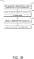
- FIG. 10 is a flow diagram of an example process for decoding pre-pended metadata in a data packet to route the data packet to an appropriate application server, wherein the data packet may be encrypted.
- an application server receives a data packet from a client device, the data packet destined for network services operating on an LwM2M server of a plurality of LwM2M servers.
- the network services may comprise one or more services that communicate with the client devices using UDP.
- the application server decodes pre-pended metadata in the data packet, the metadata representing information corresponding to the LwM2M server.
- the metadata may be encapsulated.
- the metadata may comprise an endpoint identifier, a connection identifier, uri-host and uri-port, and/or so forth.
- the application server identifies the LwM2M server based at least on the information corresponding to the LwM2M server.
- the application server routes the data packet to the LwM2M server.
Landscapes
- Engineering & Computer Science (AREA)
- Computer Security & Cryptography (AREA)
- Computer Networks & Wireless Communication (AREA)
- Signal Processing (AREA)
- Computer Hardware Design (AREA)
- Computing Systems (AREA)
- General Engineering & Computer Science (AREA)
- Business, Economics & Management (AREA)
- General Business, Economics & Management (AREA)
- Multimedia (AREA)
- Library & Information Science (AREA)
- Data Exchanges In Wide-Area Networks (AREA)
Abstract
Description
- This application claims priority to a co-pending, commonly owned
U.S. Provisional Patent Application No. 62/318,630 filed on March 14, 2019 - Lightweight Machine-to-Machine (LwM2M) is a standard from the Open Mobile Alliance (OMA) that is focused on constrained cellular and other M2M devices. The standard devices are an efficient device-server interface based on open Internet Engineering Task Force (IETF) standards such as Datagram Transport Layer Security (DTLS) and Constrained Application Protocol (CoAP). Even though the transport binding to non-Internet Protocol (IP) data delivery (NIDD) has been defined in the LwM2M 1.1 specification, there are a number of gaps not allowing full LwM2M functionality to work over NIDD. Consequentially, it is not possible for the LwM2M client to transparently switch between IP-based transport and NIDD-based transport to communicate with the same LwM2M server while using the same security modes.
- Standardization does not define DTLS and CoAP bindings to the NIDD-based transport. Instead, only unsecured LwM2M binding to the NIDD-based transport are defined. Only unencrypted communication over NIDD using the noSEC security is currently possible with LwM2M 1.1. Thus, bootstrapping and other operations using any security bindings mapped to DTLS (i.e., Pre-Shared Keys [PSK], Raw Public Keys [RPK], X.509) are not possible via NIDD.
- The detailed description is described with reference to the accompanying figures, in which the leftmost digit(s) of a reference number identifies the figure in which the reference number first appears. The use of the same reference numbers in different figures indicates similar or identical items.
-
FIG. 1 illustrates an example of network architecture for using LwM2M protocol transparently via both IP- based and non-IP-based (NIDD) connection. -
FIG. 2 is a block diagram showing various components of a protocol data unit. -
FIG. 3 is a block diagram showing various components of an illustrative LwM2M endpoint device. -
FIG. 4 is a block diagram showing various components of an illustrative application server (AS). -
FIG. 5 is a protocol model that includes a UDP socket wrapper layer. -
FIG. 6 is a protocol model that includes new layers for the NIDD Socket binding. -
FIG. 7 is a server-side protocol stack for processing NIDD messages. -
FIG. 8 is a flow diagram of an example process for transporting application-level protocol messages modeled over IP transport, using DTLS security modes over NIDD. -
FIG. 9 is a flow diagram of an example process for inserting metadata into an option field of a data layer. -
FIG. 10 is a flow diagram of an example process for decoding pre-pended metadata in a data packet to route the data packet to an appropriate application server. - This disclosure is directed to techniques for providing transparent LwM2M operations over non-IP data delivery, in which an LwM2M client may transparently connect to the same LwM2M server alternatively or concurrently via both IP-based and NIDD- based connectivity using all LwM2M functionality and security modes, including client- or server-initiated bootstrapping.
- LwM2M protocol uses an endpoint identifier (ID) to identify a specific client and then uses the client's incoming IP-address:Port-number combination to uniquely identify the LwM2M client or LwM2M server. In the CoAP protocol (RFC 7252), which underlies the LwM2M protocol, the client endpoint is solely identified by the IP address and User Datagram Protocol (UDP) port number. DTLS-based security modes are identified from the security context, which is also based on the IP-address:Port-number combination mapped to the specific credential or a credential ID (e.g., PSK-id) that is negotiated during the DTLS handshake and key exchange procedures.
- In some aspects a UDP socket wrapper layer is introduced between the UDP and NIDD interfaces and LwM2M client. The UDP socket wrapper encapsulates the underlying regular UDP socket for connecting over the IP transport, and new NIDD socket implementing a device-specific connectivity layer to the NIDD data connection. The NIDD socket may be an extension of the socket Application Programming Interface (API) to send data to the NIDD connection (e.g., encoding the data stream and sending it to the related interface over AT-command interface). The UDP socket wrapper may present the two underlying sockets to DTLS layer as a regular UDP socket.
- In some aspects the UDP socket wrapper includes a connection router layer, which may define whether to use UDP or NIDD connection. In one example, the connection router layer may implement a policy module that can randomly try interfaces or based at least on one or more conditions. For instance, the connection router module may use both IP-based and NIDD connections simultaneously or sequentially. Additionally, the connection router layer may implement an encapsulation layer to insert NIDD metadata for LwM2M routing into the data stream. For example, uri-host and uri-port options or CoAP/LwM2M endpoint client-IP parameter (ep), or other identifiable data may be inserted in the CoAP packet.
- The UDP socket wrapper may also be deployed as a separate device or an operating system (OS) stack layer. In this case, the functionality may be transparent to the upper layer client, and the protocol or connection type exposed to an LwM2M client may be represented as the UDP. Parameter update of connectivity object may be provided to determine the underlying switching between IP and non-IP based transports. In this case, the wrapping layer emulates all standard UDP parameters that may be returned by the UDP-type networking socket.
- In some aspects the NIDD interface implements an additional datagram wrapper layer, passing to the server necessary metadata to route encrypted datagrams on the server-side. The NIDD metadata that is sent in the NIDD frame is unparsed on the server-side to recover the metadata information (e.g., uri-host, uri-port, ep, etc.). The NIDD metadata is used to identify the uri-host and uri-port combination of a particular target LwM2M server, bootstrap server, CoAP server, and/or so forth. Thus, the NIDD metadata is used to route the datagram to an appropriate server.
- The techniques described herein may be implemented in a number of ways. Example implementations are provided below with reference to the following figures.
-
FIG. 1 illustrates example architecture for using LwM2M protocol transparently via both IP- based and non-IP-based (NIDD) connections. Thearchitecture 100 may include one or moreLwM2M endpoint devices 102 that may interface with anapplication server 104 over anetwork 106. Thenetwork 106 can be a cellular network that implements 2G, 3G, 4G, and long-term evolution (LTE), LTE advanced, high-speed data packet access (HSDPA), evolved high-speed packet access (HSPA+), universal mobile telecommunication system (UMTS), code-division multiple access (CDMA), global system for mobile communications (GSM), a local area network (LAN), a wide area network (WAN), and/or a collection of networks (e.g., the Internet). Thenetwork 106 can also be based on a low-power or short-range wireless communication (e.g., WiFi, Bluetooth, etc.) as opposed to radio communication over more extended distances such as in macrocells of a cellular network. - The
application server 104 may be hosted by an M2M service provider, network service provider, or application service provider. Theapplication server 104 may include general-purpose computers, such as desktop computers, tablet computers, laptop computers, servers (e.g., on-premise servers), or other electronic devices that are capable of receiving input, processing the input, and generating output data. Theapplication server 104 may store data in a distributed storage system, in which data may be stored for long periods of time and replicated to guarantee reliability. - The
application server 104 may provide data and processing redundancy, in which data processing and data storage may be scaled in response to demand. Further, in a networked deployment, new application servers may be added. Thus, theapplication server 104 can include a plurality of physical machines that may be grouped together and presented as a single computing system. Each physical machine of the plurality of physical machines may comprise a node in a cluster. Theapplication server 104 may also be in the form of virtual machines, such as virtual engines (VE) and virtual private servers (VPS). - The
LwM2M endpoint devices 102 may also include general-purpose computers and other electronic devices having a wireless communication function that can receive input, process the input, and generate output data. In various embodiments, theLwM2M endpoint devices 102 may include home automation devices, appliances, transportation devices, healthcare devices, Internet of Things (IoT) devices, phones, tablets, mobile devices, and other devices that can communicate over short- or long-range technologies. - Communication between the
LwM2M endpoint devices 102 and theapplication server 104 is provided as a client-server type of communication, where theLwM2M endpoint device 102 has data to report and acts as a client entity. Thus, theLwM2M endpoint device 102 may be referred to as a client device. In some embodiments, theapplication server 104 may communicate with multiple clients. The communication types supported by the client/server may include UDP/IP based communication type. The UDP/IP based communication type is suitable for remote data exchange with metering equipment via IP enabled networks, using various communication networks such as LAN or private or public WAN. The communication type may also include a non-IP communication type. The non-IP based communication type is suitable for use of protocols that have been optimized for a specific use and power consumption can be optimized using non-IP. While the illustrated embodiment shows two network connectivity interfaces - IP and NIDD, any number and type of supported interfaces may be implemented. - Generally, the following logical interfaces are defined between the
application server 104 and the client: bootstrapping being pre-provisioned or client or server-initiated, registration to register the client and its objects, object or resource access or device management to enable theapplication server 104 to access an object or resource, and information reporting for notifications with new resource values. - The
application server 104 can be a CoAP server, MQ Telemetry Transport for Sensor Networks (MQTT-SN) server, an LwM2M server, and/or a bootstrap server. Additionally, or alternatively, theapplication server 104 can include an intermediary server or an intermediate node in communication with additional servers (e.g.,bootstrap server 110,LwM2M server 112, etc.). Theapplication server 104 may receive a data packet from an LwM2M endpoint device (i.e., a client device) 102. The data packet may be destined for network services or anLwM2M application 108 operating on theapplication server 104 or other servers (e.g.,bootstrap server 110,LwM2M server 112, etc.). Various components of a protocol data unit are depicted inFIG. 2 . As shown inFIG. 2 , adatagram 208 sits inside adata packet 206, which is wrapped in aframe 202. In some aspects, themetadata 204 is pre-pended to correctly route thedatagram 208 which is passed down to the next layer (i.e., data link layer). -
FIG. 3 is a block diagram showing various components of anLwM2M endpoint device 300 that hosts a client. It is noted that theLwM2M endpoint device 300 as described herein can operate with more or fewer of the components shown herein. Additionally, theLwM2M endpoint device 300 as shown herein or portions thereof can serve as a representation of one or more of the client devices of the present system. - The
LwM2M endpoint device 300 may include acommunication interface 302, one ormore processors 304,hardware 306, andmemory 308. The client entity hosted on theLwM2M endpoint device 300 can support multiple communication types (i.e., IP/non-IP based communication). Thecommunication interface 302 may include wireless and/or wired communication components that enable theLwM2M endpoint device 300 to transmit data to and receive data from other networked devices. In at least one example, the one or more processor(s) 304 may be a central processing unit(s) (CPU), graphics processing unit(s) (GPU), both a CPU and GPU or any other sort of processing unit(s). Each of the one or more processor(s) 304 may have numerous arithmetic logic units (ALUs) that perform arithmetic and logical operations as well as one or more control units (CUs) that extract instructions and stored content from processor cache memory, and then executes these instructions by calling on the ALUs, as necessary during program execution. - The one or more processor(s) 304 may also be responsible for executing all computer applications stored in the memory, which can be associated with common types of volatile (RAM) and/or nonvolatile (ROM) memory. The
hardware 306 may include additional user interface, data communication, or data storage hardware. For example, the user interfaces may include a data output device (e.g., visual display, audio speakers), and one or more data input devices. The data input devices may include but are not limited to, combinations of one or more of keypads, keyboards, mouse devices, touch screens that accept gestures, microphones, voice or speech recognition devices, and any other suitable devices. - The
memory 308 may be implemented using computer-readable media, such as computer storage media. Computer-readable media includes, at least, two types of computer-readable media, namely computer storage media and communications media. Computer storage media includes volatile and nonvolatile, removable and non-removable media implemented in any method or technology for storage of information such as computer-readable instructions, data structures, program modules, or other data. Computer storage media includes, but is not limited to, RAM, ROM, EEPROM, flash memory or other memory technology, CD-ROM, digital versatile disks (DVD), high-definition multimedia/data storage disks, or other optical storage, magnetic cassettes, magnetic tape, magnetic disk storage or other magnetic storage devices, or any other non-transmission medium that can be used to store information for access by a computing device. In contrast, communication media may embody computer-readable instructions, data structures, program modules, or other data in a modulated data signal, such as a carrier wave, or other transmission mechanisms. Thememory 308 may also include a firewall. In some embodiments, the firewall may be implemented ashardware 306 in theLwM2M endpoint device 300. - The
processors 304 and thememory 308 of theLwM2M endpoint device 300 may implement an operating system 310 and amessaging module 312. The operating system 310 may include components that enable theLwM2M endpoint device 300 to receive and transmit data via various interfaces (e.g., user controls, communication interface, and/or memory input/output devices), as well as process data using theprocessors 304 to generate output. The operating system 310 may include a presentation component that presents the output (e.g., display the data on an electronic display, store the data in memory, transmit the data to another electronic device, etc.). Additionally, the operating system 310 may include other components that perform various additional functions generally associated with an operating system. - The
messaging module 312 may include routines, program instructions, objects, and/or data structures that perform particular tasks or implement particular abstract data types. For example, themessaging module 312 may include one or more instructions, which when executed by the one ormore processors 304 direct theLwM2M endpoint device 300 to perform operations related to transmitting application-level protocol (e.g., LwM2M/CoAP) messages. In one aspect, themessaging module 312 is configured to transmit a data packet that is destined for network services or an LwM2M application operating on the application server or other servers (e.g., bootstrap server, LwM2M server, etc.). Themessaging module 312 may be configured to transport messages using DTLS-based PSK, RPK, and X.509 security modes over NIDD. -
FIG. 4 is a block diagram showing various components of anapplication server 400. It is noted that theapplication server 400 as described herein can operate with more or fewer of the components shown herein. Additionally, theapplication server 400 as shown herein or portions thereof can serve as a representation of one or more of the servers of the present system. - The
application server 400 may include acommunication interface 402, one ormore processors 404,hardware 406, andmemory 408. Thecommunication interface 402 may include wireless and/or wired communication components that enable theapplication server 400 to transmit data to and receive data from other networked devices. In at least one example, the one or more processor(s) 404 may be a central processing unit(s) (CPU), graphics processing unit(s) (GPU), both a CPU and GPU or any other sort of processing unit(s). Each of the one or more processor(s) 404 may have numerous arithmetic logic units (ALUs) that perform arithmetic and logical operations as well as one or more control units (CUs) that extract instructions and stored content from processor cache memory, and then execute these instructions by calling on the ALUs, as necessary during program execution. - The one or more processor(s) 404 may also be responsible for executing all computer applications stored in the memory, which can be associated with common types of volatile (RAM) and/or nonvolatile (ROM) memory. The
hardware 406 may include additional user interface, data communication, or data storage hardware. For example, the user interfaces may include a data output device (e.g., visual display, audio speakers), and one or more data input devices. The data input devices may include but are not limited to, combinations of one or more of keypads, keyboards, mouse devices, touch screens that accept gestures, microphones, voice or speech recognition devices, and any other suitable devices. - The
memory 408 may be implemented using computer-readable media, such as computer storage media. Computer-readable media includes, at least, two types of computer-readable media, namely computer storage media and communications media. Computer storage media includes volatile and nonvolatile, removable and non-removable media implemented in any method or technology for storage of information such as computer-readable instructions, data structures, program modules, or other data. Computer storage media includes, but is not limited to, RAM, ROM, EEPROM, flash memory or other memory technology, CD-ROM, digital versatile disks (DVD), high-definition multimedia/data storage disks, or other optical storage, magnetic cassettes, magnetic tape, magnetic disk storage or other magnetic storage devices, or any other non-transmission medium that can be used to store information for access by a computing device. In contrast, communication media may embody computer-readable instructions, data structures, program modules, or other data in a modulated data signal, such as a carrier wave, or other transmission mechanisms. Thememory 408 may also include a firewall. In some embodiments, the firewall may be implemented ashardware 406 in theapplication server 400. - The
processors 404 and thememory 408 of theapplication server 400 may implement an operating system 410, adecoding module 412, and arouting module 414. The operating system 410 may include components that enable theapplication server 400 to receive and transmit data via various interfaces (e.g., user controls, communication interface, and/or memory input/output devices), as well as process data using theprocessors 404 to generate output. The operating system 410 may include a presentation component that presents the output (e.g., display the data on an electronic display, store the data in memory, transmit the data to another electronic device, etc.). Additionally, the operating system 410 may include other components that perform various additional functions generally associated with an operating system. - The
decoding module 412 and therouting module 414 may include routines, program instructions, objects, and/or data structures that perform particular tasks or implement particular abstract data types. For example, thedecoding module 412 may include one or more instructions which, when executed by the one ormore processors 404, direct theapplication server 300 to perform operations relating to un-parsing NIDD metadata in the NIDD frame. Thedecoding module 412 recovers the metadata information (e.g., uri-host, uri-port, ep, etc.) which is sufficient to identify the uri-host and uri-port combination of a particular target LwM2M, bootstrap, or CoAP server, recover the endpoint-id of a particular LwM2M client if not already identified by the external-ID or MSISDN, and route the datagram to an appropriate server. - The
decoding module 412 passes the metadata to therouting module 414. Therouting module 414 may include one or more instructions which, when executed by the one ormore processors 404, direct theapplication server 400 to perform operations related to mapping or routing application-level protocol messages (e.g., encrypted DTLS messages) or datagrams to an appropriate server (e.g., LwM2M, CoAP, bootstrap server). Therouting module 414 may route the messages or datagrams based at least on metadata such as ep, source port, uri-host, or uri-port options. -
FIG. 5 is a protocol model that includes a UDPsocket wrapper layer 502. In some aspects, an application server is in communication with a client using both IP-based and NIDD-based connectivity. - The
LwM2M protocol stack 504 usesCoAP 506 as the underlying transfer protocol over UDP.CoAP 506 defines the message header, request/response codes, message options, and retransmission mechanisms.CoAP 506 is an alternative to HyperText Transfer Protocol (HTTP) for Representational State Transfer (RESTful) APIs on devices and supports the methods of GET, POST, PUT, DELETE, which can be mapped to those of HTTP. Unlike HTTP, CoAP messages are exchanged asynchronously between CoAP endpoints over a datagram-oriented transport such as UDP. CoAP messages are encoded in a binary format allowing functionality to start with a 4-byte overhead. - The LwM2M architecture uses security protocols to secure communications between client and
server using DTLS 508.DTLS 508 is used to provide a secure channel between an LwM2M server and an LwM2M client for all efficient payloads. The efficient payloads can be a plain text for individual resources and binary TLV or JSON for resource batches (object or resource arrays). DTLS security modes include both pre-shared key and public key technology to support embedded devices. - The UDP
socket wrapper layer 502 is introduced between theUDP 510 andNIDD interfaces 512 andLwM2M client 514. The UDPsocket wrapper layer 502 includes anoverloaded UDP socket 516 and aconnection router 518. The UDPsocket wrapper layer 502 encapsulates the underlyingregular UDP socket 520 for connecting over theIP transport 524, and aNIDD socket 522 implementing device-specific connectivity layer to theNIDD data connection 512, for example, by encoding the data packets as base64 and sending them to the communication module over AT commands. The UDPsocket wrapper layer 502 may be a functionality extender exposing new parameters and methods. In one aspect, the UDPsocket wrapper layer 502 may add a new socket transport protocol/type parameter, e.g., Hybrid UDP (HUDP). The UDPsocket wrapper layer 502 may also completely hide theUDP 510 andNIDD interfaces 512 using standard sockets interface to datagram transport, e.g., UDP. - The UDP
socket wrapper layer 502 may be deployed as a separate device or operatingsystem stack layer 526, not as code as part of the software client. In this case, the functionality will be completely transparent to the upper layer client, and the client will have no knowledge about the underlying switching betweenIP 524 and non-IP based (e.g., NIDD 512) transports. In the completely transparent deployment option, the protocol/connection type exposed to the LwM2M client (either 1.0 or 1.1) may be represented as UDP. In this case, the UDP socket wrapper layer emulates all standard UDP parameters that may be returned by the UDP-type networking socket. To determine whether the client is currently connecting over NIDD or UDP/IP, the parameter update of a connectivity object may be provided. - The
connection router 518 may parse the incoming data stream and provide logic to route over either IP-based or NIDD-based connectivity. The routing may be generally implemented using a policy module. The policy module may use logic to try IP-based or non-IP based interfaces randomly or sequentially. Additionally, or alternatively, the policy module may attempt to connect to IP-based or non-IP based interfaces concurrently. In some aspects, the policy module may be rule-based. For example, the policy module may allow specific LwM2M operations only over IP (e.g., SOTA/FOTA). - The
connection router 518 also implements an encapsulation layer to insert NIDD metadata in the NIDD frame that can be unparsed on the server-side to correctly define the DTLS security context on both sides of the NIDD connection, and to correctly route the data (e.g., DTLS-encrypted or unencrypted CoAP underlying LwM2M) to a specific server such as LwM2M, bootstrap, or CoAP server. Typically, the minimal necessary combination in the IP-based protocols is to define two touples: source IP-address:UDP port and destination IP-address:UDP port to define the connection endpoints. To be able to signal this information outside of the encrypted DTLS datagrams, these parameters are mapped to a set of metadata values to be pre-pended to each datagram and serialized. Any serialization format (e.g., JSON, CBOR, etc.) may be implemented. In a serialized form, an additional element for mapping metadata is pre-pended to the byte payload, which may include an encrypted DTLS datagram. - In one aspect, new parameter mapping to UDP source-port can be defined as a new CoAP option. Either could be modeled after the TCP/UDP ephemeral ports from the same range, or a new range could be defined, e.g., 0,1,2, etc. For example, the data may be routed based at least on uri-host and uri-port options. Additionally, for further extensions, any CoAP-level option specified by the enumerated key and any CoAP query parameter specified by string key may be added to the metadata.
- In some aspects, the CoAP/LwM2M endpoint client-IP (i.e., ep) parameter may be inserted as metadata using simple framing. However, values corresponding to ep may be omitted if the originator is completely determined on the NIDD level by, for example, external-ID, MSISDN, and/or other identifiers. Similarly, the source port may be omitted if there is only one client application endpoint for each NIDD connection.
-
FIG. 6 is a client-side protocol model that includes new layers for the NIDD Socket binding. In the illustrated embodiment, the protocol model includes a new layer comprising a NIDDaddress resolution layer 602 and a metadata andencapsulation layer 604 that uses anew NIDD socket 606. When a client initiates bootstrapping overNIDD interface 608, security binding may be needed for the proper bootstrap. During deployment, the client may send the bootstrap message by writing to theNIDD socket 606 in the same way as to theUDP socket 610. During NIDD socket implementation, the NIDDaddress resolution layer 602 may use the same address semantics as the domain name system (DNS) address resolution, but to resolve to the address, NIDD semantics can be used for the security context of the DTLS session. TheNIDD socket 606 accepts the DTLS messages starting from the Handshake (ClientHello). The metadata andencapsulation layer 604 then wraps the DTLS messages into the metadata and passes to theNIDD 608 as a datagram. -
FIG. 7 is a server-side protocol stack. In the illustrated embodiment, the protocol model includes a new layer comprising a NIDDaddress resolution layer 702 and a metadata andencapsulation layer 704 that uses a specialized 'NIDD'socket 706. The networking traffic usesTCP interface 708 orIP interface 710 to deliver encapsulated messages comprising metadata. Therefore, there is a need to overload (extend) the IP socket with the specialized 'NIDD'socket 706. The 'NIDD'socket 706 may be a listening socket. Listening sockets can derive the origin TCP IP:port from incoming traffic. The 'NIDD'socket 706 may include the functions to decode incoming CBOR, extract metadata to be used for the security context, and pass the encrypted DTLS records to theDTLS layer 712. Similar to the client-side processing, the 'NIDD'socket 706 overloads the socket API, and handle address resolution and framing within the socket separately for the traffic destined to the NIDD as opposed to for the IP-based traffic. Additionally, the new layer may need the IP level configuration to route the message correctly to the intermediate nodes (e.g., application server) handling the NIDD conversion. This may be accomplished by concatenating the intermediate node name, address, or configuration to the device endpoint-ID for sending, for example, as.system.com/device-id, wherein the device-id could be any identifier that the intermediate application server may recognize (e.g., NB-IoT external-ID, MSISDN, CoAP/LwM2M endpoint-ID, or any combination thereof). - In one example, during deployment, an application server may receive, from a client device, a T8 NIDD API message with the data field containing the datagram in a T8 interface call (e.g., RESTful HTTP request). The message may include a device identifier corresponding to the client device. The device identifier may be provided in the external-ID or MSISDN field of the T8 interface as defined by 3GPP TS 29122. The external-ID or MSISDN may be used to map the communication to a target server (e.g., LwM2M, bootstrap, or CoAP server). If the application server cannot map the message based at least on the external-ID or MSISDN, the application server may consider data in the data field as a CBOR serialization and decode it. In turn, the application server may recover metadata such as uri-host, uri-port, and/or ep: endpoint-ID field in the wrapper to route the datagram to a particular server. The uri-host and uri-port combination may be used to identify the target LwM2M, bootstrap, or CoAP server. Additionally, the ep:endpoint-ID may be used to identify a particular LwM2M client if it is not already identified by the external-ID or MSISDN. Depending on the implementation, the target server may need the metadata information to create a security context. In this scenario, the datagram is forwarded in the CBOR envelope, or the metadata is passed in a separate data field. The target server then passes the datagram to the DTLS stack using the metadata to create a security context for the datagram.
-
FIGS. 8-10 presents illustrative processes 800-1000 for transporting application-level protocol messages modeled over IP transport, using DTLS security modes over NIDD. The processes 800-1000 are illustrated as a collection of blocks in a logical flow chart, which represents a sequence of operations that can be implemented in hardware, software, or a combination thereof. In the context of software, the blocks represent computer-executable instructions that, when executed by one or more processors, perform the recited operations. Generally, computer-executable instructions may include routines, programs, objects, components, data structures, and the like that perform particular functions or implement particular abstract data types. The order in which the operations are described is not intended to be construed as a limitation, and any number of the described blocks can be combined in any order and/or in parallel to implement the process. For discussion purposes, the processes 800-1000 are described with references toFIGS. 1-7 . -
FIG. 8 is a flow diagram of an example process for transporting application-level protocol messages modeled over IP transport, in some cases using DTLS security modes over NIDD. Various protocols may be used, depending upon embodiments. For example, CoAP, LwM2M protocol, MQ Telemetry Transport for Sensor Networks (MQTT-SN) protocol, and/or Quick User Datagram Protocol Internet Connections (QUIC) protocol may be implemented. Atblock 802, a client device establishes a connection over a NIDD socket to communicate with an application server using NIDD binding. The NIDD socket may be a listening socket. Atblock 804, the client device generates a datagram destined for a target server. The datagram may be encrypted or may be an unencrypted application protocol data. In some aspects, the datagram is generated when the DTLS handshake process has been completed. Atblock 806, the client device encapsulates the datagram in a serialized envelope including application-level protocol metadata, the metadata representing information corresponding to the target server. Various serializing format for the serialized envelop such as JSON and CBOR may be used. Atblock 808, the client device sends the datagram to the target server over NIDD-based transport. -
FIG. 9 is a flow diagram of an example process for inserting metadata into an option field of a data layer. Atblock 902, a client device establishes a connection over a NIDD socket to communicate with an application server using NIDD binding. Atblock 904, the client device generates an application-level protocol message, the message comprising an option field. The option field can comprise a connection identifier field of encrypted DTLS packets. Atblock 906, the client device inserts application-level protocol metadata in the option field, the metadata representing information corresponding to a target server. The target server comprises at least one of the CoAP server, MQTT-SN server, an LwM2M server, and/or a bootstrap server. Atblock 908, the client device passes the message to a NIDD layer as a datagram, wherein the datagram can comprise DTLS encrypted data or an unencrypted application protocol data. -
FIG. 10 is a flow diagram of an example process for decoding pre-pended metadata in a data packet to route the data packet to an appropriate application server, wherein the data packet may be encrypted. Atblock 1002, an application server receives a data packet from a client device, the data packet destined for network services operating on an LwM2M server of a plurality of LwM2M servers. The network services may comprise one or more services that communicate with the client devices using UDP. Atblock 1004, the application server decodes pre-pended metadata in the data packet, the metadata representing information corresponding to the LwM2M server. In various embodiments, the metadata may be encapsulated. Additionally, the metadata may comprise an endpoint identifier, a connection identifier, uri-host and uri-port, and/or so forth. Atblock 1006, the application server identifies the LwM2M server based at least on the information corresponding to the LwM2M server. Atblock 1008, the application server routes the data packet to the LwM2M server. - Although the subject matter has been described in language specific to structural features and/or methodological acts, it is to be understood that the subject matter defined in the appended claims is not necessarily limited to the specific features or acts described. Rather, the specific features and acts are disclosed as exemplary forms of implementing the claims.
Claims (15)
- One or more non-transitory computer-readable media storing computer-executable instructions that upon execution cause one or more processors to perform acts comprising:establishing a connection over a Non-Internet Protocol Data Delivery (NIDD) socket to communicate with an application server using NIDD binding;generating a datagram destined for a target server;encapsulating the datagram in a serialized envelope including application-level protocol metadata, the metadata representing information corresponding to the target server; andsending the datagram to the target server over NIDD-based transport.
- The one or more non-transitory computer-readable media of claim 1, wherein the acts further comprise:
wrapping the NIDD socket in a wrapper socket to emulate handling of Internet Protocol (IP)-based transport. - The one or more non-transitory computer-readable media of claim 1, wherein the datagram is an encrypted datagram generated when Datagram Transport Layer Security (DTLS) handshake process has been completed.
- The one or more non-transitory computer-readable media of claim 1, wherein the datagram is an unencrypted application protocol data.
- The one or more non-transitory computer-readable media of claim 1, wherein a serializing format for the serialized envelop is at least one of JavaScript Object Notation (JSON) and Concise Binary Object Representation (CBOR).
- A computer-implemented method, comprising:establishing a connection over a Non-Internet Protocol Data Delivery (NIDD) socket to communicate with an application server using NIDD binding;generating an application-level protocol message destined for a target server, the message comprising an option field;inserting application-level protocol metadata in the option field, the metadata representing information corresponding to a target server; andpassing the message to a NIDD layer as a datagram.
- The computer-implemented method of claim 6, wherein the target server comprises at least one of Constrained Application Protocol (CoAP) server, MQ Telemetry Transport for Sensor Networks (MQTT-SN) server, and a light weight machine-to-machine (LwM2M) server.
- The computer-implemented method of claim 6, wherein the protocol comprises at least one of Constrained Application Protocol (CoAP), light weight machine-to-machine (LwM2M) protocol, MQ Telemetry Transport for Sensor Networks (MQTT-SN) protocol, and Quick User Datagram Protocol Internet Connections (QUIC) protocol.
- The computer-implemented method of claim 6, wherein the option field comprises a connection identifier field.
- A system, comprising:
one or more non-transitory storage mediums configured to provide stored computer-readable instructions, the one or more non-transitory storage mediums coupled to one or more processors, the one or more processors configured to execute the computer-readable instructions to cause the one or more processors to:receive a data packet from a client device, the data packet destined for network services operating on a light weight machine-to-machine (LwM2M) server of a plurality of LwM2M servers;decode pre-pended metadata in the data packet, the metadata representing information corresponding to the LwM2M server;identify the LwM2M server based at least on the information corresponding to the LwM2M server; androute the data packet to the LwM2M server. - The system of claim 10, wherein the metadata comprises an endpoint identifier.
- The system of claim 10, wherein the metadata comprises a connection identifier.
- The system of claim 10, wherein the metadata comprises uri-host and uri-port.
- The system of claim 10, wherein the metadata is encapsulated.
- The system of claim 10, wherein the network services comprise one or more services that communicate with the client devices using UDP.
Applications Claiming Priority (2)
| Application Number | Priority Date | Filing Date | Title |
|---|---|---|---|
| US201962818630P | 2019-03-14 | 2019-03-14 | |
| US16/745,222 US11516263B2 (en) | 2019-03-14 | 2020-01-16 | Secure and transparent transport of application level protocols to non-IP data delivery communication channels |
Publications (2)
| Publication Number | Publication Date |
|---|---|
| EP3709684A1 true EP3709684A1 (en) | 2020-09-16 |
| EP3709684B1 EP3709684B1 (en) | 2024-02-14 |
Family
ID=69743065
Family Applications (1)
| Application Number | Title | Priority Date | Filing Date |
|---|---|---|---|
| EP20160278.6A Active EP3709684B1 (en) | 2019-03-14 | 2020-02-28 | Secure and transparent transport of application level protocols over non-ip data delivery communication channels |
Country Status (2)
| Country | Link |
|---|---|
| US (2) | US11516263B2 (en) |
| EP (1) | EP3709684B1 (en) |
Cited By (1)
| Publication number | Priority date | Publication date | Assignee | Title |
|---|---|---|---|---|
| CN115604339A (en) * | 2022-10-11 | 2023-01-13 | 北京数码视讯技术有限公司(Cn) | IP transparent transmission method and system based on UDP and QUIC protocols |
Families Citing this family (6)
| Publication number | Priority date | Publication date | Assignee | Title |
|---|---|---|---|---|
| CN115509153B (en) * | 2021-06-23 | 2024-09-27 | 中移物联网有限公司 | A secondary development method and device for narrowband Internet of Things NB-IoT communication module |
| CN113630466B (en) * | 2021-08-11 | 2023-09-26 | 深圳市欧瑞博科技股份有限公司 | Data transmission methods, systems, electronic devices and storage media |
| GB2616064B (en) * | 2022-02-28 | 2024-07-03 | Vodafone Group Services Ltd | Data transmission for loT devices |
| CN114938395B (en) * | 2022-05-11 | 2024-08-02 | 北京字节跳动网络技术有限公司 | Service response method, device, equipment and storage medium |
| US20250240702A1 (en) * | 2024-01-18 | 2025-07-24 | Verizon Patent And Licensing Inc. | Systems and methods for using external identifiers for routing |
| CN118972476A (en) * | 2024-07-16 | 2024-11-15 | 网易(杭州)网络有限公司 | A message processing method, device, computer equipment and storage medium |
Citations (2)
| Publication number | Priority date | Publication date | Assignee | Title |
|---|---|---|---|---|
| WO2009059061A1 (en) * | 2007-10-30 | 2009-05-07 | Qualcomm Incorporated | Methods and apparatus to provide a virtual network interface |
| US20160212108A1 (en) * | 2015-01-19 | 2016-07-21 | Intel IP Corporation | Systems, methods and devices for direct communication |
Family Cites Families (24)
| Publication number | Priority date | Publication date | Assignee | Title |
|---|---|---|---|---|
| WO2009029061A1 (en) | 2007-08-24 | 2009-03-05 | Mack Trucks, Inc. | Battery terminal connector bar with integral circuit protection |
| US20100142538A1 (en) * | 2008-12-09 | 2010-06-10 | Enfora, Inc. | M2M data router |
| US9021435B2 (en) * | 2010-05-20 | 2015-04-28 | Salesforce.Com, Inc. | Methods and systems for providing a user interface in a multi-tenant database environment |
| CN102548019B (en) * | 2010-12-15 | 2016-07-27 | 华为技术有限公司 | The foundation of common path and using method, the communication means of M2M and system |
| US9131330B2 (en) * | 2011-07-15 | 2015-09-08 | Telefonaktiebolaget L M Ericsson (Publ) | M2M services enablement architecture for cellular access networks |
| WO2014069968A1 (en) * | 2012-11-05 | 2014-05-08 | 엘지전자 주식회사 | Method and apparatus for updating information regarding specific resource in wireless communication system |
| JP6317817B2 (en) * | 2013-07-25 | 2018-04-25 | コンヴィーダ ワイヤレス, エルエルシー | End-to-end M2M service layer session |
| GB2518256A (en) * | 2013-09-13 | 2015-03-18 | Vodafone Ip Licensing Ltd | Communicating with a machine to machine device |
| CN103825888A (en) * | 2014-02-17 | 2014-05-28 | 北京奇虎科技有限公司 | Network Threat Processing Method and Equipment |
| KR102151031B1 (en) * | 2014-06-30 | 2020-09-02 | 삼성전자주식회사 | Method and apparatus for optimizing communications of low power devices |
| US10797935B2 (en) * | 2015-09-02 | 2020-10-06 | Convida Wireless, Llc | Methods and apparatus for enhancing native service layer device management functionality |
| US10146625B2 (en) * | 2015-10-28 | 2018-12-04 | Dell Products L.P. | Systems and methods for intelligent data manager for offloading of bulk data transfers |
| US20170149915A1 (en) * | 2015-11-25 | 2017-05-25 | Sap Se | System and method of feed data transmission |
| US10652085B2 (en) * | 2016-01-07 | 2020-05-12 | Lg Electronics Inc. | Method for setting configuration of non-IP data delivery (NDID) in wireless communication system and device for same |
| RU2705453C1 (en) * | 2016-01-26 | 2019-11-07 | Телефонактиеболагет Лм Эрикссон (Пабл) | Device and methods for device configuration m2m |
| WO2017131564A1 (en) * | 2016-01-27 | 2017-08-03 | Telefonaktiebolaget Lm Ericsson (Publ) | Method for setting up a secure connection between lwm2m devices |
| EP3826332B1 (en) * | 2016-05-06 | 2025-03-05 | Convida Wireless, LLC | Traffic steering at the service layer |
| US11240319B2 (en) * | 2017-03-02 | 2022-02-01 | Convida Wireless, Llc | Network service continuity without session continuity |
| EP3639612B1 (en) * | 2017-06-16 | 2023-09-20 | IPLA Holdings Inc. | Small data transfer, data buffering, and data management as a service in a communications network |
| US11388262B2 (en) * | 2017-12-29 | 2022-07-12 | Telefonaktiebolaget Lm Ericsson (Publ) | Compression context setup for data transmission for IOT devices |
| CN109995701B (en) * | 2017-12-29 | 2020-12-01 | 华为技术有限公司 | Device booting method, terminal and server |
| GB2575433B (en) * | 2018-06-26 | 2020-07-08 | Advanced Risc Mach Ltd | Automatic client device registration |
| US10834266B2 (en) * | 2018-07-23 | 2020-11-10 | Cisco Technology, Inc. | Process-efficient generation of data records for data communications involving groups or aggregates of IoT devices |
| MX2021003676A (en) * | 2018-10-04 | 2021-05-31 | Ericsson Telefon Ab L M | Methods providing dynamic nef tunnel allocation and related network nodes/functions. |
-
2020
- 2020-01-16 US US16/745,222 patent/US11516263B2/en active Active
- 2020-02-28 EP EP20160278.6A patent/EP3709684B1/en active Active
-
2022
- 2022-10-21 US US17/971,454 patent/US11909781B2/en active Active
Patent Citations (2)
| Publication number | Priority date | Publication date | Assignee | Title |
|---|---|---|---|---|
| WO2009059061A1 (en) * | 2007-10-30 | 2009-05-07 | Qualcomm Incorporated | Methods and apparatus to provide a virtual network interface |
| US20160212108A1 (en) * | 2015-01-19 | 2016-07-21 | Intel IP Corporation | Systems, methods and devices for direct communication |
Cited By (1)
| Publication number | Priority date | Publication date | Assignee | Title |
|---|---|---|---|---|
| CN115604339A (en) * | 2022-10-11 | 2023-01-13 | 北京数码视讯技术有限公司(Cn) | IP transparent transmission method and system based on UDP and QUIC protocols |
Also Published As
| Publication number | Publication date |
|---|---|
| US20230038179A1 (en) | 2023-02-09 |
| US11516263B2 (en) | 2022-11-29 |
| EP3709684B1 (en) | 2024-02-14 |
| US11909781B2 (en) | 2024-02-20 |
| US20200296141A1 (en) | 2020-09-17 |
Similar Documents
| Publication | Publication Date | Title |
|---|---|---|
| US11909781B2 (en) | Secure and transparent transport of application level protocols to non-IP data delivery communication channels | |
| EP3195566B1 (en) | Service layer interworking using mqtt protocol | |
| US10498831B2 (en) | Communication sessions at a CoAP protocol layer | |
| Alghamdi et al. | Security analysis of the constrained application protocol in the Internet of Things | |
| US10069800B2 (en) | Scalable intermediate network device leveraging SSL session ticket extension | |
| Thantharate et al. | Coap and mqtt based models to deliver software and security updates to iot devices over the air | |
| KR20220139389A (en) | Methods and apparatuses for enabling multi-host multipath secure transmission with QUIC | |
| US8817815B2 (en) | Traffic optimization over network link | |
| WO2018187135A1 (en) | A proxy for serving internet-of-things (iot) devices | |
| US12120028B1 (en) | Secure data routing with channel resiliency | |
| CN101827111A (en) | TCP (Transfer Control Protocol) linking method, network system, client end and server | |
| CN107113898A (en) | System, method and apparatus for the direct communication using PC5 agreements | |
| CN115296996B (en) | Data transmission method, over-the-air upgrade method, network equipment, network system | |
| EP3926932A1 (en) | Duplex load balancing for massive iot applications | |
| CN107360205A (en) | The transmission method and device of data message, system | |
| CN105978909A (en) | Transport layer encapsulation-based data transmission method, and data transmission apparatus and system | |
| KR20220024697A (en) | Packet Acknowledgment Technology for Better Network Traffic Management | |
| Chavan et al. | Secure CoAP using enhanced DTLS for Internet of things | |
| Bhatia et al. | Massive machine type communications over 5G using lean protocols and edge proxies | |
| US11818104B2 (en) | Anonymous proxying | |
| Moffa | Design and implementation of a DTN Convergence Layer Adapter based on the QUIC protocol | |
| KR101594897B1 (en) | Secure Communication System and Method for Building a Secure Communication Session between Lightweight Things | |
| WO2026031382A1 (en) | Communication method, apparatus, and system for mission session | |
| Mouri | Iot protocols and security | |
| Cassagnes et al. | An overlay architecture for achieving total flexibility in internet communications |
Legal Events
| Date | Code | Title | Description |
|---|---|---|---|
| PUAI | Public reference made under article 153(3) epc to a published international application that has entered the european phase |
Free format text: ORIGINAL CODE: 0009012 |
|
| STAA | Information on the status of an ep patent application or granted ep patent |
Free format text: STATUS: THE APPLICATION HAS BEEN PUBLISHED |
|
| AK | Designated contracting states |
Kind code of ref document: A1 Designated state(s): AL AT BE BG CH CY CZ DE DK EE ES FI FR GB GR HR HU IE IS IT LI LT LU LV MC MK MT NL NO PL PT RO RS SE SI SK SM TR |
|
| AX | Request for extension of the european patent |
Extension state: BA ME |
|
| STAA | Information on the status of an ep patent application or granted ep patent |
Free format text: STATUS: REQUEST FOR EXAMINATION WAS MADE |
|
| 17P | Request for examination filed |
Effective date: 20210316 |
|
| RBV | Designated contracting states (corrected) |
Designated state(s): AL AT BE BG CH CY CZ DE DK EE ES FI FR GB GR HR HU IE IS IT LI LT LU LV MC MK MT NL NO PL PT RO RS SE SI SK SM TR |
|
| STAA | Information on the status of an ep patent application or granted ep patent |
Free format text: STATUS: EXAMINATION IS IN PROGRESS |
|
| 17Q | First examination report despatched |
Effective date: 20220216 |
|
| GRAP | Despatch of communication of intention to grant a patent |
Free format text: ORIGINAL CODE: EPIDOSNIGR1 |
|
| RIC1 | Information provided on ipc code assigned before grant |
Ipc: H04L 9/40 20220101ALI20230804BHEP Ipc: H04W 4/70 20180101AFI20230804BHEP |
|
| STAA | Information on the status of an ep patent application or granted ep patent |
Free format text: STATUS: GRANT OF PATENT IS INTENDED |
|
| INTG | Intention to grant announced |
Effective date: 20230914 |
|
| GRAS | Grant fee paid |
Free format text: ORIGINAL CODE: EPIDOSNIGR3 |
|
| GRAA | (expected) grant |
Free format text: ORIGINAL CODE: 0009210 |
|
| STAA | Information on the status of an ep patent application or granted ep patent |
Free format text: STATUS: THE PATENT HAS BEEN GRANTED |
|
| AK | Designated contracting states |
Kind code of ref document: B1 Designated state(s): AL AT BE BG CH CY CZ DE DK EE ES FI FR GB GR HR HU IE IS IT LI LT LU LV MC MK MT NL NO PL PT RO RS SE SI SK SM TR |
|
| REG | Reference to a national code |
Ref country code: GB Ref legal event code: FG4D |
|
| REG | Reference to a national code |
Ref country code: CH Ref legal event code: EP |
|
| REG | Reference to a national code |
Ref country code: DE Ref legal event code: R096 Ref document number: 602020025510 Country of ref document: DE |
|
| REG | Reference to a national code |
Ref country code: IE Ref legal event code: FG4D |
|
| REG | Reference to a national code |
Ref country code: LT Ref legal event code: MG9D |
|
| REG | Reference to a national code |
Ref country code: NL Ref legal event code: MP Effective date: 20240214 |
|
| PG25 | Lapsed in a contracting state [announced via postgrant information from national office to epo] |
Ref country code: IS Free format text: LAPSE BECAUSE OF FAILURE TO SUBMIT A TRANSLATION OF THE DESCRIPTION OR TO PAY THE FEE WITHIN THE PRESCRIBED TIME-LIMIT Effective date: 20240614 |
|
| PG25 | Lapsed in a contracting state [announced via postgrant information from national office to epo] |
Ref country code: LT Free format text: LAPSE BECAUSE OF FAILURE TO SUBMIT A TRANSLATION OF THE DESCRIPTION OR TO PAY THE FEE WITHIN THE PRESCRIBED TIME-LIMIT Effective date: 20240214 |
|
| PG25 | Lapsed in a contracting state [announced via postgrant information from national office to epo] |
Ref country code: GR Free format text: LAPSE BECAUSE OF FAILURE TO SUBMIT A TRANSLATION OF THE DESCRIPTION OR TO PAY THE FEE WITHIN THE PRESCRIBED TIME-LIMIT Effective date: 20240515 |
|
| REG | Reference to a national code |
Ref country code: AT Ref legal event code: MK05 Ref document number: 1658096 Country of ref document: AT Kind code of ref document: T Effective date: 20240214 |
|
| PG25 | Lapsed in a contracting state [announced via postgrant information from national office to epo] |
Ref country code: HR Free format text: LAPSE BECAUSE OF FAILURE TO SUBMIT A TRANSLATION OF THE DESCRIPTION OR TO PAY THE FEE WITHIN THE PRESCRIBED TIME-LIMIT Effective date: 20240214 Ref country code: NL Free format text: LAPSE BECAUSE OF FAILURE TO SUBMIT A TRANSLATION OF THE DESCRIPTION OR TO PAY THE FEE WITHIN THE PRESCRIBED TIME-LIMIT Effective date: 20240214 Ref country code: RS Free format text: LAPSE BECAUSE OF FAILURE TO SUBMIT A TRANSLATION OF THE DESCRIPTION OR TO PAY THE FEE WITHIN THE PRESCRIBED TIME-LIMIT Effective date: 20240514 |
|
| PG25 | Lapsed in a contracting state [announced via postgrant information from national office to epo] |
Ref country code: ES Free format text: LAPSE BECAUSE OF FAILURE TO SUBMIT A TRANSLATION OF THE DESCRIPTION OR TO PAY THE FEE WITHIN THE PRESCRIBED TIME-LIMIT Effective date: 20240214 |
|
| PG25 | Lapsed in a contracting state [announced via postgrant information from national office to epo] |
Ref country code: AT Free format text: LAPSE BECAUSE OF FAILURE TO SUBMIT A TRANSLATION OF THE DESCRIPTION OR TO PAY THE FEE WITHIN THE PRESCRIBED TIME-LIMIT Effective date: 20240214 |
|
| PG25 | Lapsed in a contracting state [announced via postgrant information from national office to epo] |
Ref country code: RS Free format text: LAPSE BECAUSE OF FAILURE TO SUBMIT A TRANSLATION OF THE DESCRIPTION OR TO PAY THE FEE WITHIN THE PRESCRIBED TIME-LIMIT Effective date: 20240514 Ref country code: NO Free format text: LAPSE BECAUSE OF FAILURE TO SUBMIT A TRANSLATION OF THE DESCRIPTION OR TO PAY THE FEE WITHIN THE PRESCRIBED TIME-LIMIT Effective date: 20240514 Ref country code: NL Free format text: LAPSE BECAUSE OF FAILURE TO SUBMIT A TRANSLATION OF THE DESCRIPTION OR TO PAY THE FEE WITHIN THE PRESCRIBED TIME-LIMIT Effective date: 20240214 Ref country code: LT Free format text: LAPSE BECAUSE OF FAILURE TO SUBMIT A TRANSLATION OF THE DESCRIPTION OR TO PAY THE FEE WITHIN THE PRESCRIBED TIME-LIMIT Effective date: 20240214 Ref country code: IS Free format text: LAPSE BECAUSE OF FAILURE TO SUBMIT A TRANSLATION OF THE DESCRIPTION OR TO PAY THE FEE WITHIN THE PRESCRIBED TIME-LIMIT Effective date: 20240614 Ref country code: HR Free format text: LAPSE BECAUSE OF FAILURE TO SUBMIT A TRANSLATION OF THE DESCRIPTION OR TO PAY THE FEE WITHIN THE PRESCRIBED TIME-LIMIT Effective date: 20240214 Ref country code: GR Free format text: LAPSE BECAUSE OF FAILURE TO SUBMIT A TRANSLATION OF THE DESCRIPTION OR TO PAY THE FEE WITHIN THE PRESCRIBED TIME-LIMIT Effective date: 20240515 Ref country code: FI Free format text: LAPSE BECAUSE OF FAILURE TO SUBMIT A TRANSLATION OF THE DESCRIPTION OR TO PAY THE FEE WITHIN THE PRESCRIBED TIME-LIMIT Effective date: 20240214 Ref country code: ES Free format text: LAPSE BECAUSE OF FAILURE TO SUBMIT A TRANSLATION OF THE DESCRIPTION OR TO PAY THE FEE WITHIN THE PRESCRIBED TIME-LIMIT Effective date: 20240214 Ref country code: BG Free format text: LAPSE BECAUSE OF FAILURE TO SUBMIT A TRANSLATION OF THE DESCRIPTION OR TO PAY THE FEE WITHIN THE PRESCRIBED TIME-LIMIT Effective date: 20240214 Ref country code: AT Free format text: LAPSE BECAUSE OF FAILURE TO SUBMIT A TRANSLATION OF THE DESCRIPTION OR TO PAY THE FEE WITHIN THE PRESCRIBED TIME-LIMIT Effective date: 20240214 |
|
| PG25 | Lapsed in a contracting state [announced via postgrant information from national office to epo] |
Ref country code: PT Free format text: LAPSE BECAUSE OF FAILURE TO SUBMIT A TRANSLATION OF THE DESCRIPTION OR TO PAY THE FEE WITHIN THE PRESCRIBED TIME-LIMIT Effective date: 20240614 Ref country code: PL Free format text: LAPSE BECAUSE OF FAILURE TO SUBMIT A TRANSLATION OF THE DESCRIPTION OR TO PAY THE FEE WITHIN THE PRESCRIBED TIME-LIMIT Effective date: 20240214 |
|
| PG25 | Lapsed in a contracting state [announced via postgrant information from national office to epo] |
Ref country code: SE Free format text: LAPSE BECAUSE OF FAILURE TO SUBMIT A TRANSLATION OF THE DESCRIPTION OR TO PAY THE FEE WITHIN THE PRESCRIBED TIME-LIMIT Effective date: 20240214 Ref country code: PT Free format text: LAPSE BECAUSE OF FAILURE TO SUBMIT A TRANSLATION OF THE DESCRIPTION OR TO PAY THE FEE WITHIN THE PRESCRIBED TIME-LIMIT Effective date: 20240614 Ref country code: PL Free format text: LAPSE BECAUSE OF FAILURE TO SUBMIT A TRANSLATION OF THE DESCRIPTION OR TO PAY THE FEE WITHIN THE PRESCRIBED TIME-LIMIT Effective date: 20240214 Ref country code: LV Free format text: LAPSE BECAUSE OF FAILURE TO SUBMIT A TRANSLATION OF THE DESCRIPTION OR TO PAY THE FEE WITHIN THE PRESCRIBED TIME-LIMIT Effective date: 20240214 |
|
| REG | Reference to a national code |
Ref country code: CH Ref legal event code: PL |
|
| PG25 | Lapsed in a contracting state [announced via postgrant information from national office to epo] |
Ref country code: DK Free format text: LAPSE BECAUSE OF FAILURE TO SUBMIT A TRANSLATION OF THE DESCRIPTION OR TO PAY THE FEE WITHIN THE PRESCRIBED TIME-LIMIT Effective date: 20240214 |
|
| PG25 | Lapsed in a contracting state [announced via postgrant information from national office to epo] |
Ref country code: SM Free format text: LAPSE BECAUSE OF FAILURE TO SUBMIT A TRANSLATION OF THE DESCRIPTION OR TO PAY THE FEE WITHIN THE PRESCRIBED TIME-LIMIT Effective date: 20240214 |
|
| PG25 | Lapsed in a contracting state [announced via postgrant information from national office to epo] |
Ref country code: LU Free format text: LAPSE BECAUSE OF NON-PAYMENT OF DUE FEES Effective date: 20240228 |
|
| PG25 | Lapsed in a contracting state [announced via postgrant information from national office to epo] |
Ref country code: CH Free format text: LAPSE BECAUSE OF NON-PAYMENT OF DUE FEES Effective date: 20240229 |
|
| PG25 | Lapsed in a contracting state [announced via postgrant information from national office to epo] |
Ref country code: CZ Free format text: LAPSE BECAUSE OF FAILURE TO SUBMIT A TRANSLATION OF THE DESCRIPTION OR TO PAY THE FEE WITHIN THE PRESCRIBED TIME-LIMIT Effective date: 20240214 Ref country code: EE Free format text: LAPSE BECAUSE OF FAILURE TO SUBMIT A TRANSLATION OF THE DESCRIPTION OR TO PAY THE FEE WITHIN THE PRESCRIBED TIME-LIMIT Effective date: 20240214 |
|
| PG25 | Lapsed in a contracting state [announced via postgrant information from national office to epo] |
Ref country code: SK Free format text: LAPSE BECAUSE OF FAILURE TO SUBMIT A TRANSLATION OF THE DESCRIPTION OR TO PAY THE FEE WITHIN THE PRESCRIBED TIME-LIMIT Effective date: 20240214 |
|
| PG25 | Lapsed in a contracting state [announced via postgrant information from national office to epo] |
Ref country code: SM Free format text: LAPSE BECAUSE OF FAILURE TO SUBMIT A TRANSLATION OF THE DESCRIPTION OR TO PAY THE FEE WITHIN THE PRESCRIBED TIME-LIMIT Effective date: 20240214 Ref country code: SK Free format text: LAPSE BECAUSE OF FAILURE TO SUBMIT A TRANSLATION OF THE DESCRIPTION OR TO PAY THE FEE WITHIN THE PRESCRIBED TIME-LIMIT Effective date: 20240214 Ref country code: RO Free format text: LAPSE BECAUSE OF FAILURE TO SUBMIT A TRANSLATION OF THE DESCRIPTION OR TO PAY THE FEE WITHIN THE PRESCRIBED TIME-LIMIT Effective date: 20240214 Ref country code: LU Free format text: LAPSE BECAUSE OF NON-PAYMENT OF DUE FEES Effective date: 20240228 Ref country code: EE Free format text: LAPSE BECAUSE OF FAILURE TO SUBMIT A TRANSLATION OF THE DESCRIPTION OR TO PAY THE FEE WITHIN THE PRESCRIBED TIME-LIMIT Effective date: 20240214 Ref country code: DK Free format text: LAPSE BECAUSE OF FAILURE TO SUBMIT A TRANSLATION OF THE DESCRIPTION OR TO PAY THE FEE WITHIN THE PRESCRIBED TIME-LIMIT Effective date: 20240214 Ref country code: CZ Free format text: LAPSE BECAUSE OF FAILURE TO SUBMIT A TRANSLATION OF THE DESCRIPTION OR TO PAY THE FEE WITHIN THE PRESCRIBED TIME-LIMIT Effective date: 20240214 Ref country code: CH Free format text: LAPSE BECAUSE OF NON-PAYMENT OF DUE FEES Effective date: 20240229 |
|
| REG | Reference to a national code |
Ref country code: DE Ref legal event code: R097 Ref document number: 602020025510 Country of ref document: DE |
|
| PG25 | Lapsed in a contracting state [announced via postgrant information from national office to epo] |
Ref country code: MC Free format text: LAPSE BECAUSE OF FAILURE TO SUBMIT A TRANSLATION OF THE DESCRIPTION OR TO PAY THE FEE WITHIN THE PRESCRIBED TIME-LIMIT Effective date: 20240214 |
|
| PG25 | Lapsed in a contracting state [announced via postgrant information from national office to epo] |
Ref country code: MC Free format text: LAPSE BECAUSE OF FAILURE TO SUBMIT A TRANSLATION OF THE DESCRIPTION OR TO PAY THE FEE WITHIN THE PRESCRIBED TIME-LIMIT Effective date: 20240214 |
|
| PG25 | Lapsed in a contracting state [announced via postgrant information from national office to epo] |
Ref country code: IT Free format text: LAPSE BECAUSE OF FAILURE TO SUBMIT A TRANSLATION OF THE DESCRIPTION OR TO PAY THE FEE WITHIN THE PRESCRIBED TIME-LIMIT Effective date: 20240214 |
|
| REG | Reference to a national code |
Ref country code: BE Ref legal event code: MM Effective date: 20240229 |
|
| PLBE | No opposition filed within time limit |
Free format text: ORIGINAL CODE: 0009261 |
|
| STAA | Information on the status of an ep patent application or granted ep patent |
Free format text: STATUS: NO OPPOSITION FILED WITHIN TIME LIMIT |
|
| PG25 | Lapsed in a contracting state [announced via postgrant information from national office to epo] |
Ref country code: IT Free format text: LAPSE BECAUSE OF FAILURE TO SUBMIT A TRANSLATION OF THE DESCRIPTION OR TO PAY THE FEE WITHIN THE PRESCRIBED TIME-LIMIT Effective date: 20240214 |
|
| PG25 | Lapsed in a contracting state [announced via postgrant information from national office to epo] |
Ref country code: BE Free format text: LAPSE BECAUSE OF NON-PAYMENT OF DUE FEES Effective date: 20240229 |
|
| 26N | No opposition filed |
Effective date: 20241115 |
|
| PG25 | Lapsed in a contracting state [announced via postgrant information from national office to epo] |
Ref country code: IE Free format text: LAPSE BECAUSE OF NON-PAYMENT OF DUE FEES Effective date: 20240228 |
|
| PG25 | Lapsed in a contracting state [announced via postgrant information from national office to epo] |
Ref country code: IE Free format text: LAPSE BECAUSE OF NON-PAYMENT OF DUE FEES Effective date: 20240228 Ref country code: BE Free format text: LAPSE BECAUSE OF NON-PAYMENT OF DUE FEES Effective date: 20240229 |
|
| PG25 | Lapsed in a contracting state [announced via postgrant information from national office to epo] |
Ref country code: SI Free format text: LAPSE BECAUSE OF FAILURE TO SUBMIT A TRANSLATION OF THE DESCRIPTION OR TO PAY THE FEE WITHIN THE PRESCRIBED TIME-LIMIT Effective date: 20240214 |
|
| PG25 | Lapsed in a contracting state [announced via postgrant information from national office to epo] |
Ref country code: CY Free format text: LAPSE BECAUSE OF FAILURE TO SUBMIT A TRANSLATION OF THE DESCRIPTION OR TO PAY THE FEE WITHIN THE PRESCRIBED TIME-LIMIT; INVALID AB INITIO Effective date: 20200228 |
|
| PG25 | Lapsed in a contracting state [announced via postgrant information from national office to epo] |
Ref country code: HU Free format text: LAPSE BECAUSE OF FAILURE TO SUBMIT A TRANSLATION OF THE DESCRIPTION OR TO PAY THE FEE WITHIN THE PRESCRIBED TIME-LIMIT; INVALID AB INITIO Effective date: 20200228 |
|
| PG25 | Lapsed in a contracting state [announced via postgrant information from national office to epo] |
Ref country code: TR Free format text: LAPSE BECAUSE OF FAILURE TO SUBMIT A TRANSLATION OF THE DESCRIPTION OR TO PAY THE FEE WITHIN THE PRESCRIBED TIME-LIMIT Effective date: 20240214 |
|
| PGFP | Annual fee paid to national office [announced via postgrant information from national office to epo] |
Ref country code: GB Payment date: 20260121 Year of fee payment: 7 |
|
| PGFP | Annual fee paid to national office [announced via postgrant information from national office to epo] |
Ref country code: DE Payment date: 20260121 Year of fee payment: 7 |
|
| PGFP | Annual fee paid to national office [announced via postgrant information from national office to epo] |
Ref country code: FR Payment date: 20260121 Year of fee payment: 7 |