EP3709536A1 - Optical receiver and optical reception method - Google Patents
Optical receiver and optical reception method Download PDFInfo
- Publication number
- EP3709536A1 EP3709536A1 EP18876307.2A EP18876307A EP3709536A1 EP 3709536 A1 EP3709536 A1 EP 3709536A1 EP 18876307 A EP18876307 A EP 18876307A EP 3709536 A1 EP3709536 A1 EP 3709536A1
- Authority
- EP
- European Patent Office
- Prior art keywords
- light
- signal
- power
- local oscillation
- wavelengths
- Prior art date
- Legal status (The legal status is an assumption and is not a legal conclusion. Google has not performed a legal analysis and makes no representation as to the accuracy of the status listed.)
- Granted
Links
Images



Classifications
-
- H—ELECTRICITY
- H04—ELECTRIC COMMUNICATION TECHNIQUE
- H04B—TRANSMISSION
- H04B10/00—Transmission systems employing electromagnetic waves other than radio-waves, e.g. infrared, visible or ultraviolet light, or employing corpuscular radiation, e.g. quantum communication
- H04B10/60—Receivers
- H04B10/61—Coherent receivers
- H04B10/615—Arrangements affecting the optical part of the receiver
-
- H—ELECTRICITY
- H04—ELECTRIC COMMUNICATION TECHNIQUE
- H04B—TRANSMISSION
- H04B10/00—Transmission systems employing electromagnetic waves other than radio-waves, e.g. infrared, visible or ultraviolet light, or employing corpuscular radiation, e.g. quantum communication
- H04B10/07—Arrangements for monitoring or testing transmission systems; Arrangements for fault measurement of transmission systems
- H04B10/075—Arrangements for monitoring or testing transmission systems; Arrangements for fault measurement of transmission systems using an in-service signal
- H04B10/079—Arrangements for monitoring or testing transmission systems; Arrangements for fault measurement of transmission systems using an in-service signal using measurements of the data signal
- H04B10/0795—Performance monitoring; Measurement of transmission parameters
- H04B10/07953—Monitoring or measuring OSNR, BER or Q
-
- H—ELECTRICITY
- H04—ELECTRIC COMMUNICATION TECHNIQUE
- H04B—TRANSMISSION
- H04B10/00—Transmission systems employing electromagnetic waves other than radio-waves, e.g. infrared, visible or ultraviolet light, or employing corpuscular radiation, e.g. quantum communication
- H04B10/07—Arrangements for monitoring or testing transmission systems; Arrangements for fault measurement of transmission systems
- H04B10/075—Arrangements for monitoring or testing transmission systems; Arrangements for fault measurement of transmission systems using an in-service signal
- H04B10/079—Arrangements for monitoring or testing transmission systems; Arrangements for fault measurement of transmission systems using an in-service signal using measurements of the data signal
-
- H—ELECTRICITY
- H04—ELECTRIC COMMUNICATION TECHNIQUE
- H04B—TRANSMISSION
- H04B10/00—Transmission systems employing electromagnetic waves other than radio-waves, e.g. infrared, visible or ultraviolet light, or employing corpuscular radiation, e.g. quantum communication
- H04B10/07—Arrangements for monitoring or testing transmission systems; Arrangements for fault measurement of transmission systems
- H04B10/075—Arrangements for monitoring or testing transmission systems; Arrangements for fault measurement of transmission systems using an in-service signal
- H04B10/079—Arrangements for monitoring or testing transmission systems; Arrangements for fault measurement of transmission systems using an in-service signal using measurements of the data signal
- H04B10/0795—Performance monitoring; Measurement of transmission parameters
- H04B10/07955—Monitoring or measuring power
-
- H—ELECTRICITY
- H04—ELECTRIC COMMUNICATION TECHNIQUE
- H04B—TRANSMISSION
- H04B10/00—Transmission systems employing electromagnetic waves other than radio-waves, e.g. infrared, visible or ultraviolet light, or employing corpuscular radiation, e.g. quantum communication
- H04B10/50—Transmitters
- H04B10/572—Wavelength control
-
- H—ELECTRICITY
- H04—ELECTRIC COMMUNICATION TECHNIQUE
- H04J—MULTIPLEX COMMUNICATION
- H04J14/00—Optical multiplex systems
- H04J14/02—Wavelength-division multiplex systems
-
- H—ELECTRICITY
- H04—ELECTRIC COMMUNICATION TECHNIQUE
- H04B—TRANSMISSION
- H04B10/00—Transmission systems employing electromagnetic waves other than radio-waves, e.g. infrared, visible or ultraviolet light, or employing corpuscular radiation, e.g. quantum communication
- H04B10/60—Receivers
-
- H—ELECTRICITY
- H04—ELECTRIC COMMUNICATION TECHNIQUE
- H04B—TRANSMISSION
- H04B10/00—Transmission systems employing electromagnetic waves other than radio-waves, e.g. infrared, visible or ultraviolet light, or employing corpuscular radiation, e.g. quantum communication
- H04B10/60—Receivers
- H04B10/61—Coherent receivers
-
- H—ELECTRICITY
- H04—ELECTRIC COMMUNICATION TECHNIQUE
- H04B—TRANSMISSION
- H04B10/00—Transmission systems employing electromagnetic waves other than radio-waves, e.g. infrared, visible or ultraviolet light, or employing corpuscular radiation, e.g. quantum communication
- H04B10/60—Receivers
- H04B10/61—Coherent receivers
- H04B10/63—Homodyne, i.e. coherent receivers where the local oscillator is locked in frequency and phase to the carrier signal
-
- H—ELECTRICITY
- H04—ELECTRIC COMMUNICATION TECHNIQUE
- H04B—TRANSMISSION
- H04B10/00—Transmission systems employing electromagnetic waves other than radio-waves, e.g. infrared, visible or ultraviolet light, or employing corpuscular radiation, e.g. quantum communication
- H04B10/60—Receivers
- H04B10/61—Coherent receivers
- H04B10/64—Heterodyne, i.e. coherent receivers where, after the opto-electronic conversion, an electrical signal at an intermediate frequency [IF] is obtained
-
- H—ELECTRICITY
- H04—ELECTRIC COMMUNICATION TECHNIQUE
- H04B—TRANSMISSION
- H04B10/00—Transmission systems employing electromagnetic waves other than radio-waves, e.g. infrared, visible or ultraviolet light, or employing corpuscular radiation, e.g. quantum communication
- H04B10/60—Receivers
- H04B10/61—Coherent receivers
- H04B10/65—Intradyne, i.e. coherent receivers with a free running local oscillator having a frequency close but not phase-locked to the carrier signal
Definitions
- the present invention relates to an optical receiver and an optical reception method, and particularly relates to an optical receiver and an optical reception method that can calculate the number of wavelengths of a wavelength multiplexed signal and power of signal light.
- phase modulation-demodulation methods of which examples include not only binary phase modulation and quadrature phase modulation but also polarization-multiplexing quadrature phase modulation being excellent in optical frequency-use efficiency are under research and development because of balance of a transmission characteristic, implementation easiness, and cost.
- the binary phase modulation is also called binary phase shift keying (BPSK).
- the quadrature phase modulation is also called quadrature phase shift keying (QPSK).
- QPSK quadrature phase shift keying
- the polarization-multiplexing quadrature phase modulation is also called polarization multiplexing-quadrature phase shift keying (PM-QPSK).
- the wavelength multiplexed signal is also called a wavelength division multiplexing (WDM) signal.
- WDM wavelength division multiplexing
- PTL 1 describes a technique of calculating an optical-signal-to-noise ratio (OSNR) of received signal light.
- OSNR optical-signal-to-noise ratio
- a problem when an optical receiver receives a WDM signal is difficulty of monitoring the number of wavelengths and optical power per wavelength (optical power per carrier) of signal light when the WDM signal is input to the optical receiver.
- a measurement device having a spectral function such as an optical spectrum analyzer.
- optical power of a main signal is reduced because of being split, and further, the measurement device or a special dedicated device is necessary, thereby resulting in difficulty of improving performance, cost, and a size of the optical receiver.
- An object of the present invention is to provide a technique that can easily estimate the number of wavelengths of a WDM signal and optical power of signal light.
- An optical receiver according to the present invention includes:
- An optical reception method includes:
- the optical receiver and the optical reception method according to the present invention can easily estimate the number of wavelengths of a WDM signal and signal light power.
- Fig. 1 is a block diagram illustrating a configuration example of an optical transmission system 10 according to a first example embodiment of the present invention.
- the optical transmission system 10 includes an optical receiver 100, an optical transmitter 200, and an optical transmission path 210.
- the optical transmitter 200 performs multi-level phase modulation on a carrier by transmission data, generates a WDM signal resulting from wavelength multiplexing performed on signal light that has been subjected to the multi-level phase modulation, and transmits the WDM signal to the optical transmission path 210.
- the WDM signal propagated through the optical transmission path 210 is received by the optical receiver 100.
- the optical receiver 100 selects, from carriers included in the WDM signal, signal light having a wavelength that is a reception target, and demodulates the selected signal light.
- the optical receiver 100 according to the present example embodiment includes a digital coherent detection function for demodulating signal light on which the multi-level phase modulation has been performed by the optical transmitter 200.
- Fig. 2 is a block diagram illustrating a configuration example of the optical receiver 100 according to the first example embodiment.
- the optical receiver 100 includes an optical reception unit 110 and a control unit 120.
- the optical receiver 100 receives a WDM signal from the optical transmission path 210, and performs coherent detection of the WDM signal by using local oscillation (LO) light. Thereby, signal light selected from the WDM signal is detected, and is output as an electrical signal.
- the light reception unit 110 outputs power of the LO light and a bit error rate of the electrical signal to the control unit 120.
- the electrical signal is output to an outside of the optical receiver 100.
- the optical reception unit 110 serves as an optical reception means including the above-described function.
- the control unit 120 monitors the power of the LO light and the bit error rate of the electrical signal output from the optical reception unit 110, and calculates a signal-to-noise ratio (SNR) of the signal light, based on the power of the LO light and the bit error rate.
- SNR is a ratio of signal electric power of signal light to noise electric power.
- the control unit 120 estimates the number of wavelengths of the signal light included in the WDM signal and power per wavelength of the signal light.
- the control unit 120 serves as a control means including the above-described function.
- the optical receiver 100 acquires the number of wavelengths included in signal light and power per wavelength of the signal light, based on an SNR and power of LO light. As a result, the optical receiver 100 according to the first example embodiment achieves an advantageous effect that the number of wavelengths of a WDM signal and signal light power can be easily estimated.
- Fig. 3 is a block diagram illustrating a configuration example of an optical receiver 100 according to a second example embodiment of the present invention.
- description is made on more detailed examples of a configuration and operation of the optical receiver 100 described in the first example embodiment.
- the optical receiver 100 includes a local oscillation light source (LO) 111, a 90-degree optical hybrid (HYB) 112, a photoelectric conversion unit (HS-PD) 113, an analog-to-digital conversion unit (A/D) 114, and a signal processing unit (DSP) 115.
- the optical reception unit 110 includes these. Since a general configuration of a digital coherent receiver is known, the detailed description is omitted.
- the optical receiver 100 receives a WDM signal from the optical transmission path 210.
- the WDM signal is separated into in-phase signal light and quadrature phase signal light.
- Each of the separated pieces of the signal light interferes with LO light output by the local oscillation light source 111, and is then converted into a detection signal by the photoelectric conversion unit 113.
- the photoelectric conversion unit includes a light reception element such as a high-speed photodiode (HS-PD).
- LO light power P LO (LO light power) is notified from the local oscillation light source 111 to the control unit 120.
- the detection signal output from the photoelectric conversion unit 113 is sampled and converted into a digital signal by the analog-to-digital conversion unit 114 (analog-to-digital converter, A/D) 114.
- the signal processing unit (digital signal processor, DSP) 115 performs digital coherent demodulation processing on the digital signal output from the analog-to-digital conversion unit 114, and thereby generates an electrical signal.
- the electrical signal is a signal including transmission data.
- the signal processing unit 115 notifies the control unit 120 of a bit error rate (BER) of the electrical signal acquired based on the number of error corrections.
- BER bit error rate
- the control unit 120 acquires an SNR of the signal light, the number of wavelengths of the received WDM signal, and power per wavelength, based on the LO light power P LO notified from the local oscillation light source 111 and the BER notified from the signal processing unit 115. In addition, the control unit 120 controls LO light power P LO , based on the acquired number of wavelengths and the acquired power per wavelength.
- Fig. 4 is a block diagram illustrating a configuration example of the control unit 120.
- the control unit 120 includes an operation unit 121 and a storage unit 122.
- the storage unit 122 stores a look-up table (LUT) 123 and a program 124.
- the storage unit 122 is a tangible and non-transitory storage medium.
- As the storage unit 122 a semiconductor memory or a fixed magnetic disk device is used, but the storage unit 122 is not limited to these.
- the operation unit 121 a central processing unit (CPU) can be used.
- the operation unit 121 reads the program 124 from the storage unit 122 and executes the read program 124, thereby implementing the function of the control unit 120.
- the operation unit 121 is connected to the local oscillation light source 111 and the signal processing unit 115.
- the look-up table 123 is described below by using Fig. 5 .
- an SNR of signal light included in WDM light input to the optical receiver 100 is calculated.
- an SNR of the signal light is calculated by an electric circuit of the optical receiver 100.
- the shot noise is temporal fluctuation of noise that appears in a signal.
- electric power [dBm] of shot noise current I shot flowing in the light reception element of the photoelectric conversion unit 113 is represented by equation (5).
- I shot 2 ⁇ 2 qR N ch P sig + P ase + P LO
- Equation (7) is acquired from equation (1) to equation (6).
- Equation (9) A general relation equation between a BER and a Q value in which a complementary error function erfc is used is represented by equation (9).
- Q 2 ⁇ erfc ⁇ 1 2 ⁇ BER
- Inputting an actual value to equation (7) can acquire a relation between input power P sig of signal light per wavelength to the optical receiver 100 and a reception SNR.
- Using equation (8) can make conversion between an SNR and a Q value.
- Fig. 5 is a look-up table representing one example of calculation results of an SNR under a condition that LO light power P LO is +7, +9, +13, and +15 dBm in the cases where the number N ch of wavelengths of signal light is 1, 2, 16, 48, and 96.
- Fig. 5 is the result of calculating an SNR while changing LO light power, the number of wavelengths, and input power of signal light per wavelength.
- a table such as Fig. 5 is stored in the storage unit 122 as the look-up table (LUT) 123.
- FIG. 6 is a graph representing the example of the calculation results of an SNR in the cases where the number N ch of wavelengths is 1, 16, 48, and 96 when LO light power P LO is +7 dBm.
- the graph of Fig. 6 can be drawn based on the look-up table.
- the horizontal axis in Fig. 6 represents input power P sig (signal input power / ch) of the signal light per wavelength, and the vertical axis represents an SNR.
- SNRs at different values of LO light power are calculated, and from the calculation results, the number of wavelengths and input power P sig of the signal light per wavelength can be estimated. This estimation can be performed even when the number N ch of wavelengths and input power P sig of the signal light per wavelength is unknown.
- An actual SNR can be calculated by using equations (8) and (9) from a value of a BER output by the signal processing unit 115 and LO light power P LO output by the local oscillation light source 111.
- a condition that input power P sig and the number N ch of wavelengths of signal light at the intersection point between the SNR and the graph is the same in each of the figures indicates a current state of the signal light of the optical receiver 100.
- the combinations of the number N ch of wavelengths and input power P sig of the signal light may be narrowed.
- the estimated input power P sig and the estimated number N ch of wavelengths of signal light do not need to be exactly the same as values on the graph.
- input power P sig and the number N ch of wavelengths of the signal light associated with a point in an area ranging from a position of a point on the graph within a distance equal to or smaller than a predetermined value may be used as estimated values.
- an estimated result may be input power P sig and the number N ch of wavelengths of the signal light both of which are substantially the same between the cases.
- an estimated number N ch of wavelengths and estimated input power P sig of signal light are fixed, and LO light power P LO resulting in the optimum SNR can be acquired by using the look-up table.
- Fig. 8 is a look-up table that is the same as Fig. 5 and that represents calculation results of an SNR.
- Fig. 9 is a graph representing calculation results of an SNR when P LO is +13 dBm. Fig.
- LO light power P LO that optimizes an SNR is approximately +13 dBm (in the bold frame in Fig. 8 ). Accordingly, the control unit 120 controls the local oscillation light source 111 in such a way that P LO becomes +13 dBm, and thereby increases an SNR of signal light to approximately 16.6 dB ( Figs. 8 and 9 ), enabling improvement in a reception characteristic.
- Fig. 10 is a flowchart illustrating an example of an operation procedure of the control unit 120 in the second example embodiment.
- an SNR has been described as one of parameters.
- equation (8) conversion between an SNR and a Q value can be easily made. Accordingly, as illustrated in Fig. 10 , a combination of the number N ch of wavelengths and signal light power P sig can be estimated by using a Q value instead of an SNR, and LO light power P LO can be optimized.
- a relation between signal light power per wavelength and a Q value (or an SNR) is calculated by using the number of wavelengths and LO light power as parameters, and is stored as an LUT (step S01 in Fig. 10 ).
- the LUT is stored in the storage unit 122.
- a Q value is calculated from a BER of received signal light (step S02).
- equation (9) can be used.
- a combination of the number of wavelengths and signal light power per wavelength is extracted from the LUT (step S03).
- LO light power is changed, and in this state, a Q value of the signal light is re-calculated (step S04).
- the LUT is referred to, and the combination of the number of wavelengths and signal light power per wavelength is selected (step S05). At this time, the same combination as the combination extracted at the step S03 is selected, and from the combination, the number of wavelengths and the signal light power per wavelength are estimated (step S06).
- the LUT may be referred to based on the estimated number of wavelengths and the estimated signal light power per wavelength, and LO light power may be controlled in such a way that a Q value becomes optimum (step S07).
- the optical receiver 100 calculates an SNR or a Q value of input signal light, based on a BER output from the signal processing unit 115 and LO light power P LO output from the local oscillation light source 111.
- an SNR and a Q value of the signal light can be acquired by calculation without using a dedicated measurement device or a spectroscopic device, and further, the number N ch of wavelengths of a WDM signal and input power P sig of the signal light per wavelength can be estimated.
- the procedure of the present example embodiment does not depend on a bit rate and a modulation method of signal light. In other words, whether a transmission speed is 40 Gbps or 100 Gbps, the above-described procedure is not affected by the transmission speed.
- a modulation method of signal light is not limited to quadrature phase modulation.
- the procedure of the present example embodiment is also applicable to a WDM signal transmitted by binary or octal phase modulation, or to a transmitted WDM signal intensity-modulated by such as a non-return-to-zero (NRZ) signal or a return-to-zero (RZ) signal.
- NRZ non-return-to-zero
- RZ return-to-zero
- the present invention is also further applicable to a modulation method, such as m-value quadrature amplitude modulation (m-QAM), in which phase modulation and intensity modulation are combined.
- the first advantageous effect is that a measurement device for monitoring an SNR, an optical splitting device causing deterioration of a characteristic of main signal light, and the like are not required.
- the reason is that an SNR or a Q value is acquired by calculation using a BER output from the signal processing unit provided in the digital coherent receiver and LO light power P LO output from the local oscillation light source 111.
- the reason is also that by using this result, signal light power P sig per wavelength input to the optical receiver 100 and the number N ch of wavelengths can be estimated by calculation.
- the optical receiver 100 can acquire, by calculation, signal light power P sig per wavelength input to the optical receiver 100 and the number N ch of wavelengths, which are difficult to actually measure.
- the second advantageous effect is that LO light power P LO can be optimally controlled.
- the reason is that at the estimated signal light power P sig per wavelength and the estimated number N ch of wavelengths, calculation or referring to a look-up table can acquire LO light power P LO at which an optimum SNR can be achieved.
- An optical receiver including:
- control means acquires the number of wavelengths and the power per wavelength both of which are substantially the same between the cases.
- control means stores a look-up table in which a relation among the number of wavelengths, the power per wavelength, the signal-to-noise ratio, and the power of the local oscillation light is calculated in advance, and the control means acquires the number of wavelengths and the power per wavelength by using the look-up table.
- control means controls the power of the local oscillation light in such a way as to improve the calculated signal-to-noise ratio.
- optical receiver according to any one of the Supplementary Notes 1 to 4, wherein the control means uses a Q value instead of the signal-to-noise ratio.
- An optical reception method including:
- optical reception method wherein in two or more cases between which power of the local oscillation light is different, the number of wavelengths and the power per wavelength both of which are substantially the same between the cases are acquired.
- the optical reception method wherein the number of wavelengths and the power per wavelength are acquired by using a relation among the number of wavelengths, the power per wavelength, the signal-to-noise ratio, and the power of the local oscillation light.
- the optical reception method according to any one of the Supplementary Notes 6 to 8, further including: controlling the power of the local oscillation light in such a way as to improve the signal-to-noise ratio.
- a program of an optical receiver the program causing a computer of the optical receiver to execute:
Landscapes
- Engineering & Computer Science (AREA)
- Computer Networks & Wireless Communication (AREA)
- Signal Processing (AREA)
- Physics & Mathematics (AREA)
- Electromagnetism (AREA)
- Optical Communication System (AREA)
Abstract
Description
- The present invention relates to an optical receiver and an optical reception method, and particularly relates to an optical receiver and an optical reception method that can calculate the number of wavelengths of a wavelength multiplexed signal and power of signal light.
- In a long-distance optical transmission system of an ultra-high speed equal to or higher than 100 gigabits per second (Gb/s), a digital coherent transmission method adopting phase modulation in place of a general transmission method using intensity modulation is considered to be promising. Among phase modulation methods, particularly, modulation-demodulation methods of which examples include not only binary phase modulation and quadrature phase modulation but also polarization-multiplexing quadrature phase modulation being excellent in optical frequency-use efficiency are under research and development because of balance of a transmission characteristic, implementation easiness, and cost. The binary phase modulation is also called binary phase shift keying (BPSK). The quadrature phase modulation is also called quadrature phase shift keying (QPSK). The polarization-multiplexing quadrature phase modulation is also called polarization multiplexing-quadrature phase shift keying (PM-QPSK).
- In an optical receiver used in a digital coherent transmission method, it is necessary to measure parameters such as the number of wavelengths of a wavelength multiplexed signal and optical power of signal light included in the wavelength multiplexed signal, and to perform monitoring of a reception state and optimization of reception quality by using the measured parameters. The wavelength multiplexed signal is also called a wavelength division multiplexing (WDM) signal. In relation to the present invention,
PTL 1 describes a technique of calculating an optical-signal-to-noise ratio (OSNR) of received signal light. - [PTL 1] Japanese Unexamined Patent Application Publication No.
2014-165895 - A problem when an optical receiver receives a WDM signal is difficulty of monitoring the number of wavelengths and optical power per wavelength (optical power per carrier) of signal light when the WDM signal is input to the optical receiver. For example, in order to measure the number of wavelengths and optical power per wavelength of a received WDM signal, it is necessary to split received signal light, and to measure the number of wavelengths and optical power by connection of a measurement device having a spectral function, such as an optical spectrum analyzer. In such a configuration, there is a problem that optical power of a main signal is reduced because of being split, and further, the measurement device or a special dedicated device is necessary, thereby resulting in difficulty of improving performance, cost, and a size of the optical receiver.
- An object of the present invention is to provide a technique that can easily estimate the number of wavelengths of a WDM signal and optical power of signal light.
- An optical receiver according to the present invention includes:
- an optical reception means for receiving wavelength multiplexed light including signal light, converting the signal light into an electrical signal by coherent detection of the signal light performed by using local oscillation light, and outputting power of the local oscillation light, a bit error rate of the electrical signal, and the electrical signal; and
- a control means for monitoring the power of the local oscillation light and the bit error rate, calculating a signal-to-noise ratio of the signal light, based on the power of the local oscillation light and the bit error rate, and acquiring the number of wavelengths of the wavelength multiplexed light and power per wavelength of the signal light, based on the signal-to-noise ratio and the power of the local oscillation light.
- An optical reception method according to the present invention includes:
- receiving wavelength multiplexed light including signal light;
- converting the signal light into an electrical signal by coherent detection of the signal light performed by using local oscillation light;
- outputting power of the local oscillation light, a bit error rate of the signal light, and the electrical signal;
- monitoring the power of the local oscillation light and the bit error rate;
- calculating a signal-to-noise ratio of the signal light, based on the power of the local oscillation light and the bit error rate; and
- acquiring the number of wavelengths of the wavelength multiplexed light and power per wavelength of the signal light, based on the signal-to-noise ratio and the power of the local oscillation light.
- The optical receiver and the optical reception method according to the present invention can easily estimate the number of wavelengths of a WDM signal and signal light power.
-
-
Fig. 1 is a block diagram illustrating a configuration example of anoptical transmission system 10 according to a first example embodiment. -
Fig. 2 is a block diagram illustrating a configuration example of anoptical receiver 100 according to the first example embodiment. -
Fig. 3 is a block diagram illustrating a configuration example of anoptical receiver 100 according to a second example embodiment. -
Fig. 4 is a block diagram illustrating a configuration example of acontrol unit 120. -
Fig. 5 is one example of calculation results (LUT) of an SNR. -
Fig. 6 is a graph of an example of calculation results of an SNR when PLO is +7 dBm. -
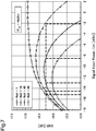
Fig. 7 is a graph of an example of calculation results of an SNR when PLO is +9 dBm. -
Fig. 8 is one example of calculation results (LUT) of an SNR. -
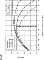
Fig. 9 is a graph representing an SNR when PLO is +13 dBm. -
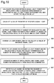
Fig. 10 is a flowchart illustrating an example of an operation procedure of acontrol unit 120. - Hereinafter, example embodiments of the present invention are described. Each arrow in the block diagrams illustrating the example embodiments exemplifies a direction of a signal for illustration, but does not limit the direction of the signal. The same reference signs are attached to aforementioned constituent elements, and the overlapping description is omitted.
-
Fig. 1 is a block diagram illustrating a configuration example of anoptical transmission system 10 according to a first example embodiment of the present invention. Theoptical transmission system 10 includes anoptical receiver 100, anoptical transmitter 200, and anoptical transmission path 210. Theoptical transmitter 200 performs multi-level phase modulation on a carrier by transmission data, generates a WDM signal resulting from wavelength multiplexing performed on signal light that has been subjected to the multi-level phase modulation, and transmits the WDM signal to theoptical transmission path 210. The WDM signal propagated through theoptical transmission path 210 is received by theoptical receiver 100. Theoptical receiver 100 selects, from carriers included in the WDM signal, signal light having a wavelength that is a reception target, and demodulates the selected signal light. Theoptical receiver 100 according to the present example embodiment includes a digital coherent detection function for demodulating signal light on which the multi-level phase modulation has been performed by theoptical transmitter 200. -
Fig. 2 is a block diagram illustrating a configuration example of theoptical receiver 100 according to the first example embodiment. Theoptical receiver 100 includes anoptical reception unit 110 and acontrol unit 120. Theoptical receiver 100 receives a WDM signal from theoptical transmission path 210, and performs coherent detection of the WDM signal by using local oscillation (LO) light. Thereby, signal light selected from the WDM signal is detected, and is output as an electrical signal. Thelight reception unit 110 outputs power of the LO light and a bit error rate of the electrical signal to thecontrol unit 120. The electrical signal is output to an outside of theoptical receiver 100. Theoptical reception unit 110 serves as an optical reception means including the above-described function. - The
control unit 120 monitors the power of the LO light and the bit error rate of the electrical signal output from theoptical reception unit 110, and calculates a signal-to-noise ratio (SNR) of the signal light, based on the power of the LO light and the bit error rate. An SNR is a ratio of signal electric power of signal light to noise electric power. Based on the SNR and the power of the LO light, thecontrol unit 120 estimates the number of wavelengths of the signal light included in the WDM signal and power per wavelength of the signal light. Thecontrol unit 120 serves as a control means including the above-described function. - The
optical receiver 100 acquires the number of wavelengths included in signal light and power per wavelength of the signal light, based on an SNR and power of LO light. As a result, theoptical receiver 100 according to the first example embodiment achieves an advantageous effect that the number of wavelengths of a WDM signal and signal light power can be easily estimated. -
Fig. 3 is a block diagram illustrating a configuration example of anoptical receiver 100 according to a second example embodiment of the present invention. In the second example embodiment, description is made on more detailed examples of a configuration and operation of theoptical receiver 100 described in the first example embodiment. - The
optical receiver 100 according to the second example embodiment includes a local oscillation light source (LO) 111, a 90-degree optical hybrid (HYB) 112, a photoelectric conversion unit (HS-PD) 113, an analog-to-digital conversion unit (A/D) 114, and a signal processing unit (DSP) 115. Theoptical reception unit 110 includes these. Since a general configuration of a digital coherent receiver is known, the detailed description is omitted. - The
optical receiver 100 receives a WDM signal from theoptical transmission path 210. By the 90-degree optical hybrid (HYB) 112, the WDM signal is separated into in-phase signal light and quadrature phase signal light. Each of the separated pieces of the signal light interferes with LO light output by the localoscillation light source 111, and is then converted into a detection signal by thephotoelectric conversion unit 113. The photoelectric conversion unit includes a light reception element such as a high-speed photodiode (HS-PD). LO light power PLO (LO light power) is notified from the localoscillation light source 111 to thecontrol unit 120. The detection signal output from thephotoelectric conversion unit 113 is sampled and converted into a digital signal by the analog-to-digital conversion unit 114 (analog-to-digital converter, A/D) 114. - The signal processing unit (digital signal processor, DSP) 115 performs digital coherent demodulation processing on the digital signal output from the analog-to-
digital conversion unit 114, and thereby generates an electrical signal. The electrical signal is a signal including transmission data. Thesignal processing unit 115 notifies thecontrol unit 120 of a bit error rate (BER) of the electrical signal acquired based on the number of error corrections. - The
control unit 120 acquires an SNR of the signal light, the number of wavelengths of the received WDM signal, and power per wavelength, based on the LO light power PLO notified from the localoscillation light source 111 and the BER notified from thesignal processing unit 115. In addition, thecontrol unit 120 controls LO light power PLO, based on the acquired number of wavelengths and the acquired power per wavelength. -
Fig. 4 is a block diagram illustrating a configuration example of thecontrol unit 120. Thecontrol unit 120 includes anoperation unit 121 and astorage unit 122. Thestorage unit 122 stores a look-up table (LUT) 123 and aprogram 124. Thestorage unit 122 is a tangible and non-transitory storage medium. As thestorage unit 122, a semiconductor memory or a fixed magnetic disk device is used, but thestorage unit 122 is not limited to these. As theoperation unit 121, a central processing unit (CPU) can be used. Theoperation unit 121 reads theprogram 124 from thestorage unit 122 and executes theread program 124, thereby implementing the function of thecontrol unit 120. Theoperation unit 121 is connected to the localoscillation light source 111 and thesignal processing unit 115. The look-up table 123 is described below by usingFig. 5 . - Next, a procedure of calculating an SNR in the
optical receiver 100 is described. First, an SNR of signal light included in WDM light input to theoptical receiver 100 is calculated. In the present example embodiment, an SNR of the signal light is calculated by an electric circuit of theoptical receiver 100. - It is assumed that power of each piece of signal light input to the
optical receiver 100 is Psig [W], LO light power is PLO [W], and light reception sensitivity of a light reception element of thephotoelectric conversion unit 113 is R [A/W]. In this case, electric power [dBm] of a PD current Isig flowing at the time of coherent detection of signal light performed by LO light is represented by equation (1). In the following equations (1) to (7), electric power represented with [dBm] indicates electric power in a reception band of theoptical receiver 100.
- Assuming that power of amplified spontaneous emission (ASE) noise light input to the
optical receiver 100 is Pase [W], electric power [dBm] of beat noise current Iase-LO of the ASE noise light and LO light is represented by equation (2).
- Electric power [dBm] of beat noise current Iase-ase of pieces of the ASE noise light is represented by equation (3).

- Electric power [dBm] of beat noise current Isig-sig of pieces of the signal light input to the
optical receiver 100 and having the number Nch of wavelengths is represented by equation (4).
- Next, a term concerning shot noise of the
optical receiver 100 is acquired. The shot noise is temporal fluctuation of noise that appears in a signal. Assuming that an electron charge is q [C], electric power [dBm] of shot noise current Ishot flowing in the light reception element of thephotoelectric conversion unit 113 is represented by equation (5).
- Assuming that the Boltzmann constant is k, a temperature of an amplifier is T [K], and a load of a circuit is RL [Ω], a thermal noise current Ithermal [dBm] of the circuit of the
optical receiver 100 is represented by equation (6).
- Since an SNR of the signal light input to the
optical receiver 100 is a ratio between power of the input signal light and noise power, equation (7) is acquired from equation (1) to equation (6).
- A relation between a reception Q value and an SNR in a quadrature phase modulation signal is represented by equation (8).

- A general relation equation between a BER and a Q value in which a complementary error function erfc is used is represented by equation (9).

- Inputting an actual value to equation (7) can acquire a relation between input power Psig of signal light per wavelength to the
optical receiver 100 and a reception SNR. Using equation (8) can make conversion between an SNR and a Q value. -
Fig. 5 is a look-up table representing one example of calculation results of an SNR under a condition that LO light power PLO is +7, +9, +13, and +15 dBm in the cases where the number Nch of wavelengths of signal light is 1, 2, 16, 48, and 96.Fig. 5 is the result of calculating an SNR while changing LO light power, the number of wavelengths, and input power of signal light per wavelength. A table such asFig. 5 is stored in thestorage unit 122 as the look-up table (LUT) 123.Fig. 6 is a graph representing the example of the calculation results of an SNR in the cases where the number Nch of wavelengths is 1, 16, 48, and 96 when LO light power PLO is +7 dBm. The graph ofFig. 6 can be drawn based on the look-up table. The horizontal axis inFig. 6 represents input power Psig (signal input power / ch) of the signal light per wavelength, and the vertical axis represents an SNR. - When signal light is actually input to the
optical receiver 100, SNRs at different values of LO light power are calculated, and from the calculation results, the number of wavelengths and input power Psig of the signal light per wavelength can be estimated. This estimation can be performed even when the number Nch of wavelengths and input power Psig of the signal light per wavelength is unknown. An actual SNR can be calculated by using equations (8) and (9) from a value of a BER output by thesignal processing unit 115 and LO light power PLO output by the localoscillation light source 111. - First, when a value of an SNR in the vertical axis in
Fig. 6 is fixed to a calculated value based on received signal light, combinations of the number Nch of wavelengths and input power Psig of the signal light per wavelength are limited to several intersection points on the graph. The following describes the case where a calculated SNR is 16.0 dB.Fig. 6 illustrates that the horizontal axis of SNR = 16.0 dB intersects with the graph at five points. -
Fig. 7 is a graph of an example of calculation results of an SNR when LO light power PLO is +9 dBm. It is assumed that when LO light power PLO is increased to +9 dBm, the calculation result of an SNR becomes 16.3 dB. Also inFig. 7 , the horizontal axis of SNR = 16.3 dB intersects with the graph at five points. However, the number Nch of wavelengths input to theoptical receiver 100 and input power Psig ("signal input power / ch") of signal light are the same as those in the case ofFig. 6 . Accordingly, it can be estimated that inFigs. 6 and7 , a condition that input power Psig and the number Nch of wavelengths of signal light at the intersection point between the SNR and the graph is the same in each of the figures indicates a current state of the signal light of theoptical receiver 100. In the present example embodiment, fromFigs. 6 and7 , it can be estimated that the case where the combination of the number Nch of wavelengths and input power of signal light is Nch = 48 and Psig = -8.5 dBm/ch is a condition of the currently input signal light. When two or more combinations of the number Nch of wavelengths and input power Psig of the signal light remain at this time, by the LO light power PLO further changed to a different value, the combinations of the number Nch of wavelengths and input power Psig of the signal light may be narrowed. - In
Figs. 6 and7 , the estimated input power Psig and the estimated number Nch of wavelengths of signal light do not need to be exactly the same as values on the graph. For example, input power Psig and the number Nch of wavelengths of the signal light associated with a point in an area ranging from a position of a point on the graph within a distance equal to or smaller than a predetermined value may be used as estimated values. In other words, in the cases of two or more cases between which LO light power PLO is different, an estimated result may be input power Psig and the number Nch of wavelengths of the signal light both of which are substantially the same between the cases. - Next, optimization of LO light power PLO is described. In a general digital coherent receiver, it has been difficult to optimally control LO light power PLO which is an important parameter affecting a reception characteristic. For example, when the number of received wavelengths changes from one wavelength to several tens of wavelengths, it has been difficult to monitor the number Nch of wavelengths of a WDM signal and input power Psig of the signal light per wavelength, and thus, it has been also difficult to optimally control LO light power.
- According to a procedure of the present example embodiment, an estimated number Nch of wavelengths and estimated input power Psig of signal light are fixed, and LO light power PLO resulting in the optimum SNR can be acquired by using the look-up table.
Fig. 8 is a look-up table that is the same asFig. 5 and that represents calculation results of an SNR.Fig. 9 is a graph representing calculation results of an SNR when PLO is +13 dBm.Fig. 8 reveals that in the case of "Nch = 48 as the above-estimated number of wavelengths and Psig = -8.5 dBm as the above-estimated input power of signal light", LO light power PLO that optimizes an SNR is approximately +13 dBm (in the bold frame inFig. 8 ). Accordingly, thecontrol unit 120 controls the localoscillation light source 111 in such a way that PLO becomes +13 dBm, and thereby increases an SNR of signal light to approximately 16.6 dB (Figs. 8 and9 ), enabling improvement in a reception characteristic. -
Fig. 10 is a flowchart illustrating an example of an operation procedure of thecontrol unit 120 in the second example embodiment. In the description using the look-up table, an SNR has been described as one of parameters. As represented in equation (8), conversion between an SNR and a Q value can be easily made. Accordingly, as illustrated inFig. 10 , a combination of the number Nch of wavelengths and signal light power Psig can be estimated by using a Q value instead of an SNR, and LO light power PLO can be optimized. - First, a relation between signal light power per wavelength and a Q value (or an SNR) is calculated by using the number of wavelengths and LO light power as parameters, and is stored as an LUT (step S01 in
Fig. 10 ). The LUT is stored in thestorage unit 122. Next, a Q value is calculated from a BER of received signal light (step S02). In the calculation of a Q value, equation (9) can be used. Then, based on the calculation result of a Q value and LO light power, a combination of the number of wavelengths and signal light power per wavelength is extracted from the LUT (step S03). Then, LO light power is changed, and in this state, a Q value of the signal light is re-calculated (step S04). Based on the changed LO light power and the re-calculated Q value, the LUT is referred to, and the combination of the number of wavelengths and signal light power per wavelength is selected (step S05). At this time, the same combination as the combination extracted at the step S03 is selected, and from the combination, the number of wavelengths and the signal light power per wavelength are estimated (step S06). - Further, the LUT may be referred to based on the estimated number of wavelengths and the estimated signal light power per wavelength, and LO light power may be controlled in such a way that a Q value becomes optimum (step S07).
- Thus, the
optical receiver 100 according to the second example embodiment calculates an SNR or a Q value of input signal light, based on a BER output from thesignal processing unit 115 and LO light power PLO output from the localoscillation light source 111. As a result, an SNR and a Q value of the signal light can be acquired by calculation without using a dedicated measurement device or a spectroscopic device, and further, the number Nch of wavelengths of a WDM signal and input power Psig of the signal light per wavelength can be estimated. - The procedure of the present example embodiment does not depend on a bit rate and a modulation method of signal light. In other words, whether a transmission speed is 40 Gbps or 100 Gbps, the above-described procedure is not affected by the transmission speed. A modulation method of signal light is not limited to quadrature phase modulation. The procedure of the present example embodiment is also applicable to a WDM signal transmitted by binary or octal phase modulation, or to a transmitted WDM signal intensity-modulated by such as a non-return-to-zero (NRZ) signal or a return-to-zero (RZ) signal. The present invention is also further applicable to a modulation method, such as m-value quadrature amplitude modulation (m-QAM), in which phase modulation and intensity modulation are combined.
- The following describes advantageous effects of the present example embodiment.
- The first advantageous effect is that a measurement device for monitoring an SNR, an optical splitting device causing deterioration of a characteristic of main signal light, and the like are not required. The reason is that an SNR or a Q value is acquired by calculation using a BER output from the signal processing unit provided in the digital coherent receiver and LO light power PLO output from the local
oscillation light source 111. The reason is also that by using this result, signal light power Psig per wavelength input to theoptical receiver 100 and the number Nch of wavelengths can be estimated by calculation. - In other words, by using an actually measurable BER acquired from the
signal processing unit 115, theoptical receiver 100 according to the present example embodiment can acquire, by calculation, signal light power Psig per wavelength input to theoptical receiver 100 and the number Nch of wavelengths, which are difficult to actually measure. - The second advantageous effect is that LO light power PLO can be optimally controlled. The reason is that at the estimated signal light power Psig per wavelength and the estimated number Nch of wavelengths, calculation or referring to a look-up table can acquire LO light power PLO at which an optimum SNR can be achieved.
- The whole or part of the example embodiments disclosed above can be described as, but not limited to, the following supplementary notes.
- An optical receiver including:
- an optical reception means for receiving wavelength multiplexed light including signal light, converting the signal light into an electrical signal by coherent detection of the signal light performed by using local oscillation light, and outputting power of the local oscillation light, a bit error rate of the electrical signal, and the electrical signal; and
- a control means for monitoring the power of the local oscillation light and the bit error rate, calculating a signal-to-noise ratio of the signal light, based on the power of the local oscillation light and the bit error rate, and acquiring the number of wavelengths of the wavelength multiplexed light and power per wavelength of the signal light, based on the signal-to-noise ratio and the power of the local oscillation light.
- The optical receiver according to the
Supplementary Note 1, wherein in two or more cases between which power of the local oscillation light is different, the control means acquires the number of wavelengths and the power per wavelength both of which are substantially the same between the cases. - The optical receiver according to the
Supplementary Note - The optical receiver according to any one of the
Supplementary Notes 1 to 3, wherein the control means controls the power of the local oscillation light in such a way as to improve the calculated signal-to-noise ratio. - The optical receiver according to any one of the
Supplementary Notes 1 to 4, wherein the control means uses a Q value instead of the signal-to-noise ratio. - An optical reception method including:
- receiving wavelength multiplexed light including signal light;
- converting the signal light into an electrical signal by coherent detection of the signal light performed by using local oscillation light;
- outputting power of the local oscillation light, a bit error rate of the signal light, and the electrical signal;
- monitoring the power of the local oscillation light and the bit error rate;
- calculating a signal-to-noise ratio of the signal light, based on the power of the local oscillation light and the bit error rate; and
- acquiring the number of wavelengths of the wavelength multiplexed light and power per wavelength of the signal light, based on the signal-to-noise ratio and the power of the local oscillation light.
- The optical reception method according to the
Supplementary Note 6, wherein
in two or more cases between which power of the local oscillation light is different, the number of wavelengths and the power per wavelength both of which are substantially the same between the cases are acquired. - The optical reception method according to the
Supplementary Note
the number of wavelengths and the power per wavelength are acquired by using a relation among the number of wavelengths, the power per wavelength, the signal-to-noise ratio, and the power of the local oscillation light. - The optical reception method according to any one of the
Supplementary Notes 6 to 8, further including: controlling the power of the local oscillation light in such a way as to improve the signal-to-noise ratio. - The optical reception method according to any one of the
Supplementary Notes 6 to 9, wherein
a Q value is used instead of the signal-to-noise ratio. - A program of an optical receiver, the program causing a computer of the optical receiver to execute:
- a procedure of receiving wavelength multiplexed light including signal light;
- a procedure of converting the signal light into an electrical signal by coherent detection of the signal light performed by using local oscillation light;
- a procedure of outputting power of the local oscillation light, a bit error rate of the signal light, and the electrical signal;
- a procedure of monitoring the power of the local oscillation light and the bit error rate;
- a procedure of calculating a signal-to-noise ratio of the signal light, based on the power of the local oscillation light and the bit error rate; and
- a procedure of acquiring the number of wavelengths of the wavelength multiplexed light and power per wavelength of the signal light, based on the signal-to-noise ratio and the power of the local oscillation light.
- While the invention has been particularly shown and described with reference to example embodiments thereof, the invention is not limited to these embodiments. It will be understood by those of ordinary skill in the art that various changes in form and details may be made therein without departing from the spirit and scope of the present invention as defined by the claims.
- The configurations described in the example embodiments do not necessarily exclude each other. The functions and advantageous effects of the present invention may be implemented by a configuration in which all or parts of the above-described example embodiments are combined. This application is based upon and claims the benefit of priority from Japanese patent application No.
2017-217027, filed on November 10, 2017 -
- 10
- Optical transmission system
- 100
- Optical receiver
- 110
- Optical reception unit
- 111
- Local oscillation light source (LO)
- 112
- 90-degree optical hybrid (HYB)
- 113
- Photoelectric conversion unit (HS-PD)
- 114
- Analog-to-digital conversion unit (A/D)
- 115
- Signal processing unit (DSP)
- 120
- Control unit
- 121
- Operation unit
- 122
- Storage unit
- 123
- Look-up table (LUT)
- 124
- Program
- 200
- Optical transmitter
- 210
- Optical transmission path
Claims (11)
- An optical receiver comprising:optical reception means for receiving wavelength multiplexed light including signal light, converting the signal light into an electrical signal by coherent detection of the signal light performed by using local oscillation light, and outputting power of the local oscillation light, a bit error rate of the electrical signal, and the electrical signal; andcontrol means for monitoring the power of the local oscillation light and the bit error rate, calculating a signal-to-noise ratio of the signal light, based on the power of the local oscillation light and the bit error rate, and acquiring a number of wavelengths of the wavelength multiplexed light and power per wavelength of the signal light, based on the signal-to-noise ratio and the power of the local oscillation light.
- The optical receiver according to claim 1, wherein
in two or more cases between which power of the local oscillation light is different, the control means acquires the number of wavelengths and the power per wavelength both of which are substantially the same between the cases. - The optical receiver according to claim 1 or 2, wherein
the control means stores a look-up table in which a relation among the number of wavelengths, the power per wavelength, the signal-to-noise ratio, and the power of the local oscillation light is calculated in advance, and the control means acquires the number of wavelengths and the power per wavelength by using the look-up table. - The optical receiver according to any one of claims 1 to 3, wherein
the control means controls the power of the local oscillation light in such a way as to improve the calculated signal-to-noise ratio. - The optical receiver according to any one of claims 1 to 4, wherein
the control means uses a Q value instead of the signal-to-noise ratio. - An optical reception method comprising:receiving wavelength multiplexed light including signal light;converting the signal light into an electrical signal by coherent detection of the signal light performed by using local oscillation light;outputting power of the local oscillation light, a bit error rate of the signal light, and the electrical signal;monitoring the power of the local oscillation light and the bit error rate;calculating a signal-to-noise ratio of the signal light, based on the power of the local oscillation light and the bit error rate; andacquiring a number of wavelengths of the wavelength multiplexed light and power per wavelength of the signal light, based on the signal-to-noise ratio and the power of the local oscillation light.
- The optical reception method according to claim 6, wherein
in two or more cases between which power of the local oscillation light is different, the number of wavelengths and the power per wavelength both of which are substantially the same between the cases are acquired. - The optical reception method according to claim 6 or 7, wherein
the number of wavelengths and the power per wavelength are acquired by using a relation among the number of wavelengths, the power per wavelength, the signal-to-noise ratio, and the power of the local oscillation light. - The optical reception method according to any one of claims 6 to 8, wherein
the power of the local oscillation light is controlled in such a way as to improve the signal-to-noise ratio. - The optical reception method according to any one of claims 6 to 9, wherein
a Q value is used instead of the signal-to-noise ratio. - A storage medium that stores a program of an optical receiver, the program causing a computer of the optical receiver to execute:a procedure of receiving wavelength multiplexed light including signal light;a procedure of converting the signal light into an electrical signal by coherent detection of the signal light performed by using local oscillation light;a procedure of outputting power of the local oscillation light, a bit error rate of the signal light, and the electrical signal;a procedure of monitoring the power of the local oscillation light and the bit error rate;a procedure of calculating a signal-to-noise ratio of the signal light, based on the power of the local oscillation light and the bit error rate; anda procedure of acquiring a number of wavelengths of the wavelength multiplexed light and power per wavelength of the signal light, based on the signal-to-noise ratio and the power of the local oscillation light.
Applications Claiming Priority (2)
| Application Number | Priority Date | Filing Date | Title |
|---|---|---|---|
| JP2017217027 | 2017-11-10 | ||
| PCT/JP2018/041286 WO2019093354A1 (en) | 2017-11-10 | 2018-11-07 | Optical receiver and optical reception method |
Publications (3)
| Publication Number | Publication Date |
|---|---|
| EP3709536A1 true EP3709536A1 (en) | 2020-09-16 |
| EP3709536A4 EP3709536A4 (en) | 2021-01-06 |
| EP3709536B1 EP3709536B1 (en) | 2023-05-24 |
Family
ID=66438366
Family Applications (1)
| Application Number | Title | Priority Date | Filing Date |
|---|---|---|---|
| EP18876307.2A Active EP3709536B1 (en) | 2017-11-10 | 2018-11-07 | Optical receiver and optical reception method |
Country Status (5)
| Country | Link |
|---|---|
| US (1) | US10924190B2 (en) |
| EP (1) | EP3709536B1 (en) |
| JP (1) | JP7006703B2 (en) |
| CN (1) | CN111264038B (en) |
| WO (1) | WO2019093354A1 (en) |
Family Cites Families (16)
| Publication number | Priority date | Publication date | Assignee | Title |
|---|---|---|---|---|
| GB2361057B (en) * | 2000-04-06 | 2002-06-26 | Marconi Comm Ltd | Optical signal monitor |
| JP3586659B2 (en) * | 2001-04-11 | 2004-11-10 | 日本電気通信システム株式会社 | OADM system and method of calculating the number of wavelengths |
| US7460793B2 (en) * | 2002-12-11 | 2008-12-02 | Michael George Taylor | Coherent optical detection and signal processing method and system |
| JP4727485B2 (en) * | 2006-03-31 | 2011-07-20 | 富士通株式会社 | Optical transmission equipment |
| US8073345B2 (en) * | 2006-12-22 | 2011-12-06 | Alcatel Lucent | Frequency estimation in an intradyne optical receiver |
| JP5365315B2 (en) * | 2009-04-03 | 2013-12-11 | 富士通株式会社 | Optical receiver and optical receiving method |
| US9203682B2 (en) * | 2010-09-07 | 2015-12-01 | Alcatel Lucent | Frequency-dependent I/Q-signal imbalance correction coherent optical transceivers |
| JP5736837B2 (en) * | 2011-02-23 | 2015-06-17 | 富士通株式会社 | Optical receiver |
| US20120288286A1 (en) * | 2011-05-12 | 2012-11-15 | Alcatel-Lucent Usa Inc. | Optical receiver for amplitude-modulated signals |
| US8768178B2 (en) * | 2011-09-15 | 2014-07-01 | Opnext Subsystems, Inc. | Automatic gain control for high-speed coherent optical receivers |
| JP5907082B2 (en) | 2013-01-23 | 2016-04-20 | 富士通株式会社 | Transmission apparatus and transmission system |
| JP6115185B2 (en) | 2013-02-28 | 2017-04-19 | 日本電気株式会社 | Optical receiver, OSNR calculation method and program |
| CN108173598B (en) * | 2013-07-11 | 2021-06-08 | 日本电气株式会社 | Optical receiver and optical communication method |
| JP2015170916A (en) | 2014-03-05 | 2015-09-28 | 三菱電機株式会社 | Optical transmission apparatus and optical transmission control method |
| JP6575303B2 (en) * | 2015-10-30 | 2019-09-18 | 富士通株式会社 | Optical transmission device, optical power monitor, and optical power monitoring method |
| JP2017217027A (en) | 2016-06-02 | 2017-12-14 | 有限会社ベネテック | Wheelchair and brake for wheelchair |
-
2018
- 2018-11-07 WO PCT/JP2018/041286 patent/WO2019093354A1/en not_active Ceased
- 2018-11-07 EP EP18876307.2A patent/EP3709536B1/en active Active
- 2018-11-07 CN CN201880068752.8A patent/CN111264038B/en active Active
- 2018-11-07 JP JP2019552829A patent/JP7006703B2/en active Active
- 2018-11-07 US US16/753,585 patent/US10924190B2/en active Active
Also Published As
| Publication number | Publication date |
|---|---|
| EP3709536A4 (en) | 2021-01-06 |
| CN111264038B (en) | 2023-03-24 |
| JPWO2019093354A1 (en) | 2020-10-22 |
| US10924190B2 (en) | 2021-02-16 |
| CN111264038A (en) | 2020-06-09 |
| JP7006703B2 (en) | 2022-01-24 |
| WO2019093354A1 (en) | 2019-05-16 |
| US20200336215A1 (en) | 2020-10-22 |
| EP3709536B1 (en) | 2023-05-24 |
Similar Documents
| Publication | Publication Date | Title |
|---|---|---|
| CN102742185B (en) | Detect the method for Optical Signal To Noise Ratio, device, node device and network system | |
| US9882647B2 (en) | Optical transmission apparatus, optical transmission system, and polarization dependent loss monitor | |
| JP6575303B2 (en) | Optical transmission device, optical power monitor, and optical power monitoring method | |
| US10951344B2 (en) | Optical transmitter, optical receiver, and optical transmission system | |
| US9722704B2 (en) | Optical transmission apparatus and method for controlling optical power | |
| US20090214201A1 (en) | Monitor circuit for monitoring property of optical fiber transmission line and quality of optical signal | |
| JP6115185B2 (en) | Optical receiver, OSNR calculation method and program | |
| JP6380136B2 (en) | Estimation apparatus and estimation method | |
| Ferreira et al. | Coherent UDWDM-PON with dual-polarization transceivers in real-time | |
| US9654228B2 (en) | Signal reception processing apparatus and method for processing received signal | |
| US10999659B2 (en) | Optical network device and method for monitoring transmission line | |
| Cano et al. | 7.5 Gb/s direct DFB phase modulation with 8-DPSK for 6.25 GHz spaced coherent UDWDM-PONs | |
| EP3709536B1 (en) | Optical receiver and optical reception method | |
| JP2017175326A (en) | Digital coherent receiver, optical space communication system, and Doppler shift acquisition method thereof | |
| US11296789B2 (en) | Optical receiver and optical space communication system | |
| JP5385221B2 (en) | Noise signal estimation apparatus, noise signal estimation method, and optical receiver | |
| US11902014B2 (en) | Signal processing device and transmission device | |
| Tsukui et al. | Kramers-Kronig relation based direct detection for unrepeated long-haul lightwave transmission | |
| Fabrega et al. | Constant envelope coherent optical OFDM transceiver for elastic upgrade of transport network | |
| Tan et al. | Coherent optical sampling based method for monitoring optical signal to noise ratio of high speed optical fiber communication systems | |
| JP5390488B2 (en) | Noise signal removal apparatus, noise signal removal method, and optical receiver | |
| Yue et al. | Performance prediction for coherent optical transponder using accurate model |
Legal Events
| Date | Code | Title | Description |
|---|---|---|---|
| STAA | Information on the status of an ep patent application or granted ep patent |
Free format text: STATUS: THE INTERNATIONAL PUBLICATION HAS BEEN MADE |
|
| PUAI | Public reference made under article 153(3) epc to a published international application that has entered the european phase |
Free format text: ORIGINAL CODE: 0009012 |
|
| STAA | Information on the status of an ep patent application or granted ep patent |
Free format text: STATUS: REQUEST FOR EXAMINATION WAS MADE |
|
| 17P | Request for examination filed |
Effective date: 20200509 |
|
| AK | Designated contracting states |
Kind code of ref document: A1 Designated state(s): AL AT BE BG CH CY CZ DE DK EE ES FI FR GB GR HR HU IE IS IT LI LT LU LV MC MK MT NL NO PL PT RO RS SE SI SK SM TR |
|
| AX | Request for extension of the european patent |
Extension state: BA ME |
|
| A4 | Supplementary search report drawn up and despatched |
Effective date: 20201204 |
|
| RIC1 | Information provided on ipc code assigned before grant |
Ipc: H04B 10/079 20130101AFI20201130BHEP Ipc: H04B 10/61 20130101ALI20201130BHEP |
|
| DAV | Request for validation of the european patent (deleted) | ||
| DAX | Request for extension of the european patent (deleted) | ||
| GRAP | Despatch of communication of intention to grant a patent |
Free format text: ORIGINAL CODE: EPIDOSNIGR1 |
|
| STAA | Information on the status of an ep patent application or granted ep patent |
Free format text: STATUS: GRANT OF PATENT IS INTENDED |
|
| INTG | Intention to grant announced |
Effective date: 20230216 |
|
| GRAS | Grant fee paid |
Free format text: ORIGINAL CODE: EPIDOSNIGR3 |
|
| GRAA | (expected) grant |
Free format text: ORIGINAL CODE: 0009210 |
|
| STAA | Information on the status of an ep patent application or granted ep patent |
Free format text: STATUS: THE PATENT HAS BEEN GRANTED |
|
| AK | Designated contracting states |
Kind code of ref document: B1 Designated state(s): AL AT BE BG CH CY CZ DE DK EE ES FI FR GB GR HR HU IE IS IT LI LT LU LV MC MK MT NL NO PL PT RO RS SE SI SK SM TR |
|
| REG | Reference to a national code |
Ref country code: GB Ref legal event code: FG4D |
|
| REG | Reference to a national code |
Ref country code: CH Ref legal event code: EP |
|
| REG | Reference to a national code |
Ref country code: DE Ref legal event code: R096 Ref document number: 602018050321 Country of ref document: DE |
|
| REG | Reference to a national code |
Ref country code: AT Ref legal event code: REF Ref document number: 1570203 Country of ref document: AT Kind code of ref document: T Effective date: 20230615 |
|
| REG | Reference to a national code |
Ref country code: IE Ref legal event code: FG4D |
|
| REG | Reference to a national code |
Ref country code: LT Ref legal event code: MG9D |
|
| REG | Reference to a national code |
Ref country code: NL Ref legal event code: MP Effective date: 20230524 |
|
| REG | Reference to a national code |
Ref country code: AT Ref legal event code: MK05 Ref document number: 1570203 Country of ref document: AT Kind code of ref document: T Effective date: 20230524 |
|
| PG25 | Lapsed in a contracting state [announced via postgrant information from national office to epo] |
Ref country code: SE Free format text: LAPSE BECAUSE OF FAILURE TO SUBMIT A TRANSLATION OF THE DESCRIPTION OR TO PAY THE FEE WITHIN THE PRESCRIBED TIME-LIMIT Effective date: 20230524 Ref country code: PT Free format text: LAPSE BECAUSE OF FAILURE TO SUBMIT A TRANSLATION OF THE DESCRIPTION OR TO PAY THE FEE WITHIN THE PRESCRIBED TIME-LIMIT Effective date: 20230925 Ref country code: NO Free format text: LAPSE BECAUSE OF FAILURE TO SUBMIT A TRANSLATION OF THE DESCRIPTION OR TO PAY THE FEE WITHIN THE PRESCRIBED TIME-LIMIT Effective date: 20230824 Ref country code: NL Free format text: LAPSE BECAUSE OF FAILURE TO SUBMIT A TRANSLATION OF THE DESCRIPTION OR TO PAY THE FEE WITHIN THE PRESCRIBED TIME-LIMIT Effective date: 20230524 Ref country code: ES Free format text: LAPSE BECAUSE OF FAILURE TO SUBMIT A TRANSLATION OF THE DESCRIPTION OR TO PAY THE FEE WITHIN THE PRESCRIBED TIME-LIMIT Effective date: 20230524 Ref country code: AT Free format text: LAPSE BECAUSE OF FAILURE TO SUBMIT A TRANSLATION OF THE DESCRIPTION OR TO PAY THE FEE WITHIN THE PRESCRIBED TIME-LIMIT Effective date: 20230524 |
|
| PG25 | Lapsed in a contracting state [announced via postgrant information from national office to epo] |
Ref country code: RS Free format text: LAPSE BECAUSE OF FAILURE TO SUBMIT A TRANSLATION OF THE DESCRIPTION OR TO PAY THE FEE WITHIN THE PRESCRIBED TIME-LIMIT Effective date: 20230524 Ref country code: PL Free format text: LAPSE BECAUSE OF FAILURE TO SUBMIT A TRANSLATION OF THE DESCRIPTION OR TO PAY THE FEE WITHIN THE PRESCRIBED TIME-LIMIT Effective date: 20230524 Ref country code: LV Free format text: LAPSE BECAUSE OF FAILURE TO SUBMIT A TRANSLATION OF THE DESCRIPTION OR TO PAY THE FEE WITHIN THE PRESCRIBED TIME-LIMIT Effective date: 20230524 Ref country code: LT Free format text: LAPSE BECAUSE OF FAILURE TO SUBMIT A TRANSLATION OF THE DESCRIPTION OR TO PAY THE FEE WITHIN THE PRESCRIBED TIME-LIMIT Effective date: 20230524 Ref country code: IS Free format text: LAPSE BECAUSE OF FAILURE TO SUBMIT A TRANSLATION OF THE DESCRIPTION OR TO PAY THE FEE WITHIN THE PRESCRIBED TIME-LIMIT Effective date: 20230924 Ref country code: HR Free format text: LAPSE BECAUSE OF FAILURE TO SUBMIT A TRANSLATION OF THE DESCRIPTION OR TO PAY THE FEE WITHIN THE PRESCRIBED TIME-LIMIT Effective date: 20230524 Ref country code: GR Free format text: LAPSE BECAUSE OF FAILURE TO SUBMIT A TRANSLATION OF THE DESCRIPTION OR TO PAY THE FEE WITHIN THE PRESCRIBED TIME-LIMIT Effective date: 20230825 |
|
| PG25 | Lapsed in a contracting state [announced via postgrant information from national office to epo] |
Ref country code: FI Free format text: LAPSE BECAUSE OF FAILURE TO SUBMIT A TRANSLATION OF THE DESCRIPTION OR TO PAY THE FEE WITHIN THE PRESCRIBED TIME-LIMIT Effective date: 20230524 |
|
| PG25 | Lapsed in a contracting state [announced via postgrant information from national office to epo] |
Ref country code: SK Free format text: LAPSE BECAUSE OF FAILURE TO SUBMIT A TRANSLATION OF THE DESCRIPTION OR TO PAY THE FEE WITHIN THE PRESCRIBED TIME-LIMIT Effective date: 20230524 |
|
| PG25 | Lapsed in a contracting state [announced via postgrant information from national office to epo] |
Ref country code: SM Free format text: LAPSE BECAUSE OF FAILURE TO SUBMIT A TRANSLATION OF THE DESCRIPTION OR TO PAY THE FEE WITHIN THE PRESCRIBED TIME-LIMIT Effective date: 20230524 Ref country code: SK Free format text: LAPSE BECAUSE OF FAILURE TO SUBMIT A TRANSLATION OF THE DESCRIPTION OR TO PAY THE FEE WITHIN THE PRESCRIBED TIME-LIMIT Effective date: 20230524 Ref country code: RO Free format text: LAPSE BECAUSE OF FAILURE TO SUBMIT A TRANSLATION OF THE DESCRIPTION OR TO PAY THE FEE WITHIN THE PRESCRIBED TIME-LIMIT Effective date: 20230524 Ref country code: EE Free format text: LAPSE BECAUSE OF FAILURE TO SUBMIT A TRANSLATION OF THE DESCRIPTION OR TO PAY THE FEE WITHIN THE PRESCRIBED TIME-LIMIT Effective date: 20230524 Ref country code: DK Free format text: LAPSE BECAUSE OF FAILURE TO SUBMIT A TRANSLATION OF THE DESCRIPTION OR TO PAY THE FEE WITHIN THE PRESCRIBED TIME-LIMIT Effective date: 20230524 Ref country code: CZ Free format text: LAPSE BECAUSE OF FAILURE TO SUBMIT A TRANSLATION OF THE DESCRIPTION OR TO PAY THE FEE WITHIN THE PRESCRIBED TIME-LIMIT Effective date: 20230524 |
|
| REG | Reference to a national code |
Ref country code: DE Ref legal event code: R097 Ref document number: 602018050321 Country of ref document: DE |
|
| PLBE | No opposition filed within time limit |
Free format text: ORIGINAL CODE: 0009261 |
|
| STAA | Information on the status of an ep patent application or granted ep patent |
Free format text: STATUS: NO OPPOSITION FILED WITHIN TIME LIMIT |
|
| 26N | No opposition filed |
Effective date: 20240227 |
|
| PG25 | Lapsed in a contracting state [announced via postgrant information from national office to epo] |
Ref country code: SI Free format text: LAPSE BECAUSE OF FAILURE TO SUBMIT A TRANSLATION OF THE DESCRIPTION OR TO PAY THE FEE WITHIN THE PRESCRIBED TIME-LIMIT Effective date: 20230524 |
|
| PG25 | Lapsed in a contracting state [announced via postgrant information from national office to epo] |
Ref country code: SI Free format text: LAPSE BECAUSE OF FAILURE TO SUBMIT A TRANSLATION OF THE DESCRIPTION OR TO PAY THE FEE WITHIN THE PRESCRIBED TIME-LIMIT Effective date: 20230524 Ref country code: IT Free format text: LAPSE BECAUSE OF FAILURE TO SUBMIT A TRANSLATION OF THE DESCRIPTION OR TO PAY THE FEE WITHIN THE PRESCRIBED TIME-LIMIT Effective date: 20230524 |
|
| REG | Reference to a national code |
Ref country code: DE Ref legal event code: R119 Ref document number: 602018050321 Country of ref document: DE |
|
| REG | Reference to a national code |
Ref country code: CH Ref legal event code: PL |
|
| PG25 | Lapsed in a contracting state [announced via postgrant information from national office to epo] |
Ref country code: MC Free format text: LAPSE BECAUSE OF FAILURE TO SUBMIT A TRANSLATION OF THE DESCRIPTION OR TO PAY THE FEE WITHIN THE PRESCRIBED TIME-LIMIT Effective date: 20230524 |
|
| PG25 | Lapsed in a contracting state [announced via postgrant information from national office to epo] |
Ref country code: LU Free format text: LAPSE BECAUSE OF NON-PAYMENT OF DUE FEES Effective date: 20231107 |
|
| PG25 | Lapsed in a contracting state [announced via postgrant information from national office to epo] |
Ref country code: CH Free format text: LAPSE BECAUSE OF NON-PAYMENT OF DUE FEES Effective date: 20231130 |
|
| GBPC | Gb: european patent ceased through non-payment of renewal fee |
Effective date: 20231107 |
|
| PG25 | Lapsed in a contracting state [announced via postgrant information from national office to epo] |
Ref country code: MC Free format text: LAPSE BECAUSE OF FAILURE TO SUBMIT A TRANSLATION OF THE DESCRIPTION OR TO PAY THE FEE WITHIN THE PRESCRIBED TIME-LIMIT Effective date: 20230524 Ref country code: LU Free format text: LAPSE BECAUSE OF NON-PAYMENT OF DUE FEES Effective date: 20231107 Ref country code: CH Free format text: LAPSE BECAUSE OF NON-PAYMENT OF DUE FEES Effective date: 20231130 |
|
| REG | Reference to a national code |
Ref country code: BE Ref legal event code: MM Effective date: 20231130 |
|
| REG | Reference to a national code |
Ref country code: IE Ref legal event code: MM4A |
|
| PG25 | Lapsed in a contracting state [announced via postgrant information from national office to epo] |
Ref country code: IE Free format text: LAPSE BECAUSE OF NON-PAYMENT OF DUE FEES Effective date: 20231107 Ref country code: DE Free format text: LAPSE BECAUSE OF NON-PAYMENT OF DUE FEES Effective date: 20240601 |
|
| PG25 | Lapsed in a contracting state [announced via postgrant information from national office to epo] |
Ref country code: GB Free format text: LAPSE BECAUSE OF NON-PAYMENT OF DUE FEES Effective date: 20231107 |
|
| PG25 | Lapsed in a contracting state [announced via postgrant information from national office to epo] |
Ref country code: BE Free format text: LAPSE BECAUSE OF NON-PAYMENT OF DUE FEES Effective date: 20231130 |
|
| PG25 | Lapsed in a contracting state [announced via postgrant information from national office to epo] |
Ref country code: IE Free format text: LAPSE BECAUSE OF NON-PAYMENT OF DUE FEES Effective date: 20231107 Ref country code: GB Free format text: LAPSE BECAUSE OF NON-PAYMENT OF DUE FEES Effective date: 20231107 Ref country code: DE Free format text: LAPSE BECAUSE OF NON-PAYMENT OF DUE FEES Effective date: 20240601 Ref country code: BE Free format text: LAPSE BECAUSE OF NON-PAYMENT OF DUE FEES Effective date: 20231130 |
|
| PG25 | Lapsed in a contracting state [announced via postgrant information from national office to epo] |
Ref country code: BG Free format text: LAPSE BECAUSE OF FAILURE TO SUBMIT A TRANSLATION OF THE DESCRIPTION OR TO PAY THE FEE WITHIN THE PRESCRIBED TIME-LIMIT Effective date: 20230524 |
|
| PG25 | Lapsed in a contracting state [announced via postgrant information from national office to epo] |
Ref country code: BG Free format text: LAPSE BECAUSE OF FAILURE TO SUBMIT A TRANSLATION OF THE DESCRIPTION OR TO PAY THE FEE WITHIN THE PRESCRIBED TIME-LIMIT Effective date: 20230524 |
|
| PG25 | Lapsed in a contracting state [announced via postgrant information from national office to epo] |
Ref country code: CY Free format text: LAPSE BECAUSE OF FAILURE TO SUBMIT A TRANSLATION OF THE DESCRIPTION OR TO PAY THE FEE WITHIN THE PRESCRIBED TIME-LIMIT; INVALID AB INITIO Effective date: 20181107 |
|
| PG25 | Lapsed in a contracting state [announced via postgrant information from national office to epo] |
Ref country code: HU Free format text: LAPSE BECAUSE OF FAILURE TO SUBMIT A TRANSLATION OF THE DESCRIPTION OR TO PAY THE FEE WITHIN THE PRESCRIBED TIME-LIMIT; INVALID AB INITIO Effective date: 20181107 |
|
| PG25 | Lapsed in a contracting state [announced via postgrant information from national office to epo] |
Ref country code: TR Free format text: LAPSE BECAUSE OF FAILURE TO SUBMIT A TRANSLATION OF THE DESCRIPTION OR TO PAY THE FEE WITHIN THE PRESCRIBED TIME-LIMIT Effective date: 20230524 |
|
| PGFP | Annual fee paid to national office [announced via postgrant information from national office to epo] |
Ref country code: FR Payment date: 20251126 Year of fee payment: 8 |