EP3709502A1 - Controller for motor - Google Patents
Controller for motor Download PDFInfo
- Publication number
- EP3709502A1 EP3709502A1 EP20159826.5A EP20159826A EP3709502A1 EP 3709502 A1 EP3709502 A1 EP 3709502A1 EP 20159826 A EP20159826 A EP 20159826A EP 3709502 A1 EP3709502 A1 EP 3709502A1
- Authority
- EP
- European Patent Office
- Prior art keywords
- operation amount
- angle
- value
- calculating
- processing circuit
- Prior art date
- Legal status (The legal status is an assumption and is not a legal conclusion. Google has not performed a legal analysis and makes no representation as to the accuracy of the status listed.)
- Withdrawn
Links
- 238000000034 method Methods 0.000 claims abstract description 291
- 238000001514 detection method Methods 0.000 claims description 19
- 230000005856 abnormality Effects 0.000 claims description 18
- 238000004891 communication Methods 0.000 claims description 17
- 230000007274 generation of a signal involved in cell-cell signaling Effects 0.000 description 10
- 101100280483 Manduca sexta MFB2 gene Proteins 0.000 description 5
- 101150045435 MFB1 gene Proteins 0.000 description 3
- 230000002093 peripheral effect Effects 0.000 description 3
- 230000001360 synchronised effect Effects 0.000 description 3
- 238000010586 diagram Methods 0.000 description 2
- 230000010354 integration Effects 0.000 description 2
- 238000006243 chemical reaction Methods 0.000 description 1
- 230000000694 effects Effects 0.000 description 1
- 230000006698 induction Effects 0.000 description 1
- 230000007935 neutral effect Effects 0.000 description 1
Images

Classifications
-
- H—ELECTRICITY
- H02—GENERATION; CONVERSION OR DISTRIBUTION OF ELECTRIC POWER
- H02P—CONTROL OR REGULATION OF ELECTRIC MOTORS, ELECTRIC GENERATORS OR DYNAMO-ELECTRIC CONVERTERS; CONTROLLING TRANSFORMERS, REACTORS OR CHOKE COILS
- H02P25/00—Arrangements or methods for the control of AC motors characterised by the kind of AC motor or by structural details
- H02P25/16—Arrangements or methods for the control of AC motors characterised by the kind of AC motor or by structural details characterised by the circuit arrangement or by the kind of wiring
- H02P25/22—Multiple windings; Windings for more than three phases
-
- B—PERFORMING OPERATIONS; TRANSPORTING
- B62—LAND VEHICLES FOR TRAVELLING OTHERWISE THAN ON RAILS
- B62D—MOTOR VEHICLES; TRAILERS
- B62D5/00—Power-assisted or power-driven steering
- B62D5/04—Power-assisted or power-driven steering electrical, e.g. using an electric servo-motor connected to, or forming part of, the steering gear
- B62D5/0457—Power-assisted or power-driven steering electrical, e.g. using an electric servo-motor connected to, or forming part of, the steering gear characterised by control features of the drive means as such
- B62D5/046—Controlling the motor
- B62D5/0463—Controlling the motor calculating assisting torque from the motor based on driver input
-
- B—PERFORMING OPERATIONS; TRANSPORTING
- B62—LAND VEHICLES FOR TRAVELLING OTHERWISE THAN ON RAILS
- B62D—MOTOR VEHICLES; TRAILERS
- B62D15/00—Steering not otherwise provided for
- B62D15/02—Steering position indicators ; Steering position determination; Steering aids
- B62D15/021—Determination of steering angle
-
- B—PERFORMING OPERATIONS; TRANSPORTING
- B62—LAND VEHICLES FOR TRAVELLING OTHERWISE THAN ON RAILS
- B62D—MOTOR VEHICLES; TRAILERS
- B62D5/00—Power-assisted or power-driven steering
- B62D5/04—Power-assisted or power-driven steering electrical, e.g. using an electric servo-motor connected to, or forming part of, the steering gear
- B62D5/0457—Power-assisted or power-driven steering electrical, e.g. using an electric servo-motor connected to, or forming part of, the steering gear characterised by control features of the drive means as such
- B62D5/046—Controlling the motor
-
- B—PERFORMING OPERATIONS; TRANSPORTING
- B62—LAND VEHICLES FOR TRAVELLING OTHERWISE THAN ON RAILS
- B62D—MOTOR VEHICLES; TRAILERS
- B62D5/00—Power-assisted or power-driven steering
- B62D5/04—Power-assisted or power-driven steering electrical, e.g. using an electric servo-motor connected to, or forming part of, the steering gear
- B62D5/0457—Power-assisted or power-driven steering electrical, e.g. using an electric servo-motor connected to, or forming part of, the steering gear characterised by control features of the drive means as such
- B62D5/0481—Power-assisted or power-driven steering electrical, e.g. using an electric servo-motor connected to, or forming part of, the steering gear characterised by control features of the drive means as such monitoring the steering system, e.g. failures
-
- H—ELECTRICITY
- H02—GENERATION; CONVERSION OR DISTRIBUTION OF ELECTRIC POWER
- H02P—CONTROL OR REGULATION OF ELECTRIC MOTORS, ELECTRIC GENERATORS OR DYNAMO-ELECTRIC CONVERTERS; CONTROLLING TRANSFORMERS, REACTORS OR CHOKE COILS
- H02P21/00—Arrangements or methods for the control of electric machines by vector control, e.g. by control of field orientation
- H02P21/06—Rotor flux based control involving the use of rotor position or rotor speed sensors
-
- H—ELECTRICITY
- H02—GENERATION; CONVERSION OR DISTRIBUTION OF ELECTRIC POWER
- H02P—CONTROL OR REGULATION OF ELECTRIC MOTORS, ELECTRIC GENERATORS OR DYNAMO-ELECTRIC CONVERTERS; CONTROLLING TRANSFORMERS, REACTORS OR CHOKE COILS
- H02P25/00—Arrangements or methods for the control of AC motors characterised by the kind of AC motor or by structural details
- H02P25/16—Arrangements or methods for the control of AC motors characterised by the kind of AC motor or by structural details characterised by the circuit arrangement or by the kind of wiring
-
- H—ELECTRICITY
- H02—GENERATION; CONVERSION OR DISTRIBUTION OF ELECTRIC POWER
- H02P—CONTROL OR REGULATION OF ELECTRIC MOTORS, ELECTRIC GENERATORS OR DYNAMO-ELECTRIC CONVERTERS; CONTROLLING TRANSFORMERS, REACTORS OR CHOKE COILS
- H02P29/00—Arrangements for regulating or controlling electric motors, appropriate for both AC and DC motors
- H02P29/02—Providing protection against overload without automatic interruption of supply
- H02P29/024—Detecting a fault condition, e.g. short circuit, locked rotor, open circuit or loss of load
-
- H—ELECTRICITY
- H02—GENERATION; CONVERSION OR DISTRIBUTION OF ELECTRIC POWER
- H02P—CONTROL OR REGULATION OF ELECTRIC MOTORS, ELECTRIC GENERATORS OR DYNAMO-ELECTRIC CONVERTERS; CONTROLLING TRANSFORMERS, REACTORS OR CHOKE COILS
- H02P29/00—Arrangements for regulating or controlling electric motors, appropriate for both AC and DC motors
- H02P29/02—Providing protection against overload without automatic interruption of supply
- H02P29/024—Detecting a fault condition, e.g. short circuit, locked rotor, open circuit or loss of load
- H02P29/028—Detecting a fault condition, e.g. short circuit, locked rotor, open circuit or loss of load the motor continuing operation despite the fault condition, e.g. eliminating, compensating for or remedying the fault
-
- H—ELECTRICITY
- H02—GENERATION; CONVERSION OR DISTRIBUTION OF ELECTRIC POWER
- H02P—CONTROL OR REGULATION OF ELECTRIC MOTORS, ELECTRIC GENERATORS OR DYNAMO-ELECTRIC CONVERTERS; CONTROLLING TRANSFORMERS, REACTORS OR CHOKE COILS
- H02P27/00—Arrangements or methods for the control of AC motors characterised by the kind of supply voltage
- H02P27/04—Arrangements or methods for the control of AC motors characterised by the kind of supply voltage using variable-frequency supply voltage, e.g. inverter or converter supply voltage
- H02P27/06—Arrangements or methods for the control of AC motors characterised by the kind of supply voltage using variable-frequency supply voltage, e.g. inverter or converter supply voltage using DC to AC converters or inverters
Definitions
- the present invention relates to a controller configured to control a motor that turns steered wheels and includes a first stator coil and a second stator coil insulated from each other.
- the controller for the motor is configured to operate a first drive circuit connected to the first stator coil and a second drive circuit connected to the second stator coil.
- Japanese Unexamined Patent Application Publication No. 2018-24335 describes a motor that turns steered wheels and includes two stator coils independent of each other.
- This document describes a redundant controller including microcomputers for the respective stator coils as a controller for the motor that operates drive circuits connected to the stator coils.
- Each of the pair of microcomputers controls dq-axis currents of the motor by calculating the dq-axis currents based on a detection value from each rotation angle sensor.
- a current command value of the first microcomputer is used by the second microcomputer.
- the inventors have conducted research on the redundant controller in that the steered angle of each steered wheel is detected by the rotation angle sensors and detection values are fed back to a target value. In this case, the controllability of the steered angle may decrease due to a difference between the detection values from the rotation angle sensors.
- the decrease in the controllability of the steered angle can be suppressed even if the difference occurs between the detection values from the rotation angle sensors.
- An aspect of the present invention relates to a controller for a motor.
- the motor is configured to turn a steered wheel and includes a first stator coil and a second stator coil insulated from each other.
- the controller is configured to operate a first drive circuit connected to the first stator coil and a second drive circuit connected to the second stator coil.
- the controller includes a first processing circuit and a second processing circuit configured to communicate with each other.
- the first processing circuit is configured to execute a first operation amount calculation process, an operation process, and an output process.
- the first operation amount calculation process is a process of calculating a first operation amount based on an output value of an integral element depending on a difference between a target angle and a convertible angle that is based on a detection value from a first angle sensor.
- the convertible angle is an angle convertible into a steered angle of the steered wheel.
- the operation process is a process of operating the first drive circuit based on the first operation amount.
- the output process is a process of outputting the first operation amount to the second processing circuit.
- the second processing circuit is configured to execute a second operation amount calculation process, a first use operation process, a second use operation process, and an initial value setting process.
- the second operation amount calculation process is a process of calculating a second operation amount based on an output value of an integral element depending on a difference between the target angle and a convertible angle that is based on a detection value from a second angle sensor.
- the first use operation process is a process of operating the second drive circuit based on the first operation amount.
- the second use operation process is a process of operating the second drive circuit based on the second operation amount.
- the initial value setting process is a process of setting, depending on a value of the integral element of the first operation amount calculation process, an initial value of the integral element to be used for calculating the second operation amount along with switching from the first use operation process to the second use operation process.
- the second processing circuit operates the second drive circuit based on the first operation amount in the first use operation process. Therefore, both the first drive circuit and the second drive circuit are operated by the operation amount for feeding back, to the target angle, the convertible angle that is based on the detection value from the first angle sensor. Thus, a decrease in the controllability of the steered angle can be suppressed even if a difference occurs between the detection value from the first angle sensor and the detection value from the second angle sensor.
- the first operation amount is a value for eliminating a steady-state deviation between the target angle and the convertible angle that is based on the first angle sensor.
- the second operation amount is used by switching the first use operation process to the second use operation process, a torque of the motor may abruptly change depending on the output value of the integral element of the second operation amount calculation process.
- the initial value of the integral element to be used for calculating the second operation amount is set depending on the value of the integral element of the first operation amount calculation process.
- the second operation amount calculation process may include a process of calculating, when the first use operation process is performed, the second operation amount independently of the integral element to be used for calculating the second operation amount.
- the initial value setting process may include a process of setting the initial value depending on a difference between the first operation amount and the second operation amount along with the switching from the first use operation process to the second use operation process.
- the integral element is stopped in the second operation amount calculation process.
- the difference between the second operation amount and the first operation amount corresponds to the integral element of the first operation amount calculation process.
- the initial value is set depending on the difference between the first operation amount and the second operation amount.
- the second processing circuit may be configured to execute a process of switching the first use operation process to the second use operation process when an abnormality occurs such that the first processing circuit stops operating the first drive circuit.
- the second operation amount calculation process may include a process of calculating the second operation amount by using the integral element when the first use operation process is switched to the second use operation process based on the abnormality occurring such that the first processing circuit stops operating the first drive circuit.
- the first processing circuit stops operating the first drive circuit, the first operation amount is not reflected in the control on the motor.
- the second operation amount is calculated independently of the integral element, it is difficult to reduce the steady-state deviation between the convertible angle and the target angle.
- the second operation amount is calculated based on the integral element.
- the second processing circuit may be configured to execute a process of switching the first use operation process to the second use operation process when an absolute value of a difference between the first operation amount and the second operation amount is equal to or larger than a defined value while the first use operation process is performed.
- the second operation amount calculation process may include a process of calculating the second operation amount independently of the integral element when the first use operation process is performed.
- the second operation amount calculation process may include a process of calculating the second operation amount independently of the integral element to be used for calculating the second operation amount when the first use operation process is switched to the second use operation process based on a fact that the absolute value of the difference between the first operation amount and the second operation amount is equal to or larger than the defined value.
- the second operation amount is calculated even if the second drive circuit is operated based on the first operation amount. Therefore, the appropriateness of the control using the first operation amount can be evaluated based on comparison between the first operation amount and the second operation amount.
- the second drive circuit is operated based on the second operation amount. In this case, the second operation amount is calculated independently of the integral element.
- the second processing circuit may be configured to execute a process of switching the first use operation process to the second use operation process when an abnormality occurs in communication between the first processing circuit and the second processing circuit.
- the second operation amount calculation process may include a process of calculating the second operation amount independently of the integral element to be used for calculating the second operation amount when the first use operation process is switched to the second use operation process based on the abnormality occurring in the communication.
- the second processing circuit operates the second drive circuit based on the second operation amount.
- the second drive circuit can be operated even if the first operation amount cannot be acquired.
- the second operation amount is calculated independently of the integral element.
- the second operation amount calculation process may be a process of calculating the second operation amount based on an operation amount for feed forward controlling the convertible angle to the target angle in addition to an operation amount for feedback controlling the convertible angle to the target angle.
- the second operation amount is calculated based on the operation amount for feedforward control. Therefore, the output of the integral element compensates a deviation in the control using the feedforward operation amount. Thus, the deviation between the convertible angle and the target angle can be reduced even if the second operation amount is calculated independently of the integral element as compared to a case where the feedforward operation amount is not used.
- a controller for a motor is described below with reference to the drawings.
- a motor 10 illustrated in FIG. 1 is a power source for a steering operation actuator configured to turn steered wheels.
- a surface permanent magnet synchronous motor (SPMSM) is exemplified as the motor 10.
- the motor 10 includes one rotor 12 and a first stator coil 141 and a second stator coil 142 that are a pair of stator coils.
- a controller 20 controls the motor 10, and controls a torque that is a control amount of the motor 10.
- the controller 20 includes a first-system circuit and a second-system circuit that are different circuits corresponding to the first stator coil 141 and the second stator coil 142.
- the controller 20 includes the following components as the first-system circuit. That is, the controller 20 includes a first inverter 221 and a first microcomputer 301.
- the first inverter 221 is connected to the first stator coil 141.
- the first microcomputer 301 controls a current flowing through the first stator coil 141 by outputting an operation signal MS1 to the first inverter 221.
- the controller 20 includes the following components as the second-system circuit. That is, the controller 20 includes a second inverter 222 and a second microcomputer 302.
- the second inverter 222 is connected to the second stator coil 142.
- the second microcomputer 302 controls a current flowing through the second stator coil 142 by outputting an operation signal MS2 to the second inverter 222.
- the first microcomputer 301 and the second microcomputer 302 are communicable via a communication line 42.
- a letter “k” that may take a value “1” or “2” is used hereinafter to describe, for example, that "a k-th inverter 22k is connected to a k-th stator coil 14k".
- a k-th microcomputer 30k acquires a rotation angle ⁇ m(k) of the rotor 12 that is detected by a k-th angle sensor 40k, and three-phase currents iu(k), iv(k), and iw(k) flowing through the k-th stator coil 14k.
- the currents iu(k), iv(k), and iw(k) may be detected as voltage drops of shunt resistors connected to legs of the k-th inverter 22k.
- the k-th microcomputer 30k includes a central processing unit (CPU) 32k, a read-only memory (ROM) 34k, and a peripheral circuit 36k, which are communicable via a local network 38k.
- the peripheral circuit 36k includes a power supply circuit, a reset circuit, and a circuit configured to generate a clock signal for defining internal operations based on an external clock signal.
- the controller 20 is communicable with an external higher-level electronic control unit (ECU) 50 via a communication line 54.
- a target angle ⁇ p* output from the higher-level ECU 50 is input to the first microcomputer 301 and the second microcomputer 302.
- the target angle ⁇ p* is a target value of a convertible angle, which is convertible into a steered angle of each steered wheel (tire turning angle).
- the target angle ⁇ p* is a target value of a rotation angle of a steering shaft.
- a terminal voltage of a battery 52 is applied to each of the higher-level ECU 50, the k-th microcomputer 30k, and the k-th inverter 22k. Specifically, the voltage of the battery 52 is applied to the k-th microcomputer 30k via a relay 24k.
- a relay 26k is provided between the k-th inverter 22k and the k-th stator coil 14k.
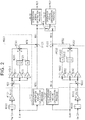
- FIG. 2 illustrates processes to be executed by the first microcomputer 301 and the second microcomputer 302. Each process illustrated in FIG. 2 is implemented such that a program stored in the ROM 34k is executed by the CPU 32k.
- a letter "k" is used.
- An integration process M10k is a process of integrating the rotation angle ⁇ m(k).
- a conversion process M12k is a process of multiplying an output of the integration process M10k by a predetermined coefficient K to convert the output into a rotation angle ⁇ p(k) of the steering shaft.
- the rotation angle ⁇ p(k) is "0" at a neutral position, and its sign varies depending on whether the turn is a right turn or a left turn.
- a feedback operation amount calculation process M20k is a process of calculating a feedback operation amount MFBk for feeding back the rotation angle ⁇ p(k) to the target angle ⁇ p*.
- the feedback operation amount MFBk is basically the sum of an output value of a proportional element, an output value of an integral element, and an output value of a derivative element.
- a deviation calculation process M22k is a process of calculating a difference between the rotation angle ⁇ p(k) and the target angle ⁇ p*.
- a proportional element M24k is a process of multiplying the difference by a proportional coefficient Kp.
- An integral gain multiplication process M26k is a process of multiplying the difference by an integral gain Ki.
- An integral process M28k is a process of updating and outputting an integrated value of outputs of the integral gain multiplication process M26k.
- the integral gain multiplication process M26k and the integral process M28k constitute the integral element.
- a derivative gain multiplication process M30k is a process of multiplying the difference by a derivative gain Kd.
- a derivative process M32k is a process of calculating a derivative of an output of the derivative gain multiplication process M30k.
- the derivative gain multiplication process M30k and the derivative process M32k constitute the derivative element.
- An addition process M34k is a process of computing the sum of the output values of the proportional element M24k, the integral process M28k, and the derivative process M32k and outputting the sum as the feedback operation amount MFBk.
- a feedforward operation amount calculation process M40k is a process of calculating a feedforward operation amount MFFk for control to achieve the target angle ⁇ p*.
- the feedforward operation amount calculation process M40k is a process of increasing the absolute value of the feedforward operation amount MFFk in a case where the absolute value of the target angle ⁇ p* is large than that in a case where the absolute value of the target angle ⁇ p* is small.
- this process can be implemented such that the CPU 32k map-computes the feedforward operation amount MFFk in a state in which the ROM 34k prestores map data having the target angle ⁇ p* as an input variable and the feedforward operation amount MFFk as an output variable.
- the map data is data showing combinations of discrete values of the input variable and values of the output variable corresponding to the values of the input variable.
- the map computing may be such a process that, when the value of the input variable matches any value of the input variable in the map data, the computing result is a corresponding value of the output variable in the map data and, when there is no match, the computing result is a value obtained by interpolating a plurality of values of the output variable included in the map data.
- An addition process M42k is a process of calculating a k-th operation amount MVk by adding the feedback operation amount MFBk and the feedforward operation amount MFFk.
- the k-th operation amount MVk is a q-axis current command value.
- a first operation signal generation process M441 is a process of calculating and outputting the operation signal MS1 of the first inverter 221 so that a q-axis current flowing through the first stator coil 141 is "1/2" of a first operation amount MV1.
- a selection process M50 is a process of selectively outputting one of the two operation amounts that are the first operation amount MV1 and a second operation amount MV2 to a second operation signal generation process M442.
- the second operation signal generation process M442 is a process of calculating and outputting the operation signal MS2 of the second inverter 222 so that a q-axis current flowing through the second stator coil 142 is "1/2" of the output of the selection process M50 in principle.
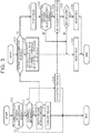
- FIG. 2 are basic processes, but are changed as appropriate by executing processes illustrated in FIG. 3 .
- a left part of FIG. 3 illustrates processes to be implemented such that a program stored in a ROM 341 is repeatedly executed by a CPU 321 in, for example, a predetermined period.
- a right part of FIG. 3 illustrates processes to be implemented such that a program stored in a ROM 342 is repeatedly executed by a CPU 322 in, for example, a predetermined period.
- the processes of FIG. 3 are described below assuming several situations.
- the CPU 321 first determines whether communication between the first microcomputer 301 and the second microcomputer 302 is normal (S10). For example, predetermined data may periodically be exchanged between the first microcomputer 301 and the second microcomputer 302 via the communication line 42, and determination may be made that an abnormality occurs when the data cannot be exchanged.
- the CPU 321 determines whether the first microcomputer 301 cannot control the current flowing through the first stator coil 141 by operating the first inverter 221 (S12). For example, the CPU 321 determines that the control is impossible when an abnormality occurs in a first angle sensor 401 or when the temperature of the first stator coil 141 or the first inverter 221 is equal to or higher than a predefined temperature. For example, determination may be made that an abnormality occurs in the first angle sensor 401 when an output signal from the first angle sensor 401 is fixed to a ground potential or a terminal potential of the battery 52. For example, whether the temperature of the first stator coil 141 or the first inverter 221 is equal to or higher than the predefined temperature may be determined based on histories of currents iu(1), iv(1), and iw(1).
- the CPU 321 determines that the current flowing through the first stator coil 141 can be controlled (S12: NO)
- the CPU 321 outputs the first operation amount MV1 to the second microcomputer 302 via the communication line 42 (S14).
- the CPU 321 completes the process of S14, the CPU 321 temporarily terminates the series of processes illustrated in the left part of FIG. 3 .
- the CPU 322 determines whether the first microcomputer 301 stops controlling the current flowing through the first stator coil 141 (S20).
- the CPU 322 stops an integral process M282 (S22).
- a value held in the integral process M282 is fixed to an initial value "0".
- a feedback operation amount MFB2 is the sum of an output value of a proportional element M242 and an output value of a derivative process M322
- the second operation amount MV2 is the sum of the feedback operation amount MFB2 and a feedforward operation amount MFF2.
- the CPU 322 determines whether the communication between the first microcomputer 301 and the second microcomputer 302 is normal (S24). When the CPU 322 determines that the communication is normal (S24: YES), the CPU 322 acquires the first operation amount MV1 output through the process of S14 in the left part of FIG. 3 (S26). The CPU 322 determines whether the absolute value of a difference between the first operation amount MV1 and the second operation amount MV2 is smaller than a defined value Mth (S28). This process is a process of determining whether the control on the rotation angle ⁇ p(k) toward the target angle ⁇ p* is performed properly. That is, the difference between the first operation amount MV1 and the second operation amount MV2 is expected to be a difference between feedback operation amounts MFB1 and MFB2, and this difference may be infinitesimal.
- the first reason why the difference occurs between the feedback operation amounts MFB1 and MFB2 is that the output value of the integral process M282 is "0".
- An output value of an integral process M281 compensates a deviation in the control using the feedforward operation amount MFF1, and therefore the absolute value is not extremely large.
- the second reason why the difference occurs between the feedback operation amounts MFB1 and MFB2 is a difference between proportional elements M241 and M242 and a difference between derivative processes M321 and M322 due to a difference between a rotation angle ⁇ m(1) detected by the first angle sensor 401 and a rotation angle ⁇ m(2) detected by a second angle sensor 402.
- the control may be performed properly. Therefore, the first operation amount MV1 is selected in the selection process M50 (S30). Thus, the operation signal MS2 for operating the second inverter 222 is generated and output so that the q-axis current flowing through the second stator coil 142 is "1/2" of the first operation amount MV1 through the second operation signal generation process M442.
- the CPU 322 completes the process of S30, the CPU 322 temporarily terminates the series of processes illustrated in the right part of FIG. 3 .
- the CPU 321 determines that the result of the process of S12 is "YES" as illustrated in the left part of FIG. 3 , the CPU 321 notifies the second microcomputer 302 via the communication line 42 that the first microcomputer 301 cannot perform the control (S16).
- the CPU 321 switches relays 241 and 261 to open states through the peripheral circuit 361 or the like (S18).
- the CPU 321 temporarily terminates the series of processes illustrated in the left part of FIG. 3 .
- the CPU 322 determines that the first microcomputer 301 stops controlling the current flowing through the first stator coil 141 (S20: YES), and executes the process of calculating the second operation amount MV2 based on an integral element (I-term) by operating the integral process M282 (S32). Specifically, the CPU 322 sets an initial value of the integral process M282 to a value obtained by subtracting a previous value of the second operation amount MV2 from a previous value of the first operation amount MV1.
- the initial value is set as a previous value, and a value obtained by adding, to the previous value, a value obtained by multiplying together the integral gain Ki and a value obtained by subtracting a current value of a rotation angle ⁇ p(2) from a current value of the target angle ⁇ p* is used for calculating an initial second operation amount MV2 to be used for operating the second inverter 222.
- the CPU 322 selects the second operation amount MV2 in the selection process M50 (S34).
- the operation signal MS2 for operating the second inverter 222 is generated and output so that the q-axis current flowing through the second stator coil 142 is the second operation amount MV2 through the second operation signal generation process M442. Since the first stator coil 141 is not energized, it is necessary that the q-axis current flowing through the second stator coil 142 be set to the second operation amount MV2 to control the rotation angle ⁇ p(2) toward the target angle ⁇ p*.
- the CPU 322 completes the process of S34, the CPU 322 temporarily terminates the series of processes illustrated in the right part of FIG. 3 .
- the CPU 321 determines that an abnormality occurs in the communication between the microcomputers as illustrated in the left part of FIG. 3 (S10: NO)
- the CPU 321 temporarily terminates the series of processes illustrated in the left part of FIG. 3 .
- the CPU 322 determines that the result is "NO" in the process of S24 illustrated in the right part of FIG. 3 , and proceeds to the process of S34.
- the operation signal MS2 for operating the second inverter 222 is generated and output so that the q-axis current flowing through the second stator coil 142 is "1/2" of the second operation amount MV2 through the second operation signal generation process M442.
- the CPU 321 calculates the first operation amount MV1 for controlling the rotation angle ⁇ p(1) toward the target angle ⁇ p*, and operates the first inverter 221 so that the q-axis current flowing through the first stator coil 141 is "1/2" of the first operation amount MV1.
- the CPU 322 operates the second inverter 222 so that the q-axis current flowing through the second stator coil 142 is "1/2" of the first operation amount MV1. Therefore, interference with the control on the steered angle of each steered wheel can be suppressed as compared to a case where the q-axis current flowing through the second stator coil 142 is the second operation amount MV2 when the integral process M282 is operated.
- a difference may occur between the rotation angle ⁇ m(1) detected by the first angle sensor 401 and the rotation angle ⁇ m(2) detected by the second angle sensor 402. If the difference occurs, the output value of the integral process M281 performed by the CPU 321 is a value for eliminating a steady-state deviation between the rotation angle ⁇ p(1) and the target angle ⁇ p*, and the output value of the integral process M282 performed by the CPU 322 is a value for eliminating a steady-state deviation between the rotation angle ⁇ p(2) and the target angle ⁇ p*. Therefore, interference may occur in the control.
- the first microcomputer 301 stops controlling the current flowing through the first stator coil 141.
- the CPU 322 performs control so that the q-axis current flowing through the second stator coil 142 is the second operation amount MV2.
- the integral process M282 is stopped before the control using the first operation amount MV1 is switched to the control using the second operation amount MV2.
- the output value of the integral process M281 may be a value for eliminating the steady-state deviation between the rotation angle ⁇ p(1) and the target angle ⁇ p*.
- the initial value of the integral process M282 is set to the difference between the first operation amount MV1 and the second operation amount MV2 along with the switching.
- the difference between the first operation amount MV1 and the second operation amount MV2 may be a value corresponding to the output value of the integral process M281. Therefore, the initial value of the integral process M282 can be set to the value corresponding to the output value of the integral process M281 immediately before the switching. Thus, it is possible to suppress an abrupt change in the torque of the motor 10 along with the switching.
- the CPU 322 detects the abnormality based on the fact that the absolute value of the difference between the first operation amount MV1 and the second operation amount MV2 is equal to or larger than the defined value Mth. In this case, the CPU 322 uses the second operation amount MV2 for operating the second inverter 222. Thus, contribution of the first operation amount MV1 to the control toward the target angle ⁇ p* can be reduced as compared to a case where the first operation amount MV1 is used for operating the second inverter 222 even though the abnormality occurs in the first operation amount MV1. In this case, the CPU 322 calculates the second operation amount MV2 while stopping the integral process M282. Thus, it is possible to avoid the interference with the control due to the case where the output values of the integral processes M281 and M282 are values for eliminating different steady-state deviations.
- the CPU 322 uses the second operation amount MV2 for operating the second inverter 222. Control is performed so that the q-axis current in the first stator coil 141 is " 1/2" of the first operation amount MV1 and the q-axis current in the second stator coil 142 is "1/2" of the second operation amount MV2. Thus, the torque of the motor 10 can be set to a value appropriate to the control toward the target angle ⁇ p*. In this case, the CPU 322 calculates the second operation amount MV2 while stopping the integral process M282. Thus, it is possible to avoid the interference with the control due to the case where the output values of the integral processes M281 and M282 are values for eliminating different steady-state deviations.
- a k-th drive circuit corresponds to the k-th inverter 22k
- a k-th processing circuit corresponds to the k-th microcomputer 30k
- a k-th operation amount calculation process corresponds to the feedback operation amount calculation process M20k, the feedforward operation amount calculation process M40k, and the addition process M42k.
- An output process corresponds to the process of S14.
- a first use operation process corresponds to the second operation signal generation process M442 when the process of S30 is performed.
- a second use operation process corresponds to the second operation signal generation process M442 when the process of S34 is performed.
- An initial value setting process corresponds to the process of S32.
- An integral element corresponds to the integral gain multiplication process M26k and the integral process M28k, corresponds to the process when the result of determination is "YES" in the process of S20, corresponds to the process when the result of determination is "NO" in the process of S28, and corresponds to the process when the result of determination is "NO” in the process of S24.
- At least one of the matters described in the embodiment may be modified as follows.
- the value obtained by subtracting the previous value of the second operation amount MV2 from the previous value of the first operation amount MV1 be set as the previous value of the integral process M282. That is, it is not essential that the value obtained by adding, to the previous value, the value obtained by multiplying together the integral gain Ki and the value obtained by subtracting the current value of the rotation angle ⁇ p(2) from the current value of the target angle ⁇ p* be set as a current value of the integral process M282 to calculate the initial second operation amount MV2 to be used for operating the second inverter 222.
- the value obtained by subtracting the previous value of the second operation amount MV2 from the previous value of the first operation amount MV1 may be set as the current value of the integral process M282 to calculate a current value of the second operation amount MV2.
- the initial value of the integral process M282 be calculated based on the difference between the first operation amount MV1 and the second operation amount MV2.
- output values of the integral process M281 may sequentially be transmitted from the first microcomputer 301 to the second microcomputer 302 via the communication line 42, and an output value last received by the second microcomputer 302 may be set as the initial value of the integral process M282.
- the integral element may be such a process that the output value of the integral process M28k be multiplied by the integral gain Ki in the integral gain multiplication process M26k.
- the feedback operation amount MFBk is not limited to the sum of the output values of the proportional element M24k, the integral element, and the derivative element.
- the feedback operation amount MFBk may be the sum of two output values of the proportional element and the integral element, the sum of two output values of the integral element and the derivative element, or the output value of the integral element.
- the feedforward operation amount MFFk need not essentially be calculated based on the convertible angle (such as the target angle ⁇ p*) alone.
- the feedforward operation amount MFFk may be set variable depending on a vehicle speed. For example, a value obtained by multiplying a second time derivative of the convertible angle by a proportional coefficient may be added.
- the convertible angle is the angle of the steering shaft, but is not limited to the angle of the steering shaft.
- the convertible angle may be a steered angle that is a tire turning angle.
- the ROM is exemplified as a program storage that constitutes the processing circuit, but the type of the ROM is not described above.
- the ROM may be a non-rewritable memory or an electrically rewritable non-volatile memory.
- the program storage is not limited to the ROM.
- the processing circuit is not limited to a software processing circuit including a program storage that stores a program and a CPU that executes the program.
- the processing circuit may be a dedicated hardware circuit such as an application-specific integrated circuit (ASIC) that executes predetermined processes.
- ASIC application-specific integrated circuit
- the processing circuit is not limited to one of the software processing circuit and the dedicated hardware circuit. A subset of the processes described above may be executed by the software processing circuit, and the remaining processes may be executed by the dedicated hardware circuit.
- the controller is exemplified by the apparatus including the two systems that are the first and second systems, but is not limited to this apparatus.
- the controller may further include a third system. Therefore, the controller may include three or more stator coils, three or more drive circuits, and three or more processing circuits. In this case, it is desirable that one system be set as a main system and the remaining systems be set as subordinate systems.
- the motor is not limited to the SPMSM, but may be an interior permanent magnet synchronous motor (IPMSM).
- IPMSM interior permanent magnet synchronous motor
- the k-th operation amount MVk be a torque command value and the torque command value be converted into a d-axis current command value and a q-axis current command value in the k-th operation signal generation process M44k.
- the motor is not limited to the synchronous motor, but may be an induction machine.
- the motor is not limited to a brushless motor, but may be a brushed direct-current motor.
- the drive circuit is exemplified by the three-phase inverter, but is not limited to the three-phase inverter.
- an H bridge circuit may be used as the drive circuit.
- an H bridge circuit may be used as the drive circuit.
- the relay 241 need not essentially be turned OFF even if the relay 261 is turned OFF.
Landscapes
- Engineering & Computer Science (AREA)
- Power Engineering (AREA)
- Chemical & Material Sciences (AREA)
- Combustion & Propulsion (AREA)
- Transportation (AREA)
- Mechanical Engineering (AREA)
- Control Of Ac Motors In General (AREA)
- Control Of Electric Motors In General (AREA)
- Steering Control In Accordance With Driving Conditions (AREA)
- Power Steering Mechanism (AREA)
Abstract
A controller (20) for a motor (10) includes a first processing circuit (301) and a second processing circuit (302). The first processing circuit (301) is configured to execute a first operation amount calculation process, an operation process, and an output process. The first operation amount calculation process is a process of calculating a first operation amount. The operation process is a process of operating a first drive circuit (221). The second processing circuit (302) is configured to execute a second operation amount calculation process, a first use operation process, a second use operation process, and an initial value setting process. The second operation amount calculation process is a process of calculating a second operation amount. The initial value setting process is a process of setting an initial value of an integral element depending on a value of an integral element of the first operation amount calculation process.
Description
- The present invention relates to a controller configured to control a motor that turns steered wheels and includes a first stator coil and a second stator coil insulated from each other. The controller for the motor is configured to operate a first drive circuit connected to the first stator coil and a second drive circuit connected to the second stator coil.
- For example, Japanese Unexamined Patent Application Publication No.
2018-24335 - The inventors have conducted research on the redundant controller in that the steered angle of each steered wheel is detected by the rotation angle sensors and detection values are fed back to a target value. In this case, the controllability of the steered angle may decrease due to a difference between the detection values from the rotation angle sensors.
- According to the present invention, the decrease in the controllability of the steered angle can be suppressed even if the difference occurs between the detection values from the rotation angle sensors.
- An aspect of the present invention relates to a controller for a motor. The motor is configured to turn a steered wheel and includes a first stator coil and a second stator coil insulated from each other. The controller is configured to operate a first drive circuit connected to the first stator coil and a second drive circuit connected to the second stator coil. The controller includes a first processing circuit and a second processing circuit configured to communicate with each other. The first processing circuit is configured to execute a first operation amount calculation process, an operation process, and an output process. The first operation amount calculation process is a process of calculating a first operation amount based on an output value of an integral element depending on a difference between a target angle and a convertible angle that is based on a detection value from a first angle sensor. The convertible angle is an angle convertible into a steered angle of the steered wheel. The operation process is a process of operating the first drive circuit based on the first operation amount. The output process is a process of outputting the first operation amount to the second processing circuit. The second processing circuit is configured to execute a second operation amount calculation process, a first use operation process, a second use operation process, and an initial value setting process. The second operation amount calculation process is a process of calculating a second operation amount based on an output value of an integral element depending on a difference between the target angle and a convertible angle that is based on a detection value from a second angle sensor. The first use operation process is a process of operating the second drive circuit based on the first operation amount. The second use operation process is a process of operating the second drive circuit based on the second operation amount. The initial value setting process is a process of setting, depending on a value of the integral element of the first operation amount calculation process, an initial value of the integral element to be used for calculating the second operation amount along with switching from the first use operation process to the second use operation process.
- In the configuration described above, the second processing circuit operates the second drive circuit based on the first operation amount in the first use operation process. Therefore, both the first drive circuit and the second drive circuit are operated by the operation amount for feeding back, to the target angle, the convertible angle that is based on the detection value from the first angle sensor. Thus, a decrease in the controllability of the steered angle can be suppressed even if a difference occurs between the detection value from the first angle sensor and the detection value from the second angle sensor.
- Since the first operation amount is calculated by using the integral element in the first operation amount calculation process, the first operation amount is a value for eliminating a steady-state deviation between the target angle and the convertible angle that is based on the first angle sensor. When the second operation amount is used by switching the first use operation process to the second use operation process, a torque of the motor may abruptly change depending on the output value of the integral element of the second operation amount calculation process. In the configuration described above, the initial value of the integral element to be used for calculating the second operation amount is set depending on the value of the integral element of the first operation amount calculation process. Thus, it is possible to suppress the abrupt change in the torque of the motor when the first use operation process is switched to the second use operation process.
- In the controller described above, the second operation amount calculation process may include a process of calculating, when the first use operation process is performed, the second operation amount independently of the integral element to be used for calculating the second operation amount. The initial value setting process may include a process of setting the initial value depending on a difference between the first operation amount and the second operation amount along with the switching from the first use operation process to the second use operation process.
- In the configuration described above, when the first use operation process is performed, the integral element is stopped in the second operation amount calculation process. When the first use operation process is switched to the second use operation process, the difference between the second operation amount and the first operation amount corresponds to the integral element of the first operation amount calculation process. In the configuration described above, the initial value is set depending on the difference between the first operation amount and the second operation amount. Thus, it is possible to suppress the abrupt change in the torque of the motor when the first use operation process is switched to the second use operation process.
- In the controller described above, the second processing circuit may be configured to execute a process of switching the first use operation process to the second use operation process when an abnormality occurs such that the first processing circuit stops operating the first drive circuit. The second operation amount calculation process may include a process of calculating the second operation amount by using the integral element when the first use operation process is switched to the second use operation process based on the abnormality occurring such that the first processing circuit stops operating the first drive circuit.
- If the first processing circuit stops operating the first drive circuit, the first operation amount is not reflected in the control on the motor. When the second operation amount is calculated independently of the integral element, it is difficult to reduce the steady-state deviation between the convertible angle and the target angle. In the configuration described above, if the first processing circuit stops operating the first drive circuit, the second operation amount is calculated based on the integral element. Thus, it is possible to reduce the steady-state deviation between the target angle and the convertible angle that is based on the second angle sensor.
- In the controller described above, the second processing circuit may be configured to execute a process of switching the first use operation process to the second use operation process when an absolute value of a difference between the first operation amount and the second operation amount is equal to or larger than a defined value while the first use operation process is performed. The second operation amount calculation process may include a process of calculating the second operation amount independently of the integral element when the first use operation process is performed. The second operation amount calculation process may include a process of calculating the second operation amount independently of the integral element to be used for calculating the second operation amount when the first use operation process is switched to the second use operation process based on a fact that the absolute value of the difference between the first operation amount and the second operation amount is equal to or larger than the defined value.
- In the configuration described above, the second operation amount is calculated even if the second drive circuit is operated based on the first operation amount. Therefore, the appropriateness of the control using the first operation amount can be evaluated based on comparison between the first operation amount and the second operation amount. In the configuration described above, when determination is made that the appropriateness is low, the second drive circuit is operated based on the second operation amount. In this case, the second operation amount is calculated independently of the integral element. Thus, even if a difference occurs between the detection value from the first angle sensor and the detection value from the second angle sensor, it is possible to avoid interference between the control for reducing, by using the integral element, the steady-state deviation between the target angle and the convertible angle that is based on the detection value from the first angle sensor and the control for reducing, by using the integral element, the steady-state deviation between the target angle and the convertible angle that is based on the detection value from the second angle sensor.
- In the controller described above, the second processing circuit may be configured to execute a process of switching the first use operation process to the second use operation process when an abnormality occurs in communication between the first processing circuit and the second processing circuit. The second operation amount calculation process may include a process of calculating the second operation amount independently of the integral element to be used for calculating the second operation amount when the first use operation process is switched to the second use operation process based on the abnormality occurring in the communication.
- In the configuration described above, if the first operation amount cannot be acquired due to an abnormality in the communication, the second processing circuit operates the second drive circuit based on the second operation amount. Thus, the second drive circuit can be operated even if the first operation amount cannot be acquired. Moreover, the second operation amount is calculated independently of the integral element. Thus, even if a difference occurs between the detection value from the first angle sensor and the detection value from the second angle sensor, it is possible to avoid interference between the control for reducing, by using the integral element, the steady-state deviation between the target angle and the convertible angle that is based on the detection value from the first angle sensor and the control for reducing, by using the integral element, the steady-state deviation between the target angle and the convertible angle that is based on the detection value from the second angle sensor.
- In the controller described above, the second operation amount calculation process may be a process of calculating the second operation amount based on an operation amount for feed forward controlling the convertible angle to the target angle in addition to an operation amount for feedback controlling the convertible angle to the target angle.
- In the configuration described above, the second operation amount is calculated based on the operation amount for feedforward control. Therefore, the output of the integral element compensates a deviation in the control using the feedforward operation amount. Thus, the deviation between the convertible angle and the target angle can be reduced even if the second operation amount is calculated independently of the integral element as compared to a case where the feedforward operation amount is not used.
- Features, advantages, and technical and industrial significance of exemplary embodiments of the invention will be described below with reference to the accompanying drawings, in which like numerals denote like elements, and wherein:
-
FIG. 1 is a diagram illustrating a controller and a motor according to one embodiment; -
FIG. 2 is a diagram illustrating a part of a process to be executed by the controller according to the embodiment; and -
FIG. 3 is a flowchart illustrating a procedure of the process to be executed by the controller. - A controller for a motor according to one embodiment is described below with reference to the drawings. A
motor 10 illustrated inFIG. 1 is a power source for a steering operation actuator configured to turn steered wheels. In this embodiment, a surface permanent magnet synchronous motor (SPMSM) is exemplified as themotor 10. Themotor 10 includes onerotor 12 and afirst stator coil 141 and asecond stator coil 142 that are a pair of stator coils. Acontroller 20 controls themotor 10, and controls a torque that is a control amount of themotor 10. Thecontroller 20 includes a first-system circuit and a second-system circuit that are different circuits corresponding to thefirst stator coil 141 and thesecond stator coil 142. - Specifically, the
controller 20 includes the following components as the first-system circuit. That is, thecontroller 20 includes afirst inverter 221 and afirst microcomputer 301. Thefirst inverter 221 is connected to thefirst stator coil 141. Thefirst microcomputer 301 controls a current flowing through thefirst stator coil 141 by outputting an operation signal MS1 to thefirst inverter 221. Thecontroller 20 includes the following components as the second-system circuit. That is, thecontroller 20 includes asecond inverter 222 and asecond microcomputer 302. Thesecond inverter 222 is connected to thesecond stator coil 142. Thesecond microcomputer 302 controls a current flowing through thesecond stator coil 142 by outputting an operation signal MS2 to thesecond inverter 222. Thefirst microcomputer 301 and thesecond microcomputer 302 are communicable via acommunication line 42. - When the first system and the second system are described collectively, a letter "k" that may take a value "1" or "2" is used hereinafter to describe, for example, that "a k-th inverter 22k is connected to a k-th stator coil 14k".
- A k-th microcomputer 30k acquires a rotation angle θm(k) of the
rotor 12 that is detected by a k-th angle sensor 40k, and three-phase currents iu(k), iv(k), and iw(k) flowing through the k-th stator coil 14k. For example, the currents iu(k), iv(k), and iw(k) may be detected as voltage drops of shunt resistors connected to legs of the k-th inverter 22k. - The k-th microcomputer 30k includes a central processing unit (CPU) 32k, a read-only memory (ROM) 34k, and a peripheral circuit 36k, which are communicable via a local network 38k. The peripheral circuit 36k includes a power supply circuit, a reset circuit, and a circuit configured to generate a clock signal for defining internal operations based on an external clock signal.
- The
controller 20 is communicable with an external higher-level electronic control unit (ECU) 50 via acommunication line 54. A target angle θp* output from the higher-level ECU 50 is input to thefirst microcomputer 301 and thesecond microcomputer 302. The target angle θp* is a target value of a convertible angle, which is convertible into a steered angle of each steered wheel (tire turning angle). In this embodiment, the target angle θp* is a target value of a rotation angle of a steering shaft. A terminal voltage of a battery 52 is applied to each of the higher-level ECU 50, the k-th microcomputer 30k, and the k-th inverter 22k. Specifically, the voltage of the battery 52 is applied to the k-th microcomputer 30k via a relay 24k. A relay 26k is provided between the k-th inverter 22k and the k-th stator coil 14k. -
FIG. 2 illustrates processes to be executed by thefirst microcomputer 301 and thesecond microcomputer 302. Each process illustrated inFIG. 2 is implemented such that a program stored in the ROM 34k is executed by the CPU 32k. When the processes to be executed by thefirst microcomputer 301 and thesecond microcomputer 302 are described collectively, a letter "k" is used. - An integration process M10k is a process of integrating the rotation angle θm(k). A conversion process M12k is a process of multiplying an output of the integration process M10k by a predetermined coefficient K to convert the output into a rotation angle θp(k) of the steering shaft. The rotation angle θp(k) is "0" at a neutral position, and its sign varies depending on whether the turn is a right turn or a left turn.
- A feedback operation amount calculation process M20k is a process of calculating a feedback operation amount MFBk for feeding back the rotation angle θp(k) to the target angle θp*. In this embodiment, the feedback operation amount MFBk is basically the sum of an output value of a proportional element, an output value of an integral element, and an output value of a derivative element. Specifically, a deviation calculation process M22k is a process of calculating a difference between the rotation angle θp(k) and the target angle θp*. A proportional element M24k is a process of multiplying the difference by a proportional coefficient Kp. An integral gain multiplication process M26k is a process of multiplying the difference by an integral gain Ki. An integral process M28k is a process of updating and outputting an integrated value of outputs of the integral gain multiplication process M26k. The integral gain multiplication process M26k and the integral process M28k constitute the integral element. A derivative gain multiplication process M30k is a process of multiplying the difference by a derivative gain Kd. A derivative process M32k is a process of calculating a derivative of an output of the derivative gain multiplication process M30k. The derivative gain multiplication process M30k and the derivative process M32k constitute the derivative element. An addition process M34k is a process of computing the sum of the output values of the proportional element M24k, the integral process M28k, and the derivative process M32k and outputting the sum as the feedback operation amount MFBk.
- A feedforward operation amount calculation process M40k is a process of calculating a feedforward operation amount MFFk for control to achieve the target angle θp*. Specifically, the feedforward operation amount calculation process M40k is a process of increasing the absolute value of the feedforward operation amount MFFk in a case where the absolute value of the target angle θp* is large than that in a case where the absolute value of the target angle θp* is small. For example, this process can be implemented such that the CPU 32k map-computes the feedforward operation amount MFFk in a state in which the ROM 34k prestores map data having the target angle θp* as an input variable and the feedforward operation amount MFFk as an output variable. The map data is data showing combinations of discrete values of the input variable and values of the output variable corresponding to the values of the input variable. For example, the map computing may be such a process that, when the value of the input variable matches any value of the input variable in the map data, the computing result is a corresponding value of the output variable in the map data and, when there is no match, the computing result is a value obtained by interpolating a plurality of values of the output variable included in the map data.
- An addition process M42k is a process of calculating a k-th operation amount MVk by adding the feedback operation amount MFBk and the feedforward operation amount MFFk. The k-th operation amount MVk is a q-axis current command value.
- A first operation signal generation process M441 is a process of calculating and outputting the operation signal MS1 of the
first inverter 221 so that a q-axis current flowing through thefirst stator coil 141 is "1/2" of a first operation amount MV1. - A selection process M50 is a process of selectively outputting one of the two operation amounts that are the first operation amount MV1 and a second operation amount MV2 to a second operation signal generation process M442.
- The second operation signal generation process M442 is a process of calculating and outputting the operation signal MS2 of the
second inverter 222 so that a q-axis current flowing through thesecond stator coil 142 is "1/2" of the output of the selection process M50 in principle. - In this embodiment, the processes of
FIG. 2 are basic processes, but are changed as appropriate by executing processes illustrated inFIG. 3 . A left part ofFIG. 3 illustrates processes to be implemented such that a program stored in aROM 341 is repeatedly executed by aCPU 321 in, for example, a predetermined period. A right part ofFIG. 3 illustrates processes to be implemented such that a program stored in aROM 342 is repeatedly executed by aCPU 322 in, for example, a predetermined period. The processes ofFIG. 3 are described below assuming several situations. - In the series of processes illustrated in the left part of
FIG. 3 , theCPU 321 first determines whether communication between thefirst microcomputer 301 and thesecond microcomputer 302 is normal (S10). For example, predetermined data may periodically be exchanged between thefirst microcomputer 301 and thesecond microcomputer 302 via thecommunication line 42, and determination may be made that an abnormality occurs when the data cannot be exchanged. - When the
CPU 321 determines that the communication is normal (S10: YES), theCPU 321 determines whether thefirst microcomputer 301 cannot control the current flowing through thefirst stator coil 141 by operating the first inverter 221 (S12). For example, theCPU 321 determines that the control is impossible when an abnormality occurs in afirst angle sensor 401 or when the temperature of thefirst stator coil 141 or thefirst inverter 221 is equal to or higher than a predefined temperature. For example, determination may be made that an abnormality occurs in thefirst angle sensor 401 when an output signal from thefirst angle sensor 401 is fixed to a ground potential or a terminal potential of the battery 52. For example, whether the temperature of thefirst stator coil 141 or thefirst inverter 221 is equal to or higher than the predefined temperature may be determined based on histories of currents iu(1), iv(1), and iw(1). - When the
CPU 321 determines that the current flowing through thefirst stator coil 141 can be controlled (S12: NO), theCPU 321 outputs the first operation amount MV1 to thesecond microcomputer 302 via the communication line 42 (S14). When theCPU 321 completes the process of S14, theCPU 321 temporarily terminates the series of processes illustrated in the left part ofFIG. 3 . - As illustrated in the right part of
FIG. 3 , theCPU 322 determines whether thefirst microcomputer 301 stops controlling the current flowing through the first stator coil 141 (S20). When thefirst microcomputer 301 is operating (S20: NO), theCPU 322 stops an integral process M282 (S22). Specifically, a value held in the integral process M282 is fixed to an initial value "0". Thus, a feedback operation amount MFB2 is the sum of an output value of a proportional element M242 and an output value of a derivative process M322, and the second operation amount MV2 is the sum of the feedback operation amount MFB2 and a feedforward operation amount MFF2. - The
CPU 322 determines whether the communication between thefirst microcomputer 301 and thesecond microcomputer 302 is normal (S24). When theCPU 322 determines that the communication is normal (S24: YES), theCPU 322 acquires the first operation amount MV1 output through the process of S14 in the left part ofFIG. 3 (S26). TheCPU 322 determines whether the absolute value of a difference between the first operation amount MV1 and the second operation amount MV2 is smaller than a defined value Mth (S28). This process is a process of determining whether the control on the rotation angle θp(k) toward the target angle θp* is performed properly. That is, the difference between the first operation amount MV1 and the second operation amount MV2 is expected to be a difference between feedback operation amounts MFB1 and MFB2, and this difference may be infinitesimal. - That is, the first reason why the difference occurs between the feedback operation amounts MFB1 and MFB2 is that the output value of the integral process M282 is "0". An output value of an integral process M281 compensates a deviation in the control using the feedforward operation amount MFF1, and therefore the absolute value is not extremely large. The second reason why the difference occurs between the feedback operation amounts MFB1 and MFB2 is a difference between proportional elements M241 and M242 and a difference between derivative processes M321 and M322 due to a difference between a rotation angle θm(1) detected by the
first angle sensor 401 and a rotation angle θm(2) detected by asecond angle sensor 402. Since the absolute value of the difference between the rotation angles θm(1) and θm(2) is infinitesimal, the absolute value of the difference between the proportional elements M241 and M242 and the absolute value of the difference between the derivative processes M321 and M322 are also small. - When the
CPU 322 determines that the absolute value is smaller than the defined value Mth (S28: YES), the control may be performed properly. Therefore, the first operation amount MV1 is selected in the selection process M50 (S30). Thus, the operation signal MS2 for operating thesecond inverter 222 is generated and output so that the q-axis current flowing through thesecond stator coil 142 is "1/2" of the first operation amount MV1 through the second operation signal generation process M442. When theCPU 322 completes the process of S30, theCPU 322 temporarily terminates the series of processes illustrated in the right part ofFIG. 3 . - When the
CPU 321 determines that the result of the process of S12 is "YES" as illustrated in the left part ofFIG. 3 , theCPU 321 notifies thesecond microcomputer 302 via thecommunication line 42 that thefirst microcomputer 301 cannot perform the control (S16). TheCPU 321 switches relays 241 and 261 to open states through the peripheral circuit 361 or the like (S18). When theCPU 321 completes the process of S18, theCPU 321 temporarily terminates the series of processes illustrated in the left part ofFIG. 3 . - In this case, as illustrated in the right part of
FIG. 3 , theCPU 322 determines that thefirst microcomputer 301 stops controlling the current flowing through the first stator coil 141 (S20: YES), and executes the process of calculating the second operation amount MV2 based on an integral element (I-term) by operating the integral process M282 (S32). Specifically, theCPU 322 sets an initial value of the integral process M282 to a value obtained by subtracting a previous value of the second operation amount MV2 from a previous value of the first operation amount MV1. The initial value is set as a previous value, and a value obtained by adding, to the previous value, a value obtained by multiplying together the integral gain Ki and a value obtained by subtracting a current value of a rotation angle θp(2) from a current value of the target angle θp* is used for calculating an initial second operation amount MV2 to be used for operating thesecond inverter 222. - The
CPU 322 selects the second operation amount MV2 in the selection process M50 (S34). In this case, the operation signal MS2 for operating thesecond inverter 222 is generated and output so that the q-axis current flowing through thesecond stator coil 142 is the second operation amount MV2 through the second operation signal generation process M442. Since thefirst stator coil 141 is not energized, it is necessary that the q-axis current flowing through thesecond stator coil 142 be set to the second operation amount MV2 to control the rotation angle θp(2) toward the target angle θp*. When theCPU 322 completes the process of S34, theCPU 322 temporarily terminates the series of processes illustrated in the right part ofFIG. 3 . - In this case, it is assumed that the process of S14 in the left part of
FIG. 3 is performed. In this case, theCPU 322 determines that the result is "NO" in the process of S28 illustrated in the right part ofFIG. 3 , and proceeds to the process of S34. Thus, the operation signal MS2 for operating thesecond inverter 222 is generated and output so that the q-axis current flowing through thesecond stator coil 142 is "1/2" of the second operation amount MV2 through the second operation signal generation process M442. - When the
CPU 321 determines that an abnormality occurs in the communication between the microcomputers as illustrated in the left part ofFIG. 3 (S10: NO), theCPU 321 temporarily terminates the series of processes illustrated in the left part ofFIG. 3 . - In this case, the
CPU 322 determines that the result is "NO" in the process of S24 illustrated in the right part ofFIG. 3 , and proceeds to the process of S34. Thus, the operation signal MS2 for operating thesecond inverter 222 is generated and output so that the q-axis current flowing through thesecond stator coil 142 is "1/2" of the second operation amount MV2 through the second operation signal generation process M442. - Actions and effects of this embodiment are described. The
CPU 321 calculates the first operation amount MV1 for controlling the rotation angle θp(1) toward the target angle θp*, and operates thefirst inverter 221 so that the q-axis current flowing through thefirst stator coil 141 is "1/2" of the first operation amount MV1. TheCPU 322 operates thesecond inverter 222 so that the q-axis current flowing through thesecond stator coil 142 is "1/2" of the first operation amount MV1. Therefore, interference with the control on the steered angle of each steered wheel can be suppressed as compared to a case where the q-axis current flowing through thesecond stator coil 142 is the second operation amount MV2 when the integral process M282 is operated. A difference may occur between the rotation angle θm(1) detected by thefirst angle sensor 401 and the rotation angle θm(2) detected by thesecond angle sensor 402. If the difference occurs, the output value of the integral process M281 performed by theCPU 321 is a value for eliminating a steady-state deviation between the rotation angle θp(1) and the target angle θp*, and the output value of the integral process M282 performed by theCPU 322 is a value for eliminating a steady-state deviation between the rotation angle θp(2) and the target angle θp*. Therefore, interference may occur in the control. - If the
first microcomputer 301 cannot control the q-axis current in thefirst stator coil 141, thefirst microcomputer 301 stops controlling the current flowing through thefirst stator coil 141. In this case, theCPU 322 performs control so that the q-axis current flowing through thesecond stator coil 142 is the second operation amount MV2. The integral process M282 is stopped before the control using the first operation amount MV1 is switched to the control using the second operation amount MV2. Before the switching, the output value of the integral process M281 may be a value for eliminating the steady-state deviation between the rotation angle θp(1) and the target angle θp*. When the second operation amount MV2 is used while starting the operation of the integral process M282, a difference corresponding to the output value of the integral process M281 occurs between the second operation amount MV2 at the time of switching and the first operation amount MV1 immediately before the switching. In this embodiment, the initial value of the integral process M282 is set to the difference between the first operation amount MV1 and the second operation amount MV2 along with the switching. The difference between the first operation amount MV1 and the second operation amount MV2 may be a value corresponding to the output value of the integral process M281. Therefore, the initial value of the integral process M282 can be set to the value corresponding to the output value of the integral process M281 immediately before the switching. Thus, it is possible to suppress an abrupt change in the torque of themotor 10 along with the switching. - If an abnormality occurs in the control but the
first microcomputer 301 cannot identify the cause of the abnormality, theCPU 322 detects the abnormality based on the fact that the absolute value of the difference between the first operation amount MV1 and the second operation amount MV2 is equal to or larger than the defined value Mth. In this case, theCPU 322 uses the second operation amount MV2 for operating thesecond inverter 222. Thus, contribution of the first operation amount MV1 to the control toward the target angle θp* can be reduced as compared to a case where the first operation amount MV1 is used for operating thesecond inverter 222 even though the abnormality occurs in the first operation amount MV1. In this case, theCPU 322 calculates the second operation amount MV2 while stopping the integral process M282. Thus, it is possible to avoid the interference with the control due to the case where the output values of the integral processes M281 and M282 are values for eliminating different steady-state deviations. - If an abnormality occurs in the communication between the
first microcomputer 301 and thesecond microcomputer 302, theCPU 322 uses the second operation amount MV2 for operating thesecond inverter 222. Control is performed so that the q-axis current in thefirst stator coil 141 is " 1/2" of the first operation amount MV1 and the q-axis current in thesecond stator coil 142 is "1/2" of the second operation amount MV2. Thus, the torque of themotor 10 can be set to a value appropriate to the control toward the target angle θp*. In this case, theCPU 322 calculates the second operation amount MV2 while stopping the integral process M282. Thus, it is possible to avoid the interference with the control due to the case where the output values of the integral processes M281 and M282 are values for eliminating different steady-state deviations. - Correspondences between the matters described in the embodiment and the matters described in "SUMMARY OF THE INVENTION" are as follows. Assuming the variable k as "1" or "2", a k-th drive circuit corresponds to the k-th inverter 22k, a k-th processing circuit corresponds to the k-th microcomputer 30k, and a k-th operation amount calculation process corresponds to the feedback operation amount calculation process M20k, the feedforward operation amount calculation process M40k, and the addition process M42k. An output process corresponds to the process of S14. A first use operation process corresponds to the second operation signal generation process M442 when the process of S30 is performed. A second use operation process corresponds to the second operation signal generation process M442 when the process of S34 is performed. An initial value setting process corresponds to the process of S32. An integral element corresponds to the integral gain multiplication process M26k and the integral process M28k, corresponds to the process when the result of determination is "YES" in the process of S20, corresponds to the process when the result of determination is "NO" in the process of S28, and corresponds to the process when the result of determination is "NO" in the process of S24.
- At least one of the matters described in the embodiment may be modified as follows. In the initial value setting process, it is not essential that the value obtained by subtracting the previous value of the second operation amount MV2 from the previous value of the first operation amount MV1 be set as the previous value of the integral process M282. That is, it is not essential that the value obtained by adding, to the previous value, the value obtained by multiplying together the integral gain Ki and the value obtained by subtracting the current value of the rotation angle θp(2) from the current value of the target angle θp* be set as a current value of the integral process M282 to calculate the initial second operation amount MV2 to be used for operating the
second inverter 222. For example, the value obtained by subtracting the previous value of the second operation amount MV2 from the previous value of the first operation amount MV1 may be set as the current value of the integral process M282 to calculate a current value of the second operation amount MV2. - It is not essential that the initial value of the integral process M282 be calculated based on the difference between the first operation amount MV1 and the second operation amount MV2. For example, output values of the integral process M281 may sequentially be transmitted from the
first microcomputer 301 to thesecond microcomputer 302 via thecommunication line 42, and an output value last received by thesecond microcomputer 302 may be set as the initial value of the integral process M282. - For example, if the integral gain Ki is not set variable regarding the feedback operation amount MFBk, the integral element may be such a process that the output value of the integral process M28k be multiplied by the integral gain Ki in the integral gain multiplication process M26k.
- The feedback operation amount MFBk is not limited to the sum of the output values of the proportional element M24k, the integral element, and the derivative element. For example, the feedback operation amount MFBk may be the sum of two output values of the proportional element and the integral element, the sum of two output values of the integral element and the derivative element, or the output value of the integral element.
- The feedforward operation amount MFFk need not essentially be calculated based on the convertible angle (such as the target angle θp*) alone. For example, the feedforward operation amount MFFk may be set variable depending on a vehicle speed. For example, a value obtained by multiplying a second time derivative of the convertible angle by a proportional coefficient may be added.
- It is not essential to calculate the k-th operation amount MVk based on the feedforward operation amount MFFk.
- In the embodiment described above, the convertible angle is the angle of the steering shaft, but is not limited to the angle of the steering shaft. For example, the convertible angle may be a steered angle that is a tire turning angle.
- In the embodiment described above, the ROM is exemplified as a program storage that constitutes the processing circuit, but the type of the ROM is not described above. For example, the ROM may be a non-rewritable memory or an electrically rewritable non-volatile memory. The program storage is not limited to the ROM.
- The processing circuit is not limited to a software processing circuit including a program storage that stores a program and a CPU that executes the program. For example, the processing circuit may be a dedicated hardware circuit such as an application-specific integrated circuit (ASIC) that executes predetermined processes.
- The processing circuit is not limited to one of the software processing circuit and the dedicated hardware circuit. A subset of the processes described above may be executed by the software processing circuit, and the remaining processes may be executed by the dedicated hardware circuit.
- In the embodiment described above, the controller is exemplified by the apparatus including the two systems that are the first and second systems, but is not limited to this apparatus. For example, the controller may further include a third system. Therefore, the controller may include three or more stator coils, three or more drive circuits, and three or more processing circuits. In this case, it is desirable that one system be set as a main system and the remaining systems be set as subordinate systems.
- The motor is not limited to the SPMSM, but may be an interior permanent magnet synchronous motor (IPMSM). In the case of the IPMSM, it is desirable that the k-th operation amount MVk be a torque command value and the torque command value be converted into a d-axis current command value and a q-axis current command value in the k-th operation signal generation process M44k. The motor is not limited to the synchronous motor, but may be an induction machine. The motor is not limited to a brushless motor, but may be a brushed direct-current motor.
- In the embodiment described above, the drive circuit is exemplified by the three-phase inverter, but is not limited to the three-phase inverter. For example, if a direct-current motor is used as the motor, an H bridge circuit may be used as the drive circuit.
- If a direct-current motor is used as the motor, an H bridge circuit may be used as the drive circuit.
- It is not essential to provide the
relays relay 261 in the process of S18. In the process of S18, therelay 241 need not essentially be turned OFF even if therelay 261 is turned OFF.
Claims (6)
- A controller (20) for a motor (10),
the motor (10) being configured to turn a steered wheel and including a first stator coil (141) and a second stator coil (142) insulated from each other,
the controller (20) being configured to operate a first drive circuit (221) connected to the first stator coil (141) and a second drive circuit (222) connected to the second stator coil (142),
the controller (20) characterized by comprising a first processing circuit (301) and a second processing circuit (302) configured to communicate with each other,
the first processing circuit (301) being configured to execute a first operation amount calculation process, an operation process, and an output process,
the first operation amount calculation process being a process of calculating a first operation amount based on an output value of an integral element depending on a difference between a target angle and a convertible angle that is based on a detection value from a first angle sensor, the convertible angle being an angle convertible into a steered angle of the steered wheel,
the operation process being a process of operating the first drive circuit (221) based on the first operation amount,
the output process being a process of outputting the first operation amount to the second processing circuit (302),
the second processing circuit (302) being configured to execute a second operation amount calculation process, a first use operation process, a second use operation process, and an initial value setting process,
the second operation amount calculation process being a process of calculating a second operation amount based on an output value of an integral element depending on a difference between the target angle and a convertible angle that is based on a detection value from a second angle sensor,
the first use operation process being a process of operating the second drive circuit (222) based on the first operation amount,
the second use operation process being a process of operating the second drive circuit (222) based on the second operation amount,
the initial value setting process being a process of setting, depending on a value of the integral element of the first operation amount calculation process, an initial value of the integral element to be used for calculating the second operation amount along with switching from the first use operation process to the second use operation process. - The controller (20) for the motor (10) according to claim 1, characterized in that
the second operation amount calculation process includes a process of calculating, when the first use operation process is performed, the second operation amount independently of the integral element to be used for calculating the second operation amount, and
the initial value setting process includes a process of setting the initial value depending on a difference between the first operation amount and the second operation amount along with the switching from the first use operation process to the second use operation process. - The controller (20) for the motor (10) according to claim 1 or 2, characterized in that
the second processing circuit (302) is configured to execute a process of switching the first use operation process to the second use operation process when an abnormality occurs such that the first processing circuit (301) stops operating the first drive circuit (221), and
the second operation amount calculation process includes a process of calculating the second operation amount by using the integral element when the first use operation process is switched to the second use operation process based on the abnormality occurring such that the first processing circuit (301) stops operating the first drive circuit. - The controller (20) for the motor (10) according to any one of claims 1 to 3, characterized in that
the second processing circuit (302) is configured to execute a process of switching the first use operation process to the second use operation process when an absolute value of a difference between the first operation amount and the second operation amount is equal to or larger than a defined value while the first use operation process is performed,
the second operation amount calculation process includes a process of calculating the second operation amount independently of the integral element when the first use operation process is performed, and
the second operation amount calculation process includes a process of calculating the second operation amount independently of the integral element to be used for calculating the second operation amount when the first use operation process is switched to the second use operation process based on a fact that the absolute value of the difference between the first operation amount and the second operation amount is equal to or larger than the defined value. - The controller (20) for the motor (10) according to any one of claims 1 to 4, characterized in that
the second processing circuit (302) is configured to execute a process of switching the first use operation process to the second use operation process when an abnormality occurs in communication between the first processing circuit (301) and the second processing circuit (302), and
the second operation amount calculation process includes a process of calculating the second operation amount independently of the integral element to be used for calculating the second operation amount when the first use operation process is switched to the second use operation process based on the abnormality occurring in the communication. - The controller (20) for the motor (10) according to claim 4 or 5, characterized in that the second operation amount calculation process is a process of calculating the second operation amount based on an operation amount for feed forward controlling the convertible angle to the target angle in addition to an operation amount for feedback controlling the convertible angle to the target angle.
Applications Claiming Priority (1)
| Application Number | Priority Date | Filing Date | Title |
|---|---|---|---|
| JP2019043676A JP7111033B2 (en) | 2019-03-11 | 2019-03-11 | motor controller |
Publications (1)
| Publication Number | Publication Date |
|---|---|
| EP3709502A1 true EP3709502A1 (en) | 2020-09-16 |
Family
ID=69742788
Family Applications (1)
| Application Number | Title | Priority Date | Filing Date |
|---|---|---|---|
| EP20159826.5A Withdrawn EP3709502A1 (en) | 2019-03-11 | 2020-02-27 | Controller for motor |
Country Status (4)
| Country | Link |
|---|---|
| US (1) | US11095247B2 (en) |
| EP (1) | EP3709502A1 (en) |
| JP (1) | JP7111033B2 (en) |
| CN (1) | CN111674455A (en) |
Families Citing this family (1)
| Publication number | Priority date | Publication date | Assignee | Title |
|---|---|---|---|---|
| US11572095B2 (en) * | 2019-02-28 | 2023-02-07 | Steering Solutions Ip Holding Corporation | Method and system for electronic power steering angle control with non-zero initial condition |
Citations (3)
| Publication number | Priority date | Publication date | Assignee | Title |
|---|---|---|---|---|
| EP3196711A1 (en) * | 2014-08-27 | 2017-07-26 | Hitachi Automotive Systems, Ltd. | Feedback control device and electric power steering device |
| US20170361869A1 (en) * | 2016-06-17 | 2017-12-21 | Steering Solutions Ip Holding Corporation | Electrical power steering with two controllers and closed-loop integral action |
| JP2018024335A (en) | 2016-08-10 | 2018-02-15 | 株式会社ジェイテクト | Motor control device |
Family Cites Families (9)
| Publication number | Priority date | Publication date | Assignee | Title |
|---|---|---|---|---|
| US8791644B2 (en) * | 2005-03-29 | 2014-07-29 | Linear Technology Corporation | Offset correction circuit for voltage-controlled current source |
| JP4527602B2 (en) * | 2005-05-30 | 2010-08-18 | 日立オートモティブシステムズ株式会社 | Method for manufacturing stator coil |
| US7728463B2 (en) * | 2007-02-12 | 2010-06-01 | Rockwell Collins, Inc. | Reluctance laminations for a motor assembly |
| US8466646B2 (en) * | 2008-04-02 | 2013-06-18 | Continental Automotive Systems, Inc. | Apparatus and method for determining angular position |
| JP5125724B2 (en) * | 2008-04-22 | 2013-01-23 | トヨタ自動車株式会社 | Vehicle control device |
| JP5591345B2 (en) * | 2010-10-27 | 2014-09-17 | 三菱電機株式会社 | Electric motor control device |
| JP6848239B2 (en) * | 2016-07-19 | 2021-03-24 | 日本電産株式会社 | Motor control device and electric power steering device |
| JP6701044B2 (en) * | 2016-09-23 | 2020-05-27 | 株式会社ジェイテクト | Motor control device and steering device |
| US12122449B2 (en) * | 2019-09-06 | 2024-10-22 | Sensata Technologies, Inc. | Steer by wire system with redundant angular position sensing and an end-of-travel stop |
-
2019
- 2019-03-11 JP JP2019043676A patent/JP7111033B2/en active Active
-
2020
- 2020-02-25 CN CN202010116536.5A patent/CN111674455A/en active Pending
- 2020-02-26 US US16/801,802 patent/US11095247B2/en active Active
- 2020-02-27 EP EP20159826.5A patent/EP3709502A1/en not_active Withdrawn
Patent Citations (3)
| Publication number | Priority date | Publication date | Assignee | Title |
|---|---|---|---|---|
| EP3196711A1 (en) * | 2014-08-27 | 2017-07-26 | Hitachi Automotive Systems, Ltd. | Feedback control device and electric power steering device |
| US20170361869A1 (en) * | 2016-06-17 | 2017-12-21 | Steering Solutions Ip Holding Corporation | Electrical power steering with two controllers and closed-loop integral action |
| JP2018024335A (en) | 2016-08-10 | 2018-02-15 | 株式会社ジェイテクト | Motor control device |
Non-Patent Citations (1)
| Title |
|---|
| JOHN WILLIAM BENNETT: "Fault Tolerant Electromechanical Actuators for Aircraft", 1 November 2010 (2010-11-01), XP055675084, Retrieved from the Internet <URL:https://pdfs.semanticscholar.org/21dd/65c1dba80fb14b211d9f2b290e7475f5d1d1.pdf?_ga=2.240473540.637559629.1583832198-484601563.1552319601> [retrieved on 20200310] * |
Also Published As
| Publication number | Publication date |
|---|---|
| JP7111033B2 (en) | 2022-08-02 |
| CN111674455A (en) | 2020-09-18 |
| JP2020150583A (en) | 2020-09-17 |
| US20200295698A1 (en) | 2020-09-17 |
| US11095247B2 (en) | 2021-08-17 |
Similar Documents
| Publication | Publication Date | Title |
|---|---|---|
| EP3726726B1 (en) | Control system for motor and control device for motor | |
| EP3709503B1 (en) | Controller for motor | |
| US11251732B2 (en) | Motor control device and motor control method | |
| US10384711B2 (en) | Steering controller | |
| CN106208866B (en) | Motor control anti-windup saturation and voltage saturation design for electric power steering | |
| US11496086B2 (en) | Control device for motor | |
| CN112865651B (en) | Supply current management under motor current control for voltage saturation | |
| US11095247B2 (en) | Controller for motor | |
| JP2019050684A (en) | Control device for power steering device | |
| JP2013159240A (en) | Electric power steering device | |
| US11509250B2 (en) | Control device | |
| JP2010098808A (en) | Motor control device | |
| JP5012157B2 (en) | Electric power steering device | |
| JP5664945B2 (en) | Motor control device | |
| JP2015231786A (en) | Automatic steering device |
Legal Events
| Date | Code | Title | Description |
|---|---|---|---|
| PUAI | Public reference made under article 153(3) epc to a published international application that has entered the european phase |
Free format text: ORIGINAL CODE: 0009012 |
|
| STAA | Information on the status of an ep patent application or granted ep patent |
Free format text: STATUS: THE APPLICATION HAS BEEN PUBLISHED |
|
| AK | Designated contracting states |
Kind code of ref document: A1 Designated state(s): AL AT BE BG CH CY CZ DE DK EE ES FI FR GB GR HR HU IE IS IT LI LT LU LV MC MK MT NL NO PL PT RO RS SE SI SK SM TR |
|
| AX | Request for extension of the european patent |
Extension state: BA ME |
|
| STAA | Information on the status of an ep patent application or granted ep patent |
Free format text: STATUS: THE APPLICATION IS DEEMED TO BE WITHDRAWN |
|
| 18D | Application deemed to be withdrawn |
Effective date: 20210317 |