EP3709500B1 - Estimation of the amplitude of a periodic component in a measured signal through a delta-sigma modulator - Google Patents
Estimation of the amplitude of a periodic component in a measured signal through a delta-sigma modulator Download PDFInfo
- Publication number
- EP3709500B1 EP3709500B1 EP19305291.7A EP19305291A EP3709500B1 EP 3709500 B1 EP3709500 B1 EP 3709500B1 EP 19305291 A EP19305291 A EP 19305291A EP 3709500 B1 EP3709500 B1 EP 3709500B1
- Authority
- EP
- European Patent Office
- Prior art keywords
- signal
- amplitude
- signals
- periodic
- delta
- Prior art date
- Legal status (The legal status is an assumption and is not a legal conclusion. Google has not performed a legal analysis and makes no representation as to the accuracy of the status listed.)
- Active
Links
Images

Classifications
-
- H—ELECTRICITY
- H02—GENERATION; CONVERSION OR DISTRIBUTION OF ELECTRIC POWER
- H02P—CONTROL OR REGULATION OF ELECTRIC MOTORS, ELECTRIC GENERATORS OR DYNAMO-ELECTRIC CONVERTERS; CONTROLLING TRANSFORMERS, REACTORS OR CHOKE COILS
- H02P21/00—Arrangements or methods for the control of electric machines by vector control, e.g. by control of field orientation
- H02P21/14—Estimation or adaptation of machine parameters, e.g. flux, current or voltage
- H02P21/18—Estimation of position or speed
-
- H—ELECTRICITY
- H02—GENERATION; CONVERSION OR DISTRIBUTION OF ELECTRIC POWER
- H02P—CONTROL OR REGULATION OF ELECTRIC MOTORS, ELECTRIC GENERATORS OR DYNAMO-ELECTRIC CONVERTERS; CONTROLLING TRANSFORMERS, REACTORS OR CHOKE COILS
- H02P6/00—Arrangements for controlling synchronous motors or other dynamo-electric motors using electronic commutation dependent on the rotor position; Electronic commutators therefor
- H02P6/14—Electronic commutators
- H02P6/16—Circuit arrangements for detecting position
- H02P6/18—Circuit arrangements for detecting position without separate position detecting elements
-
- H—ELECTRICITY
- H02—GENERATION; CONVERSION OR DISTRIBUTION OF ELECTRIC POWER
- H02P—CONTROL OR REGULATION OF ELECTRIC MOTORS, ELECTRIC GENERATORS OR DYNAMO-ELECTRIC CONVERTERS; CONTROLLING TRANSFORMERS, REACTORS OR CHOKE COILS
- H02P23/00—Arrangements or methods for the control of AC motors characterised by a control method other than vector control
- H02P23/12—Observer control, e.g. using Luenberger observers or Kalman filters
-
- H—ELECTRICITY
- H02—GENERATION; CONVERSION OR DISTRIBUTION OF ELECTRIC POWER
- H02P—CONTROL OR REGULATION OF ELECTRIC MOTORS, ELECTRIC GENERATORS OR DYNAMO-ELECTRIC CONVERTERS; CONTROLLING TRANSFORMERS, REACTORS OR CHOKE COILS
- H02P21/00—Arrangements or methods for the control of electric machines by vector control, e.g. by control of field orientation
- H02P21/14—Estimation or adaptation of machine parameters, e.g. flux, current or voltage
-
- H—ELECTRICITY
- H02—GENERATION; CONVERSION OR DISTRIBUTION OF ELECTRIC POWER
- H02P—CONTROL OR REGULATION OF ELECTRIC MOTORS, ELECTRIC GENERATORS OR DYNAMO-ELECTRIC CONVERTERS; CONTROLLING TRANSFORMERS, REACTORS OR CHOKE COILS
- H02P21/00—Arrangements or methods for the control of electric machines by vector control, e.g. by control of field orientation
- H02P21/24—Vector control not involving the use of rotor position or rotor speed sensors
- H02P21/28—Stator flux based control
-
- H—ELECTRICITY
- H02—GENERATION; CONVERSION OR DISTRIBUTION OF ELECTRIC POWER
- H02P—CONTROL OR REGULATION OF ELECTRIC MOTORS, ELECTRIC GENERATORS OR DYNAMO-ELECTRIC CONVERTERS; CONTROLLING TRANSFORMERS, REACTORS OR CHOKE COILS
- H02P23/00—Arrangements or methods for the control of AC motors characterised by a control method other than vector control
- H02P23/14—Estimation or adaptation of motor parameters, e.g. rotor time constant, flux, speed, current or voltage
-
- H—ELECTRICITY
- H03—ELECTRONIC CIRCUITRY
- H03H—IMPEDANCE NETWORKS, e.g. RESONANT CIRCUITS; RESONATORS
- H03H17/00—Networks using digital techniques
- H03H17/02—Frequency selective networks
- H03H17/06—Non-recursive filters
- H03H17/0621—Non-recursive filters with input-sampling frequency and output-delivery frequency which differ, e.g. extrapolation; Anti-aliasing
- H03H17/0635—Non-recursive filters with input-sampling frequency and output-delivery frequency which differ, e.g. extrapolation; Anti-aliasing characterized by the ratio between the input-sampling and output-delivery frequencies
- H03H17/065—Non-recursive filters with input-sampling frequency and output-delivery frequency which differ, e.g. extrapolation; Anti-aliasing characterized by the ratio between the input-sampling and output-delivery frequencies the ratio being integer
- H03H17/0664—Non-recursive filters with input-sampling frequency and output-delivery frequency which differ, e.g. extrapolation; Anti-aliasing characterized by the ratio between the input-sampling and output-delivery frequencies the ratio being integer where the output-delivery frequency is lower than the input sampling frequency, i.e. decimation
-
- H—ELECTRICITY
- H02—GENERATION; CONVERSION OR DISTRIBUTION OF ELECTRIC POWER
- H02P—CONTROL OR REGULATION OF ELECTRIC MOTORS, ELECTRIC GENERATORS OR DYNAMO-ELECTRIC CONVERTERS; CONTROLLING TRANSFORMERS, REACTORS OR CHOKE COILS
- H02P2203/00—Indexing scheme relating to controlling arrangements characterised by the means for detecting the position of the rotor
- H02P2203/11—Determination or estimation of the rotor position or other motor parameters based on the analysis of high-frequency signals
-
- H—ELECTRICITY
- H03—ELECTRONIC CIRCUITRY
- H03H—IMPEDANCE NETWORKS, e.g. RESONANT CIRCUITS; RESONATORS
- H03H17/00—Networks using digital techniques
- H03H2017/0072—Theoretical filter design
- H03H2017/0081—Theoretical filter design of FIR filters
Definitions
- the invention concerns signal processing, in particular while not exclusively, in the context of control of devices. More particularly, the invention may be used in the context of sensorless control of electrical motors.
- sensorless does not refer to the complete absence of sensors but to the absence of some sensors, such as rotor speed or position sensors. It however generally relies on measurements of motor currents (or potentially of motor voltages).
- Sensorless control of devices may rely on extraction of information through signal injection, based on a measured variable (such as the current values).
- High-frequency signal injection consists in superimposing a high-frequency signal to the control signals of electric motors.
- the measured current response of the motor to this supplementary excitation is then extracted from the current measurement and additional signal processing allows to retrieve the speed or the position of the rotor at low or even zero speed.
- the unknown signals y i can then be used to estimate the position of the rotor or its speed, so as to determine the control signal to be applied to the motor.
- the desired frequency can be obtained by band-pass filtering of the signal y(t) and by using an arctangent function to retrieve the position of the rotor, as detailed in the document Yoon Y.-D. and Sul S.-K., "Sensorless Control for Induction Machines Based on Square-Wave Voltage Injection" in IEEE Transactions on Power Electronics, vol. 29, pp. 3637-3645, 2014 .
- GB 2 314 707 A discloses a monitoring circuit to detect a predetermined, periodic pattern in the output bit stream if a sigma-delta modulator.
- US 2004/225468 A1 discloses a method involving fitting components of a motor control signal to a corresponding number of orthogonal pairs in a set of weighted orthogonal pairs. Frequency pairs providing a reduction in the mean squared error between current wave and the weighted orthogonal pairs that satisfy criteria are identified. Desired frequencies from the identified frequency pairs are compared with a harmonic model to determine a motor speed.
- EP 3 447 923 A1 provides a sigma-delta modulator (SDM) and associated system improving spectrum efficiency of wired interconnection.
- SDM sigma-delta modulator
- the known techniques suffer from a limited precision and require expensive fast Analog to Digital Converters ADCs, when ⁇ is small, since it is imposed to measure at least two points per period ⁇ , according to the Nyquist-Shannon theorem.
- the invention proposes to use delta-sigma modulators without preprocessing the analog signal, to retrieve an accurate representation of the analog input while being less expensive than other ADCs of similar quality.
- galvanic insulation can easily be embedded.
- control device comprises at least two filters, including a first filter and a second filter, the first filter is applied to the digital signal and to a first periodic signal, the second filter is applied to the digital signal and to a second periodic signal, and the first and second periodic signals are independent functions.
- the first and second periodic signals are orthogonal.
- the periodic signal or periodic signals is calculated by a computing unit of the control device based on a clock signal.
- the periodic signal or periodic signals is/are received by the control device from an external device.
- control device is configured to control a variable speed drive in charge of an electric motor
- the method comprises, before receiving the measured analog signal, controlling the variable speed drive to inject a motor voltage comprising a control law voltage and an additional voltage component.
- the external entity is the variable speed drive.
- signal injection can be performed to obtain additional information about the electric motor and to enhance the control law of the electric motor.
- the additional voltage component can be a high-frequency component.
- adapting the control law comprises estimating a rotor position and/or speed based on at least the amplitude signal.
- the monitoring value calculated based on at least the amplitude signal can be:
- the method may further comprise comparing the calculated monitoring value with a preset threshold to decide to issue or not an alert
- FIG. 1 shows a system according to the invention as claimed.
- a control device 120 is included in a system comprising a variable speed drive, VSD, 110 and an electrical motor 100, According to some embodiments, the control device 120 may be included in the VSD 110.
- the control device 120 may also be used in any other context requiring signal processing of a measured signal to estimate amplitudes of periodic signals within the measured signal.
- the amplitudes are used to adapt the control law of the electrical motor 100.
- the unknown signals y i can be alternatively used to extract harmonics at known frequencies (for example in the context of Root Mean Square RMS value calculation, or Total Harmonic Distortion THDI calculation is sensors) so as to monitor these values.
- electrical motor which can be for example a three-phase AC motor, such as a Synchronous Reluctance Motor, SynRM, a Permanent Magnet Synchronous Motor, PMSM, or an Induction machine also known as asynchronous motor.
- SynRM Synchronous Reluctance Motor
- PMSM Permanent Magnet Synchronous Motor
- Induction machine also known as asynchronous motor.
- the VSD 110 can be powered by a power source 111.
- the control device 120 may comprise a measuring unit 121, such as current sensors, configured for measuring currents running through the electric motor 100.
- a measuring unit 121 such as current sensors, configured for measuring currents running through the electric motor 100.
- the VSD 100 is powered by a three-phase power source, for illustrative purposes only.
- the measuring unit 121 may measure currents on the three phases (or only two of them as the third one can be deduced from the two measured ones).
- the measuring unit 121 may be an interface communicating with a measuring unit of the VSD 110, when the VSD comprises such a measuring unit (current sensor) configured for measuring stator current(s). This enables to reduce the cost of the control device 120, and to take advantage of the fact that VSDs are generally equipped with current measurement units.
- the signal obtained by the measuring unit 121 is an analog signal.
- the control device 120 further comprises a delta-sigma modulation unit 122 that is configured to apply a delta-sigma modulation to the analog signal obtained by the measuring unit 121.
- ADCs Regular Analog to Digital Converters
- ADCs other than delta-sigma modulators
- the Nyquist-Shannon theorem imposes to have two samples per period, which is called the Nyquist rate.
- Delta-sigma modulators are ADCs, which operate at higher frequencies but with a lower precision.
- the measurement can be decimated by 3750 for instance (oversampling ratio), to obtain a signal sampled at lower frequencies (4 kHz in the example).
- Delta-sigma modulators yield a high-frequency 1-bit signal (called bitstream), which is proportional in average to the analog input. To retrieve an accurate representation of the analog input, the average over N (oversampling ratio) samples has to be taken.
- Delta-sigma modulators have the advantage to be less expensive than other ADCs of similar quality, and galvanic insulation can easily be embedded.
- the control device 120 further comprises at least one estimator 123 connected at the output of the delta-sigma modulation unit 122.
- the control device 120 comprises n estimation units 123.1 to 123.n, n being an integer equal to or greater than 1.
- the invention therefore proposes to directly connect the delta-sigma modulation unit 122 with the one or several estimation units 123 without preprocessing.
- the estimation units 123 comprise computing capabilities or an electronic circuit that is/are configured to determine, based on a respective periodic signals s 1 (t), s 2 (t) ... s n (t), and based on the digital signal y ⁇ output by the delta-sigma modulation unit 122, amplitude signals y i corresponding to the respective periodic signals s i (t).
- the estimators can be implemented either on an Application Specific Integrated Circuit, ASIC, a Field-Programmable Gate Array, FPGA, or a Digital Signal Processor, DSP.
- the periodic signals s i (t) are provided by the computing unit 125 or alternatively by an external entity.
- the computing unit 125 may compute the periodic signals s i (t) based on a clock signal.
- the computing unit 125 may be integrated in the ASIC, FPGA or DSP mentioned above.
- Estimation units 123 are described hereafter.
- the estimation units 123 may be identical (but their outputs differ as they are fed with different periodic signals s i (t)) or may be distinct.
- the estimation units 123 comprise filters, such as Finite Impulse Response, FIR, filters, of order 1, 2, 3 or more.
- filters such as Finite Impulse Response, FIR, filters
- FIR Finite Impulse Response
- the used FIR filter may be a linear combination of M 1 , ..., M k for which the sum of the coefficients is 1.
- the coefficients do not depend on the periodic signals s i (t).
- the s i (t), i varying between 1 and n, are orthogonal, for example orthogonal with respect to a scalar product over the set of 1-periodic functions, i.e.: ⁇ ⁇ 1
- the order p of the filter allows to adjust the accuracy of the estimators (more accuracy when p is high).
- the E i p can be applied directly to the output y ⁇ of the delta-sigma modulation unit 122.
- the same estimators in the different estimation units 123.1-123.n can be used, provided that the s i (t) are made orthogonal.
- the computing unit 125 is configured to make the s i orthogonal, if they are originally not (for example, if they are received from an external entity and they are not orthogonal). Original signals s i' are therefore processed to obtain orthogonal signals s i and the above formula are applied to the orthogonal signals s i .
- the computing unit 125 may further be configured to calculate the estimations y' i in the original basis of signals s i '.
- the amplitudes y i can therefore be estimated by the estimation units 123.
- the knowledge of y 0 and y 1 may be used as parameters for the design of the VSD 110 control laws.
- y 0 , y 1 (and y 2 ) can be determined with accuracy using the low-cost delta-sigma modulation unit 122, even if 1/ ⁇ is larger than the effective Nyquist frequencies of the y i .
- the control unit 124 is configured to:
- control unit 124 may comprise a processor, a memory (RAM, ROM, flash memory, etc.) and an output interface for controlling the VSD 110 or for issuing and transmitting an alarm signal.
- ⁇ SDQ which is the vector of the stator flux in a rotor-oriented DQ frame
- ⁇ which is the angular position of the rotor
- the vector of stator voltages in a stationary ⁇ frame, noted u S ⁇ is the control input, while ⁇ , the rotor speed, is a disturbance input, which is to be obtained to achieve a proper control of the SynRM motor.
- u S ⁇ t u ⁇ S ⁇ t + u ⁇ t ⁇
- u ⁇ t ⁇ is a high-frequency disturbance that is voluntarily superimposed on the control voltage vector u S ⁇ .
- ⁇ SDQ ⁇ ⁇ SDQ + ⁇ R ⁇ ⁇ U ⁇ t ⁇ and in turn creates a disturbance in the measured current, which becomes:
- ⁇ is the zero-mean primitive of ⁇ and the undisturbed variables follow the original model:
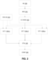
- Figure 2 is a diagram showing the steps of a method according to the invention as claimed.
- the VSD 110 is controlled (by the control device 120 or by any other entity) to inject a motor voltage or motor voltages depending on a control law voltage and an additional voltage component, such as a high-frequency component for example.
- the measuring unit 121 acquires an input signal such as measurements of the current (or currents for different phases) flowing through the motor 100.
- the input signal is an analog signal.
- the analog input signal y is processed by the delta-sigma modulation unit 122 to obtain the digital signal y ⁇ .
- step 203 in parallel to step 202, the one or several periodic signals s i (t) is/are computed or received from an external entity.
- each of the estimation units 123 estimates a signal y i based on the periodic signal received/computed at step 203 and based on the digital signal y ⁇ .
- control unit 124 adapts the control law of the VSD 110 and/or extracts harmonics at known frequencies to compute a monitoring value, for example to calculate RMS or THDI as explained above.
- the calculation of RMS or THDI can be followed by an optional step 206 of comparison of the RMS or THDI value with a preset threshold, and an alarm can be generated based on the result of the comparison, as explained above.
Landscapes
- Engineering & Computer Science (AREA)
- Power Engineering (AREA)
- Physics & Mathematics (AREA)
- Computer Hardware Design (AREA)
- Mathematical Physics (AREA)
- Control Of Electric Motors In General (AREA)
- Control Of Ac Motors In General (AREA)
Description
- The invention concerns signal processing, in particular while not exclusively, in the context of control of devices. More particularly, the invention may be used in the context of sensorless control of electrical motors.
- Electrical devices such as motors are generally powered via a variable speed drive connected to a main. Classic voltage/frequency control laws are more and more replaced by sensorless control laws that are able to control both the speed and the torque of the electrical motor, without a mechanical speed or position sensor.
- In the context of the present invention, "sensorless" does not refer to the complete absence of sensors but to the absence of some sensors, such as rotor speed or position sensors. It however generally relies on measurements of motor currents (or potentially of motor voltages).
- Sensorless control of devices, in particular electric motors, may rely on extraction of information through signal injection, based on a measured variable (such as the current values). High-frequency signal injection consists in superimposing a high-frequency signal to the control signals of electric motors. The measured current response of the motor to this supplementary excitation is then extracted from the current measurement and additional signal processing allows to retrieve the speed or the position of the rotor at low or even zero speed.
- The measured signal y(t) can be assumed to be of the form:

- yi are unknown signals (also called amplitudes hereafter) to be estimated;
- si are independent known periodic functions of period 1 (normalized time), of class Ii (piecewise) and globally of class Ii-1;
- ε « 1 is a known positive parameter; and
- O(εp ) is a small unknown signal which amplitude is of order εp (for some known p).
- The unknown signals yi can then be used to estimate the position of the rotor or its speed, so as to determine the control signal to be applied to the motor.
- Some known techniques may be used to retrieve the unknown signals yi:
- Band-pass filtering y(t) to isolate the desired frequency and extract the amplitude of the resulting signal using amplitude calculators such as described in
US patent 7,045,988 B2 ; - Using a procedure similar to heterodyning and sliding averages filters, which are basic Finite Impulse Response filters, to obtain the respective amplitudes of the components. This technique is for example described in A. K. Jebai, F. Malrait, P. Martin, and P. Rouchon, "Sensorless position estimation and control of permanent-magnet synchronous motors using a saturation model" in International Journal of Control, vol. 89, no. 3, pp. 535-549, 2016, and in P. Combes, A. K. Jebai, F. Malrait, P. Martin, and P. Rouchon, "Adding virtual measurements by signal injection" in American Control Conference, 2016, pp. 999-1005.
- When using High-Frequency signal injection for sensorless control of electric motors, for example, the desired frequency can be obtained by band-pass filtering of the signal y(t) and by using an arctangent function to retrieve the position of the rotor, as detailed in the document Yoon Y.-D. and Sul S.-K., "Sensorless Control for Induction Machines Based on Square-Wave Voltage Injection" in IEEE Transactions on Power Electronics, vol. 29, pp. 3637-3645, 2014.
- Wolfgang hammel et al:: "High-resolution sensorless position estimation using delta-sigma-modulated current measurement", ENERGY CONVERSION CONGRESS AND EXPOSITION (ECCE), 2011 IEEE, IEEE, 17 September 2011 (2011-09-17), pages 2717-2724, XP032067527, DOl: 10.1109/ECCE.2011.6064133 ISBN: 978-1-4577-0542-7 proposes a technique for injecting an alternating carrier voltage for sensorless position estimation. The high frequency current components are measured using delta-sigma-modulators.
-
GB 2 314 707 A -
US 2004/225468 A1 discloses a method involving fitting components of a motor control signal to a corresponding number of orthogonal pairs in a set of weighted orthogonal pairs. Frequency pairs providing a reduction in the mean squared error between current wave and the weighted orthogonal pairs that satisfy criteria are identified. Desired frequencies from the identified frequency pairs are compared with a harmonic model to determine a motor speed. -
EP 3 447 923 A1 provides a sigma-delta modulator (SDM) and associated system improving spectrum efficiency of wired interconnection. However, the known techniques suffer from a limited precision and require expensive fast Analog to Digital Converters ADCs, when ε is small, since it is imposed to measure at least two points per period ε, according to the Nyquist-Shannon theorem. - This lack of precision and cost problems apply, more generally, to the estimation of amplitudes of periodic signals in a measured signal.
- There are therefore needs to improve the estimation of amplitudes of periodic components of a measured analog signal.
- The invention is set out in the appended set of claims.
- The invention proposes to use delta-sigma modulators without preprocessing the analog signal, to retrieve an accurate representation of the analog input while being less expensive than other ADCs of similar quality. In addition, galvanic insulation can easily be embedded.
- According to the invention as claimed the control device comprises at least two filters, including a first filter and a second filter, the first filter is applied to the digital signal and to a first periodic signal, the second filter is applied to the digital signal and to a second periodic signal, and the first and second periodic signals are independent functions.
- Therefore, several information can be extracted from the measured analog signal.
- The first and second periodic signals are orthogonal.
- This improves the accuracy of the estimation of the amplitudes.
- According to some embodiments, the periodic signal or periodic signals is calculated by a computing unit of the control device based on a clock signal.
- This enables to predefine the periodic signals and to increase the responsiveness of the method.
- Alternatively, the periodic signal or periodic signals is/are received by the control device from an external device.
- This enables to improve the flexibility of the method as different periodic signals can be used over time.
- According to some embodiments, the control device is configured to control a variable speed drive in charge of an electric motor, the method comprises, before receiving the measured analog signal, controlling the variable speed drive to inject a motor voltage comprising a control law voltage and an additional voltage component. In that case, the external entity is the variable speed drive.
- Therefore, signal injection can be performed to obtain additional information about the electric motor and to enhance the control law of the electric motor.
- In complement, the additional voltage component can be a high-frequency component.
- This enables to facilitate obtaining the additional information even at low-speed.
- According to some embodiments, adapting the control law comprises estimating a rotor position and/or speed based on at least the amplitude signal.
- This enables to improve the control of the motor position/speed by the variable speed drive.
- According to some embodiments, the monitoring value calculated based on at least the amplitude signal can be:
- a Root Mean Square, RMS, value; and/or
- a Total Harmonic Distortion, THDI, value.
- According to some embodiments, the method may further comprise comparing the calculated monitoring value with a preset threshold to decide to issue or not an alert
- Therefore, an abnormal situation can be automatically detected and signaled.
- According to the invention as claimed, the first and second filters are Finite Impulse Response Filter, being a linear combination of basic blocks M, basic blocks M being iteratively defined by:


- Further objects, aspects, effects and details of the invention are described in the following detailed description of a number of exemplary embodiments, with reference to the drawings.
- By way of example only, the embodiments of the present disclosure will be described with reference to the accompanying drawings, wherein:
-
FIG. 1 represents a system according to the invention as claimed; -
FIG. 2 is a flowchart showing the steps of a method according to the invention as claimed. -
Figure 1 shows a system according to the invention as claimed. - On
Figure 1 , acontrol device 120 is included in a system comprising a variable speed drive, VSD, 110 and anelectrical motor 100, According to some embodiments, thecontrol device 120 may be included in theVSD 110. Thecontrol device 120 may also be used in any other context requiring signal processing of a measured signal to estimate amplitudes of periodic signals within the measured signal. - In
Figure 1 the amplitudes are used to adapt the control law of theelectrical motor 100. In particular, the unknown signals yi can be alternatively used to extract harmonics at known frequencies (for example in the context of Root Mean Square RMS value calculation, or Total Harmonic Distortion THDI calculation is sensors) so as to monitor these values. - No restriction is attached to the type of electrical motor, which can be for example a three-phase AC motor, such as a Synchronous Reluctance Motor, SynRM, a Permanent Magnet Synchronous Motor, PMSM, or an Induction machine also known as asynchronous motor.
- The
VSD 110 can be powered by apower source 111. - The
control device 120 may comprise ameasuring unit 121, such as current sensors, configured for measuring currents running through theelectric motor 100. OnFigure 1 , theVSD 100 is powered by a three-phase power source, for illustrative purposes only. In that context, the measuringunit 121 may measure currents on the three phases (or only two of them as the third one can be deduced from the two measured ones). - Alternatively, the measuring
unit 121 may be an interface communicating with a measuring unit of theVSD 110, when the VSD comprises such a measuring unit (current sensor) configured for measuring stator current(s). This enables to reduce the cost of thecontrol device 120, and to take advantage of the fact that VSDs are generally equipped with current measurement units. - The signal obtained by the measuring
unit 121 is an analog signal. - The
control device 120 further comprises a delta-sigma modulation unit 122 that is configured to apply a delta-sigma modulation to the analog signal obtained by the measuringunit 121. - Regular Analog to Digital Converters, ADCs, other than delta-sigma modulators, sample a received analog signal at given instants and output representations of the instantaneous value of the signal over N bits. To sample a signal of a given frequency, the Nyquist-Shannon theorem imposes to have two samples per period, which is called the Nyquist rate.
- Delta-sigma modulators are ADCs, which operate at higher frequencies but with a lower precision.
- To obtain an accurate measurement from the output signal of the Delta-Sigma modulator (whose frequency is for example 15 MHz and whose resolution is low, for example 1 bit), the measurement can be decimated by 3750 for instance (oversampling ratio), to obtain a signal sampled at lower frequencies (4 kHz in the example).
- Delta-sigma modulators yield a high-frequency 1-bit signal (called bitstream), which is proportional in average to the analog input. To retrieve an accurate representation of the analog input, the average over N (oversampling ratio) samples has to be taken.
- Delta-sigma modulators have the advantage to be less expensive than other ADCs of similar quality, and galvanic insulation can easily be embedded.
- The principle of a delta-sigma modulation is well known and is not further described in the present application.
- The
control device 120 further comprises at least one estimator 123 connected at the output of the delta-sigma modulation unit 122. OnFigure 1 , thecontrol device 120 comprises n estimation units 123.1 to 123.n, n being an integer equal to or greater than 1. - The invention therefore proposes to directly connect the delta-
sigma modulation unit 122 with the one or several estimation units 123 without preprocessing. - The estimation units 123 comprise computing capabilities or an electronic circuit that is/are configured to determine, based on a respective periodic signals s1(t), s2(t) ... sn(t), and based on the digital signal y ΔΣ output by the delta-
sigma modulation unit 122, amplitude signals yi corresponding to the respective periodic signals si(t). For example, the estimators can be implemented either on an Application Specific Integrated Circuit, ASIC, a Field-Programmable Gate Array, FPGA, or a Digital Signal Processor, DSP. - The periodic signals si(t) are provided by the
computing unit 125 or alternatively by an external entity. Thecomputing unit 125 may compute the periodic signals si(t) based on a clock signal. Thecomputing unit 125 may be integrated in the ASIC, FPGA or DSP mentioned above. Estimation units 123 are described hereafter. The estimation units 123 may be identical (but their outputs differ as they are fed with different periodic signals si(t)) or may be distinct. - The estimation units 123 comprise filters, such as Finite Impulse Response, FIR, filters, of
order orders 

- A family of FIR filters used in the estimation units 123 may be:


- More generally, the used FIR filter may be a linear combination of M 1, ..., Mk for which the sum of the coefficients is 1. The coefficients do not depend on the periodic signals si(t).
- The si(t), i varying between 1 and n, are orthogonal, for example orthogonal with respect to a scalar product over the set of 1-periodic functions, i.e.:

- The estimator ŷ i for the yi up to O(εp ) can be given by:

- The order p of the filter allows to adjust the accuracy of the estimators (more accuracy when p is high).
- The

sigma modulation unit 122. - An alternative to the above estimator ŷ i can be:

- The same estimators in the different estimation units 123.1-123.n can be used, provided that the si(t) are made orthogonal. The
computing unit 125 is configured to make the si orthogonal, if they are originally not (for example, if they are received from an external entity and they are not orthogonal). Original signals si' are therefore processed to obtain orthogonal signals si and the above formula are applied to the orthogonal signals si. Once the estimations ŷ i are obtained, thecomputing unit 125 may further be configured to calculate the estimations y'i in the original basis of signals si'. - The filters, applied to the signal y ΔΣ instead of y, estimate ŷ i such that ŷ i = yi (t) + O(εp ) + o(N-k ) + O(N -(l+1)), where k is the order of the delta-
sigma modulation unit 122, N is the oversampling ratio of the delta-sigma modulation unit 122 and
- For example, in the context of signal injection for sensorless control of the
motor 100 at low speed, the measured currents may be expressed as:

- The knowledge of y0 and y1 (and optionally of y2) may be used as parameters for the design of the
VSD 110 control laws. - y0, y1 (and y2) can be determined with accuracy using the low-cost delta-
sigma modulation unit 122, even if 1/ε is larger than the effective Nyquist frequencies of the yi . - Once the amplitudes yi has or have been obtained, they are transferred to the
control unit 124. Thecontrol unit 124 is configured to: - adapt the control law of the
VSD 110 based on the amplitude(s) yi, by optionally determining the speed and position of the rotor based on the amplitude(s) yi; and/or - the amplitude signals yi can be alternatively used to extract harmonics at known frequencies, for example in the context of the calculation of a monitoring value, such as Root Mean Square RMS value, or Total Harmonic Distortion THDI, so as to monitor this value. As an example, the
control unit 124 may further calculate the THDI and compare it with a preset threshold. Based on the result of the comparison, an alert may be generated, in particular if the THDI exceeds the preset threshold. - To this end, the
control unit 124 may comprise a processor, a memory (RAM, ROM, flash memory, etc.) and an output interface for controlling theVSD 110 or for issuing and transmitting an alarm signal. - An example of sensorless control of a motor of the SynRM type, using signal injection, is described hereafter.
- A model of the SynRM motor can be given by:


 (θ) is a rotation function of angle theta in positive trigonometric direction.
- The state of the motor is described by φSDQ , which is the vector of the stator flux in a rotor-oriented DQ frame, and θ, which is the angular position of the rotor.
- The vector of stator voltages in a stationary αβ frame, noted uSαβ is the control input, while ω, the rotor speed, is a disturbance input, which is to be obtained to achieve a proper control of the SynRM motor.
- When sensorless control is used, the sole available measurement is the vector of stator currents in the stationary αβ frame, noted ISαβ.
- Parameters of the model are the resistance Rs of the stator and the matrix of inductances

- When signal injection is used, the vector of stator voltages is:


u Sαβ. The high-frequency disturbance in the voltage vector creates a high-frequency in the stator flux, which becomes


- Estimating
I Sαβ and(θ) (respectively corresponding to y0 and y1 mentioned above) using the invention detailed above, allows to retrieve theta from (θ) =(θ)L -1(-θ) and use it together with
I Sαβ to computeu Sαβ in the control law. -
Figure 2 is a diagram showing the steps of a method according to the invention as claimed. - At a
step 200, theVSD 110 is controlled (by thecontrol device 120 or by any other entity) to inject a motor voltage or motor voltages depending on a control law voltage and an additional voltage component, such as a high-frequency component for example. - At
step 201, the measuringunit 121 acquires an input signal such as measurements of the current (or currents for different phases) flowing through themotor 100. The input signal is an analog signal. - At
step 202, the analog input signal y is processed by the delta-sigma modulation unit 122 to obtain the digital signal y ΔΣ. - At
step 203, in parallel to step 202, the one or several periodic signals si(t) is/are computed or received from an external entity. - At one or several steps 204.1-204.n, each of the estimation units 123 estimates a signal yi based on the periodic signal received/computed at
step 203 and based on the digital signal y ΔΣ. - At
step 205, thecontrol unit 124 adapts the control law of theVSD 110 and/or extracts harmonics at known frequencies to compute a monitoring value, for example to calculate RMS or THDI as explained above. - The calculation of RMS or THDI can be followed by an
optional step 206 of comparison of the RMS or THDI value with a preset threshold, and an alarm can be generated based on the result of the comparison, as explained above. - Although the present invention has been described above with reference to specific embodiments, it is not intended to be limited to the specific form set forth herein. Rather, the invention is limited only by the accompanying claims.
Claims (9)
- A method for estimating amplitudes of a periodic component in a measured signal, the measured signal corresponding to measurements of current flowing through an electric motor (100), wherein the method is performed by a control device (120) configured to control a variable speed drive (110) in charge of the electric motor (100),
wherein the control device (120) comprises at least two filters, including a first filter and a second filter, the method comprising the following consecutive operations:- controlling (200) the variable speed drive (110) to inject a motor voltage comprising a control law voltage and an additional voltage component into the electric motor (100);- receiving (201) said measured signal, the measured signal being analog;- performing (202) a delta-sigma modulation on the received analog signal to obtain a digital signal;- applying (204.1-204.n) the first filter to the product of the digital signal and a first periodic signal to estimate a first amplitude signal among said amplitudes, andapplying the second filter to the product of the digital signal and a second periodic signal to estimate a second amplitude signal among said amplitudes,wherein the first and second periodic signals are independent orthogonal functions, and wherein the at least two filters are Finite Impulse Response Filters, being a linear combination of basic blocks M, basic blocks M being iteratively defined by:
 where T is an integer multiple of the period of the periodic signals, and where f is a dummy function variable;- adapting (205) a control law of the electric motor (100) based on at least the first and second amplitude signals, or calculating (205) a monitoring value based on at least the first and second amplitude signals.
 - The method according to claim 1, wherein the periodic signals are calculated by a computing unit (125) of the control device (120) based on a clock signal.
- The method according to claim 1, wherein the periodic signals are received by the control device (120) from an external device.
- The method according to claim 1, wherein the additional voltage component is a high-frequency component.
- The method according to claim 1 or 4, wherein adapting the control law comprises estimating a rotor position and/or speed of the electric motor (100) based on at least the first and second amplitude signals.
- The method according to one of the preceding claims, wherein the monitoring value calculated based on at least the first and second amplitude signals is:- a Root Mean Square, RMS, value; and/or- a Total Harmonic Distortion, THDI, value.
- The method according to one of the preceding claims, further comprising comparing (206) the calculated monitoring value with a preset threshold to decide to issue or not an alert.
- A non-transitory computer-readable storage medium, with a computer program stored thereon, said computer program comprising instructions for, when executed by a processor, carrying out the steps of the method according to one of claims 1 to 7.
- A control device (120) configured for performing the method according to one of claims 1 to 7, the control device (120) comprising:a measuring unit (121) configured for receiving the measured analog signal;a delta-sigma modulation unit (122) configured to perform the delta-sigma modulation on the received analog signal to obtain the digital signal;a first estimation unit (123.1) comprising the first filter to estimate the first amplitude signal among said amplitudes;a second estimation unit (123.2) comprising the second filter to estimate the second amplitude signal among said amplitudes;a control unit (124) configured for:- adapting the control law of the electric motor (100) based on at least the first and second amplitude signals; or- calculating the monitoring value based on at least the first and second amplitude signals, and comparing the calculated monitoring value with a preset threshold to decide to issue or not an alert.
Priority Applications (4)
| Application Number | Priority Date | Filing Date | Title |
|---|---|---|---|
| EP19305291.7A EP3709500B1 (en) | 2019-03-12 | 2019-03-12 | Estimation of the amplitude of a periodic component in a measured signal through a delta-sigma modulator |
| ES19305291T ES2993159T3 (en) | 2019-03-12 | 2019-03-12 | Estimation of the amplitude of a periodic component in a measured signal through a delta-sigma modulator |
| US16/793,689 US11349425B2 (en) | 2019-03-12 | 2020-02-18 | Estimation of the amplitude of a periodic component in a measured signal through a delta-sigma modulator |
| CN202010169481.4A CN111697893A (en) | 2019-03-12 | 2020-03-12 | Estimating the amplitude of a periodic component in a measured signal by a sigma modulator |
Applications Claiming Priority (1)
| Application Number | Priority Date | Filing Date | Title |
|---|---|---|---|
| EP19305291.7A EP3709500B1 (en) | 2019-03-12 | 2019-03-12 | Estimation of the amplitude of a periodic component in a measured signal through a delta-sigma modulator |
Publications (2)
| Publication Number | Publication Date |
|---|---|
| EP3709500A1 EP3709500A1 (en) | 2020-09-16 |
| EP3709500B1 true EP3709500B1 (en) | 2024-11-06 |
Family
ID=65818488
Family Applications (1)
| Application Number | Title | Priority Date | Filing Date |
|---|---|---|---|
| EP19305291.7A Active EP3709500B1 (en) | 2019-03-12 | 2019-03-12 | Estimation of the amplitude of a periodic component in a measured signal through a delta-sigma modulator |
Country Status (4)
| Country | Link |
|---|---|
| US (1) | US11349425B2 (en) |
| EP (1) | EP3709500B1 (en) |
| CN (1) | CN111697893A (en) |
| ES (1) | ES2993159T3 (en) |
Families Citing this family (4)
| Publication number | Priority date | Publication date | Assignee | Title |
|---|---|---|---|---|
| ES2982473T3 (en) | 2020-12-17 | 2024-10-16 | Schneider Toshiba Inverter Europe Sas | Sensor loss control of a motor by variable frequency signal injection |
| ES2971897T3 (en) | 2020-12-23 | 2024-06-10 | Schneider Toshiba Inverter Europe Sas | Variable speed drive for sensorless PWM control of an AC motor with current noise rejection |
| CN115776257B (en) * | 2022-10-25 | 2025-12-19 | 中国铁道科学研究院集团有限公司电子计算技术研究所 | Method and system for realizing secondary filtering of brushless electric tuning of unmanned aerial vehicle |
| EP4712334A1 (en) | 2024-09-13 | 2026-03-18 | Schneider Toshiba Inverter Europe SAS | A method of determining the operating state of an electric machine for the sensorless control of the electric machine with signal injection |
Citations (1)
| Publication number | Priority date | Publication date | Assignee | Title |
|---|---|---|---|---|
| EP3447923A1 (en) * | 2017-08-25 | 2019-02-27 | MediaTek Inc. | Sigma-delta modulator and associated system improving spectrum efficiency of wired interconnection |
Family Cites Families (8)
| Publication number | Priority date | Publication date | Assignee | Title |
|---|---|---|---|---|
| GB2314707B (en) * | 1996-06-25 | 2000-01-19 | Racal Res Ltd | Sigma-delta analogue-to-digital conversion circuits |
| JP4370754B2 (en) | 2002-04-02 | 2009-11-25 | 株式会社安川電機 | Sensorless control device and control method for AC motor |
| US6876944B2 (en) * | 2002-09-04 | 2005-04-05 | Her Majesty The Queen In Right Of Canada, As Represented By The Minister Of National Defence | Motor speed estimation for stabilized motor control |
| DE102010032296B4 (en) * | 2009-08-26 | 2014-05-28 | Sew-Eurodrive Gmbh & Co Kg | Method for processing a measured value signal representing an analogue value for output current of an inverter and apparatus for carrying out the method |
| US9325263B1 (en) * | 2014-11-05 | 2016-04-26 | Stmicroelectronics S.R.L. | Sensorless rotor angle detection circuit and method for a permanent magnet synchronous machine |
| GB2537802A (en) * | 2015-02-13 | 2016-11-02 | Univ Sheffield | Parameter estimation and control method and apparatus |
| US9742430B1 (en) * | 2016-08-19 | 2017-08-22 | Infineon Technologies Ag | System and method for analog to digital conversion |
| US9948224B1 (en) * | 2016-10-17 | 2018-04-17 | General Electric Company | System and method for sensorless control of electric machines using magnetic alignment signatures |
-
2019
- 2019-03-12 EP EP19305291.7A patent/EP3709500B1/en active Active
- 2019-03-12 ES ES19305291T patent/ES2993159T3/en active Active
-
2020
- 2020-02-18 US US16/793,689 patent/US11349425B2/en active Active
- 2020-03-12 CN CN202010169481.4A patent/CN111697893A/en active Pending
Patent Citations (1)
| Publication number | Priority date | Publication date | Assignee | Title |
|---|---|---|---|---|
| EP3447923A1 (en) * | 2017-08-25 | 2019-02-27 | MediaTek Inc. | Sigma-delta modulator and associated system improving spectrum efficiency of wired interconnection |
Non-Patent Citations (1)
| Title |
|---|
| SURROOP DILSHAD ET AL: "A new demodulation procedure for a class of multiplexed signals", IECON 2019 - 45TH ANNUAL CONFERENCE OF THE IEEE INDUSTRIAL ELECTRONICS SOCIETY, IEEE, vol. 1, 14 October 2019 (2019-10-14), pages 48 - 53, XP033670621, DOI: 10.1109/IECON.2019.8927835 * |
Also Published As
| Publication number | Publication date |
|---|---|
| US20200295693A1 (en) | 2020-09-17 |
| CN111697893A (en) | 2020-09-22 |
| US11349425B2 (en) | 2022-05-31 |
| EP3709500A1 (en) | 2020-09-16 |
| ES2993159T3 (en) | 2024-12-23 |
Similar Documents
| Publication | Publication Date | Title |
|---|---|---|
| US11349425B2 (en) | Estimation of the amplitude of a periodic component in a measured signal through a delta-sigma modulator | |
| JP5490601B2 (en) | Method for determining the position of the magnetic flux vector of a motor | |
| EP3156811B1 (en) | Method and system for detecting an open phase fault in a multi-phase electric machine | |
| JP6695594B2 (en) | Initial position estimation device for motor rotor | |
| CN104779877A (en) | Torque estimating system for synchronous electric motor | |
| KR20190064832A (en) | Parameter estimation method and apparatus of Surface Mounted Permanent Magnet Synchronous Motor | |
| Weber et al. | Increased signal-to-noise ratio of sensorless control using current oversampling | |
| CN103827683A (en) | A method of determining stationary signals for the diagnostics of an electromechanical system | |
| KR102596568B1 (en) | Device and method for estimating rotor angle in motor | |
| JP5909658B2 (en) | Motor constant calculation method and motor constant calculation apparatus for permanent magnet type synchronous motor | |
| CN106357187A (en) | Electrically-excited synchronous motor rotor initial position identifying system and method | |
| CN103647482A (en) | Brushless DC (direct current) motor 180-degree square wave control method and module and converter | |
| JP5942094B2 (en) | Motor constant calculation method and motor constant calculation device for PM motor | |
| CN107210691B (en) | Angle error correction device for position detector and angle error correction method | |
| JP2002171799A (en) | Vector control method and vector control device for ac motor | |
| KR100881360B1 (en) | Sensorless vector control device and method of induction motor | |
| JP6108114B2 (en) | Control device for permanent magnet type synchronous motor | |
| KR100732512B1 (en) | Method and apparatus for measuring parameters of induction motors | |
| KR101426485B1 (en) | Device for controlling AC motor | |
| JPWO2022201344A5 (en) | ||
| EP3244528A1 (en) | Power conversion device and control method for power conversion device | |
| Kubota et al. | Measurement of high frequency impedance characteristics for induction machine at zero stator frequency by using FPGA | |
| JP6673175B2 (en) | Induction motor control system | |
| JP2014204489A (en) | Rotary machine control device | |
| KR100659151B1 (en) | Speed Control Method of Brushless DC Motor Using Two Hall Sensors |
Legal Events
| Date | Code | Title | Description |
|---|---|---|---|
| PUAI | Public reference made under article 153(3) epc to a published international application that has entered the european phase |
Free format text: ORIGINAL CODE: 0009012 |
|
| STAA | Information on the status of an ep patent application or granted ep patent |
Free format text: STATUS: THE APPLICATION HAS BEEN PUBLISHED |
|
| AK | Designated contracting states |
Kind code of ref document: A1 Designated state(s): AL AT BE BG CH CY CZ DE DK EE ES FI FR GB GR HR HU IE IS IT LI LT LU LV MC MK MT NL NO PL PT RO RS SE SI SK SM TR |
|
| AX | Request for extension of the european patent |
Extension state: BA ME |
|
| STAA | Information on the status of an ep patent application or granted ep patent |
Free format text: STATUS: REQUEST FOR EXAMINATION WAS MADE |
|
| 17P | Request for examination filed |
Effective date: 20210304 |
|
| RBV | Designated contracting states (corrected) |
Designated state(s): AL AT BE BG CH CY CZ DE DK EE ES FI FR GB GR HR HU IE IS IT LI LT LU LV MC MK MT NL NO PL PT RO RS SE SI SK SM TR |
|
| STAA | Information on the status of an ep patent application or granted ep patent |
Free format text: STATUS: EXAMINATION IS IN PROGRESS |
|
| 17Q | First examination report despatched |
Effective date: 20220209 |
|
| GRAP | Despatch of communication of intention to grant a patent |
Free format text: ORIGINAL CODE: EPIDOSNIGR1 |
|
| STAA | Information on the status of an ep patent application or granted ep patent |
Free format text: STATUS: GRANT OF PATENT IS INTENDED |
|
| INTG | Intention to grant announced |
Effective date: 20240531 |
|
| GRAS | Grant fee paid |
Free format text: ORIGINAL CODE: EPIDOSNIGR3 |
|
| GRAA | (expected) grant |
Free format text: ORIGINAL CODE: 0009210 |
|
| STAA | Information on the status of an ep patent application or granted ep patent |
Free format text: STATUS: THE PATENT HAS BEEN GRANTED |
|
| AK | Designated contracting states |
Kind code of ref document: B1 Designated state(s): AL AT BE BG CH CY CZ DE DK EE ES FI FR GB GR HR HU IE IS IT LI LT LU LV MC MK MT NL NO PL PT RO RS SE SI SK SM TR |
|
| REG | Reference to a national code |
Ref country code: GB Ref legal event code: FG4D |
|
| REG | Reference to a national code |
Ref country code: CH Ref legal event code: EP |
|
| REG | Reference to a national code |
Ref country code: DE Ref legal event code: R096 Ref document number: 602019061448 Country of ref document: DE |
|
| REG | Reference to a national code |
Ref country code: IE Ref legal event code: FG4D |
|
| REG | Reference to a national code |
Ref country code: ES Ref legal event code: FG2A Ref document number: 2993159 Country of ref document: ES Kind code of ref document: T3 Effective date: 20241223 |
|
| REG | Reference to a national code |
Ref country code: LT Ref legal event code: MG9D |
|
| REG | Reference to a national code |
Ref country code: NL Ref legal event code: MP Effective date: 20241106 |
|
| PG25 | Lapsed in a contracting state [announced via postgrant information from national office to epo] |
Ref country code: PT Free format text: LAPSE BECAUSE OF FAILURE TO SUBMIT A TRANSLATION OF THE DESCRIPTION OR TO PAY THE FEE WITHIN THE PRESCRIBED TIME-LIMIT Effective date: 20250306 Ref country code: IS Free format text: LAPSE BECAUSE OF FAILURE TO SUBMIT A TRANSLATION OF THE DESCRIPTION OR TO PAY THE FEE WITHIN THE PRESCRIBED TIME-LIMIT Effective date: 20250306 Ref country code: HR Free format text: LAPSE BECAUSE OF FAILURE TO SUBMIT A TRANSLATION OF THE DESCRIPTION OR TO PAY THE FEE WITHIN THE PRESCRIBED TIME-LIMIT Effective date: 20241106 |
|
| PG25 | Lapsed in a contracting state [announced via postgrant information from national office to epo] |
Ref country code: NL Free format text: LAPSE BECAUSE OF FAILURE TO SUBMIT A TRANSLATION OF THE DESCRIPTION OR TO PAY THE FEE WITHIN THE PRESCRIBED TIME-LIMIT Effective date: 20241106 Ref country code: FI Free format text: LAPSE BECAUSE OF FAILURE TO SUBMIT A TRANSLATION OF THE DESCRIPTION OR TO PAY THE FEE WITHIN THE PRESCRIBED TIME-LIMIT Effective date: 20241106 |
|
| REG | Reference to a national code |
Ref country code: AT Ref legal event code: MK05 Ref document number: 1740491 Country of ref document: AT Kind code of ref document: T Effective date: 20241106 |
|
| PG25 | Lapsed in a contracting state [announced via postgrant information from national office to epo] |
Ref country code: BG Free format text: LAPSE BECAUSE OF FAILURE TO SUBMIT A TRANSLATION OF THE DESCRIPTION OR TO PAY THE FEE WITHIN THE PRESCRIBED TIME-LIMIT Effective date: 20241106 |
|
| PG25 | Lapsed in a contracting state [announced via postgrant information from national office to epo] |
Ref country code: NO Free format text: LAPSE BECAUSE OF FAILURE TO SUBMIT A TRANSLATION OF THE DESCRIPTION OR TO PAY THE FEE WITHIN THE PRESCRIBED TIME-LIMIT Effective date: 20250206 |
|
| PG25 | Lapsed in a contracting state [announced via postgrant information from national office to epo] |
Ref country code: AT Free format text: LAPSE BECAUSE OF FAILURE TO SUBMIT A TRANSLATION OF THE DESCRIPTION OR TO PAY THE FEE WITHIN THE PRESCRIBED TIME-LIMIT Effective date: 20241106 Ref country code: LV Free format text: LAPSE BECAUSE OF FAILURE TO SUBMIT A TRANSLATION OF THE DESCRIPTION OR TO PAY THE FEE WITHIN THE PRESCRIBED TIME-LIMIT Effective date: 20241106 Ref country code: GR Free format text: LAPSE BECAUSE OF FAILURE TO SUBMIT A TRANSLATION OF THE DESCRIPTION OR TO PAY THE FEE WITHIN THE PRESCRIBED TIME-LIMIT Effective date: 20250207 |
|
| PG25 | Lapsed in a contracting state [announced via postgrant information from national office to epo] |
Ref country code: PL Free format text: LAPSE BECAUSE OF FAILURE TO SUBMIT A TRANSLATION OF THE DESCRIPTION OR TO PAY THE FEE WITHIN THE PRESCRIBED TIME-LIMIT Effective date: 20241106 |
|
| PG25 | Lapsed in a contracting state [announced via postgrant information from national office to epo] |
Ref country code: RS Free format text: LAPSE BECAUSE OF FAILURE TO SUBMIT A TRANSLATION OF THE DESCRIPTION OR TO PAY THE FEE WITHIN THE PRESCRIBED TIME-LIMIT Effective date: 20250206 |
|
| PG25 | Lapsed in a contracting state [announced via postgrant information from national office to epo] |
Ref country code: SM Free format text: LAPSE BECAUSE OF FAILURE TO SUBMIT A TRANSLATION OF THE DESCRIPTION OR TO PAY THE FEE WITHIN THE PRESCRIBED TIME-LIMIT Effective date: 20241106 |
|
| PG25 | Lapsed in a contracting state [announced via postgrant information from national office to epo] |
Ref country code: DK Free format text: LAPSE BECAUSE OF FAILURE TO SUBMIT A TRANSLATION OF THE DESCRIPTION OR TO PAY THE FEE WITHIN THE PRESCRIBED TIME-LIMIT Effective date: 20241106 |
|
| PGFP | Annual fee paid to national office [announced via postgrant information from national office to epo] |
Ref country code: ES Payment date: 20250423 Year of fee payment: 7 |
|
| PG25 | Lapsed in a contracting state [announced via postgrant information from national office to epo] |
Ref country code: EE Free format text: LAPSE BECAUSE OF FAILURE TO SUBMIT A TRANSLATION OF THE DESCRIPTION OR TO PAY THE FEE WITHIN THE PRESCRIBED TIME-LIMIT Effective date: 20241106 |
|
| PG25 | Lapsed in a contracting state [announced via postgrant information from national office to epo] |
Ref country code: RO Free format text: LAPSE BECAUSE OF FAILURE TO SUBMIT A TRANSLATION OF THE DESCRIPTION OR TO PAY THE FEE WITHIN THE PRESCRIBED TIME-LIMIT Effective date: 20241106 |
|
| PG25 | Lapsed in a contracting state [announced via postgrant information from national office to epo] |
Ref country code: SK Free format text: LAPSE BECAUSE OF FAILURE TO SUBMIT A TRANSLATION OF THE DESCRIPTION OR TO PAY THE FEE WITHIN THE PRESCRIBED TIME-LIMIT Effective date: 20241106 |
|
| PG25 | Lapsed in a contracting state [announced via postgrant information from national office to epo] |
Ref country code: CZ Free format text: LAPSE BECAUSE OF FAILURE TO SUBMIT A TRANSLATION OF THE DESCRIPTION OR TO PAY THE FEE WITHIN THE PRESCRIBED TIME-LIMIT Effective date: 20241106 |
|
| REG | Reference to a national code |
Ref country code: DE Ref legal event code: R097 Ref document number: 602019061448 Country of ref document: DE |
|
| PG25 | Lapsed in a contracting state [announced via postgrant information from national office to epo] |
Ref country code: SE Free format text: LAPSE BECAUSE OF FAILURE TO SUBMIT A TRANSLATION OF THE DESCRIPTION OR TO PAY THE FEE WITHIN THE PRESCRIBED TIME-LIMIT Effective date: 20241106 |
|
| PLBE | No opposition filed within time limit |
Free format text: ORIGINAL CODE: 0009261 |
|
| STAA | Information on the status of an ep patent application or granted ep patent |
Free format text: STATUS: NO OPPOSITION FILED WITHIN TIME LIMIT |
|
| PG25 | Lapsed in a contracting state [announced via postgrant information from national office to epo] |
Ref country code: MC Free format text: LAPSE BECAUSE OF FAILURE TO SUBMIT A TRANSLATION OF THE DESCRIPTION OR TO PAY THE FEE WITHIN THE PRESCRIBED TIME-LIMIT Effective date: 20241106 |
|
| 26N | No opposition filed |
Effective date: 20250807 |
|
| REG | Reference to a national code |
Ref country code: CH Ref legal event code: H13 Free format text: ST27 STATUS EVENT CODE: U-0-0-H10-H13 (AS PROVIDED BY THE NATIONAL OFFICE) Effective date: 20251024 |
|
| PG25 | Lapsed in a contracting state [announced via postgrant information from national office to epo] |
Ref country code: LU Free format text: LAPSE BECAUSE OF NON-PAYMENT OF DUE FEES Effective date: 20250312 |
|
| REG | Reference to a national code |
Ref country code: BE Ref legal event code: MM Effective date: 20250331 |
|
| PG25 | Lapsed in a contracting state [announced via postgrant information from national office to epo] |
Ref country code: BE Free format text: LAPSE BECAUSE OF NON-PAYMENT OF DUE FEES Effective date: 20250331 |
|
| PG25 | Lapsed in a contracting state [announced via postgrant information from national office to epo] |
Ref country code: CH Free format text: LAPSE BECAUSE OF NON-PAYMENT OF DUE FEES Effective date: 20250331 |
|
| PG25 | Lapsed in a contracting state [announced via postgrant information from national office to epo] |
Ref country code: IE Free format text: LAPSE BECAUSE OF NON-PAYMENT OF DUE FEES Effective date: 20250312 |
|
| PGFP | Annual fee paid to national office [announced via postgrant information from national office to epo] |
Ref country code: GB Payment date: 20260324 Year of fee payment: 8 |
|
| PGFP | Annual fee paid to national office [announced via postgrant information from national office to epo] |
Ref country code: DE Payment date: 20260326 Year of fee payment: 8 |
|
| PGFP | Annual fee paid to national office [announced via postgrant information from national office to epo] |
Ref country code: IT Payment date: 20260320 Year of fee payment: 8 |
|
| PGFP | Annual fee paid to national office [announced via postgrant information from national office to epo] |
Ref country code: FR Payment date: 20260323 Year of fee payment: 8 |