EP3709485A1 - Generators operable with shared oil systems and independent oil systems - Google Patents
Generators operable with shared oil systems and independent oil systems Download PDFInfo
- Publication number
- EP3709485A1 EP3709485A1 EP19211118.5A EP19211118A EP3709485A1 EP 3709485 A1 EP3709485 A1 EP 3709485A1 EP 19211118 A EP19211118 A EP 19211118A EP 3709485 A1 EP3709485 A1 EP 3709485A1
- Authority
- EP
- European Patent Office
- Prior art keywords
- oil
- port
- selector
- stator
- generator
- Prior art date
- Legal status (The legal status is an assumption and is not a legal conclusion. Google has not performed a legal analysis and makes no representation as to the accuracy of the status listed.)
- Granted
Links
Images



Classifications
-
- F—MECHANICAL ENGINEERING; LIGHTING; HEATING; WEAPONS; BLASTING
- F16—ENGINEERING ELEMENTS AND UNITS; GENERAL MEASURES FOR PRODUCING AND MAINTAINING EFFECTIVE FUNCTIONING OF MACHINES OR INSTALLATIONS; THERMAL INSULATION IN GENERAL
- F16N—LUBRICATING
- F16N7/00—Arrangements for supplying oil or unspecified lubricant from a stationary reservoir or the equivalent in or on the machine or member to be lubricated
- F16N7/38—Arrangements for supplying oil or unspecified lubricant from a stationary reservoir or the equivalent in or on the machine or member to be lubricated with a separate pump; Central lubrication systems
- F16N7/385—Central lubrication systems
-
- F—MECHANICAL ENGINEERING; LIGHTING; HEATING; WEAPONS; BLASTING
- F16—ENGINEERING ELEMENTS AND UNITS; GENERAL MEASURES FOR PRODUCING AND MAINTAINING EFFECTIVE FUNCTIONING OF MACHINES OR INSTALLATIONS; THERMAL INSULATION IN GENERAL
- F16N—LUBRICATING
- F16N7/00—Arrangements for supplying oil or unspecified lubricant from a stationary reservoir or the equivalent in or on the machine or member to be lubricated
- F16N7/38—Arrangements for supplying oil or unspecified lubricant from a stationary reservoir or the equivalent in or on the machine or member to be lubricated with a separate pump; Central lubrication systems
- F16N7/40—Arrangements for supplying oil or unspecified lubricant from a stationary reservoir or the equivalent in or on the machine or member to be lubricated with a separate pump; Central lubrication systems in a closed circulation system
-
- H—ELECTRICITY
- H02—GENERATION; CONVERSION OR DISTRIBUTION OF ELECTRIC POWER
- H02K—DYNAMO-ELECTRIC MACHINES
- H02K7/00—Arrangements for handling mechanical energy structurally associated with dynamo-electric machines, e.g. structural association with mechanical driving motors or auxiliary dynamo-electric machines
- H02K7/18—Structural association of electric generators with mechanical driving motors, e.g. with turbines
- H02K7/1807—Rotary generators
- H02K7/1823—Rotary generators structurally associated with turbines or similar engines
-
- H—ELECTRICITY
- H02—GENERATION; CONVERSION OR DISTRIBUTION OF ELECTRIC POWER
- H02K—DYNAMO-ELECTRIC MACHINES
- H02K9/00—Arrangements for cooling or ventilating
- H02K9/19—Arrangements for cooling or ventilating for machines with closed casing and closed-circuit cooling using a liquid cooling medium, e.g. oil
- H02K9/193—Arrangements for cooling or ventilating for machines with closed casing and closed-circuit cooling using a liquid cooling medium, e.g. oil with provision for replenishing the cooling medium; with means for preventing leakage of the cooling medium
-
- H—ELECTRICITY
- H02—GENERATION; CONVERSION OR DISTRIBUTION OF ELECTRIC POWER
- H02K—DYNAMO-ELECTRIC MACHINES
- H02K9/00—Arrangements for cooling or ventilating
- H02K9/19—Arrangements for cooling or ventilating for machines with closed casing and closed-circuit cooling using a liquid cooling medium, e.g. oil
- H02K9/197—Arrangements for cooling or ventilating for machines with closed casing and closed-circuit cooling using a liquid cooling medium, e.g. oil in which the rotor or stator space is fluid-tight, e.g. to provide for different cooling media for rotor and stator
-
- H—ELECTRICITY
- H02—GENERATION; CONVERSION OR DISTRIBUTION OF ELECTRIC POWER
- H02K—DYNAMO-ELECTRIC MACHINES
- H02K2213/00—Specific aspects, not otherwise provided for and not covered by codes H02K2201/00 - H02K2211/00
- H02K2213/09—Machines characterised by the presence of elements which are subject to variation, e.g. adjustable bearings, reconfigurable windings, variable pitch ventilators
Definitions
- the subject matter disclosed herein generally relates to electrical systems, and more particularly to generators for electrical systems that are operable with both shared oil systems and independent oil systems.
- Generators provide electrical power to electrical devices connected to the electrical system, typically using mechanical rotation applied to the generator by an engine.
- the mechanical rotation rotates a rotor carrying magnet elements relative to a stator winding such that magnetic flux provided by the magnetic elements induces a flow of electric current in the stator windings.
- generators typically require cooling.
- the cooling is provided by circulating oil through the generator, generally by connecting the generator to the engine oil system or to an independent oil system.
- the oil circuit of a generator provisioned with oil from a shared oil system typically has a flow path that differs from that of a generator provisioned with oil from an independent oil system. For that reason generators configured for connection to an independent oil system are typically not interchangeable with generators configured for connection to a shared oil system. Likewise, generators configured for connection to a shared oil system are typically not interchangeable with generators configured for connection to an independent oil system.
- the oil source dependency can add cost to sparing such generators.
- a generator in certain embodiments, includes a stator with a stator winding, a rotor with a field winding and supported for rotation relative to the stator, and a housing enclosing the stator and the rotor.
- the housing has a shared system port connected to a shared system port by a selector, the selector fluidly coupling the stator and one of the independent system port and the shared system port, and the selector fluidly separating the stator from the other of the independent system port and the shared system port.
- further embodiments may include wherein the housing has a conduit with defining a flow area arranged within an interior of the housing, wherein the selector spans the flow area of the conduit.
- selector comprises a flow passer having a tool engagement feature, wherein the tool engagement feature is located within an interior of the housing.
- selector comprises a flow blocker, the flow blocker having a first seal member extending about a first end of the selector and compressively fixed between the housing and a first seat of the selector, and a second seal member extending about a second end of the selector, the second end longitudinally opposite the first end, the second seal member compressively fixed between the housing and a second seat of the selector.
- further embodiments may include wherein the selector comprises a flow passer with a flow passage extending therethrough, the flow passage of the flow passer fluidly coupling the stator to the one of the independent system port and the shared system port.
- selector comprises a flow blocker with a monolithic body, the monolithic body of the flow blocker fluidly separating the stator from the other of the independent system port and the shared system port.
- further embodiments may include a flow blocker fixed within the first seat and fluidly separating the shared system port from the stator, and a flow passer fixed within the second seat and fluidly coupling the independent system port to the stator.
- further embodiments may include a flow passer fixed within the first seat and fluidly coupling the shared system port to the stator, and a flow blocker fixed within the second seat and fluidly separating the independent system port from the stator.
- further embodiments may include wherein at least one of the first seat and the second seat extend through a conduit arranged within an interior of the housing.
- further embodiments may include wherein the housing has a drive end and an anti-drive end, wherein the shared system port is arranged on the drive end of the housing, wherein the independent system port is arranged between the drive end and the anti-drive end of the housing or the anti-drive end of the housing.
- further embodiments may include wherein the shared system port is a shared system oil-in port, wherein the independent system port is an independent system oil-in port, and wherein the housing has a shared system oil-out port and an independent system oil-out port connected to the selector.
- further embodiments may include a scavenge pump connecting the independent system oil-out port to the selector, and an inline screen connecting the shared system oil-out port to the selector.
- further embodiments may include an inline screen connecting the shared system oil-out port to the selector, and a scavenge filter connecting the independent system oil-out port to the selector.
- further embodiments may include wherein the shared system port is a shared system scavenge port, wherein the independent system port is an independent system oil-in port, the generator having a scavenge filter bypass conduit connecting the selector to the shared system scavenge port and a check valve connecting the selector to the independent system oil-in port.
- selector is an oil-in system selector
- the generator having an oil-out selector connected to the oil-in selector by the stator and a scavenge selector connected to the oil-in selector by the rotor.
- a generator arrangement in accordance with certain embodiments includes a generator as described above and an accessory gearbox.
- the accessory gearbox has an accessory mount supporting the generator, a scavenge selector is connected to the oil-in selector by the rotor, and a plug seated in the independent system port.
- a method of making a generator includes, at a housing having a shared system port and an independent system port, enclosing a stator with a stator winding in the housing and supporting a rotor with a rotor winding for rotation relative to the stator.
- the stator is fluidly coupled with one of the shared system port and the independent system port by the selector, and the stator is fluidly separated from the other of the shared system port and the independent system port with the selector.
- further embodiments may include fluidly coupling the stator with the other of the shared system port and the independent system port with the selector, and fluidly separating the stator from the other of the of the shared system port and the independent system port with the selector.
- a singular housing provides capability for the generator to operate with either a shared oil system or an independent oil system.
- generators described herein can be configured for operation with either a shared oil system or an independent oil system by configuring selectors arranged within the housing of the generator. It is also contemplated that the selectors be configured, and as required re-configured, for operation with either shared oil systems or independent oil systems by changing the placement of flow passers and flow blockers disposed within the housing and inter changeable among selector seats arranged within the housing.
- FIG. 1 a partial view of an exemplary embodiment of a generator in accordance with the disclosure is shown in FIG. 1 and is designated generally by reference character 100.
- FIG. 2-8 Other embodiments of generators, generator arrangements, and methods of making generators in accordance with the present disclosure, or aspects thereof, are provided in Figs. 2-8 , as will be described.
- the generators and generator arrangements described herein can be used with shared oil systems or independent oil systems, such engine oil systems on aircraft main engines and auxiliary power units, though the present disclosure is not limited to aircraft engines or to any particular type of oil system in general.
- a first generator arrangement 10 and a second generator arrangement 12 are shown.
- the generator 100 is operatively associated with a gas turbine engine 14 having an engine oil system 16.
- the generator 100 is arranged to circulate shared source oil 18 from engine oil system 16.
- the generator 100 is arranged to circulate independent source oil 20 from an independent oil system 22, shown in dashed outline.
- the gas turbine engine 14 includes a compressor section 24, a combustor section 26, and a turbine section 28.
- the gas turbine engine 14 also includes a power-take-off (PTO) shaft 30 and an accessory gearbox 32 with an accessory mount 34.
- the compressor section 24 is operably associated with turbine section 28 and is arranged to receive therefrom mechanical work. During operation, the compressor section 24 ingests air from the external environment and compresses the air using the mechanical work provided by the turbine section 28. The compressed air is communicated to the combustion section 26, which generates a flow of high pressure combustion products and communicates the high pressure combustion products to the turbine section 28.
- the turbine section 28 expands the high pressure combustion products, extracts work from the high pressure combustion products as they expand, and communicates the work to the compressor section 24. A portion of the work extracted by the turbine section 28 is also communicated to the generator 100 as mechanical rotation through the accessory gearbox 32, though the PTO shaft 30. The mechanical rotation rotates a rotor 106 (shown in FIG. 2 ) of the generator 100 to generate electrical power, which is used to power electrical devices connected to the generator 100.
- the generator 100 heat is generated during the operation of the generator 100.
- oil received from either the engine oil system 16 or the independent oil system 22 is circulated through the generator 100.
- the generator includes an oil circuit 162 (shown in FIG. 2 ) having a plurality of selectors, e.g., the oil-in selectors 174, the oil-out selector 176, and the scavenge selector 178 (shown in FIG.
- the selectors arranged to configure (and re-configured, as appropriate) the generator 100 to circulate oil from either the engine oil system 16 or the independent oil system 22. While shown and described herein as employing oil for coolant, those of skill in art the will appreciate that generators employing other types of fluids for cooling and/or lubrication can also benefit from the present disclosure.
- the generator 100 includes a housing 102, a stator 104, and a rotor 106.
- the stator 104 is arranged within the housing 102 and the rotor 106 is supported for rotation relative to the stator 104.
- the generator also includes the oil circuit 162, which is configurable to circulate oil from either the engine oil system 16 or the independent oil system 22, as will be described.
- the housing 102 has a drive end 114 and an anti-drive end 116.
- the drive end 114 includes a mounting feature 118 configured and adapted to support the generator 100 at the accessory mount 34 (shown in FIG. 1 ) of the accessory gearbox 32 (shown in FIG. 1 ).
- a shared system oil-in port 120, a shared system oil-out port 122, and a shared system scavenge port 124 each extend through the housing 102 at the drive end 114 of the housing 102 and are in fluid communication with an interior 126 of the housing 102.
- each of the shared system oil-in port 120, shared system oil-out port 122, and the shared system scavenge port 124 are axially overlapped by the accessory mount 34 and are arranged to communicate shared source oil 18 (shown in FIG. 1 ) between the generator 100 and the engine oil system 16 (shown in FIG. 1 ).
- a case pressure relief valve 128 is also located on the drive end 114 of the housing 102 for relieving pressure from the interior 126 of the housing 102 when the generator 100 is supplied the independent source oil 20 (shown in FIG. 1 ) from the independent oil system 22 (shown in FIG. 1 ).
- the housing 102 also includes an independent system oil-in port 130, an independent system oil-out port 132, and an independent system pressure oil-fill port 134.
- Each of the independent system oil-in port 130, the independent system oil-out port 132, and the independent system pressure oil-fill port 134 extend through the housing 102 at locations other than the drive end 114 of the housing 102, e.g., on upper and lower surfaces of the housing 102 (relative to the top of FIG. 2 ), and are configured to communicate independent source oil 20 (shown in FIG. 1 ) between the generator 100 and the independent oil system 22 (shown in FIG. 1 ).
- the housing 102 additionally includes a push-to-vent feature 136, a vacuum break valve 138, a sight glass 140, an external visual differential pressure indicator (DPI) 142, and a standpipe port 144.
- the push-to-vent feature 136 is configured and adapted to selectively vent the interior 126 of the housing 102 to the external environment manually when the generator 100 is connected to the independent oil system 22 (shown in FIG. 1 ), such as upon actuation by a maintainer.
- the vacuum break valve 138 is configured and adapted for equalizing pressure within the interior 126 of the housing 102 with the external environment manually, also when the generator 100 is connected to the independent oil system 22 (shown in FIG. 1 ) when actuated by a maintainer.
- the sight glass 140 is configured and adapted to provide visual indication the level of oil within the interior 124 of the housing 102, e.g. within a sump, when the generator 100 is connected to the independent oil system 22, for example to provide state of fill indication to a maintainer.
- the external visual DPI 142 provides an indication of pressure across the scavenge filter 168 when the generator 100 is connected to the independent oil system 22.
- the standpipe port 144 is in fluid communication with a standpipe 146 located within the interior 124 of the generator and is arranged discharge oil from the interior 102 of the housing 102 when oil level within the housing exceeds a predetermined level.
- the stator 104 includes a stator winding 148 and is fixed within the interior 126 of the housing 102.
- the rotor 106 is supported for rotation relative to the stator winding 148 by a bearing arrangement 150 about a rotation axis 152 and extends axially from the drive end 114 of the housing 102.
- a portion of the generator 100 including a shear feature and a drive feature are received within the accessory gearbox 32 (shown in FIG. 1 ) to receive mechanical rotation R from the gas turbine engine 14 (shown in FIG. 1 ) and the PTO shaft 30 (shown in FIG. 1 .
- the rotor 106 carry a magnetic element to induce current in the stator winding 148 as magnetic element rotate about the rotation axis 152 relative to the stator winding 148.
- the magnetic element is a field winding 154.
- the field winding 154 is in electrical communication with an exciter 156 through a rotating rectifier 158 for generating magnetic flux during rotation with current provided by the exciter 156. More specifically, the mechanical rotation R of the rotor 106 generates an excitation current using a permanent magnet generator 160 operably connected to the rotor 106, which the exciter 156 communicates to the rotor 106 for rectification by the rotating rectifier 158 and application to the field winding 154.
- the generator 100 can be a variable speed constant frequency (VSCF) electric machine. Examples of such VSCF electric machines includes those described in U.S. Patent Application Publication No.
- structures within the interior of the generator 100 generate heat during operation.
- one or more electrical structure within the generator 100 such as the stator winding 148, the permanent magnet generator 160, the exciter 156, the rotating rectifier 158, and the field winding 154 can require oil to remove heat generated by resistive heating of current-carrying elements.
- the bearing arrangement 150 also generates heat from friction associated with rotation of the rotor 106, and can require oil for heat removal and/or lubrication.
- the oil circuit 162 is arranged to circulate oil through the generator 100 to remove heat and/or provide lubricant, as appropriate, and is easily modified to operate with either the engine oil system 16 (shown in FIG. 1 ) or the independent oil system 22 (shown in FIG. 1 ), as suitable for a contemplated application of the generator 100.
- the oil circuit 162 includes the supply conduit 108, the return conduit 110, and the scavenge pump 112.
- the oil circuit 162 also includes a sump 180, a scavenge filter 168, and an inline screen 166.
- the oil circuit 162 includes scavenge filter bypass conduit 164, a scavenge filter to independent system oil-out port conduit 170, and an external circuit bypass172.
- a plurality of selectors are arranged along the oil circuit 162, FIG. 2 showing an oil-in selector 174, an oil-out selector 176, and a scavenge selector 178.
- the oil-in selector 174 connects the independent system oil-in port 130 and the shared system oil-in port 120 to the supply conduit 108.
- the supply conduit 108 is in turn connected to the stator 104, the rotor 106, and the bearing arrangement 150.
- the bearing arrangement 150 is connected to the sump 180.
- the rotor 106 is also connected to the sump 180 through one or more of the permanent magnet generator 160, the exciter 156, the rotating rectifier 158, and/or the field winding 154.
- the stator 104 is connected to the oil-out selector 176.
- the oil-out selector 176 is in turn connected to the scavenge pump 112 through the return conduit 110 and the sump 180.
- the scavenge pump 112 is connected to the shared system oil-out port 122 through the inline screen 166.
- the scavenge selector 178 connects the scavenge pump 112 to the shared system scavenge port 124 through the scavenge filter bypass conduit 164.
- the scavenge selector 178 also connects the scavenge pump 112 to the scavenge filter 168, and therethrough to the independent system oil-out port 132.
- each of the plurality of selectors fluidly couple the stator 104 to either the independent system oil-in port and or the shared system oil-in port to which the selector is connected. It is also contemplated that each of the plurality of selectors fluidly separate the stator 104 from the other of the other of the independent system port and one shared system port to which the selector is connected.
- the oil-in selector 174 connects the stator 104 to the independent system oil-in port 130 and the shared system oil-in port 120
- the oil-out selector 176 connects the stator 104 to the shared system oil-out port 122 and the independent system oil-out port 132
- the scavenge selector 178 connects the stator 104 to the independent system oil-in port 130 and the independent system oil-out port 132.
- the fluid communication be established by the arrangement (or re-arrangement) of flow passers, i.e., flow passer 117, flow passer 125, and flow passer 182 (shown in FIG. 4 ,) and flow blockers, i.e., flow blocker 121, flow blocker 129, and flow blocker 184 (shown in FIG. 4 ), in seat pairs of the respective selectors.
- the oil-in selector 174 and a portion of the supply conduit 108 are shown.
- the supply conduit 108 is arranged within the interior 126 of the housing 102 (shown in FIG. 2 ) and defines a flow area 190.
- the oil-in selector 174 includes a first seat 186 and a second seat 188.
- the first seat 186 connects the independent system oil-in port 130 to the stator 104 (shown in FIG. 2 ) through the supply conduit 108, the first seat extending through the supply conduit 108 within in interior 126 of the housing 102.
- the first seat 186 be defined by the housing 102 and in this respect the first seat 186 extends through the flow area 190 defined by supply conduit 108, e.g., between a first interior surface 194 and a second interior surface 196 of the supply conduit 108 such that the oil-in selector 174 spans the flow area 190 of the supply conduit 108.
- the housing 102 may include a cored or drilled body defining the supply conduit 108, the first seat 186 intersecting the supply conduit 108 within the interior 126 of the housing 102. On one end the first seat 186 is in communication with the supply conduit 108 and on another end the first seat 186 is in communication with the shared system oil-in port 120.
- the second seat 188 is similar to the first seat 186, and additionally connects the shared system oil-in port 120 to the stator 104 (shown in FIG. 2 ) through the supply conduit 108. It is contemplated that the second seat 188 connect the independent system oil-in port 130 to the stator 104 through the supply conduit 108, the second seat 188 connecting to the supply conduit 108 at a location along the supply conduit 108 at a location between the first seat 186 and the stator 104.
- An optional plug 198 can be seated in within the independent system oil-in port 130 of the oil-in selector 174 on a side of the flow blocker 184 opposite the supply conduit 108 to prevent contamination from entering the independent system oil-in port 130, simplifying re-configuration of the generator 100 to receive oil from an independent oil source, e.g., the independent oil system 22 (shown in FIG. 1 ).
- an independent oil source e.g., the independent oil system 22 (shown in FIG. 1 ).
- a flow passer 182 is fixed within the first seat 186 and a flow blocker 184 is fixed within the second seat 188.
- the flow passer 182 fluidly couples the shared system oil-in port 120 to the stator 104 (shown in FIG. 2 ) and the flow blocker 184 fluidly separates the independent system oil-in port 130 to the stator 104.
- Fixation of the flow passer 182 within the first seat 186 allows the a shared oil-source, e.g., the engine oil system 16, to provide a flow of shared source oil 18 to the stator 104 through the flow passer 182 and the supply conduit 108.
- Fixation of the flow blocker 184 within the second seat 188 prevents communication between the independent system oil-in port 130 and the supply conduit 108.
- FIG. 3B shows the flow passer 182 fixed within the second seat 188 and the flow blocker 184 fixed within the first seat 186.
- Fixation of the flow passer 182 within the second seat 188 allows an independent oil-source, e.g., the independent oil system 22, to provide a flow of independent source oil 20 to the stator 104 (shown in FIG. 2 ) through the flow passer 182 and the supply conduit 108.
- Fixation of the flow blocker 184 within the first seat 186 prevents communication between the shared system oil-in port 120 and the supply conduit 108.
- the plug 198 can be seated in within the first seat 186 on a side of the flow blocker 184 opposite the supply conduit 108 to prevent contamination from entering the shared system oil-in port 120, simplifying re-configuration of the generator 100 to receive oil from a shared oil source, e.g., the engine oil system 16 (shown in FIG. 1 ).
- a shared oil source e.g., the engine oil system 16 (shown in FIG. 1 ).
- the flow blocker 184 and the flow passer 182 are shown, respectively.
- the flow blocker 184 has a monolithic body 133 that is cylindrical in shape with a first end 101 and a longitudinally opposite second end 103.
- a first annular groove 105 is defined within the first end 101 and a first seal member 107 is seated therein and about the first end 101 for compressive engagement between the interior of the first seat 186 (shown in FIG. 3A ), or the interior of the second seat 188, and the first end 101 of the flow blocker 184.
- a second annular groove 109 is defined on the second end 103 of the flow blocker 184, a second seal member 111 seated therein and the about the second end 103 also for compressive engagement between the interior of the first seat 186, of the interior of the second seat 188, and the second end 103 of the flow blocker 184.
- a tool engagement feature 113 is defined on the first end 101 of the flow blocker 184, the tool engagement feature 113 arranged to allow a tool to fix and/or remove the flow blocker 184 in the first seat 186 or the second seat 188 to configure the generator 100 (shown in FIG. 1 ) to receive oil from the engine oil system 16 (shown in FIG. 1 ) or the independent oil system 22 (shown in FIG. 1 ). As shown in FIGS.
- the tool engagement feature be arranged within the interior 126 of the housing 102 when the flow blocker 184 is fixed within the oil-in selector 174, which prevents tampering with the oil circuit 162 of the generator 100 once configured for one of the engine oil system 16 and the independent oil system 22.
- the tool engagement feature 113 secures the flow blocker in place and/or serves as an anti-rotation feature.
- the flow passer 182 is similar to the flow blocker 184 and additionally defines a flow passage 115.
- the flow passage 115 is defined longitudinally between a first end 151 and a second end 1153 of the flow passer 182, the flow passage 115 extending laterally through the flow passer 182.
- FIGS. 3A and 3B it is contemplated that the flow passage 115 being in registration with the supply conduit 108 and one of the shared system oil-in port 120 (shown in FIG. 3A ) and the independent system oil-in port 130 (shown in FIG.
- the flow passer 182 once fixed within the oil-in selector 174, the flow passer 182 thereby fluidly coupling one of the engine oil system 16 and the independent oil system to the supply conduit 108, and therethrough the stator 104 (shown in FIG. 2 ), to provide a flow of oil thereto.
- An o-ring 135 and an o-ring 137 seat about the flow passer 182 on longitudinally opposites sides of the flow passage 115.
- the oil-out selector 176 and the scavenge selector 178 are similar to the oil-in selector 174 and are additionally connected on a side of the stator 104 opposite (relative to the direction of oil flow) the oil-in selector 174. Specifically, the oil-out selector 176 connects the stator 104 to the scavenge pump 112 through the return conduit 110, and to the shared system oil-out port 122 through the inline screen 166.
- the scavenge selector 178 connects the scavenge pump 112 to the shared system scavenge port 124 through the scavenge filter bypass conduit 164, and to the independent system oil-in port 130 through the external circuit bypass172 and a check valve 139 connecting the scavenge selector 718 to the independent system oil-in port. 130.
- flow blocker and flow passer arrangement selection in seats of the oil-out selector 176 and the scavenge selector 178 renders the generator 100 operably with either a shared oil source, e.g., the engine oil system 16 (shown in FIG. 1 ), or an independent oil source, e.g., the independent oil system 22 (shown in FIG. 1 ).
- the first generator arrangement 10 is shown.
- the generator 100 is operable to circulate shared source oil received from the engine oil system 16.
- the generator 100 is supported at the accessory mount 34 and the rotor 106 coupled to the PTO shaft 30 (shown in FIG. 1 ) to receive through the accessory gearbox 32 mechanical rotation R, the generator 100 thereby producing electrical power through rotation of the rotor 106 relative to the stator 104.
- the first generator arrangement 10 is shown.
- the generator 100 is operable to circulate the shared source oil 18 (shown in FIG. 1 ) using the oil circuit 162.
- the engine oil system 16 is in fluid communication with the oil circuit 162 through the shared system oil-in port 120, the shared system oil-out port 122, and the shared system scavenge port 124.
- Shared source oil 18 from the engine oil system 16 enters the generator 100 through the shared system oil-in port 120, flows to the stator 104 through the supply conduit 108, and returns to the shared system oil-out port 122 through the inline screen 166.
- a portion of the shared source oil 18 is also circulated by the oil circuit 162 through one or more of the bearing arrangement 150, the permanent magnet generator 160, the exciter 156, the rotating rectifier 158 and the field winding 154, and thereafter returned to the engine oil system 16 through the sump 180 and shared system scavenge port 124.
- the scavenge pump 112 draws a portion of the shared source oil 18 from the sump 180 and flows the shared source oil 18 through the scavenge filter bypass conduit 164 to the shared system scavenge port 124.
- the scavenge pump 112 can have a smaller pumping capacity than that required when the generator 100 is configured for operation with an independent oil source, e.g., the independent oil system 22 (shown in FIG. 1 ).
- Circulation of the shared source oil 18 through the generator 100 by the oil circuit 162 is accomplished by disposition of flow passers and flow blockers within seats of the oil-in selector 174, the oil-out selector 176, and the scavenge selector 178of the oil circuit 162.
- the flow passer 182 is fixed within the first seat 186 of the oil-in selector 174 and the flow blocker 184 is fixed within the second seat 188 of the oil-in selector 174. So fixed the oil-in selector 174 fluidly couples the shared system oil-in port 120, and therethrough the engine oil system 16, to the stator 104 via the supply conduit 108 while fluidly separating the independent system oil-in port 130 from the stator 104.
- a flow passer 117 is fixed within a first seat 119 of the oil-out selector 176 and a flow blocker 121 is fixed within a second seat 123 of the oil-out selector 176. So fixed the oil-out selector 176 fluidly couples the stator 104 to the shared system oil-out port 122 and fluidly separates the stator 104 from independent system oil-out port 132.
- a flow passer 125 is fixed within a first seat 127 of the scavenge selector 178 and a flow blocker 129 is fixed within a second seat 131 of the scavenge selector 178. So fixed the scavenge selector 178 fluidly couples the stator 104, through the sump 180 and the scavenge pump 112, to the shared system scavenge port 124. The scavenge selector 178 also cooperates with the oil-out selector 176 to fluidly separate the stator 104, via the sump 180 and the scavenge pump 112, from the independent system oil-in port 130. It is contemplated the fixation of the flow blockers and flow passers be accomplished manually, such as when the generator 100 is undergoing initial assembly or during re-assembly following an overhaul.
- the second generator arrangement 12 is shown.
- the generator 100 is operable to circulate the independent source oil 20 (shown in FIG. 1 ) using the oil circuit 162.
- the independent oil system 22 is in fluid communication with the oil circuit 162 through the independent system oil-in port 130 and the independent system oil-out port 132. This allows the independent source oil 20 from the independent oil system 22 to enter the generator 100 through the independent system oil-in port 130, flow to the stator 104 through the supply conduit 108, and return to the independent oil system 22 through the independent system oil-out port 132 through the sump 180 and scavenge filter 168.
- a portion of the independent source oil 20 also circulates through the one or more bearing arrangement 150, the permanent magnet generator 160, the exciter 156, the rotating rectifier 158 and the field windings 154, and thereafter returns to the independent oil system 22 through the sump 180, scavenge pump 112, and scavenge filter 168 via the independent system oil-out port 132.
- Circulation of the independent source oil 20 through the generator 100 by the oil circuit 162 is accomplished by changing the disposition of flow passers and flow blockers within seats of the selectors, e.g., the oil-in selector 174, the oil-out selector 176, and the scavenge selector 178, of the oil circuit 162.
- the flow blocker and flow passer of each selector are switched between seats in relation to the disposition shown in FIG. 6 .
- the respect the flow blocker 184 is fixed within the first seat 186 of the oil-in selector 174 and the flow passer 182 is fixed within the second seat 188 of the oil-in selector 174.
- the oil-in selector 174 fluidly couples the independent system oil-in port 130, and therethrough the independent oil system 22, to the stator 104 through the supply conduit 108 while the oil-in selector 174 fluidly separates the shared system oil-in port 120 from the stator 104.
- the flow blocker 121 is fixed within a first seat 119 of the oil-out selector 176 and a flow passer 117 is fixed within a second seat 123 of the oil-out selector 176. So fixed the oil-out selector 176 fluidly couples the stator 104 to the independent system oil-out port 132 and fluidly separates the stator 104 from shared system oil-out port 122.
- the flow blocker 129 is fixed within a first seat 127 of the scavenge selector 178 and a flow passer 125 is fixed within a second seat 131 of the scavenge selector 178.
- the scavenge selector 178 additionally fluidly couples the stator 104, through the sump 180, the scavenge filter 168 and the scavenge pump 112, to the independent system oil-out port 132 and fluidly separates the stator 104, via the sump 180 and the scavenge pump 112, from the shared system scavenge port 124.
- the scavenge pump 112 in turn draws oil from the sump 180 and drives the oil out of the generator 100.
- fixation of the flow blockers and flow passers be accomplished manually, such as when the generator 100 is undergoing initial assembly or during re-assembly following an overhaul, or when the generator 100 is to be configured for a different oil system.
- the method 200 includes enclosing a stator with a stator winding within a housing, e.g., the stator 104 (shown in FIG. 2 ) with the stator winding 148 (shown in FIG. 2 ) within the housing 102 (shown in FIG. 2 ).
- the method also includes supporting a rotor with a rotor winding for rotation relative to the stator, e.g., the rotor 106 (shown in FIG. 2 ) with the field winding 154 (shown in FIG. 2 ), as shown with box 220.
- the stator is fluidly coupled to one of a shared system port and an independent system port by a selector, as shown with box 230.
- a selector for example, one or more of the oil-in selector 174 (shown in FIG. 2 ), the oil-out selector 176 (shown in FIG. 2 ), and the scavenge selector 178 (shown in FIG. 2 ) can fluidly couple the stator to an independent system port and fluidly separate the stator from a shared system port.
- the oil-in selector 174 shown in FIG. 2
- the oil-out selector 176 shown in FIG. 2
- the scavenge selector 178 shown in FIG.
- the stator can fluidly couple the stator to a shared system port and fluidly separate the stator from an independent system port.
- the shared system port include one of the shared system oil-in port 120 (shown in FIG. 2 ), the shared system oil-out port 122 (shown in FIG. 2 ), and the shared system scavenge port 124 (shown in FIG. 2 ).
- the independent system port include one of the independent system oil-in port 130 (shown in FIG. 2 ) and the independent system oil-out port 132 (shown in FIG. 2 ).
- the stator is fluidly separated from the other of the shared system port and the independent system port.
- the connectivity provided by the selector is thereafter reversed.
- the stator is fluidly coupled with the other of the shared system port and the independent system port, as shown with box 250, and the stator fluidly separated by the selector from the one of the shared system port and the independent system port, as shown with box 260.
- the connectivity provided by the selector can be changed to configure the generator for operation with a shared oil system or an independent oil system, e.g., the engine oil system 16 (shown in FIG. 1 ) or the independent oil system 22 (shown in FIG. 1 ).
Landscapes
- Engineering & Computer Science (AREA)
- General Engineering & Computer Science (AREA)
- Power Engineering (AREA)
- Mechanical Engineering (AREA)
- Motor Or Generator Cooling System (AREA)
- Connection Of Motors, Electrical Generators, Mechanical Devices, And The Like (AREA)
Abstract
Description
- The subject matter disclosed herein generally relates to electrical systems, and more particularly to generators for electrical systems that are operable with both shared oil systems and independent oil systems.
- Electrical systems, such as on aircraft, commonly include generators. The generators provide electrical power to electrical devices connected to the electrical system, typically using mechanical rotation applied to the generator by an engine. The mechanical rotation rotates a rotor carrying magnet elements relative to a stator winding such that magnetic flux provided by the magnetic elements induces a flow of electric current in the stator windings.
- Since the electric current flow induced in the stator windings resistively heats the stator windings and surrounding structures, generators typically require cooling. In some generators the cooling is provided by circulating oil through the generator, generally by connecting the generator to the engine oil system or to an independent oil system. The oil circuit of a generator provisioned with oil from a shared oil system typically has a flow path that differs from that of a generator provisioned with oil from an independent oil system. For that reason generators configured for connection to an independent oil system are typically not interchangeable with generators configured for connection to a shared oil system. Likewise, generators configured for connection to a shared oil system are typically not interchangeable with generators configured for connection to an independent oil system. The oil source dependency can add cost to sparing such generators.
- Such generators and generator arrangements and methods have generally been acceptable for their intended purpose. However, there remains a need in the art for improved generators, generator arrangements, and methods of making generators. The present disclosure provides a solution to this need.
- In certain embodiments a generator is provided. The generator includes a stator with a stator winding, a rotor with a field winding and supported for rotation relative to the stator, and a housing enclosing the stator and the rotor. The housing has a shared system port connected to a shared system port by a selector, the selector fluidly coupling the stator and one of the independent system port and the shared system port, and the selector fluidly separating the stator from the other of the independent system port and the shared system port.
- In addition to one or more of the features described above, or as an alternative, further embodiments may include wherein the housing has a conduit with defining a flow area arranged within an interior of the housing, wherein the selector spans the flow area of the conduit.
- In addition to one or more of the features described above, or as an alternative, further embodiments may include wherein the selector comprises a flow passer having a tool engagement feature, wherein the tool engagement feature is located within an interior of the housing.
- In addition to one or more of the features described above, or as an alternative, further embodiments may include wherein the selector comprises a flow blocker, the flow blocker having a first seal member extending about a first end of the selector and compressively fixed between the housing and a first seat of the selector, and a second seal member extending about a second end of the selector, the second end longitudinally opposite the first end, the second seal member compressively fixed between the housing and a second seat of the selector.
- In addition to one or more of the features described above, or as an alternative, further embodiments may include wherein the selector comprises a flow passer with a flow passage extending therethrough, the flow passage of the flow passer fluidly coupling the stator to the one of the independent system port and the shared system port.
- In addition to one or more of the features described above, or as an alternative, further embodiments may include wherein the selector comprises a flow blocker with a monolithic body, the monolithic body of the flow blocker fluidly separating the stator from the other of the independent system port and the shared system port.
- In addition to one or more of the features described above, or as an alternative, further embodiments may include a flow blocker fixed within the first seat and fluidly separating the shared system port from the stator, and a flow passer fixed within the second seat and fluidly coupling the independent system port to the stator.
- In addition to one or more of the features described above, or as an alternative, further embodiments may include a flow passer fixed within the first seat and fluidly coupling the shared system port to the stator, and a flow blocker fixed within the second seat and fluidly separating the independent system port from the stator.
- In addition to one or more of the features described above, or as an alternative, further embodiments may include wherein at least one of the first seat and the second seat extend through a conduit arranged within an interior of the housing.
- In addition to one or more of the features described above, or as an alternative, further embodiments may include wherein the housing has a drive end and an anti-drive end, wherein the shared system port is arranged on the drive end of the housing, wherein the independent system port is arranged between the drive end and the anti-drive end of the housing or the anti-drive end of the housing.
- In addition to one or more of the features described above, or as an alternative, further embodiments may include wherein the shared system port is a shared system oil-in port, wherein the independent system port is an independent system oil-in port, and wherein the housing has a shared system oil-out port and an independent system oil-out port connected to the selector.
- In addition to one or more of the features described above, or as an alternative, further embodiments may include a scavenge pump connecting the independent system oil-out port to the selector, and an inline screen connecting the shared system oil-out port to the selector.
- In addition to one or more of the features described above, or as an alternative, further embodiments may include an inline screen connecting the shared system oil-out port to the selector, and a scavenge filter connecting the independent system oil-out port to the selector.
- In addition to one or more of the features described above, or as an alternative, further embodiments may include wherein the shared system port is a shared system scavenge port, wherein the independent system port is an independent system oil-in port, the generator having a scavenge filter bypass conduit connecting the selector to the shared system scavenge port and a check valve connecting the selector to the independent system oil-in port.
- In addition to one or more of the features described above, or as an alternative, further embodiments may include wherein the selector is an oil-in system selector, the generator having an oil-out selector connected to the oil-in selector by the stator and a scavenge selector connected to the oil-in selector by the rotor.
- In accordance with certain embodiments a generator arrangement is provided. The generator arrangement includes a generator as described above and an accessory gearbox. The accessory gearbox has an accessory mount supporting the generator, a scavenge selector is connected to the oil-in selector by the rotor, and a plug seated in the independent system port.
- A method of making a generator is also provided. The method includes, at a housing having a shared system port and an independent system port, enclosing a stator with a stator winding in the housing and supporting a rotor with a rotor winding for rotation relative to the stator. The stator is fluidly coupled with one of the shared system port and the independent system port by the selector, and the stator is fluidly separated from the other of the shared system port and the independent system port with the selector.
- In addition to one or more of the features described above, or as an alternative, further embodiments may include fluidly coupling the stator with the other of the shared system port and the independent system port with the selector, and fluidly separating the stator from the other of the of the shared system port and the independent system port with the selector.
- Technical effects of embodiments of the present disclosure include generators capable for operation with either shared oil systems or independent oil systems. In certain embodiments a singular housing provides capability for the generator to operate with either a shared oil system or an independent oil system. In accordance with certain embodiments, generators described herein can be configured for operation with either a shared oil system or an independent oil system by configuring selectors arranged within the housing of the generator. It is also contemplated that the selectors be configured, and as required re-configured, for operation with either shared oil systems or independent oil systems by changing the placement of flow passers and flow blockers disposed within the housing and inter changeable among selector seats arranged within the housing.
- The foregoing features and elements may be combined in various combinations without exclusivity, unless expressly indicated otherwise. These features and elements as well as the operation thereof will become more apparent in light of the following description and the accompanying drawings. It should be understood, however, that the following description and drawings are intended to be illustrative and explanatory in nature and non-limiting.
- The following descriptions should not be considered limiting in any way. With reference to the accompanying drawings, like elements are numbered alike:
-
FIG. 1 is a perspective view of alternative arrangements of a generator constructed in accordance with the present disclosure, showing the generator in an first generator arrangement wherein the generator is operable to circulate oil from a shared oil source and the generator in a second generator arrangement wherein the generator is operably to circulate oil from an independent oil system; -
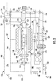
FIG. 2 is a schematic view of the generator ofFIG. 1 , showing a generator housing with an oil circuit having selectors for configuring the generator to circulate oil from a shared oil system or an independent oil system, as appropriate for a contemplated application of the generator; -
FIGS. 3A and3B are side elevation view of a separator of the generator ofFIG. 1 , showing a selector seating a flow blocker and a flow passer in seats of selector for circulating oil from a shared oil system and an independent oil system, respectively; -
FIGS. 4 and 5 are perspective views of a flow blocker and a flow passer for the generator, showing a monolithic body of the flow blocker and a flow passage of the flow passer, respectively; -
FIG. 6 is a schematic view of the generator ofFIG. 1 , showing flow blockers and flows passers disposed within the selector seats of the generator oil circuit such that the generator is operable to circulate oil from a shared oil source; -
FIG. 7 is a schematic view of the generator ofFIG. 1 , showing flow blockers and flows passers disposed within the selector seats of the generator oil circuit such that the generator is operable to circulate oil from an independent oil source; and -
FIG. 8 is a block diagram of a method of making a generator, showing steps of the method according to an embodiment. - A detailed description of one or more embodiments of the disclosed apparatus and method are presented herein by way of exemplification and not limitation with reference to the Figures.
- Reference will now be made to the drawings wherein like reference numerals identify similar structural features or aspects of the subject disclosure. For purposes of explanation and illustration, and not limitation, a partial view of an exemplary embodiment of a generator in accordance with the disclosure is shown in
FIG. 1 and is designated generally byreference character 100. Other embodiments of generators, generator arrangements, and methods of making generators in accordance with the present disclosure, or aspects thereof, are provided inFigs. 2-8 , as will be described. The generators and generator arrangements described herein can be used with shared oil systems or independent oil systems, such engine oil systems on aircraft main engines and auxiliary power units, though the present disclosure is not limited to aircraft engines or to any particular type of oil system in general. - Referring now to
FIG. 1 , afirst generator arrangement 10 and asecond generator arrangement 12 are shown. In the first generator arrangement thegenerator 100 is operatively associated with agas turbine engine 14 having anengine oil system 16. In thefirst generator arrangement 10 thegenerator 100 is arranged to circulate sharedsource oil 18 fromengine oil system 16. In thesecond generator arrangement 12 thegenerator 100 is arranged to circulateindependent source oil 20 from anindependent oil system 22, shown in dashed outline. - The
gas turbine engine 14 includes acompressor section 24, acombustor section 26, and aturbine section 28. Thegas turbine engine 14 also includes a power-take-off (PTO)shaft 30 and anaccessory gearbox 32 with anaccessory mount 34. Thecompressor section 24 is operably associated withturbine section 28 and is arranged to receive therefrom mechanical work. During operation, thecompressor section 24 ingests air from the external environment and compresses the air using the mechanical work provided by theturbine section 28. The compressed air is communicated to thecombustion section 26, which generates a flow of high pressure combustion products and communicates the high pressure combustion products to theturbine section 28. - The
turbine section 28 expands the high pressure combustion products, extracts work from the high pressure combustion products as they expand, and communicates the work to thecompressor section 24. A portion of the work extracted by theturbine section 28 is also communicated to thegenerator 100 as mechanical rotation through theaccessory gearbox 32, though thePTO shaft 30. The mechanical rotation rotates a rotor 106 (shown inFIG. 2 ) of thegenerator 100 to generate electrical power, which is used to power electrical devices connected to thegenerator 100. - As will be appreciated by those of skill in the art in view of the present disclose, heat is generated during the operation of the
generator 100. To remove this heat thegenerator 100 oil received from either theengine oil system 16 or theindependent oil system 22 is circulated through thegenerator 100. To render thegenerator 100 operable with oil from either theengine oil system 16 or theindependent oil system 22 the generator includes an oil circuit 162 (shown inFIG. 2 ) having a plurality of selectors, e.g., the oil-inselectors 174, the oil-out selector 176, and the scavenge selector 178 (shown inFIG. 2 ), the selectors arranged to configure (and re-configured, as appropriate) thegenerator 100 to circulate oil from either theengine oil system 16 or theindependent oil system 22. While shown and described herein as employing oil for coolant, those of skill in art the will appreciate that generators employing other types of fluids for cooling and/or lubrication can also benefit from the present disclosure. - With reference to
FIG. 2 , thegenerator 100 is shown. Thegenerator 100 includes ahousing 102, astator 104, and arotor 106. Thestator 104 is arranged within thehousing 102 and therotor 106 is supported for rotation relative to thestator 104. The generator also includes theoil circuit 162, which is configurable to circulate oil from either theengine oil system 16 or theindependent oil system 22, as will be described. - The
housing 102 has adrive end 114 and ananti-drive end 116. Thedrive end 114 includes a mountingfeature 118 configured and adapted to support thegenerator 100 at the accessory mount 34 (shown inFIG. 1 ) of the accessory gearbox 32 (shown inFIG. 1 ). A shared system oil-inport 120, a shared system oil-outport 122, and a shared system scavengeport 124 each extend through thehousing 102 at thedrive end 114 of thehousing 102 and are in fluid communication with an interior 126 of thehousing 102. More particularly, each of the shared system oil-inport 120, shared system oil-outport 122, and the shared system scavengeport 124 are axially overlapped by theaccessory mount 34 and are arranged to communicate shared source oil 18 (shown inFIG. 1 ) between thegenerator 100 and the engine oil system 16 (shown inFIG. 1 ). A casepressure relief valve 128 is also located on thedrive end 114 of thehousing 102 for relieving pressure from theinterior 126 of thehousing 102 when thegenerator 100 is supplied the independent source oil 20 (shown inFIG. 1 ) from the independent oil system 22 (shown inFIG. 1 ). - The
housing 102 also includes an independent system oil-inport 130, an independent system oil-outport 132, and an independent system pressure oil-fill port 134. Each of the independent system oil-inport 130, the independent system oil-outport 132, and the independent system pressure oil-fill port 134 extend through thehousing 102 at locations other than thedrive end 114 of thehousing 102, e.g., on upper and lower surfaces of the housing 102 (relative to the top ofFIG. 2 ), and are configured to communicate independent source oil 20 (shown inFIG. 1 ) between thegenerator 100 and the independent oil system 22 (shown inFIG. 1 ). - The
housing 102 additionally includes a push-to-vent feature 136, avacuum break valve 138, asight glass 140, an external visual differential pressure indicator (DPI) 142, and astandpipe port 144. The push-to-vent feature 136 is configured and adapted to selectively vent theinterior 126 of thehousing 102 to the external environment manually when thegenerator 100 is connected to the independent oil system 22 (shown inFIG. 1 ), such as upon actuation by a maintainer. Thevacuum break valve 138 is configured and adapted for equalizing pressure within theinterior 126 of thehousing 102 with the external environment manually, also when thegenerator 100 is connected to the independent oil system 22 (shown inFIG. 1 ) when actuated by a maintainer. Thesight glass 140 is configured and adapted to provide visual indication the level of oil within theinterior 124 of thehousing 102, e.g. within a sump, when thegenerator 100 is connected to theindependent oil system 22, for example to provide state of fill indication to a maintainer. The externalvisual DPI 142 provides an indication of pressure across thescavenge filter 168 when thegenerator 100 is connected to theindependent oil system 22. Thestandpipe port 144 is in fluid communication with astandpipe 146 located within theinterior 124 of the generator and is arranged discharge oil from theinterior 102 of thehousing 102 when oil level within the housing exceeds a predetermined level. - The
stator 104 includes a stator winding 148 and is fixed within theinterior 126 of thehousing 102. Therotor 106 is supported for rotation relative to the stator winding 148 by abearing arrangement 150 about arotation axis 152 and extends axially from thedrive end 114 of thehousing 102. In this respect a portion of thegenerator 100 including a shear feature and a drive feature are received within the accessory gearbox 32 (shown inFIG. 1 ) to receive mechanical rotation R from the gas turbine engine 14 (shown inFIG. 1 ) and the PTO shaft 30 (shown inFIG. 1 . It is contemplated that therotor 106 carry a magnetic element to induce current in the stator winding 148 as magnetic element rotate about therotation axis 152 relative to the stator winding 148. As shown inFIG. 2 the magnetic element is a field winding 154. - The field winding 154 is in electrical communication with an
exciter 156 through arotating rectifier 158 for generating magnetic flux during rotation with current provided by theexciter 156. More specifically, the mechanical rotation R of therotor 106 generates an excitation current using apermanent magnet generator 160 operably connected to therotor 106, which theexciter 156 communicates to therotor 106 for rectification by the rotatingrectifier 158 and application to the field winding 154. In certain embodiments thegenerator 100 can be a variable speed constant frequency (VSCF) electric machine. Examples of such VSCF electric machines includes those described inU.S. Patent Application Publication No. 2003/0164651 A1 to Tornquist et al., filed June 3, 2002 , the contents of which are incorporated herein by reference in their entirety. Although shown in described herein in the context of a wound field machine, constant speed and/or permanent magnet-type electric machines can also benefit from the present disclosure. - As will be appreciated by those of skill in the art in view of the present disclosure, structures within the interior of the
generator 100 generate heat during operation. For example, one or more electrical structure within thegenerator 100 such as the stator winding 148, thepermanent magnet generator 160, theexciter 156, the rotatingrectifier 158, and the field winding 154 can require oil to remove heat generated by resistive heating of current-carrying elements. Thebearing arrangement 150 also generates heat from friction associated with rotation of therotor 106, and can require oil for heat removal and/or lubrication. Theoil circuit 162 is arranged to circulate oil through thegenerator 100 to remove heat and/or provide lubricant, as appropriate, and is easily modified to operate with either the engine oil system 16 (shown inFIG. 1 ) or the independent oil system 22 (shown inFIG. 1 ), as suitable for a contemplated application of thegenerator 100. - The
oil circuit 162 includes thesupply conduit 108, thereturn conduit 110, and thescavenge pump 112. Theoil circuit 162 also includes asump 180, ascavenge filter 168, and aninline screen 166. In addition, theoil circuit 162 includes scavengefilter bypass conduit 164, a scavenge filter to independent system oil-outport conduit 170, and an external circuit bypass172. A plurality of selectors are arranged along theoil circuit 162,FIG. 2 showing an oil-inselector 174, an oil-out selector 176, and ascavenge selector 178. - The oil-in
selector 174 connects the independent system oil-inport 130 and the shared system oil-inport 120 to thesupply conduit 108. Thesupply conduit 108 is in turn connected to thestator 104, therotor 106, and thebearing arrangement 150. Thebearing arrangement 150 is connected to thesump 180. Therotor 106 is also connected to thesump 180 through one or more of thepermanent magnet generator 160, theexciter 156, the rotatingrectifier 158, and/or the field winding 154. - The
stator 104 is connected to the oil-out selector 176. The oil-out selector 176 is in turn connected to thescavenge pump 112 through thereturn conduit 110 and thesump 180. Thescavenge pump 112 is connected to the shared system oil-outport 122 through theinline screen 166. Thescavenge selector 178 connects thescavenge pump 112 to the shared system scavengeport 124 through the scavengefilter bypass conduit 164. Thescavenge selector 178 also connects thescavenge pump 112 to thescavenge filter 168, and therethrough to the independent system oil-outport 132. - It is contemplated that each of the plurality of selectors fluidly couple the
stator 104 to either the independent system oil-in port and or the shared system oil-in port to which the selector is connected. It is also contemplated that each of the plurality of selectors fluidly separate thestator 104 from the other of the other of the independent system port and one shared system port to which the selector is connected. In this respect the oil-inselector 174 connects thestator 104 to the independent system oil-inport 130 and the shared system oil-inport 120, the oil-out selector 176 connects thestator 104 to the shared system oil-outport 122 and the independent system oil-outport 132, and thescavenge selector 178 connects thestator 104 to the independent system oil-inport 130 and the independent system oil-outport 132. It is contemplated that the fluid communication be established by the arrangement (or re-arrangement) of flow passers, i.e.,flow passer 117,flow passer 125, and flow passer 182 (shown inFIG. 4 ,) and flow blockers, i.e.,flow blocker 121,flow blocker 129, and flow blocker 184 (shown inFIG. 4 ), in seat pairs of the respective selectors. - With reference to
FIGS. 3A and3B , the oil-inselector 174 and a portion of thesupply conduit 108 are shown. Thesupply conduit 108 is arranged within theinterior 126 of the housing 102 (shown inFIG. 2 ) and defines aflow area 190. The oil-inselector 174 includes afirst seat 186 and asecond seat 188. Thefirst seat 186 connects the independent system oil-inport 130 to the stator 104 (shown inFIG. 2 ) through thesupply conduit 108, the first seat extending through thesupply conduit 108 within ininterior 126 of thehousing 102. It is contemplated that thefirst seat 186 be defined by thehousing 102 and in this respect thefirst seat 186 extends through theflow area 190 defined bysupply conduit 108, e.g., between a firstinterior surface 194 and a secondinterior surface 196 of thesupply conduit 108 such that the oil-inselector 174 spans theflow area 190 of thesupply conduit 108. In certain embodiments thehousing 102 may include a cored or drilled body defining thesupply conduit 108, thefirst seat 186 intersecting thesupply conduit 108 within theinterior 126 of thehousing 102. On one end thefirst seat 186 is in communication with thesupply conduit 108 and on another end thefirst seat 186 is in communication with the shared system oil-inport 120. - The
second seat 188 is similar to thefirst seat 186, and additionally connects the shared system oil-inport 120 to the stator 104 (shown inFIG. 2 ) through thesupply conduit 108. It is contemplated that thesecond seat 188 connect the independent system oil-inport 130 to thestator 104 through thesupply conduit 108, thesecond seat 188 connecting to thesupply conduit 108 at a location along thesupply conduit 108 at a location between thefirst seat 186 and thestator 104. Anoptional plug 198 can be seated in within the independent system oil-inport 130 of the oil-inselector 174 on a side of theflow blocker 184 opposite thesupply conduit 108 to prevent contamination from entering the independent system oil-inport 130, simplifying re-configuration of thegenerator 100 to receive oil from an independent oil source, e.g., the independent oil system 22 (shown inFIG. 1 ). - As shown in
FIG. 3A , aflow passer 182 is fixed within thefirst seat 186 and aflow blocker 184 is fixed within thesecond seat 188. Theflow passer 182 fluidly couples the shared system oil-inport 120 to the stator 104 (shown inFIG. 2 ) and theflow blocker 184 fluidly separates the independent system oil-inport 130 to thestator 104. Fixation of theflow passer 182 within thefirst seat 186 allows the a shared oil-source, e.g., theengine oil system 16, to provide a flow of sharedsource oil 18 to thestator 104 through theflow passer 182 and thesupply conduit 108. Fixation of theflow blocker 184 within thesecond seat 188 prevents communication between the independent system oil-inport 130 and thesupply conduit 108. - It is contemplated that the
flow passer 182 and theflow blocker 184 be interchangeable with one another. In this respectFIG. 3B shows theflow passer 182 fixed within thesecond seat 188 and theflow blocker 184 fixed within thefirst seat 186. Fixation of theflow passer 182 within thesecond seat 188 allows an independent oil-source, e.g., theindependent oil system 22, to provide a flow ofindependent source oil 20 to the stator 104 (shown inFIG. 2 ) through theflow passer 182 and thesupply conduit 108. Fixation of theflow blocker 184 within thefirst seat 186 prevents communication between the shared system oil-inport 120 and thesupply conduit 108. Optionally, theplug 198 can be seated in within thefirst seat 186 on a side of theflow blocker 184 opposite thesupply conduit 108 to prevent contamination from entering the shared system oil-inport 120, simplifying re-configuration of thegenerator 100 to receive oil from a shared oil source, e.g., the engine oil system 16 (shown inFIG. 1 ). - With reference to
FIGS. 4 and 5 , theflow blocker 184 and theflow passer 182 are shown, respectively. As shown inFIG. 4 , theflow blocker 184 has amonolithic body 133 that is cylindrical in shape with afirst end 101 and a longitudinally oppositesecond end 103. A firstannular groove 105 is defined within thefirst end 101 and afirst seal member 107 is seated therein and about thefirst end 101 for compressive engagement between the interior of the first seat 186 (shown inFIG. 3A ), or the interior of thesecond seat 188, and thefirst end 101 of theflow blocker 184. A secondannular groove 109 is defined on thesecond end 103 of theflow blocker 184, asecond seal member 111 seated therein and the about thesecond end 103 also for compressive engagement between the interior of thefirst seat 186, of the interior of thesecond seat 188, and thesecond end 103 of theflow blocker 184. - A
tool engagement feature 113 is defined on thefirst end 101 of theflow blocker 184, thetool engagement feature 113 arranged to allow a tool to fix and/or remove theflow blocker 184 in thefirst seat 186 or thesecond seat 188 to configure the generator 100 (shown inFIG. 1 ) to receive oil from the engine oil system 16 (shown inFIG. 1 ) or the independent oil system 22 (shown inFIG. 1 ). As shown inFIGS. 3A and3B it is contemplated that the tool engagement feature be arranged within theinterior 126 of thehousing 102 when theflow blocker 184 is fixed within the oil-inselector 174, which prevents tampering with theoil circuit 162 of thegenerator 100 once configured for one of theengine oil system 16 and theindependent oil system 22. In certain embodiments thetool engagement feature 113 secures the flow blocker in place and/or serves as an anti-rotation feature. - With reference to
FIG. 5 , theflow passer 182 is similar to theflow blocker 184 and additionally defines aflow passage 115. Theflow passage 115 is defined longitudinally between afirst end 151 and a second end 1153 of theflow passer 182, theflow passage 115 extending laterally through theflow passer 182. As shown inFIGS. 3A and3B , it is contemplated that theflow passage 115 being in registration with thesupply conduit 108 and one of the shared system oil-in port 120 (shown inFIG. 3A ) and the independent system oil-in port 130 (shown inFIG. 3B ) once fixed within the oil-inselector 174, theflow passer 182 thereby fluidly coupling one of theengine oil system 16 and the independent oil system to thesupply conduit 108, and therethrough the stator 104 (shown inFIG. 2 ), to provide a flow of oil thereto. An o-ring 135 and an o-ring 137 seat about theflow passer 182 on longitudinally opposites sides of theflow passage 115. - With continuing reference to
FIG. 2 , the oil-out selector 176 and thescavenge selector 178 are similar to the oil-inselector 174 and are additionally connected on a side of thestator 104 opposite (relative to the direction of oil flow) the oil-inselector 174. Specifically, the oil-out selector 176 connects thestator 104 to thescavenge pump 112 through thereturn conduit 110, and to the shared system oil-outport 122 through theinline screen 166. Thescavenge selector 178 connects thescavenge pump 112 to the shared system scavengeport 124 through the scavengefilter bypass conduit 164, and to the independent system oil-inport 130 through the external circuit bypass172 and acheck valve 139 connecting the scavenge selector 718 to the independent system oil-in port. 130. As will be appreciated by those of skill in the art in view of the present disclosure, flow blocker and flow passer arrangement selection in seats of the oil-out selector 176 and thescavenge selector 178 renders thegenerator 100 operably with either a shared oil source, e.g., the engine oil system 16 (shown inFIG. 1 ), or an independent oil source, e.g., the independent oil system 22 (shown inFIG. 1 ). - With reference to
FIG. 2 , thefirst generator arrangement 10 is shown. In thefirst generator arrangement 10 thegenerator 100 is operable to circulate shared source oil received from theengine oil system 16. In this respect thegenerator 100 is supported at theaccessory mount 34 and therotor 106 coupled to the PTO shaft 30 (shown inFIG. 1 ) to receive through theaccessory gearbox 32 mechanical rotation R, thegenerator 100 thereby producing electrical power through rotation of therotor 106 relative to thestator 104. - With reference to
FIG. 6 , thefirst generator arrangement 10 is shown. In thefirst generator arrangement 10 thegenerator 100 is operable to circulate the shared source oil 18 (shown inFIG. 1 ) using theoil circuit 162. In particular theengine oil system 16 is in fluid communication with theoil circuit 162 through the shared system oil-inport 120, the shared system oil-outport 122, and the shared system scavengeport 124. Sharedsource oil 18 from theengine oil system 16 enters thegenerator 100 through the shared system oil-inport 120, flows to thestator 104 through thesupply conduit 108, and returns to the shared system oil-outport 122 through theinline screen 166. In certain embodiments a portion of the sharedsource oil 18 is also circulated by theoil circuit 162 through one or more of thebearing arrangement 150, thepermanent magnet generator 160, theexciter 156, the rotatingrectifier 158 and the field winding 154, and thereafter returned to theengine oil system 16 through thesump 180 and shared system scavengeport 124. In this respect thescavenge pump 112 draws a portion of the sharedsource oil 18 from thesump 180 and flows the sharedsource oil 18 through the scavengefilter bypass conduit 164 to the shared system scavengeport 124. Once forced through the shared system scavengeport 124 by thescavenge pump 112, the sharedsource oil 18 drawing by thescavenge pump 112 rejoins the sharedsource oil 18 returned through the shared system oil-outport 122 for recirculation by theengine oil system 16. In certain embodiments thescavenge pump 112 can have a smaller pumping capacity than that required when thegenerator 100 is configured for operation with an independent oil source, e.g., the independent oil system 22 (shown inFIG. 1 ). - Circulation of the shared
source oil 18 through thegenerator 100 by theoil circuit 162 is accomplished by disposition of flow passers and flow blockers within seats of the oil-inselector 174, the oil-out selector 176, and the scavenge selector 178of theoil circuit 162. In this respect theflow passer 182 is fixed within thefirst seat 186 of the oil-inselector 174 and theflow blocker 184 is fixed within thesecond seat 188 of the oil-inselector 174. So fixed the oil-inselector 174 fluidly couples the shared system oil-inport 120, and therethrough theengine oil system 16, to thestator 104 via thesupply conduit 108 while fluidly separating the independent system oil-inport 130 from thestator 104. - A
flow passer 117 is fixed within afirst seat 119 of the oil-out selector 176 and aflow blocker 121 is fixed within asecond seat 123 of the oil-out selector 176. So fixed the oil-out selector 176 fluidly couples thestator 104 to the shared system oil-outport 122 and fluidly separates thestator 104 from independent system oil-outport 132. - In addition, a
flow passer 125 is fixed within afirst seat 127 of thescavenge selector 178 and aflow blocker 129 is fixed within asecond seat 131 of thescavenge selector 178. So fixed thescavenge selector 178 fluidly couples thestator 104, through thesump 180 and thescavenge pump 112, to the shared system scavengeport 124. Thescavenge selector 178 also cooperates with the oil-out selector 176 to fluidly separate thestator 104, via thesump 180 and thescavenge pump 112, from the independent system oil-inport 130. It is contemplated the fixation of the flow blockers and flow passers be accomplished manually, such as when thegenerator 100 is undergoing initial assembly or during re-assembly following an overhaul. - With reference to
FIG. 7 , thesecond generator arrangement 12 is shown. In thesecond generator arrangement 12 thegenerator 100 is operable to circulate the independent source oil 20 (shown inFIG. 1 ) using theoil circuit 162. In particular, theindependent oil system 22 is in fluid communication with theoil circuit 162 through the independent system oil-inport 130 and the independent system oil-outport 132. This allows theindependent source oil 20 from theindependent oil system 22 to enter thegenerator 100 through the independent system oil-inport 130, flow to thestator 104 through thesupply conduit 108, and return to theindependent oil system 22 through the independent system oil-outport 132 through thesump 180 and scavengefilter 168. In certain embodiments a portion of theindependent source oil 20 also circulates through the one ormore bearing arrangement 150, thepermanent magnet generator 160, theexciter 156, the rotatingrectifier 158 and thefield windings 154, and thereafter returns to theindependent oil system 22 through thesump 180, scavengepump 112, and scavengefilter 168 via the independent system oil-outport 132. - Circulation of the
independent source oil 20 through thegenerator 100 by theoil circuit 162 is accomplished by changing the disposition of flow passers and flow blockers within seats of the selectors, e.g., the oil-inselector 174, the oil-out selector 176, and thescavenge selector 178, of theoil circuit 162. Specifically, the flow blocker and flow passer of each selector are switched between seats in relation to the disposition shown inFIG. 6 . For example, the respect theflow blocker 184 is fixed within thefirst seat 186 of the oil-inselector 174 and theflow passer 182 is fixed within thesecond seat 188 of the oil-inselector 174. So fixed the oil-inselector 174 fluidly couples the independent system oil-inport 130, and therethrough theindependent oil system 22, to thestator 104 through thesupply conduit 108 while the oil-inselector 174 fluidly separates the shared system oil-inport 120 from thestator 104. Further, theflow blocker 121 is fixed within afirst seat 119 of the oil-out selector 176 and aflow passer 117 is fixed within asecond seat 123 of the oil-out selector 176. So fixed the oil-out selector 176 fluidly couples thestator 104 to the independent system oil-outport 132 and fluidly separates thestator 104 from shared system oil-outport 122. In addition, theflow blocker 129 is fixed within afirst seat 127 of thescavenge selector 178 and aflow passer 125 is fixed within asecond seat 131 of thescavenge selector 178. So fixed, thescavenge selector 178 additionally fluidly couples thestator 104, through thesump 180, thescavenge filter 168 and thescavenge pump 112, to the independent system oil-outport 132 and fluidly separates thestator 104, via thesump 180 and thescavenge pump 112, from the shared system scavengeport 124. Thescavenge pump 112 in turn draws oil from thesump 180 and drives the oil out of thegenerator 100. Here again it is contemplated the fixation of the flow blockers and flow passers be accomplished manually, such as when thegenerator 100 is undergoing initial assembly or during re-assembly following an overhaul, or when thegenerator 100 is to be configured for a different oil system. - Referring now to
FIG. 8 , amethod 200 of making agenerator 100 is shown. As shown withbox 210, themethod 200 includes enclosing a stator with a stator winding within a housing, e.g., the stator 104 (shown inFIG. 2 ) with the stator winding 148 (shown inFIG. 2 ) within the housing 102 (shown inFIG. 2 ). The method also includes supporting a rotor with a rotor winding for rotation relative to the stator, e.g., the rotor 106 (shown inFIG. 2 ) with the field winding 154 (shown inFIG. 2 ), as shown withbox 220. - The stator is fluidly coupled to one of a shared system port and an independent system port by a selector, as shown with
box 230. For example, one or more of the oil-in selector 174 (shown inFIG. 2 ), the oil-out selector 176 (shown inFIG. 2 ), and the scavenge selector 178 (shown inFIG. 2 ) can fluidly couple the stator to an independent system port and fluidly separate the stator from a shared system port. Alternatively, one or more of the oil-in selector 174 (shown inFIG. 2 ), the oil-out selector 176 (shown inFIG. 2 ), and the scavenge selector 178 (shown inFIG. 2 ) can fluidly couple the stator to a shared system port and fluidly separate the stator from an independent system port. It is contemplated that the shared system port include one of the shared system oil-in port 120 (shown inFIG. 2 ), the shared system oil-out port 122 (shown inFIG. 2 ), and the shared system scavenge port 124 (shown inFIG. 2 ). It is also contemplated that the independent system port include one of the independent system oil-in port 130 (shown inFIG. 2 ) and the independent system oil-out port 132 (shown inFIG. 2 ). As shown withbox 240, the stator is fluidly separated from the other of the shared system port and the independent system port. - As shown with
boxes box 250, and the stator fluidly separated by the selector from the one of the shared system port and the independent system port, as shown withbox 260. As shown withbox 270, the connectivity provided by the selector can be changed to configure the generator for operation with a shared oil system or an independent oil system, e.g., the engine oil system 16 (shown inFIG. 1 ) or the independent oil system 22 (shown inFIG. 1 ). - The term "about" is intended to include the degree of error associated with measurement of the particular quantity based upon the equipment available at the time of filing the application. For example, "about" can include a range of ± 8% or 5%, or 2% of a given value.
- The terminology used herein is for the purpose of describing particular embodiments only and is not intended to be limiting of the present disclosure. As used herein, the singular forms "a", "an" and "the" are intended to include the plural forms as well, unless the context clearly indicates otherwise. It will be further understood that the terms "comprises" and/or "comprising," when used in this specification, specify the presence of stated features, integers, steps, operations, elements, and/or components, but do not preclude the presence or addition of one or more other features, integers, steps, operations, element components, and/or groups thereof.
- While the present disclosure has been described with reference to an exemplary embodiment or embodiments, it will be understood by those skilled in the art that various changes may be made and equivalents may be substituted for elements thereof without departing from the scope of the present disclosure. In addition, many modifications may be made to adapt a particular situation or material to the teachings of the present disclosure without departing from the essential scope thereof. Therefore, it is intended that the present disclosure not be limited to the particular embodiment disclosed as the best mode contemplated for carrying out this present disclosure, but that the present disclosure will include all embodiments falling within the scope of the claims.
Claims (15)
- A generator (100), comprising:a stator (104) with a stator winding;a rotor (106) with a field winding supported for rotation relative to the stator;a housing (102) enclosing the stator (104) and the rotor (106), the housing (102) having an independent system port connected to a shared system port by a selector; andwherein the selector fluidly couples the stator (104) and one of the independent system port and the shared system port, and wherein the selector fluidly separates the stator (104) from the other of the independent system port and the shared system port.
- The generator as recited in claim 1, wherein the housing (102) has a conduit with defining a flow area arranged within an interior of the housing (102), wherein the selector spans the flow area of the conduit; and/or
wherein the selector comprises a flow passer (182) having a tool engagement feature, wherein the tool engagement feature is located within an interior of the housing (102). - The generator as recited in claims 1 or 2, wherein the selector comprises a flow blocker (184), the flow blocker (184) comprising:a first seal member extending about a first end of the selector and compressively fixed between the housing (102) and a first seat (186) of the selector; anda second seal member extending about a second end of the selector, the second end longitudinally opposite the first end, the second seal member compressively fixed between the housing (102) and a second seat (188) of the selector.
- The generator as recited in any preceding claim, wherein the selector comprises a flow passer with a flow passage extending therethrough, the flow passage of the flow passer fluidly coupling the stator to the one of the independent system port and the shared system port; and/or wherein the selector comprises a flow blocker with a monolithic body, the monolithic body of the flow blocker fluidly separating the stator from the other of the independent system port and the shared system port.
- The generator as recited in any preceding claim, wherein the selector comprises a first seat (186) and a second seat (188), the first seat (186) connecting the independent system port to the stator, the second seat (188) connecting the shared system port to the stator.
- The generator as recited in claim 5, further comprising:a flow blocker (184) fixed within the first seat and fluidly separating the shared system port from the stator; anda flow passer (182) fixed within the second seat and fluidly coupling the independent system port to the stator; or further comprising:a flow passer (182) fixed within the first seat and fluidly coupling the shared system port to the stator; anda flow blocker (184) fixed within the second seat and fluidly separating the independent system port from the stator; and/or wherein at least one of the first seat and the second seat extend through a conduit arranged within an interior of the housing (102).
- The generator as recited in any preceding claim, wherein the housing (102) has a drive end and an anti-drive end, wherein the shared system port is arranged on the drive end of the housing, wherein the independent system port is arranged between the drive end and the anti-drive end of the housing or the anti-drive end of the housing.
- The generator as recited in any preceding claim, wherein the shared system port is a shared system oil-in port, wherein the independent system port is an independent system oil-in port, and wherein the housing has a shared system oil-out port and an independent system oil-out port connected to the selector.
- The generator as recited in claim 8, further comprising:an inline screen connecting the shared system oil-out port to the selector; anda scavenge filter connecting the independent system oil-out port to the selector; or further comprising:a scavenge pump connecting the independent system oil-out port to the selector; andan inline screen connecting the shared system oil-out port to the selector.
- The generator as recited in any preceding claim, wherein the shared system port is a shared system scavenge port, wherein the independent system port is an independent system oil-in port, the generator further comprising:a scavenge filter bypass conduit connecting the selector to the shared system scavenge port; anda check valve (139) connecting the selector to the independent system oil-in port.
- The generator as recited in any preceding claim, wherein the selector is an oil-in system selector, the generator further comprising:an oil-out selector connected to the oil-in selector by the stator (104); anda scavenge selector connected to the oil-in selector by the rotor (106).
- A generator arrangement, comprising:a generator as recited in claim 1;an independent oil system connected to the independent system port; anda plug seated in the shared system port.
- A generator arrangement, comprising:a generator as recited in claim 1;an accessory gearbox with an accessory mount supporting the generator, wherein the shared system port is arranged between the generator and the accessory mount; anda plug seated in the independent system port.
- A method of making a generator, comprising:at a housing having a shared system port and an independent system port,enclosing a stator with a stator winding in the housing;supporting a rotor with a rotor winding for rotation relative to the stator;fluidly coupling the stator with one of the shared system port and the independent system port with the selector; andfluidly separating the stator from the other of the shared system port and the independent system port with the selector.
- The method as recited in claim 14, further comprising:fluidly coupling the stator with the other of the shared system port and the independent system port with the selector; andfluidly separating the stator from the other of the of the shared system port and the independent system port with the selector.
Applications Claiming Priority (1)
| Application Number | Priority Date | Filing Date | Title |
|---|---|---|---|
| US16/355,315 US11018556B2 (en) | 2019-03-15 | 2019-03-15 | Generators operable with shared oil systems and independent oil systems |
Publications (2)
| Publication Number | Publication Date |
|---|---|
| EP3709485A1 true EP3709485A1 (en) | 2020-09-16 |
| EP3709485B1 EP3709485B1 (en) | 2024-09-25 |
Family
ID=68655310
Family Applications (1)
| Application Number | Title | Priority Date | Filing Date |
|---|---|---|---|
| EP19211118.5A Active EP3709485B1 (en) | 2019-03-15 | 2019-11-25 | Generators operable with shared oil systems and independent oil systems |
Country Status (2)
| Country | Link |
|---|---|
| US (1) | US11018556B2 (en) |
| EP (1) | EP3709485B1 (en) |
Families Citing this family (2)
| Publication number | Priority date | Publication date | Assignee | Title |
|---|---|---|---|---|
| US12173845B1 (en) * | 2023-07-21 | 2024-12-24 | General Electric Company | Bearing lubrication systems and methods for operating the same |
| US12404808B2 (en) | 2024-01-11 | 2025-09-02 | Hamilton Sundstrand Corporation | Multi temperature generator and engine shared oil |
Citations (4)
| Publication number | Priority date | Publication date | Assignee | Title |
|---|---|---|---|---|
| US20030164651A1 (en) | 2002-03-01 | 2003-09-04 | Gerald Tornquist | Generator with improved lubrication and cooling system |
| US20150244223A1 (en) * | 2014-02-21 | 2015-08-27 | Doosan Heavy Industries & Construction Co., Ltd. | Separated coolant circulation structure for water-cooled power generator and cooling method thereof |
| US20170081040A1 (en) * | 2015-09-21 | 2017-03-23 | Hamilton Sundstrand Corporation | Heat exchanger and cooling system for generator electronics cooling |
| US20180219457A1 (en) * | 2013-08-16 | 2018-08-02 | Hamilton Sundstrand Corporation | Generators with open loop active cooling |
Family Cites Families (4)
| Publication number | Priority date | Publication date | Assignee | Title |
|---|---|---|---|---|
| US5034638A (en) * | 1990-03-14 | 1991-07-23 | Westinghouse Electric Corp. | Generator auxiliary mode lubrication system and method |
| US6227221B1 (en) | 2000-10-04 | 2001-05-08 | Geoffrey W. Schmitz | Single-fluid apparatus for supplying vehicle power and lubrication fluid requirements and a system and method for fluid distribution and delivery |
| FR2911917B1 (en) | 2007-01-31 | 2013-05-17 | Hispano Suiza Sa | DISTRIBUTED GAS TURBINE GENERATOR-STARTER ARCHITECTURE |
| US10544717B2 (en) | 2016-09-07 | 2020-01-28 | Pratt & Whitney Canada Corp. | Shared oil system arrangement for an engine component and a generator |
-
2019
- 2019-03-15 US US16/355,315 patent/US11018556B2/en active Active
- 2019-11-25 EP EP19211118.5A patent/EP3709485B1/en active Active
Patent Citations (4)
| Publication number | Priority date | Publication date | Assignee | Title |
|---|---|---|---|---|
| US20030164651A1 (en) | 2002-03-01 | 2003-09-04 | Gerald Tornquist | Generator with improved lubrication and cooling system |
| US20180219457A1 (en) * | 2013-08-16 | 2018-08-02 | Hamilton Sundstrand Corporation | Generators with open loop active cooling |
| US20150244223A1 (en) * | 2014-02-21 | 2015-08-27 | Doosan Heavy Industries & Construction Co., Ltd. | Separated coolant circulation structure for water-cooled power generator and cooling method thereof |
| US20170081040A1 (en) * | 2015-09-21 | 2017-03-23 | Hamilton Sundstrand Corporation | Heat exchanger and cooling system for generator electronics cooling |
Also Published As
| Publication number | Publication date |
|---|---|
| EP3709485B1 (en) | 2024-09-25 |
| US20200295624A1 (en) | 2020-09-17 |
| US11018556B2 (en) | 2021-05-25 |
Similar Documents
| Publication | Publication Date | Title |
|---|---|---|
| RU2406846C2 (en) | Starter/generator module box integration into gear box of gas turbine | |
| US20060087123A1 (en) | Dual-rotor, single input/output starter-generator | |
| US9006942B2 (en) | Generator main stator back-iron cooling sleeve | |
| US8207644B2 (en) | Hybrid cascading lubrication and cooling system | |
| CN101389841B (en) | Integration of a starter/generator module in a gas turbine transmission housing | |
| JP5084531B2 (en) | Distributed structure for gas turbine starter / generator | |
| US3576143A (en) | Constant speed drive and generator | |
| US6750572B2 (en) | Generator with improved lubrication and cooling system | |
| EP3709485B1 (en) | Generators operable with shared oil systems and independent oil systems | |
| EP2372880A2 (en) | Low profile starter-generator | |
| EP3696952A1 (en) | Dual fluid rotating shaft | |
| EP3709487B1 (en) | Rotary electric machine and methods of cooling said rotary electric machine | |
| CN103206385A (en) | Wet Turbomachine | |
| EP4175130B1 (en) | Aircraft electric motor with integrated cooling system | |
| US9140194B2 (en) | Gas turbine engine starter-generator with integrated lube oil scavenge functionality | |
| US11058979B2 (en) | Air-oil separator | |
| GB2570656A (en) | Coolant system | |
| US11152837B2 (en) | Generator arrangements and methods of generating electric power with generator arrangements | |
| EP3425230B1 (en) | Automatically actuated disconnect couplings | |
| JP2023025334A (en) | Complex power system | |
| EP3696424B1 (en) | Dual fluid rotating shaft | |
| JP6871077B2 (en) | Motor generator device | |
| CN119522526A (en) | Motor heat exchanger | |
| US20140306564A1 (en) | Standpipe assembly |
Legal Events
| Date | Code | Title | Description |
|---|---|---|---|
| PUAI | Public reference made under article 153(3) epc to a published international application that has entered the european phase |
Free format text: ORIGINAL CODE: 0009012 |
|
| STAA | Information on the status of an ep patent application or granted ep patent |
Free format text: STATUS: THE APPLICATION HAS BEEN PUBLISHED |
|
| AK | Designated contracting states |
Kind code of ref document: A1 Designated state(s): AL AT BE BG CH CY CZ DE DK EE ES FI FR GB GR HR HU IE IS IT LI LT LU LV MC MK MT NL NO PL PT RO RS SE SI SK SM TR |
|
| AX | Request for extension of the european patent |
Extension state: BA ME |
|
| STAA | Information on the status of an ep patent application or granted ep patent |
Free format text: STATUS: REQUEST FOR EXAMINATION WAS MADE |
|
| 17P | Request for examination filed |
Effective date: 20210315 |
|
| RBV | Designated contracting states (corrected) |
Designated state(s): AL AT BE BG CH CY CZ DE DK EE ES FI FR GB GR HR HU IE IS IT LI LT LU LV MC MK MT NL NO PL PT RO RS SE SI SK SM TR |
|
| STAA | Information on the status of an ep patent application or granted ep patent |
Free format text: STATUS: EXAMINATION IS IN PROGRESS |
|
| 17Q | First examination report despatched |
Effective date: 20220202 |
|
| RIC1 | Information provided on ipc code assigned before grant |
Ipc: H02K 7/18 20060101ALI20240327BHEP Ipc: H02K 9/197 20060101ALI20240327BHEP Ipc: H02K 9/193 20060101AFI20240327BHEP |
|
| GRAP | Despatch of communication of intention to grant a patent |
Free format text: ORIGINAL CODE: EPIDOSNIGR1 |
|
| STAA | Information on the status of an ep patent application or granted ep patent |
Free format text: STATUS: GRANT OF PATENT IS INTENDED |
|
| INTG | Intention to grant announced |
Effective date: 20240506 |
|
| GRAS | Grant fee paid |
Free format text: ORIGINAL CODE: EPIDOSNIGR3 |
|
| GRAA | (expected) grant |
Free format text: ORIGINAL CODE: 0009210 |
|
| STAA | Information on the status of an ep patent application or granted ep patent |
Free format text: STATUS: THE PATENT HAS BEEN GRANTED |
|
| AK | Designated contracting states |
Kind code of ref document: B1 Designated state(s): AL AT BE BG CH CY CZ DE DK EE ES FI FR GB GR HR HU IE IS IT LI LT LU LV MC MK MT NL NO PL PT RO RS SE SI SK SM TR |
|
| REG | Reference to a national code |
Ref country code: GB Ref legal event code: FG4D |
|
| REG | Reference to a national code |
Ref country code: CH Ref legal event code: EP |
|
| REG | Reference to a national code |
Ref country code: DE Ref legal event code: R096 Ref document number: 602019059371 Country of ref document: DE |
|
| REG | Reference to a national code |
Ref country code: IE Ref legal event code: FG4D |
|
| REG | Reference to a national code |
Ref country code: LT Ref legal event code: MG9D |
|
| PG25 | Lapsed in a contracting state [announced via postgrant information from national office to epo] |
Ref country code: NO Free format text: LAPSE BECAUSE OF FAILURE TO SUBMIT A TRANSLATION OF THE DESCRIPTION OR TO PAY THE FEE WITHIN THE PRESCRIBED TIME-LIMIT Effective date: 20241225 |
|
| PG25 | Lapsed in a contracting state [announced via postgrant information from national office to epo] |
Ref country code: GR Free format text: LAPSE BECAUSE OF FAILURE TO SUBMIT A TRANSLATION OF THE DESCRIPTION OR TO PAY THE FEE WITHIN THE PRESCRIBED TIME-LIMIT Effective date: 20241226 Ref country code: FI Free format text: LAPSE BECAUSE OF FAILURE TO SUBMIT A TRANSLATION OF THE DESCRIPTION OR TO PAY THE FEE WITHIN THE PRESCRIBED TIME-LIMIT Effective date: 20240925 |
|
| PG25 | Lapsed in a contracting state [announced via postgrant information from national office to epo] |
Ref country code: BG Free format text: LAPSE BECAUSE OF FAILURE TO SUBMIT A TRANSLATION OF THE DESCRIPTION OR TO PAY THE FEE WITHIN THE PRESCRIBED TIME-LIMIT Effective date: 20240925 |
|
| PG25 | Lapsed in a contracting state [announced via postgrant information from national office to epo] |
Ref country code: LV Free format text: LAPSE BECAUSE OF FAILURE TO SUBMIT A TRANSLATION OF THE DESCRIPTION OR TO PAY THE FEE WITHIN THE PRESCRIBED TIME-LIMIT Effective date: 20240925 |
|
| PG25 | Lapsed in a contracting state [announced via postgrant information from national office to epo] |
Ref country code: RS Free format text: LAPSE BECAUSE OF FAILURE TO SUBMIT A TRANSLATION OF THE DESCRIPTION OR TO PAY THE FEE WITHIN THE PRESCRIBED TIME-LIMIT Effective date: 20241225 |
|
| REG | Reference to a national code |
Ref country code: NL Ref legal event code: MP Effective date: 20240925 |
|
| PG25 | Lapsed in a contracting state [announced via postgrant information from national office to epo] |
Ref country code: RS Free format text: LAPSE BECAUSE OF FAILURE TO SUBMIT A TRANSLATION OF THE DESCRIPTION OR TO PAY THE FEE WITHIN THE PRESCRIBED TIME-LIMIT Effective date: 20241225 Ref country code: NO Free format text: LAPSE BECAUSE OF FAILURE TO SUBMIT A TRANSLATION OF THE DESCRIPTION OR TO PAY THE FEE WITHIN THE PRESCRIBED TIME-LIMIT Effective date: 20241225 Ref country code: LV Free format text: LAPSE BECAUSE OF FAILURE TO SUBMIT A TRANSLATION OF THE DESCRIPTION OR TO PAY THE FEE WITHIN THE PRESCRIBED TIME-LIMIT Effective date: 20240925 Ref country code: GR Free format text: LAPSE BECAUSE OF FAILURE TO SUBMIT A TRANSLATION OF THE DESCRIPTION OR TO PAY THE FEE WITHIN THE PRESCRIBED TIME-LIMIT Effective date: 20241226 Ref country code: FI Free format text: LAPSE BECAUSE OF FAILURE TO SUBMIT A TRANSLATION OF THE DESCRIPTION OR TO PAY THE FEE WITHIN THE PRESCRIBED TIME-LIMIT Effective date: 20240925 Ref country code: BG Free format text: LAPSE BECAUSE OF FAILURE TO SUBMIT A TRANSLATION OF THE DESCRIPTION OR TO PAY THE FEE WITHIN THE PRESCRIBED TIME-LIMIT Effective date: 20240925 |
|
| REG | Reference to a national code |
Ref country code: AT Ref legal event code: MK05 Ref document number: 1727483 Country of ref document: AT Kind code of ref document: T Effective date: 20240925 |
|
| PG25 | Lapsed in a contracting state [announced via postgrant information from national office to epo] |
Ref country code: NL Free format text: LAPSE BECAUSE OF FAILURE TO SUBMIT A TRANSLATION OF THE DESCRIPTION OR TO PAY THE FEE WITHIN THE PRESCRIBED TIME-LIMIT Effective date: 20240925 |
|
| PG25 | Lapsed in a contracting state [announced via postgrant information from national office to epo] |
Ref country code: PT Free format text: LAPSE BECAUSE OF FAILURE TO SUBMIT A TRANSLATION OF THE DESCRIPTION OR TO PAY THE FEE WITHIN THE PRESCRIBED TIME-LIMIT Effective date: 20250127 Ref country code: IS Free format text: LAPSE BECAUSE OF FAILURE TO SUBMIT A TRANSLATION OF THE DESCRIPTION OR TO PAY THE FEE WITHIN THE PRESCRIBED TIME-LIMIT Effective date: 20250125 |
|
| PG25 | Lapsed in a contracting state [announced via postgrant information from national office to epo] |
Ref country code: SM Free format text: LAPSE BECAUSE OF FAILURE TO SUBMIT A TRANSLATION OF THE DESCRIPTION OR TO PAY THE FEE WITHIN THE PRESCRIBED TIME-LIMIT Effective date: 20240925 Ref country code: RO Free format text: LAPSE BECAUSE OF FAILURE TO SUBMIT A TRANSLATION OF THE DESCRIPTION OR TO PAY THE FEE WITHIN THE PRESCRIBED TIME-LIMIT Effective date: 20240925 |
|
| PG25 | Lapsed in a contracting state [announced via postgrant information from national office to epo] |
Ref country code: ES Free format text: LAPSE BECAUSE OF FAILURE TO SUBMIT A TRANSLATION OF THE DESCRIPTION OR TO PAY THE FEE WITHIN THE PRESCRIBED TIME-LIMIT Effective date: 20240925 |
|
| PG25 | Lapsed in a contracting state [announced via postgrant information from national office to epo] |
Ref country code: AT Free format text: LAPSE BECAUSE OF FAILURE TO SUBMIT A TRANSLATION OF THE DESCRIPTION OR TO PAY THE FEE WITHIN THE PRESCRIBED TIME-LIMIT Effective date: 20240925 Ref country code: EE Free format text: LAPSE BECAUSE OF FAILURE TO SUBMIT A TRANSLATION OF THE DESCRIPTION OR TO PAY THE FEE WITHIN THE PRESCRIBED TIME-LIMIT Effective date: 20240925 |
|
| PG25 | Lapsed in a contracting state [announced via postgrant information from national office to epo] |
Ref country code: CZ Free format text: LAPSE BECAUSE OF FAILURE TO SUBMIT A TRANSLATION OF THE DESCRIPTION OR TO PAY THE FEE WITHIN THE PRESCRIBED TIME-LIMIT Effective date: 20240925 Ref country code: PL Free format text: LAPSE BECAUSE OF FAILURE TO SUBMIT A TRANSLATION OF THE DESCRIPTION OR TO PAY THE FEE WITHIN THE PRESCRIBED TIME-LIMIT Effective date: 20240925 |
|
| PG25 | Lapsed in a contracting state [announced via postgrant information from national office to epo] |
Ref country code: IT Free format text: LAPSE BECAUSE OF FAILURE TO SUBMIT A TRANSLATION OF THE DESCRIPTION OR TO PAY THE FEE WITHIN THE PRESCRIBED TIME-LIMIT Effective date: 20240925 Ref country code: SK Free format text: LAPSE BECAUSE OF FAILURE TO SUBMIT A TRANSLATION OF THE DESCRIPTION OR TO PAY THE FEE WITHIN THE PRESCRIBED TIME-LIMIT Effective date: 20240925 |
|
| REG | Reference to a national code |
Ref country code: DE Ref legal event code: R097 Ref document number: 602019059371 Country of ref document: DE |
|
| REG | Reference to a national code |
Ref country code: CH Ref legal event code: PL |
|
| PG25 | Lapsed in a contracting state [announced via postgrant information from national office to epo] |
Ref country code: MC Free format text: LAPSE BECAUSE OF FAILURE TO SUBMIT A TRANSLATION OF THE DESCRIPTION OR TO PAY THE FEE WITHIN THE PRESCRIBED TIME-LIMIT Effective date: 20240925 |
|
| PG25 | Lapsed in a contracting state [announced via postgrant information from national office to epo] |
Ref country code: DK Free format text: LAPSE BECAUSE OF FAILURE TO SUBMIT A TRANSLATION OF THE DESCRIPTION OR TO PAY THE FEE WITHIN THE PRESCRIBED TIME-LIMIT Effective date: 20240925 |
|
| PG25 | Lapsed in a contracting state [announced via postgrant information from national office to epo] |
Ref country code: LU Free format text: LAPSE BECAUSE OF NON-PAYMENT OF DUE FEES Effective date: 20241125 |
|
| REG | Reference to a national code |
Ref country code: CH Ref legal event code: PL |
|
| PG25 | Lapsed in a contracting state [announced via postgrant information from national office to epo] |
Ref country code: CH Free format text: LAPSE BECAUSE OF NON-PAYMENT OF DUE FEES Effective date: 20241130 |
|
| PLBE | No opposition filed within time limit |
Free format text: ORIGINAL CODE: 0009261 |
|
| STAA | Information on the status of an ep patent application or granted ep patent |
Free format text: STATUS: NO OPPOSITION FILED WITHIN TIME LIMIT |
|
| REG | Reference to a national code |
Ref country code: BE Ref legal event code: MM Effective date: 20241130 |
|
| 26N | No opposition filed |
Effective date: 20250626 |
|
| PG25 | Lapsed in a contracting state [announced via postgrant information from national office to epo] |
Ref country code: SE Free format text: LAPSE BECAUSE OF FAILURE TO SUBMIT A TRANSLATION OF THE DESCRIPTION OR TO PAY THE FEE WITHIN THE PRESCRIBED TIME-LIMIT Effective date: 20240925 |
|
| PG25 | Lapsed in a contracting state [announced via postgrant information from national office to epo] |
Ref country code: BE Free format text: LAPSE BECAUSE OF NON-PAYMENT OF DUE FEES Effective date: 20241130 |
|
| PG25 | Lapsed in a contracting state [announced via postgrant information from national office to epo] |
Ref country code: IE Free format text: LAPSE BECAUSE OF NON-PAYMENT OF DUE FEES Effective date: 20241125 |
|
| PGFP | Annual fee paid to national office [announced via postgrant information from national office to epo] |
Ref country code: DE Payment date: 20251022 Year of fee payment: 7 |
|
| PGFP | Annual fee paid to national office [announced via postgrant information from national office to epo] |
Ref country code: GB Payment date: 20251023 Year of fee payment: 7 |
|
| PG25 | Lapsed in a contracting state [announced via postgrant information from national office to epo] |
Ref country code: HR Free format text: LAPSE BECAUSE OF FAILURE TO SUBMIT A TRANSLATION OF THE DESCRIPTION OR TO PAY THE FEE WITHIN THE PRESCRIBED TIME-LIMIT Effective date: 20240925 |
|
| PGFP | Annual fee paid to national office [announced via postgrant information from national office to epo] |
Ref country code: FR Payment date: 20251022 Year of fee payment: 7 |
|
| PG25 | Lapsed in a contracting state [announced via postgrant information from national office to epo] |
Ref country code: HU Free format text: LAPSE BECAUSE OF FAILURE TO SUBMIT A TRANSLATION OF THE DESCRIPTION OR TO PAY THE FEE WITHIN THE PRESCRIBED TIME-LIMIT; INVALID AB INITIO Effective date: 20191125 |
|
| PG25 | Lapsed in a contracting state [announced via postgrant information from national office to epo] |
Ref country code: CY Free format text: LAPSE BECAUSE OF FAILURE TO SUBMIT A TRANSLATION OF THE DESCRIPTION OR TO PAY THE FEE WITHIN THE PRESCRIBED TIME-LIMIT; INVALID AB INITIO Effective date: 20191125 |